DE102017008044A1 - Discharge device with Coanda stabilizer - Google Patents
Discharge device with Coanda stabilizer Download PDFInfo
- Publication number
- DE102017008044A1 DE102017008044A1 DE102017008044.5A DE102017008044A DE102017008044A1 DE 102017008044 A1 DE102017008044 A1 DE 102017008044A1 DE 102017008044 A DE102017008044 A DE 102017008044A DE 102017008044 A1 DE102017008044 A1 DE 102017008044A1
- Authority
- DE
- Germany
- Prior art keywords
- railing
- transport
- air jet
- transport device
- objects
- Prior art date
- Legal status (The legal status is an assumption and is not a legal conclusion. Google has not performed a legal analysis and makes no representation as to the accuracy of the status listed.)
- Withdrawn
Links
- 239000003381 stabilizer Substances 0.000 title 1
- 238000007599 discharging Methods 0.000 claims abstract description 6
- 238000000034 method Methods 0.000 claims description 13
- 238000011144 upstream manufacturing Methods 0.000 claims description 5
- 239000003570 air Substances 0.000 description 77
- 230000000694 effects Effects 0.000 description 19
- 230000008569 process Effects 0.000 description 9
- 230000000087 stabilizing effect Effects 0.000 description 7
- 230000008901 benefit Effects 0.000 description 4
- 238000004806 packaging method and process Methods 0.000 description 3
- 230000007704 transition Effects 0.000 description 3
- 230000001133 acceleration Effects 0.000 description 2
- 230000002950 deficient Effects 0.000 description 2
- BUHVIAUBTBOHAG-FOYDDCNASA-N (2r,3r,4s,5r)-2-[6-[[2-(3,5-dimethoxyphenyl)-2-(2-methylphenyl)ethyl]amino]purin-9-yl]-5-(hydroxymethyl)oxolane-3,4-diol Chemical compound COC1=CC(OC)=CC(C(CNC=2C=3N=CN(C=3N=CN=2)[C@H]2[C@@H]([C@H](O)[C@@H](CO)O2)O)C=2C(=CC=CC=2)C)=C1 BUHVIAUBTBOHAG-FOYDDCNASA-N 0.000 description 1
- 230000002411 adverse Effects 0.000 description 1
- 239000012080 ambient air Substances 0.000 description 1
- 235000013361 beverage Nutrition 0.000 description 1
- 230000008859 change Effects 0.000 description 1
- 238000012217 deletion Methods 0.000 description 1
- 230000037430 deletion Effects 0.000 description 1
- 239000007789 gas Substances 0.000 description 1
- 239000011521 glass Substances 0.000 description 1
- 230000005484 gravity Effects 0.000 description 1
- 239000011261 inert gas Substances 0.000 description 1
- 238000007689 inspection Methods 0.000 description 1
- 230000003993 interaction Effects 0.000 description 1
- 239000000463 material Substances 0.000 description 1
- 230000007246 mechanism Effects 0.000 description 1
Images


Classifications
-
- B—PERFORMING OPERATIONS; TRANSPORTING
- B65—CONVEYING; PACKING; STORING; HANDLING THIN OR FILAMENTARY MATERIAL
- B65G—TRANSPORT OR STORAGE DEVICES, e.g. CONVEYORS FOR LOADING OR TIPPING, SHOP CONVEYOR SYSTEMS OR PNEUMATIC TUBE CONVEYORS
- B65G47/00—Article or material-handling devices associated with conveyors; Methods employing such devices
- B65G47/52—Devices for transferring articles or materials between conveyors i.e. discharging or feeding devices
- B65G47/525—Devices for transferring articles or materials between conveyors i.e. discharging or feeding devices using fluid jets
-
- B—PERFORMING OPERATIONS; TRANSPORTING
- B65—CONVEYING; PACKING; STORING; HANDLING THIN OR FILAMENTARY MATERIAL
- B65G—TRANSPORT OR STORAGE DEVICES, e.g. CONVEYORS FOR LOADING OR TIPPING, SHOP CONVEYOR SYSTEMS OR PNEUMATIC TUBE CONVEYORS
- B65G21/00—Supporting or protective framework or housings for endless load-carriers or traction elements of belt or chain conveyors
- B65G21/20—Means incorporated in, or attached to, framework or housings for guiding load-carriers, traction elements or loads supported on moving surfaces
- B65G21/2045—Mechanical means for guiding or retaining the load on the load-carrying surface
- B65G21/2063—Mechanical means for guiding or retaining the load on the load-carrying surface comprising elements not movable in the direction of load-transport
- B65G21/2072—Laterial guidance means
-
- B—PERFORMING OPERATIONS; TRANSPORTING
- B65—CONVEYING; PACKING; STORING; HANDLING THIN OR FILAMENTARY MATERIAL
- B65G—TRANSPORT OR STORAGE DEVICES, e.g. CONVEYORS FOR LOADING OR TIPPING, SHOP CONVEYOR SYSTEMS OR PNEUMATIC TUBE CONVEYORS
- B65G47/00—Article or material-handling devices associated with conveyors; Methods employing such devices
- B65G47/74—Feeding, transfer, or discharging devices of particular kinds or types
- B65G47/76—Fixed or adjustable ploughs or transverse scrapers
- B65G47/766—Adjustable ploughs or transverse scrapers
-
- B—PERFORMING OPERATIONS; TRANSPORTING
- B65—CONVEYING; PACKING; STORING; HANDLING THIN OR FILAMENTARY MATERIAL
- B65G—TRANSPORT OR STORAGE DEVICES, e.g. CONVEYORS FOR LOADING OR TIPPING, SHOP CONVEYOR SYSTEMS OR PNEUMATIC TUBE CONVEYORS
- B65G47/00—Article or material-handling devices associated with conveyors; Methods employing such devices
- B65G47/74—Feeding, transfer, or discharging devices of particular kinds or types
- B65G47/82—Rotary or reciprocating members for direct action on articles or materials, e.g. pushers, rakes, shovels
-
- B—PERFORMING OPERATIONS; TRANSPORTING
- B65—CONVEYING; PACKING; STORING; HANDLING THIN OR FILAMENTARY MATERIAL
- B65G—TRANSPORT OR STORAGE DEVICES, e.g. CONVEYORS FOR LOADING OR TIPPING, SHOP CONVEYOR SYSTEMS OR PNEUMATIC TUBE CONVEYORS
- B65G2201/00—Indexing codes relating to handling devices, e.g. conveyors, characterised by the type of product or load being conveyed or handled
- B65G2201/02—Articles
- B65G2201/0235—Containers
- B65G2201/0244—Bottles
-
- B—PERFORMING OPERATIONS; TRANSPORTING
- B65—CONVEYING; PACKING; STORING; HANDLING THIN OR FILAMENTARY MATERIAL
- B65G—TRANSPORT OR STORAGE DEVICES, e.g. CONVEYORS FOR LOADING OR TIPPING, SHOP CONVEYOR SYSTEMS OR PNEUMATIC TUBE CONVEYORS
- B65G2207/00—Indexing codes relating to constructional details, configuration and additional features of a handling device, e.g. Conveyors
- B65G2207/06—Air cushion support of articles
Landscapes
- Engineering & Computer Science (AREA)
- Mechanical Engineering (AREA)
- Branching, Merging, And Special Transfer Between Conveyors (AREA)
- Discharge Of Articles From Conveyors (AREA)
- Intermediate Stations On Conveyors (AREA)
Abstract
Die Vorrichtung zum Ausleiten von Objekten (18) wie Behältern, Gebinden, Packstücken, die auf einer Transportvorrichtung (10) befördert werden, umfasst eine erste Transporteinrichtung (12), auf der die Objekte (18) einreihig transportiert werden, eine zweite Transporteinrichtung (16), die seitlich der ersten Transporteinrichtung (12) angeordnet ist, und eine Ausleiteinrichtung (14), die an einer Seite der Transportvorrichtung vorgesehen ist und mit der ein auszuleitendes Objekt (18) von der ersten Transporteinrichtung (12) auf die zweite Transporteinrichtung (16) ausgeleitet wird. Die Vorrichtung umfasst außerdem ein Geländer (20), das an einer der Ausleiteinrichtung gegenüber liegenden Seite der Transportvorrichtung vorgesehen ist, und eine Einrichtung zur Erzeugung eines Luftstrahls (24), wobei die Einrichtung zur Erzeugung des Luftstrahls so konfiguriert ist, dass der erzeugte Luftstrahl (24) parallel zum Geländer (20) verläuft.
Description
Die vorliegende Anmeldung betrifft eine Vorrichtung zum Ausleiten von Objekten wie Behältern, Gebinden, Packstücken, die auf einer Transportvorrichtung befördert werden.The present application relates to a device for discharging objects such as containers, containers, packages, which are transported on a transport device.
Solche Ausleitvorrichtungen werden z.B. zum Aussortieren von fehlerbehafteten Getränkeflaschen oder anderen leeren oder bereits gefüllten Lebensmittelbehältern oder Verpackungen eingesetzt. Die Transporteinrichtungen sind dabei Transportbänder, Gliederkettenförderer oder dergleichen, wobei zwei oder mehr solcher Transporteure zumindest abschnittsweise parallel nebeneinander laufen und die Ausleitvorrichtung die fehlerbehafteten Flaschen oder Behälter von einem ersten Transporteur auf einen der benachbarten Transporteure verschieben soll.Such diversion devices are e.g. Used for sorting out defective beverage bottles or other empty or already filled food containers or packaging. The transport devices are conveyor belts, link chain conveyors or the like, wherein two or more such conveyors run parallel to each other at least in sections and the diversion device is to move the faulty bottles or containers from a first conveyor to one of the adjacent conveyors.
Aus der
Aus der
Aus der
Aus der
Insbesondere wenn die auszuleitenden Objekte relativ leicht sind, kann es bei den aus dem Stand der Technik bekannten Ausleitvorrichtungen vorkommen, dass die Objekte während der Ausleitung umkippen.In particular, if the objects to be diverted are relatively light, it may occur in the case of the diversion devices known from the prior art that the objects tip over during the discharge.
Aufgabe der vorliegenden Erfindung ist es daher, das Ausleitverfahren weiter zu verbessern und die Gefahr eines Umkippens der auszuleitenden Objekte weiter zu verringern.It is therefore an object of the present invention to further improve the diversion method and to further reduce the risk of the objects to be tipped over.
Gelöst wird diese Aufgabe bei der Vorrichtung der eingangs genannten Art durch die Merkmale von Anspruch 1. Die Vorrichtung zum Ausleiten von Objekten, die auf einer Transportvorrichtung befördert werden, umfasst eine erste Transporteinrichtung, auf der die Objekte einreihig transportiert werden, eine zweite Transporteinrichtung, die neben der ersten Transporteinrichtung angeordnet ist, und eine Ausleiteinrichtung, die auszuleitende Objekte von der ersten Transporteinrichtung auf die zweite Transporteinrichtung verschiebt. Die Ausleiteinrichtung ist an einer Seite der Transportvorrichtung vorgesehen. Auf der der Ausleiteinrichtung gegenüberliegenden Seite der Transportvorrichtung ist ein Geländer vorgesehen zur Führung der auszuleitenden Objekte. Die Ausleiteinrichtung umfasst weiterhin eine Einrichtung zur Erzeugung eines Luftstrahls mit mindestens einer Strömungskomponente, die parallel zum Geländer verläuft.This object is achieved in the device of the type mentioned by the features of claim 1. The device for discharging objects that are transported on a transport device comprises a first transport device on which the objects are transported in a single row, a second transport device, the is arranged next to the first transport means, and a diverting device which moves objects to be diverted from the first transport means to the second transport means. The diversion device is provided on one side of the transport device. On the opposite side of the discharge device of the transport device, a railing is provided for guiding the objects to be guided. The diversion device furthermore comprises a device for generating an air jet with at least one flow component which runs parallel to the railing.
In der vorliegenden Erfindung wird generell von einem „Luftstrahl“ gesprochen. Natürlich kann der Strahl auch mit einem anderen gasförmigen Medium erstellt werden. Zum Beispiel können inerte Gase oder Schutzgase verwendet werden, wenn die zu transportierenden Objekte dies erfordern. Der Begriff „Luftstrahl“ soll also nicht als limitiert auf „Luft“ als gasförmiges Medium verstanden werden.In the present invention is generally spoken of an "air jet". Of course, the beam can also be created with another gaseous medium. For example, inert gases or shielding gases may be used if the objects to be transported require it. The term "air jet" should therefore not be understood as limited to "air" as a gaseous medium.
Objekte im Sinne der vorliegenden Erfindung können dabei Behälter wie Glasflaschen, Plastikflaschen, Container, Dosen, Gebinde oder andere Packstücke sein. Die vorliegende Erfindung eignet sich besonders zum Ausleiten von leichten Behältern wie leeren Kunststoffbehältern oder leeren Dosen, die aufgrund ihres geringen Gewichts beim Transport sehr leicht umkippen können.Objects within the meaning of the present invention may be containers such as glass bottles, plastic bottles, containers, cans, containers or other packages. The present invention is particularly suitable for the discharge of lightweight containers such as empty plastic containers or empty cans, which can easily tip over due to their low weight during transport.
Bei der vorliegenden Erfindung ist auf der der Ausleiteinrichtung gegenüber liegenden Seite entlang der ersten und zweiten Transporteinrichtung ein Geländer zur Führung der auszuleitenden Objekte vorgesehen. Dieses Geländer erstreckt sich dabei zunächst parallel entlang der ersten Transporteinrichtung. Im Bereich der Ausleiteinrichtung ist das Geländer kurvenförmig ausgeführt und folgt dem Transportweg der auszuleitenden Flaschen. Am Ende der Ausleitvorrichtung verläuft das Geländer dann seitlich der zweiten Transporteinrichtung. Das Geländer dient dabei der Führung und Stabilisierung der ausgeleiteten Flaschen.In the present invention, a railing for guiding the objects to be guided out is provided on the side opposite the discharge device along the first and second transport means. This railing extends while initially parallel along the first transport device. In the area of the diversion device, the railing is curved and follows the transport path of the bottles to be diverted. At the end of the diversion device, the railing then extends laterally of the second transport device. The railing serves to guide and stabilize the discharged bottles.
Erfindungsgemäß ist weiterhin eine Einrichtung zur Erzeugung eines Luftstrahls, der parallel zum Geländer verläuft, vorgesehen. Dieser Luftstrahl stellt eine vorzugsweise lokal begrenzte Luftströmung dar, die entlang der durch das Geländer definierten Ebene verläuft.According to the invention, a device for generating an air jet, which runs parallel to the railing, is furthermore provided. This air jet represents a preferably localized air flow which runs along the plane defined by the railing.
Die Luftströmung bildet einerseits ein Luftpolster und dient dazu, harte Kollisionen der auszuleitenden Objekte mit dem Geländer abzufedern. Zum anderen übt die Luftströmung eine in Richtung des Geländers anziehende Kraft auf die auszuleitenden Objekte aus. Diese anziehende Kraft wird durch den Coanda-Effekt hervorgerufen. Der Coanda-Effekt tritt auf, wenn örtlich begrenzte Luftströmungen an Oberflächen vorbeigeführt werden.The air flow on the one hand forms an air cushion and serves to cushion hard collisions of the objects to be diverted with the railing. On the other hand, the air flow exerts a tightening in the direction of the railing force on the auszuleitenden objects. This attractive power is caused by the Coanda effect. The Coanda effect occurs when localized airflows are routed past surfaces.
Die auszuleitenden Objekte werden aufgrund des Coanda-Effekts also einerseits an das Geländer gedrückt, und andererseits sorgt der Luftstrom dafür, dass die Objekte keine harten Kollisionen mit dem Geländer erleiden. Insgesamt werden die Objekte daher nach dem Ausleitvorgang sicher am Führungsgeländer der zweiten Transporteinrichtung entlang geführt.Due to the Coanda effect, the objects to be diverted are therefore pressed against the railing on the one hand, and on the other hand the air flow ensures that the objects do not suffer any hard collisions with the railing. Overall, therefore, the objects are safely guided along the guide railing of the second transport device after the diversion process.
Da die durch den Coanda-Effekt hervorgerufene anziehende Kraft auf die auszuleitenden Objekte relativ klein ist, eignet sich die vorliegende Erfindung insbesondere zur Stabilisierung von relativ leichten Objekten wie leeren Flaschen oder Dosen.Since the attractive force caused by the Coanda effect on the objects to be diverted is relatively small, the present invention is particularly suitable for stabilizing relatively light objects such as empty bottles or cans.
Der Coanda-Effekt tritt bei lokal begrenzten Strömungen auf, die sich entlang einer Oberfläche erstrecken. Aus diesem Grund ist es vorteilhaft, wenn die Einrichtung zur Erzeugung der Luftströmung mindestens eine Düse aufweist. Mit dieser Düse kann der Strahl gezielt in der gewünschten Orientierung am Geländer der zweiten Transportvorrichtung entlang geführt werden.The Coanda effect occurs in localized flows that extend along a surface. For this reason, it is advantageous if the device for generating the air flow has at least one nozzle. With this nozzle, the beam can be guided in the desired orientation along the railing of the second transport device targeted.
Zur Erzeugung des Coanda-Effekts ist es notwendig, dass der Luftstrahl parallel zum Geländer verläuft. In einer Ausführungsform kann der Luftstrahl dabei parallel zum Geländer und in Transportrichtung entlang des Geländers verlaufen. Da in dieser Konfiguration der Luftstrahl dem Verlauf des Geländers folgt, ist in dieser Ausführungsform die Länge des wirksamen Bereichs relativ groß. Zu berücksichtigen ist allerdings, dass die auszuleitenden Objekte aufgrund des von hinten kommenden Luftstrahls zusätzlich beschleunigt werden können. Dies muss bei der Dimensionierung der Ausleiteinrichtung unter Umständen berücksichtigt werden. Dieser Effekt kann dabei auch vorteilhaft ausgenutzt werden, um ein Abbremsen der auszuleitenden Flaschen durch die Ausleiteinrichtung zu kompensieren.To create the Coanda effect, it is necessary that the air jet is parallel to the railing. In one embodiment, the air jet can thereby run parallel to the railing and in the transport direction along the railing. In this configuration, since the air jet follows the course of the railing, in this embodiment, the length of the effective area is relatively large. However, it must be taken into account that the objects to be diverted can be additionally accelerated due to the air jet coming from behind. This may have to be taken into account when dimensioning the diversion device. This effect can also be advantageously exploited to compensate for a deceleration of the auszuleitenden bottles by the diversion.
Ein solcher Luftstrahl kann vorteilhaft durch Verwendung eines Geländers mit Hohlprofil erreicht werden. Zum Beispiel kann das Geländer die Form eines C-Profils haben, wobei auf der dem Transportbereich zugewandten Seite des Geländers eine durchgängige Öffnung oder Schlitz vorgesehen ist. Der Auslass der Einrichtung zur Erzeugung des Luftstrahls kann dabei im Inneren des Hohlprofils des Geländers angeordnet sein. Durch die Öffnung kann der Luftstrahl dann im Wesentlichen parallel zum Geländer und in Transportrichtung dem Verlauf des Geländers folgend austreten.Such an air jet can be advantageously achieved by using a railing with a hollow profile. For example, the railing may have the shape of a C-profile with a continuous opening or slot provided on the side of the railing facing the transport area. The outlet of the device for generating the air jet can be arranged inside the hollow profile of the railing. Through the opening of the air jet can then emerge substantially parallel to the railing and in the direction of transport following the course of the railing.
Diese Ausführungsform hat darüber hinaus den Vorteil, dass die Luftströmung nie vollends durch die auszuleitenden Objekte abgeschirmt werden kann. Unabhängig von der jeweiligen Ausleitaufgabe, kann bei dieser Ausführungsform eine vorbestimmte Länge des Einflussbereichs des Luftstrahls vorgesehen werden.This embodiment also has the advantage that the air flow can never be completely shielded by the objects to be diverted. Regardless of the respective diverting task, in this embodiment, a predetermined length of the influence of the air jet can be provided.
Durch die Positionierung der Düse kann bestimmt werden ab welcher Position entlang der Ausleitvorrichtung der Luftstrahl erzeugt wird und ab wann der Coanda-Effekt auftritt. Die stabilisierende Wirkung des Coanda-Effekts kann dadurch zum Beispiel auch bereits in Transportrichtung vor der Ausleiteinrichtung ausgenutzt werden.By positioning the nozzle, it can be determined from which position along the diverting device the air jet is generated and from when the Coanda effect occurs. The stabilizing effect of the Coanda effect can thereby be exploited, for example, already in the transport direction before the diversion device.
Das Geländer kann grundsätzlich einen beliebigen geeigneten Querschnitt aufweisen. Insbesondere die Innenseite des Geländers, also die Seite an der die Objekte und der Luftstrahl entlang geführt werden, kann gerade, gekrümmt, konvex oder konkav ausgeführt sein.The railing may in principle have any suitable cross-section. In particular, the inside of the railing, so the side on which the objects and the air jet are guided along, can be straight, curved, convex or concave.
Der Luftstrahl muss nicht notwendigerweise parallel zur Transportrichtung verlaufen. Der Coanda-Effekt wirkt sich auch aus, wenn der Luftstrahl zwar parallel zum Geländer, aber zum Beispiel von oben oder von unten unter einem Winkel am Geländer vorbeigeführt wird. Ganz allgemein kann der Luftstrahl unter einem beliebigen Winkel in der Geländerebene am Geländer vorbeigeführt werden.The air jet does not necessarily have to run parallel to the transport direction. The Coanda effect also has an effect if the air jet is moved parallel to the railing, but for example from above or from below at an angle to the railing. In general, the air jet can be guided past the railing at any angle in the terrain level.
Je größer der Winkel des Luftstrahls gegenüber der Transportebene ist, desto kürzer ist der Geländerbereich, der von dem Luftstrahl erfasst wird und in dem der Coanda-Effekt auf die auszuleitenden Objekte wirkt. Gleichzeitig verringert sich dabei aber auch die aufgrund des Luftstrahls bewirkte direkte Beschleunigung der Flaschen. Der Winkel unter dem der Luftstrahl in der Geländerebene an dem Geländer vorbeigeführt wird, kann je nach Ausleitaufgabe und je nach Anwendungsgebiet individuell optimal eingestellt werden.The greater the angle of the air jet with respect to the transport plane, the shorter is the railing area, which is detected by the air jet and in which the Coanda effect acts on the objects to be diverted. At the same time, however, the direct acceleration of the bottles caused by the air jet is also reduced. The angle under which the air jet in the terrain level at the Railing is passed, can be optimally adjusted individually depending on the diversion task and depending on the application.
Die Strömungsgeschwindigkeit, der Luftdruck, das Strahlprofil usw. können ebenfalls in Abhängigkeit der jeweiligen Ausleitaufgabe und je nach Anwendungsgebiet individuell eingestellt werden. Zur Generierung des Luftstrahls können handelsübliche Kompressoren oder Verdichter eingesetzt werden. Die Spezifikationen der eingesetzten Kompressoren können dabei an die jeweilige Ausleitaufgabe angepasst werden. Es hat sich gezeigt, dass für die Ausleitung von herkömmlichen leeren PET Behältern, Verdichter mit einer Nennleistung von zwischen 1 und 4 kW, vorzugsweise von etwa 1,5 kW, und einem Durchfluss von zwischen 40 und 100 m3/h, vorzugsweise etwa 65 m3/h, bei einem MaximalDruck von zwischen 200 und 600 mbar ausreichend sind. Um die Durchflussmenge zu begrenzen kann zum Beispiel zusätzlich ein Frequenzumrichter eingesetzt werden, so dass der Verdichter nicht ausschließlich bei der üblichen Netzfrequenz von 50 Hz, sondern auch bei beliebigen kleineren Frequenzen betrieben werden kann.The flow rate, the air pressure, the beam profile, etc. can also be set individually depending on the respective diversion task and depending on the application. Commercially available compressors or compressors can be used to generate the air jet. The specifications of the compressors used can be adapted to the respective diverting task. It has been found that for the discharge of conventional empty PET containers, compressors having a nominal power of between 1 and 4 kW, preferably of about 1.5 kW, and a flow of between 40 and 100 m 3 / h, preferably about 65 m 3 / h, are sufficient at a maximum pressure of between 200 and 600 mbar. In order to limit the flow rate, for example, a frequency converter can be used in addition, so that the compressor can be operated not only at the usual mains frequency of 50 Hz, but also at any lower frequencies.
Der Begriff „Transporteinrichtungen“ wie er hierin verwendet wird, umfasst jegliche Art von typischerweise beim Transport von den oben angegebenen Objekten verwendeten Transporteuren. Flaschen oder Dosen werden vorzugsweise auf Gliederkettenförderern oder Transportbändern transportiert, die über Umlenkrollen motorisch angetrieben werden und sowohl geradlinig als auch kurvengängig ausgeführt sein können. Die vorliegende Erfindung ist aber nicht auf die Verwendung bei Gliederkettenförderern oder Bändern beschränkt.As used herein, the term "transport means" includes any type of conveyors typically used in the transportation of the objects specified above. Bottles or cans are preferably transported on link chain conveyors or conveyor belts, which are motor-driven via deflection rollers and can be designed both straight and curved. However, the present invention is not limited to use with link chain conveyors or belts.
Die Transporteinrichtungen können jeweils geradlinig ausgeführt sein und entweder parallel oder unter einem bestimmten Winkel zueinander angeordnet sein. Geradlinige Transportvorrichtungen sind einfacher in der Handhabung und unterliegen einem geringeren Verschleiß.The transport devices may each be rectilinear and be arranged either parallel or at a certain angle to each other. Straight line transport devices are easier to handle and subject to less wear.
Der Winkel zwischen der ersten und der zweiten Transportvorrichtung ist dabei prinzipiell beliebig wählbar. Vorzugsweise beträgt der Winkel zwischen der ersten und zweiten Transporteinrichtung zwischen 0° und 90°, weiter vorzugsweise zwischen 30° und 60° und besonders bevorzugt etwa 45°. Die Wahl des Winkels hängt unter anderem auch von der Geschwindigkeit ab, mit der die Objekte auf der ersten Transporteinrichtung gefördert werden. Bei sehr niedrigen Geschwindigkeiten der ersten Transporteinrichtung kann der Winkel, unter dem die zweite Transporteinrichtung angeordnet ist, sehr groß, z.B. über 80° werden. Bei sehr hohen Geschwindigkeiten muss der Winkel dagegen kleiner gewählt werden.The angle between the first and the second transport device is basically arbitrary. Preferably, the angle between the first and second transport means is between 0 ° and 90 °, more preferably between 30 ° and 60 °, and most preferably about 45 °. The choice of angle depends, among other things, on the speed with which the objects are conveyed on the first transport device. At very low speeds of the first conveyor, the angle at which the second conveyor is located may be very large, e.g. over 80 °. At very high speeds, however, the angle must be chosen smaller.
Grundsätzlich ist es auch möglich, dass der Winkel zwischen der ersten und zweiten Transporteinrichtung einstellbar ist. Hierzu kann zum Beispiel die zweite Transporteinrichtung beweglich ausgeführt sein und über einen Stellmechanismus angesteuert werden. Wenn der Winkel zwischen den Transporteinrichtungen einstellbar ist, kann die Ausleitvorrichtung flexibel an unterschiedliche zu transportierende Objekte angepasst werden.In principle, it is also possible that the angle between the first and second transport means is adjustable. For this purpose, for example, the second transport means can be designed to be movable and controlled by an adjusting mechanism. If the angle between the transport devices is adjustable, the diversion device can be flexibly adapted to different objects to be transported.
Bei bestimmten Ausführungsformen der Erfindung können die erste und die zweite Transporteinrichtung im Bereich der Ausleiteinrichtung übereinander angeordnet sein. Dies ist insbesondere bei geradlinig verlaufenden zweiten Transporteinrichtungen sinnvoll. Durch diese gestapelte Anordnung kann eine durchgängige Transportfläche gewährleistet werden, ohne dass unbewegte Übergangselemente zwischen den Transporteinrichtungen nötig sind. Solche Übergangselemente würden zu unerwünschten Reibungseffekten führen und könnten die Ausleitung negativ beeinflussen.In certain embodiments of the invention, the first and the second transport means may be arranged one above the other in the region of the diversion device. This makes sense, especially in the case of rectilinear second transport devices. By this stacked arrangement, a continuous transport surface can be ensured without immobile transition elements between the transport devices are necessary. Such transition elements would lead to undesirable frictional effects and could adversely affect the discharge.
Die Transportfläche der ersten bzw. oberen Transporteinrichtung kann dabei relativ dünnwandig ausgeführt sein und etwa nur 0,2 mm betragen, so dass nur eine geringe Stufe von den auszuleitenden Objekten bei dem Übergang von der ersten auf die zweite Transporteinrichtung bewältigt werden muss. Dies ist üblicherweise möglich, ohne dass die Objekte dabei umkippen.The transport surface of the first or upper transport device can be designed to be relatively thin-walled and be only about 0.2 mm, so that only a small step of the objects to be guided must be handled in the transition from the first to the second transport device. This is usually possible without the objects falling over.
Vorzugsweise kann die oberhalb angeordnete Transporteinrichtung in Transportrichtung asymmetrisch ausgeführt sein, so dass die Transportfläche der ersten Transporteinrichtung in Richtung der zweiten Transporteinrichtung verlängert ist, und somit eine größere Überlappungsfläche zwischen den beiden Transporteinrichtungen gegeben ist.Preferably, the transport device arranged above can be asymmetrical in the transport direction, so that the transport surface of the first transport device is extended in the direction of the second transport device, and thus a larger overlap area is provided between the two transport devices.
Die zweite Transporteinrichtung kann auch einen nicht-geradlinigen oder kurvenförmigen Verlauf haben. Vorzugsweise verläuft die zweite Transporteinrichtung in Förderrichtung stromaufwärts der Ausleiteinrichtung im Wesentlichen parallel zur ersten Transporteinrichtung, nimmt dann im Bereich der Ausleitvorrichtung einen kurvenförmigen Verlauf, und geht dann wiederum in einen geradlinigen Bereich über, der dann den Winkel zwischen den beiden Transporteinrichtungen definiert. Auch eine nicht-geradlinig angeordnete zweite Transporteinrichtung kann unterhalb der ersten Transporteinrichtung angeordnet sein. Grundsätzlich kann auch oder nur die erste Transporteinrichtung einen nicht-geradlinigen Verlauf haben.The second transport device may also have a non-straight or curved course. The second transport device preferably runs in the conveying direction upstream of the diversion device substantially parallel to the first transport device, then takes a curved course in the region of the diversion device, and then in turn merges into a rectilinear region which then defines the angle between the two transport devices. A non-rectilinear second transport device may also be arranged below the first transport device. In principle, even or only the first transport device may have a non-straight course.
Wenn die zweite Transporteinrichtung einen kurvenförmigen oder konvexen Verlauf aufweist, ist auch das Führungsgeländer im Bereich der zweiten Transporteinrichtung entsprechend konvex geformt. Der Effekt der vorliegenden Erfindung kann dadurch aber trotzdem erzielt werden. Aufgrund des Coanda-Effekts folgt nämlich der Luftstrahl dem Geländerverlauf. Dieses Verhalten des Luftstrahls ist insbesondere dann vorteilhaft, wenn der Luftstrahl im Wesentlichen in Transportrichtung parallel zum Geländer geführt wird, da dann auch bei kurvenförmigem Verlauf der zweiten Transportrichtung der Luftstrahl dem Verlauf des Führungsgeländers folgt. Aber auch wenn der Luftstrahl unter einem Winkel gegenüber der Transportebene ausgerichtet ist, kann dieser Effekt ausgenutzt werden. Bei solchen Ausführungsformen kann der Strahl zum Beispiel von oben kommend an einer konvex geformten Innenseite des Geländers vorbeigeführt werden, um dann an der Unterseite des Geländers mit einer nach außen gerichteten Strömungskomponente die Ausleitvorrichtung zu verlassen, ohne dass es zu störenden Verwirbelungen kommt, die die Stabilität der auszuleitenden Objekte beinträchtigen könnte.If the second transport device has a curved or convex course, the guide railing in the region of the second transport device is correspondingly convexly shaped. Nevertheless, the effect of the present invention can be achieved thereby. Because of the Coanda effect, namely, the air jet follows the railing course. This behavior of the air jet is particularly advantageous if the air jet is guided substantially parallel to the railing in the transport direction, since then follows the course of the guide railing even with a curved course of the second transport direction of the air jet. But even if the air jet is aligned at an angle to the transport plane, this effect can be exploited. In such embodiments, for example, the jet may be passed past a convexly-shaped inside of the railing from above to then exit the discharge device at the bottom of the railing with an outwardly directed flow component, without causing troublesome swirls that cause stability could affect the objects to be diverted.
Das Ausleitelement kann grundsätzlich ein beliebiges, dem Fachmann bekanntes Ausleitelement sein. Bevorzugterweise kann das Ausleitelement ein steuerbarer Pusher oder Schieber sein, der zum Beispiel über einen positionsgesteuerten Linearmotor angetrieben wird. Solche Linearmotoren eignen sich besonders, da sie mit hoher Geschwindigkeit und hoher Präzision angesteuert werden und hohe Stellkräfte erzeugen können.In principle, the diversion element can be any diversion element known to the person skilled in the art. Preferably, the diverting element may be a controllable pusher or slider which is driven, for example, by a position-controlled linear motor. Such linear motors are particularly suitable because they are driven at high speed and high precision and can generate high actuating forces.
Wenn ein Pusher als Ausleiteinrichtung verwendet wird, dann wird dieser bevorzugt so eingestellt, dass die Objekte geführt ausgeleitet werden, dass also der Pusher und das auszuleitende Objekt über eine möglichst lange Zeit in direktem Kontakt zueinander sind. Je länger ein Objekt geführt wird, desto geringer ist die Wahrscheinlichkeit, dass das Objekt während des Ausleitens kippt. Am Ende des Ausleitvorgangs, also wenn das auszuleitende Objekt sich gerade auf der zweiten Transporteinrichtung befindet, bewegt sich dieses dann idealerweise bereits in Richtung und mit der Geschwindigkeit der zweiten Transporteinrichtung, so dass es in dieser Phase zu keiner Relativbewegung zwischen der Transporteinrichtung und dem Objekt kommt. Dadurch wird die Verkippsicherheit der Ausleitvorrichtung wesentlich erhöht.If a pusher is used as a diverting device, then this is preferably set so that the objects are routed out guided, so that the pusher and the object to be guided are in direct contact with each other for as long as possible. The longer an object is guided, the lower the likelihood that the object tilts during the deletion. At the end of the diverting process, ie when the object to be diverted is currently located on the second transport device, this then ideally already moves in the direction and at the speed of the second transport device, so that there is no relative movement between the transport device and the object in this phase , As a result, the tilting security of the diversion device is substantially increased.
Ein Pusher kann senkrecht oder in beliebigem Winkel relativ zur ersten Transporteinrichtung angeordnet sein. Vorzugsweise ist die Stellkraft des Pushers so groß, dass auszuleitende Objekte unabhängig von ihrem Gewicht und der Reibung auf den Transporteinrichtungen immer mit derselben Geschwindigkeitskomponente senkrecht zur Transportrichtung der ersten Transporteinrichtung beaufschlagt werden.A pusher can be arranged perpendicular or at any angle relative to the first transport device. Preferably, the actuating force of the pusher is so great that objects to be diverted are always subjected to the same speed component perpendicular to the transport direction of the first transport device, regardless of their weight and the friction on the transport devices.
Die Ausleiteinrichtung kann auch eine Reihe von Ausleitsegmenten umfassen, wobei die einzelnen Ausleitsegmente einzeln oder gemeinsam ansteuerbar sind und zusammen eine kontinuierliche Ablenkfläche bilden. Der Vorteil einer solchen Ausleitvorrichtung ist, dass die Richtung der Ausleitung durch die Ablenkfläche fest vorgegeben ist, und somit unabhängig von der Transportgeschwindigkeit der ersten Transporteinrichtung ist. Darüber hinaus werden die Objekte zu jedem Zeitpunkt an einem Geländer geführt, so dass dies wiederum zur Erhöhung der Stabilität des Ausleitprozesses beiträgt.The diversion device can also comprise a series of diversion segments, wherein the individual diversion segments can be actuated individually or jointly and together form a continuous deflection surface. The advantage of such a diversion device is that the direction of the discharge is predetermined by the deflection surface, and thus is independent of the transport speed of the first transport device. In addition, the objects are guided at any time on a railing, so that in turn contributes to increasing the stability of the diversion process.
Ausleitvorrichtungen, die aus einzelnen Ausleitsegmenten bestehen sind im Stand der Technik hinlänglich bekannt und stellvertretend wird an dieser Stelle auf die Ausführungen in der
Bevorzugter Weise ist die Ausleiteinrichtung auf der einen Seite der Transporteinrichtung angebracht. Die zweite Transporteinrichtung, auf die die auszuleitenden Objekte verschoben werden, ist dann auf der gegenüberliegenden Seite der ersten Transporteinrichtung angebracht. Das Führungsgeländer, an dem sich der Luftstrahl erstreckt ist, auf der der Ausleiteinrichtung gegenüberliegenden Seite der jeweiligen Transporteinrichtung. Das Führungsgeländer erstreckt sich dabei zunächst parallel entlang der ersten Transporteinrichtung und folgt dann dem kurvenförmigen Verlauf des Transportwegs der auszuleitenden Flaschen. Am Ende der Ausleitvorrichtung verläuft das Geländer dann seitlich der zweiten Transporteinrichtung.Preferably, the diversion device is mounted on one side of the transport device. The second transport means, to which the objects to be conveyed are displaced, is then mounted on the opposite side of the first transport means. The guide railing, on which the air jet extends, on the side of the respective transport device opposite the diversion device. The guide railing extends initially parallel along the first transport device and then follows the curved course of the transport path of the auszuleitenden bottles. At the end of the diversion device, the railing then extends laterally of the second transport device.
Bei Transporteinrichtungen, die mit sehr hohen Geschwindigkeiten von über 80.000 Flaschen pro Stunde betrieben werden, kann es ausreichend sein, dass nur ein Teil der Ausleitsegmente verwendet wird, um eine Rampe zu bilden, die den auszuleitenden Objekten den benötigten Querimpuls vermitteln. Die Objekte bewegen sich dann aufgrund ihrer Massenträgheit ungeführt von der ersten Transporteinrichtung herunter und gelangen dann mit der gewünschten Geschwindigkeit und Bewegungsrichtung auf die zweite Transporteinrichtung. Der kurze ungeführte Bewegungsabschnitt beeinträchtigt in diesem Fall den Ausleitvorgang kaum.For conveyors operating at very high speeds of over 80,000 bottles per hour, it may be sufficient to use only a portion of the diverting segments to form a ramp which will give the objects to be diverted the required cross-pulse. The objects then move down due to their inertia unguided from the first transport device and then arrive at the desired speed and direction of movement on the second transport device. The short unguided movement section in this case hardly affects the diversion process.
Um den Ausleitvorgang zu optimieren, können über stromaufwärts der Ausleitvorrichtung installierte Inspektionseinrichtungen zusätzliche Daten zu den auszuleitenden Objekten bestimmt werden. Auf diese Weise können zum Beispiel Parameter wie Gewicht, Geschwindigkeit, Material, Reibung oder Inhalt eines auszuleitenden Objekts bestimmt werden. Diese Informationen sind zwar grundsätzlich nicht notwendig, können aber verwendet werden, um den Ausleitvorgang noch gezielter zu steuern.In order to optimize the diversion process, inspection devices installed upstream of the diversion device can be used to determine additional data on the objects to be diverted. In this way, for example, parameters such as weight, speed, material, friction or content of an object to be derived can be determined. Although this information is not necessary in principle, it can be used to control the diversion process in a more targeted manner.
Die vorliegende Erfindung betrifft auch ein Verfahren zum Ausleiten von Objekten, wobei die Objekte auf einer ersten Transporteinrichtung einreihig transportiert werden, wobei die auszuzuleitenden Objekte von einer Ausleiteinrichtung von der ersten Transporteinrichtung auf eine zweite Transporteinrichtung ausgeleitet werden. Auf der der Ausleiteinrichtung gegenüberliegenden Seite ist ein Geländer vorgesehen zur Führung der auszuleitenden Objekte. Mittels einer Einrichtung zur Erzeugung eines Luftstrahls wird ein Luftstrahls erzeugt, der parallel zu diesem Geländer verläuft. The present invention also relates to a method for discharging objects, wherein the objects are transported in a single row on a first transport device, wherein the objects to be diverted are led away from a diverting device from the first transport device to a second transport device. On the side opposite the diversion device, a railing is provided for guiding the objects to be guided out. By means of a device for generating an air jet, an air jet is generated, which runs parallel to this railing.
Ein weiterer Vorteil der vorliegenden Erfindung liegt darin, dass Vorrichtungen, bei denen ausgeleitete Objekte zudem noch unter einer geänderten Richtung weiter gefördert werden, mit Hilfe der vorliegenden Erfindung kompakter gebaut werden können. Bei herkömmlichen Transportsystemen musste hierfür bisher ein zweistufiges Verfahren eingesetzt werden. Zunächst werden die auszuleitenden Objekte auf eine parallel-laufende Bahn ausgeleitet. Anschließend können diese ausgeleiteten Objekte über einen Kurventransporteur oder dergleichen auf die gewünschte Transportrichtung gebracht werden. Aufgrund dieses sequentiellen Verfahrens tritt bei derartigen herkömmlichen Systemen ein relativ hoher Platzbedarf auf. Die vorliegende Erfindung erlaubt es dagegen, auf kürzerem Transportweg sowohl eine Ausleitung als auch eine Richtungsänderung der auszuleitenden Objekte herbeizuführen.A further advantage of the present invention is that devices in which discharged objects are further conveyed even under a changed direction can be made more compact by means of the present invention. In conventional transport systems, a two-stage process had previously been used for this purpose. First, the objects to be diverted to a parallel-running path are routed. Subsequently, these discharged objects can be brought to the desired transport direction via a cam carrier or the like. Due to this sequential method, such conventional systems require a relatively large amount of space. By contrast, the present invention makes it possible to bring about a diversion as well as a change of direction of the objects to be diverted on a shorter transport path.
Ausführungsbeispiele der Erfindung werden nachfolgend anhand der Zeichnung erläutert. Es zeigen:
-
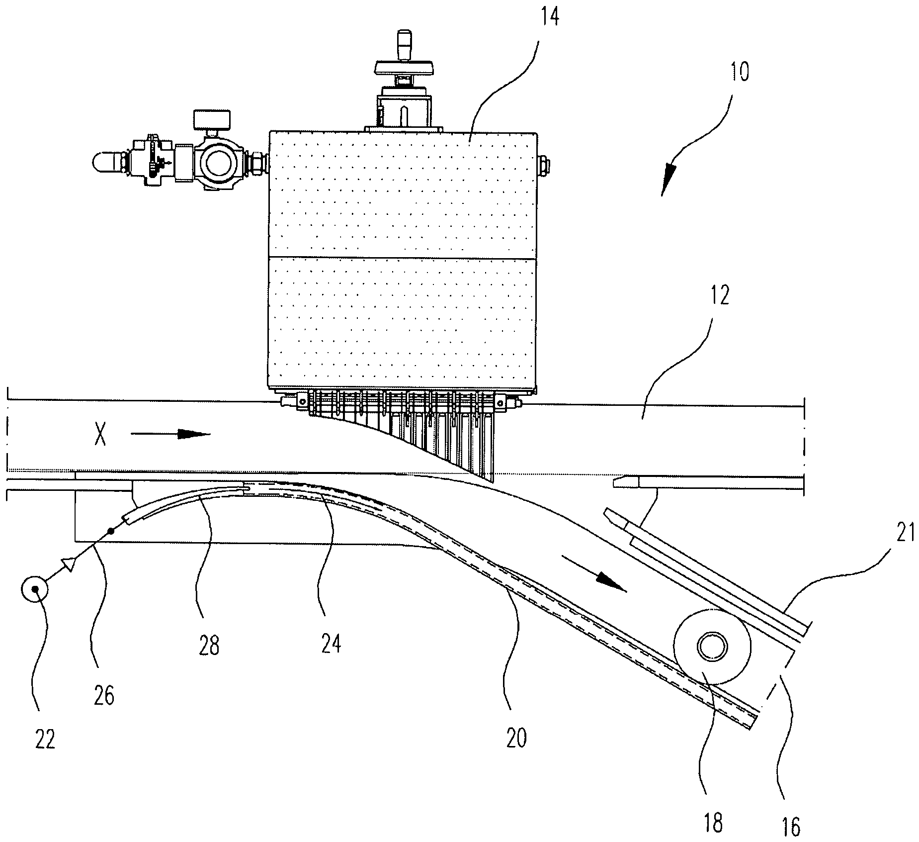
1 Aufsicht einer Ausleitvorrichtung mit einer geradlinigen ersten Transporteinrichtung und einer kurvenförmigen zweiten Transporteinrichtung; -
2 Querschnitt der zweiten Transporteinrichtung im Ausleitungsbereich; -
3 Querschnitte verschiedener Geländerprofile; -
4 Aufsicht einer weiteren Ausleitvorrichtung, wobei sich der Luftstrahl unter einem Winkel gegenüber der Transportebene erstreckt; -
5 Seitenansicht der Ausleitvorrichtung mit Geländer und schräg verlaufendem Luftstrahl gemäß4 , -
6 Querschnitt der zweiten Transporteinrichtung gemäß4 im Ausleitungsbereich, -
7 Aufsicht einer Ausleitvorrichtung mit einer geradlinigen ersten Transporteinrichtung und einer parallel dazu verlaufenden zweiten Transporteinrichtung, und8 Ausleitvorrichtung gemäß7 mit Pusher als Ausleiteinrichtung;
-
1 Top view of a diverting device with a rectilinear first conveyor and a curved second conveyor; -
2 Cross section of the second transport device in the discharge area; -
3 Cross sections of various railing profiles; -
4 Top view of another discharge device, wherein the air jet extends at an angle relative to the transport plane; -
5 Side view of the diversion device with railing and oblique air jet according to4 . -
6 Cross section of the second transport device according to4 in the diversion area, -
7 Top view of a diverting device with a rectilinear first transport device and a parallel thereto extending second transport device, and8th Guidance device according to7 with pusher as diversion device;
Die Ausleiteinrichtung
Gegenüber der Ausleiteinrichtung ist ein abschnittsweise kurvenförmiges Geländer
Die Ausleitweiche
Aufgrund des Coanda-Effekts folgt der Luftstrahl
Der Luftstrahl wirkt dabei stabilisierend auf die ausgeleiteten Flaschen
Die Düse
In der in
Zur Erzeugung des Luftstrahls
In
Zur Erzeugung des Luftstrahls kann ein handelsüblicher Verdichter verwendet werden. Zum Beispiel kann dies ein Verdichter mit einer Leistung von 1,5 kW mit einer Blasluftmenge von 70 m3/h bei 400 mbar sein.To generate the air jet, a commercial compressor can be used. For example, this may be a compressor with a power of 1.5 kW with a blown air quantity of 70 m 3 / h at 400 mbar.
Das Geländer
In den in
Eine solche Ausführungsform ist in den
Der stabilisierende Luftstrahl
Das Geländerprofil ist in diesem Fall, wie in
Da in dieser Ausführungsform die in Transportrichtung verlaufende Komponente des Luftstrahls
Bei der Realisierung der erfindungsgemäßen Ausleitvorrichtung können die Winkel α, β und die Geschwindigkeit des Luftstrahls
In
Die in
BezugszeichenlisteLIST OF REFERENCE NUMBERS
- 1010
- AusleitweicheAusleitweiche
- 1212
- erste Transporteinrichtungfirst transport device
- 1414
- Ausleiteinrichtungdiversion
- 14a14a
- Ausleitsegmentediversion
- 1616
- zweite Transporteinrichtungsecond transport device
- 1818
- Flaschenbottles
- 2020
- Geländerrailing
- 20a20a
- GeländerinnenseiteTerrain channel side
- 2121
- Geländerrailing
- 2222
- DruckluftgeneratorCompressed air generator
- 2424
- Luftstrahlair jet
- 2626
- DruckluftschlauchCompressed air hose
- 2828
- Düsejet
- 3030
- Geländeröffnungrailings opening
ZITATE ENTHALTEN IN DER BESCHREIBUNG QUOTES INCLUDE IN THE DESCRIPTION
Diese Liste der vom Anmelder aufgeführten Dokumente wurde automatisiert erzeugt und ist ausschließlich zur besseren Information des Lesers aufgenommen. Die Liste ist nicht Bestandteil der deutschen Patent- bzw. Gebrauchsmusteranmeldung. Das DPMA übernimmt keinerlei Haftung für etwaige Fehler oder Auslassungen.This list of the documents listed by the applicant has been generated automatically and is included solely for the better information of the reader. The list is not part of the German patent or utility model application. The DPMA assumes no liability for any errors or omissions.
Zitierte PatentliteraturCited patent literature
- WO 0068120 [0003]WO 0068120 [0003]
- EP 1175361 B1 [0003]EP 1175361 B1 [0003]
- DE 102009003847 A1 [0004]DE 102009003847 A1 [0004]
- DE 3623327 C2 [0005]DE 3623327 C2 [0005]
- EP 0019117 A1 [0006, 0039]EP 0019117 A1 [0006, 0039]
Claims (9)
Priority Applications (13)
| Application Number | Priority Date | Filing Date | Title |
|---|---|---|---|
| DE102017008044.5A DE102017008044A1 (en) | 2017-08-25 | 2017-08-25 | Discharge device with Coanda stabilizer |
| RU2020111450A RU2731801C1 (en) | 2017-08-25 | 2018-08-16 | Discharge device with stabilizing device creating a coanda effect |
| CA3068155A CA3068155C (en) | 2017-08-25 | 2018-08-16 | Diverting apparatus with coanda stabilizing device |
| PCT/EP2018/072233 WO2019038177A1 (en) | 2017-08-25 | 2018-08-16 | EXTERNAL DEVICE WITH COANDA STABILIZATION DEVICE |
| CN201880052482.1A CN111032539B (en) | 2017-08-25 | 2018-08-16 | Device and method for exporting objects transported on a transport device |
| JP2020511357A JP6915153B2 (en) | 2017-08-25 | 2018-08-16 | Divider with Coanda stabilizer |
| BR112020000869-9A BR112020000869B1 (en) | 2017-08-25 | 2018-08-16 | APPARATUS AND METHOD FOR DEVELOPING OBJECTS |
| EP18759588.9A EP3672893B1 (en) | 2017-08-25 | 2018-08-16 | Diverting apparatus with coanda stabilizing device |
| DK18759588.9T DK3672893T3 (en) | 2017-08-25 | 2018-08-16 | Discharge device with coanda stabilizer |
| MX2020002101A MX2020002101A (en) | 2017-08-25 | 2018-08-16 | Diverting apparatus with coanda stabilizing device. |
| ES18759588T ES2897882T3 (en) | 2017-08-25 | 2018-08-16 | Diverter apparatus with Coanda effect stabilizing device |
| US16/637,963 US10745211B2 (en) | 2017-08-25 | 2018-08-16 | Diverting apparatus with Coanda stabilizing device |
| KR1020207005370A KR102298764B1 (en) | 2017-08-25 | 2018-08-16 | Path switching device with Coanda stabilization device |
Applications Claiming Priority (1)
| Application Number | Priority Date | Filing Date | Title |
|---|---|---|---|
| DE102017008044.5A DE102017008044A1 (en) | 2017-08-25 | 2017-08-25 | Discharge device with Coanda stabilizer |
Publications (1)
| Publication Number | Publication Date |
|---|---|
| DE102017008044A1 true DE102017008044A1 (en) | 2019-02-28 |
Family
ID=63371674
Family Applications (1)
| Application Number | Title | Priority Date | Filing Date |
|---|---|---|---|
| DE102017008044.5A Withdrawn DE102017008044A1 (en) | 2017-08-25 | 2017-08-25 | Discharge device with Coanda stabilizer |
Country Status (12)
| Country | Link |
|---|---|
| US (1) | US10745211B2 (en) |
| EP (1) | EP3672893B1 (en) |
| JP (1) | JP6915153B2 (en) |
| KR (1) | KR102298764B1 (en) |
| CN (1) | CN111032539B (en) |
| CA (1) | CA3068155C (en) |
| DE (1) | DE102017008044A1 (en) |
| DK (1) | DK3672893T3 (en) |
| ES (1) | ES2897882T3 (en) |
| MX (1) | MX2020002101A (en) |
| RU (1) | RU2731801C1 (en) |
| WO (1) | WO2019038177A1 (en) |
Cited By (1)
| Publication number | Priority date | Publication date | Assignee | Title |
|---|---|---|---|---|
| DE102024119274A1 (en) * | 2024-07-08 | 2026-01-08 | Krones Aktiengesellschaft | Device and method for transporting unit loads with a transport switch |
Families Citing this family (4)
| Publication number | Priority date | Publication date | Assignee | Title |
|---|---|---|---|---|
| FR3120615B1 (en) * | 2021-03-10 | 2024-09-06 | Etablissements Andre Zalkin Et Cie | Automated shutter dispensing device |
| DE102021125919A1 (en) * | 2021-10-06 | 2023-04-06 | Krones Aktiengesellschaft | Device and method for diverting piece goods with diverting segments operated by linear motors |
| US12515892B2 (en) * | 2022-08-17 | 2026-01-06 | Innovation Associates, Inc. | Pneumatic conveyance jet diverter |
| EP4332030A1 (en) | 2022-08-30 | 2024-03-06 | Rychiger AG | Device for transporting mouldings |
Citations (4)
| Publication number | Priority date | Publication date | Assignee | Title |
|---|---|---|---|---|
| EP0019117A1 (en) | 1979-04-27 | 1980-11-26 | Bernhard Heuft | Apparatus for laterally deflecting piece goods from a first path of travel to a second path of travel |
| DE3623327C2 (en) | 1986-07-11 | 1991-07-25 | Centro Kontrollsysteme Gmbh, 5900 Siegen, De | |
| WO2000068120A1 (en) | 1999-05-05 | 2000-11-16 | Heuft Systemtechnik Gmbh | Device for singling out articles from a flow of such articles |
| DE102009003847A1 (en) | 2009-04-29 | 2010-11-04 | Krones Ag | Apparatus and method for discharging objects from a moving conveyor |
Family Cites Families (25)
| Publication number | Priority date | Publication date | Assignee | Title |
|---|---|---|---|---|
| US3465870A (en) * | 1967-10-11 | 1969-09-09 | Ermanco Inc | Diverter for conveyor systems |
| US3552537A (en) * | 1968-07-22 | 1971-01-05 | Barry Wehmiller Co | Container flow control conveyer system |
| US3848746A (en) * | 1969-08-08 | 1974-11-19 | Stork Amsterdam | Apparatus for diverting a row of cylindrical bodies alternately into two paths of travel |
| JPS5185489U (en) * | 1974-12-27 | 1976-07-08 | ||
| DE2801387A1 (en) * | 1978-01-13 | 1979-07-19 | Bernhard Heuft | SORTING MACHINE |
| DE3228453C2 (en) * | 1982-07-30 | 1990-06-21 | Krones Ag Hermann Kronseder Maschinenfabrik, 8402 Neutraubling | Device for widening and slowing down a stream of upright bottles or the like. |
| JPS617161A (en) * | 1984-06-19 | 1986-01-13 | Chugai Ro Kogyo Kaisha Ltd | Floating/supporting device for stripe member |
| DE3916335A1 (en) * | 1989-05-19 | 1990-11-22 | Niederberger Kg Heinrich | Deflector for goods along conveyor track - has main and branch lines and incorporates pivot axle, guide arm and inner track section |
| US5135101A (en) * | 1991-10-02 | 1992-08-04 | Peco Controls Corporation | Diverter of articles on conveyor |
| JPH07157082A (en) * | 1993-12-10 | 1995-06-20 | Kirin Eng Kk | Plastic bottle conveying conveyor |
| US5388682A (en) * | 1994-02-23 | 1995-02-14 | Peco Controls Corporation | Diverter for diverting articles transported along a conveyor belt |
| DE4409660A1 (en) * | 1994-03-21 | 1994-08-18 | Voith Gmbh J M | Tail cutting and feeding device |
| EP0720958B1 (en) * | 1994-07-23 | 1999-04-21 | Yoshitaka Aoyama | Part feed control device for vibration type part feeder |
| US5611647A (en) * | 1994-08-17 | 1997-03-18 | Ouellette Machinery Systems, Inc. | Diverter for bottle air conveyor |
| DE29716459U1 (en) * | 1997-09-12 | 1999-01-21 | Heuft Systemtechnik Gmbh | Device for discharging objects that are transported on a conveyor |
| US6401904B1 (en) * | 1999-01-11 | 2002-06-11 | Materials Handling Systems, Inc. | Method and apparatus for separating objects |
| US6145650A (en) * | 1999-01-29 | 2000-11-14 | Graham Packaging Company L.P. | Apparatus and method for transferring blow-molded containers to a trimmer |
| NL1018391C2 (en) * | 2001-06-26 | 2003-01-07 | Machf Houdijk B V | Device for discharging products from a transport system. |
| US7331443B2 (en) * | 2004-04-22 | 2008-02-19 | Amcor Limited | Vertical parallel transportation of caps |
| FR2911587B1 (en) * | 2007-01-22 | 2009-04-17 | Sidel Participations | DEVICE FOR CONVEYING OBJECTS, ESPECIALLY PREFORMED, BOTTLES OR THE LIKE, BY BLOWING AIR |
| US9309060B2 (en) * | 2011-06-08 | 2016-04-12 | Illinois Tool Works Inc. | Conveying and alignment nozzle |
| DE102013107565A1 (en) * | 2013-07-16 | 2015-01-22 | Khs Gmbh | Method and transport device for converting a first container stream into a second container stream |
| DE102014203118B4 (en) * | 2014-02-20 | 2019-07-18 | Dürkopp Fördertechnik GmbH | Switchable switch for influencing a flow of individual goods in a conveyor system, conveyor system with such a switchable switch and method for switching such a switchable switch |
| JP6484482B2 (en) * | 2014-06-30 | 2019-03-13 | AvanStrate株式会社 | Glass plate manufacturing method and glass plate manufacturing apparatus |
| CN206345399U (en) * | 2016-12-30 | 2017-07-21 | 上海紫泉饮料工业有限公司 | The chain of falling bottle bottle separating device |
-
2017
- 2017-08-25 DE DE102017008044.5A patent/DE102017008044A1/en not_active Withdrawn
-
2018
- 2018-08-16 CA CA3068155A patent/CA3068155C/en active Active
- 2018-08-16 DK DK18759588.9T patent/DK3672893T3/en active
- 2018-08-16 RU RU2020111450A patent/RU2731801C1/en active
- 2018-08-16 JP JP2020511357A patent/JP6915153B2/en active Active
- 2018-08-16 KR KR1020207005370A patent/KR102298764B1/en active Active
- 2018-08-16 CN CN201880052482.1A patent/CN111032539B/en active Active
- 2018-08-16 MX MX2020002101A patent/MX2020002101A/en unknown
- 2018-08-16 EP EP18759588.9A patent/EP3672893B1/en active Active
- 2018-08-16 ES ES18759588T patent/ES2897882T3/en active Active
- 2018-08-16 WO PCT/EP2018/072233 patent/WO2019038177A1/en not_active Ceased
- 2018-08-16 US US16/637,963 patent/US10745211B2/en active Active
Patent Citations (5)
| Publication number | Priority date | Publication date | Assignee | Title |
|---|---|---|---|---|
| EP0019117A1 (en) | 1979-04-27 | 1980-11-26 | Bernhard Heuft | Apparatus for laterally deflecting piece goods from a first path of travel to a second path of travel |
| DE3623327C2 (en) | 1986-07-11 | 1991-07-25 | Centro Kontrollsysteme Gmbh, 5900 Siegen, De | |
| WO2000068120A1 (en) | 1999-05-05 | 2000-11-16 | Heuft Systemtechnik Gmbh | Device for singling out articles from a flow of such articles |
| EP1175361B1 (en) | 1999-05-05 | 2003-03-26 | Heuft Systemtechnik Gmbh | Device for singling out articles from a flow of such articles |
| DE102009003847A1 (en) | 2009-04-29 | 2010-11-04 | Krones Ag | Apparatus and method for discharging objects from a moving conveyor |
Cited By (1)
| Publication number | Priority date | Publication date | Assignee | Title |
|---|---|---|---|---|
| DE102024119274A1 (en) * | 2024-07-08 | 2026-01-08 | Krones Aktiengesellschaft | Device and method for transporting unit loads with a transport switch |
Also Published As
| Publication number | Publication date |
|---|---|
| CN111032539A (en) | 2020-04-17 |
| ES2897882T3 (en) | 2022-03-03 |
| WO2019038177A1 (en) | 2019-02-28 |
| KR20200034772A (en) | 2020-03-31 |
| EP3672893A1 (en) | 2020-07-01 |
| JP2020531384A (en) | 2020-11-05 |
| US10745211B2 (en) | 2020-08-18 |
| JP6915153B2 (en) | 2021-08-04 |
| BR112020000869A2 (en) | 2020-07-21 |
| RU2731801C1 (en) | 2020-09-08 |
| CN111032539B (en) | 2021-08-24 |
| MX2020002101A (en) | 2020-07-20 |
| CA3068155C (en) | 2022-05-03 |
| EP3672893B1 (en) | 2021-10-06 |
| DK3672893T3 (en) | 2021-11-01 |
| US20200207552A1 (en) | 2020-07-02 |
| KR102298764B1 (en) | 2021-09-06 |
| CA3068155A1 (en) | 2019-02-28 |
Similar Documents
| Publication | Publication Date | Title |
|---|---|---|
| EP3672893B1 (en) | Diverting apparatus with coanda stabilizing device | |
| EP3248914B1 (en) | Chute for piece goods and method for using such a chute | |
| EP0286080B1 (en) | Device for controlling the transfer of objects | |
| EP0029614A1 (en) | Device for the lateral deviation of articles from a first conveying device to a second one | |
| DE102011014495A1 (en) | Device and method for grouping piece goods | |
| DE3202991A1 (en) | DEVICE FOR NARROWING AND ACCELERATING A CURRENT OF URGENT BOTTLES OR THE LIKE. | |
| EP2298651A2 (en) | Method and device for grouping items | |
| EP2287079A2 (en) | Device for grouping and/or separating articles | |
| EP1012087B1 (en) | Device for outward guidance of articles transported on a conveyer | |
| DE2530886C3 (en) | Device for arranging isolated objects that are randomly oriented in opposite directions | |
| DE60116314T2 (en) | Method and device for the orderly discharge of disorderly supplied products | |
| DE4342084C2 (en) | Device for aligning objects | |
| DE60202002T2 (en) | METHOD AND DEVICE FOR WRAPPING PRINTED PRODUCTS | |
| EP0121106B1 (en) | Device for distributing objects on two or several delivering conveyors | |
| DE102019207724A1 (en) | MOVING STACKS OF TRAY WITH A DENESTER UNIT | |
| EP1215142A1 (en) | Rail-guided conveyor device and conveyor system | |
| DE2645464C2 (en) | Device for the direct conveyance of light objects in a channel | |
| DE19700512B4 (en) | Sorting and feeding machine | |
| DE102004023181B4 (en) | Feeding machine | |
| EP4452792A1 (en) | Apparatus and method for conveying and apportioning | |
| DE3926966C2 (en) | ||
| DE10051790A1 (en) | Cigarette filling system and equipment feeds mass cigarette flow over filling sector whose containers fill with cigarettes at acute angle as container base lowers to maximum fill level | |
| EP1655246B1 (en) | Device and procedure for dividing a product stream by means of a chute | |
| EP3822201A1 (en) | Conveyor device and method for sorting piece goods | |
| EP4419456B1 (en) | Deflecting device for an elongate item |
Legal Events
| Date | Code | Title | Description |
|---|---|---|---|
| R163 | Identified publications notified | ||
| R119 | Application deemed withdrawn, or ip right lapsed, due to non-payment of renewal fee |