DE102016214173A1 - tachograph - Google Patents
tachograph Download PDFInfo
- Publication number
- DE102016214173A1 DE102016214173A1 DE102016214173.2A DE102016214173A DE102016214173A1 DE 102016214173 A1 DE102016214173 A1 DE 102016214173A1 DE 102016214173 A DE102016214173 A DE 102016214173A DE 102016214173 A1 DE102016214173 A1 DE 102016214173A1
- Authority
- DE
- Germany
- Prior art keywords
- paper box
- box unit
- locking
- receiving shaft
- operating position
- Prior art date
- Legal status (The legal status is an assumption and is not a legal conclusion. Google has not performed a legal analysis and makes no representation as to the accuracy of the status listed.)
- Ceased
Links
- 238000003780 insertion Methods 0.000 claims abstract description 31
- 230000037431 insertion Effects 0.000 claims abstract description 31
- 230000001846 repelling effect Effects 0.000 claims description 5
- 230000002093 peripheral effect Effects 0.000 claims description 4
- FGRBYDKOBBBPOI-UHFFFAOYSA-N 10,10-dioxo-2-[4-(N-phenylanilino)phenyl]thioxanthen-9-one Chemical compound O=C1c2ccccc2S(=O)(=O)c2ccc(cc12)-c1ccc(cc1)N(c1ccccc1)c1ccccc1 FGRBYDKOBBBPOI-UHFFFAOYSA-N 0.000 description 1
- 208000027418 Wounds and injury Diseases 0.000 description 1
- 230000006378 damage Effects 0.000 description 1
- 208000014674 injury Diseases 0.000 description 1
- 230000035939 shock Effects 0.000 description 1
Images


Classifications
-
- G—PHYSICS
- G07—CHECKING-DEVICES
- G07C—TIME OR ATTENDANCE REGISTERS; REGISTERING OR INDICATING THE WORKING OF MACHINES; GENERATING RANDOM NUMBERS; VOTING OR LOTTERY APPARATUS; ARRANGEMENTS, SYSTEMS OR APPARATUS FOR CHECKING NOT PROVIDED FOR ELSEWHERE
- G07C5/00—Registering or indicating the working of vehicles
- G07C5/08—Registering or indicating performance data other than driving, working, idle, or waiting time, with or without registering driving, working, idle or waiting time
- G07C5/12—Registering or indicating performance data other than driving, working, idle, or waiting time, with or without registering driving, working, idle or waiting time in graphical form
-
- G—PHYSICS
- G07—CHECKING-DEVICES
- G07C—TIME OR ATTENDANCE REGISTERS; REGISTERING OR INDICATING THE WORKING OF MACHINES; GENERATING RANDOM NUMBERS; VOTING OR LOTTERY APPARATUS; ARRANGEMENTS, SYSTEMS OR APPARATUS FOR CHECKING NOT PROVIDED FOR ELSEWHERE
- G07C7/00—Details or accessories common to the registering or indicating apparatus of groups G07C3/00 and G07C5/00
Landscapes
- Physics & Mathematics (AREA)
- General Physics & Mathematics (AREA)
- Pile Receivers (AREA)
Abstract
Die Erfindung bezieht sich auf eine Fahrtschreiber mit einer Druckvorrichtung und einer Papierboxeinheit 10, die eine Papierbox 25 zur Aufnahme einer Druckmaterialrolle 26 aufweist und die in einen Aufnahmeschacht 2 eines Gehäuses 1 in Einschubrichtung 14 einführbar und arretierbar sowie zum Nachfüllen einer Druckmaterialrolle 26 aus einer rechteckigen oder quadratischen Mündungsöffnung 6 des Aufnahmeschachts 2 herausbewegbar ist, mit einer Papierboxblende 18 der Papierboxeinheit 10, durch die in der in den Aufnahmeschacht 2 eingeführten Betriebslage der Papierboxeinheit 10 die Mündungsöffnung 6 des Aufnahmeschachts 2 eine Ebene mit der Front des Gehäuses 1 bildend verschließbar ist. Die Papierboxblende 18 ist um eine sich quer zur Einschubrichtung 14 erstreckende Schwenkachse 19 aus der Betriebslage der Papierboxeinheit 10 heraus in eine zur Ebene der Front des Gehäuses 1 geneigte Öffnungslage schwenkbar an der Papierboxeinheit 10 gelagert. Dabei weist die Papierboxblende 18 an ihrer Außenseite in einem radialen Abstand zur Schwenkachse 19 eine Öffendruckfläche 20 und in einem radialen Abstand zur Schwenkachse 19 eine Schließdruckfläche 30 auf. Dabei sind an der Papierboxblende 18 ein oder mehrere sich in Einschubrichtung 14 erstreckende Verriegelungshaken 23 angeordnet sind, die in der Betriebslage der Papierboxeinheit 10 an dem Gehäuse 1 angeordnete Verriegelungsanschläge 11 hintergreifen und durch Schwenken der Papierboxblende 18 in die Öffnungslage aus ihrer den Verriegelungsanschlag 11 hintergreifenden Verriegelungsposition in eine den Verriegelungsanschlag 11 nicht hintergreifenden Entriegelungsposition schwenkbar sind.The invention relates to a tachograph with a printing device and a paper box unit 10 which has a paper box 25 for receiving a printing material roll 26 and in a receiving shaft 2 of a housing 1 in the insertion direction 14 insertable and lockable and for refilling a printing material roll 26 of a rectangular or square mouth opening 6 of the receiving shaft 2 is moved out, with a Papierboxblende 18 of the paper box unit 10 through which in the insertion shaft 2 inserted operating position of the paper box unit 10, the mouth opening 6 of the receiving shaft 2 is a plane with the front of the housing 1 forming closed. The Papierboxblende 18 is mounted about a transverse to the insertion direction 14 extending pivot axis 19 from the operating position of the paper box unit 10 out in a plane inclined to the front of the housing 1 opening position pivotally mounted on the paper box unit 10. In this case, the Papierboxblende 18 on its outer side at a radial distance from the pivot axis 19 a Öffendruckfläche 20 and at a radial distance from the pivot axis 19, a closing pressure surface 30. In this case, one or more extending in the insertion direction 14 locking hooks 23 are arranged on the paper box 18, which engage in the operating position of the paper box unit 10 arranged on the housing 1 locking stops 11 and pivoting the Papierboxblende 18 in the open position from its locking stop 11 engages behind the locking position in a locking stop 11 not engaging behind the unlocking position are pivotally.
Description
Die Erfindung bezieht sich auf einen Fahrtschreiber mit einer Druckvorrichtung und einer Papierboxeinheit, die eine Papierbox zur Aufnahme einer Druckmaterialrolle aufweist und die in einen Aufnahmeschacht eines Gehäuses in Einschubrichtung einführbar und arretierbar sowie zum Nachfüllen einer Druckmaterialrolle aus einer rechteckigen oder quadratischen Mündungsöffnung des Aufnahmeschachts herausbewegbar ist, mit einer Papierboxblende der Papierboxeinheit, durch die in der in den Aufnahmeschacht eingeführten Betriebslage der Papierboxeinheit die Mündungsöffnung des Aufnahmeschachts eine Ebene mit der Front des Gehäuses bildend verschließbar ist.The invention relates to a tachograph with a printing device and a paper box unit, which has a paper box for receiving a roll of printing material and which can be moved into a receiving shaft of a housing in the insertion direction and arrested and for refilling a printing material roll from a rectangular or square mouth opening of the receiving shaft is moved out, with a Papierboxblende the paper box unit through which the mouth opening of the receiving shaft forming a plane with the front of the housing is closed in the inserted into the receiving shaft operating position of the paper box unit.
Bei derartigen bekannten Fahrtschreibern für Kraftfahrzeuge kann die Papierboxeinheit bei größeren Erschütterungen, die im Straßenverkehr auftreten können, sich aus ihrer Arretierung lösen und ungewollt aus dem Aufnahmeschacht herausfallen. Fällt die Papierboxeinheit aus dem Aufnahmeschacht heraus und auf einen Boden, besteht die Gefahr der Beschädigung der Papierboxblende. Dies umso eher je weniger von der Druckmaterialrolle bereits verbraucht ist und somit die Papierboxeinheit zusammen mit der Druckmaterialrolle ein hohes Gewicht aufweist. In such known tachographs for motor vehicles, the paper box unit with larger shocks that may occur in traffic, solve their lock and accidentally fall out of the receiving shaft. If the paper box unit falls out of the receiving shaft and onto a floor, there is a risk of damaging the paper box screen. This is the sooner the less of the printing material roll is already consumed and thus the paper box unit together with the printing material roll has a high weight.
Durch die konstruktiv bedingten Spiele, mit der die Papierboxeinheit im Aufnahmeschacht geführt ist, kommt es zu störenden Klappergeräuschen während des Fahrbetriebs des Kraftfahrzeugs.Due to the design-related games, with which the paper box unit is guided in the receiving shaft, it comes to disturbing rattling noises during the driving operation of the motor vehicle.
Das toleranzbedingte Spiel zwischen Mündungsöffnung und der Papierboxblende ermöglicht keinen Spritzwasserschutz der im Inneren des Aufnahmeschachts befindlichen Druckvorrichtung. The tolerance-related clearance between the mouth opening and the paper box screen does not allow splash protection of the pressure device located in the interior of the receiving shaft.
Aufgabe der Erfindung ist es einen Fahrtschreiber der eingangs genannten Art zu schaffen, der diese Nachteile vermeidet und die Papierboxeinheit mit hoher Sicherheit in ihrer Betriebslage hält.The object of the invention is to provide a tachograph of the type mentioned, which avoids these disadvantages and keeps the paper box unit with high security in their operating position.
Diese Aufgabe wird erfindungsgemäß dadurch gelöst, dass die Papierboxblende um eine sich quer zur Einschubrichtung erstreckende Schwenkachse aus der Betriebslage der Papierboxeinheit heraus in eine zur Ebene der Front des Gehäuses geneigte Öffnungslage schwenkbar an der Papierboxeinheit gelagert ist, wobei die Papierboxblende an ihrer Außenseite in einem radialen Abstand zur Schwenkachse eine Öffendruckfläche und in einem radialen Abstand zur Schwenkachse eine Schließdruckfläche aufweist, wobei Öffendruckfläche und Schließdruckfläche auf sich gegenüberliegenden Seiten zur Schwenkachse befinden und wobei an der Papierboxblende ein oder mehrere sich in Einschubrichtung erstreckende Verriegelungshaken angeordnet sind, die in der Betriebslage der Papierboxeinheit an dem Gehäuse angeordnete Verriegelungsanschläge, ein Herausbewegen der Papierboxeinheit aus der Betriebslage verhindernd, hintergreifen und durch Schwenken der Papierboxblende in die Öffnungslage aus ihrer den Verriegelungsanschlag hintergreifenden Verriegelungsposition in eine den Verriegelungsanschlag nicht hintergreifenden Entriegelungsposition schwenkbar sind.This object is achieved in that the Papierboxblende is mounted to a transverse to the insertion direction pivot axis from the operating position of the paper box unit out in an inclined plane to the front of the housing opening position pivotally mounted on the paper box unit, wherein the Papierboxblende on its outer side in a radial Distance to the pivot axis has a Öffendruckfläche and at a radial distance from the pivot axis has a closing pressure surface, wherein Öffendruckfläche and closing pressure surface are on opposite sides to the pivot axis and wherein on the Papierboxblende one or more extending in the insertion direction locking hooks are arranged in the operating position of the paper box unit the housing arranged locking stops, a moving out of the paper box unit from the operating position preventing, engage behind and by pivoting the Papierboxblende in the open position of their Lock stop behind engaging locking position in a locking stop not engaging behind the unlocking position are pivotable.
Durch diese Ausbildung erfolgt eine mechanische Verriegelung der Papierboxeinheit in ihrer Betriebslage, die nur bewusst durch manuelle Beaufschlagung der Öffendruckfläche entriegelt werden kann und so ein ungewolltes selbsttätiges Lösen der Papierboxeinheit aus ihrer Betriebslage weitestgehend vermieden wird.As a result of this design, the paper box unit is mechanically locked in its operating position, which can only be deliberately unlocked by manual application of the opening pressure surface, thus largely avoiding unwanted automatic release of the paper box unit from its operating position.
Damit die Verriegelungselemente nicht zu nahe an der Papierboxblende anordnen zu müssen und ausreichend Platz für die Anordnung der Verriegelungselemente zu haben, können die Verriegelungshaken an den in Einschubrichtung vorderen freien Enden von Verriegelungsarmen angeordnet sein.In order for the locking elements not to have to arrange too close to the paper box and to have enough space for the arrangement of the locking elements, the locking hooks can be arranged at the front in the insertion direction free ends of locking arms.
Um auch bei in der Betriebslage befindlicher, nicht geschwenkter Lage der Papierboxblende ohne Kollision der Verriegelungshaken mit den Verriegelungsanschlägen die Papierboxeinheit in den Aufnahmeschacht einführen zu können, können die Verriegelungsarme elastisch quer zur Einschubrichtung in Ausweichausnehmungen in den Seitenwänden der Papierboxeinheit auslenkbar sein, deren Tiefe mindestens der Breite der Verriegelungshaken entspricht, wobei an den Seitenwänden des Aufnahmeschachts den Verriegelungshaken gegenüberliegend Einlauframpen angeordnet sind, die sich in Einschubrichtung vor den Verriegelungsanschlägen bis zu den Verriegelungsanschlägen sich der Papierboxeinheit annähernd erstrecken und an den Verriegelungsanschlägen in die Verriegelungsanschläge übergehen.In order to be able to insert the paper box unit into the receiving shaft even when the paper box panel is in the operating position, without pivoting the locking hooks with the locking stops, the locking arms can be elastically deflectable transversely to the insertion direction in alternative recesses in the side walls of the paper box unit whose depth is at least equal to Width of the locking hook corresponds, wherein on the side walls of the receiving slot the locking hook opposite inlet ramps are arranged, which extend in the insertion direction before the locking stops to the locking stops the paper box unit approximately and pass on the locking stops in the locking stops.
Dadurch werden die Verriegelungshaken bei dem Einführen der Papierboxeinheit so seitlich ausgelenkt, dass sie ohne Kollision an den Verriegelungsanschlägen vorbeigeführt werden und erst danach aufgrund der Elastizität der Verriegelungsarme in ihre die Verriegelungsanschläge hintergreifende und die Papierboxeinheit in ihrer Betriebslage verriegelnde Position schwenken.As a result, during the insertion of the paper box unit, the locking hooks are deflected laterally so that they are guided past the locking stops without collision and only then pivot into their locking lever-engaging position locking the paper box unit in its operating position due to the elasticity of the locking arms.
Weist die Papierboxblende an ihren einen oder beiden Seitenbereichen Aufdrücknasen auf, die auf der Seite der Öffendruckfläche in einem radialen Abstand zur Schwenkachse angeordnet sind und die auf dem Schwenkweg der Papierboxblende in die Öffnungslage in Einschubrichtung schwenken und zwischen der Betriebslage und der Öffnungslage der Papierboxblende an Abstoßflächen des Gehäuses an den seitlichen Randbereichen der Mündungsöffnung des Aufnahmeschachts zur Anlage gelangen, so gelangen die Aufdrücknasen bei einer manuellen Beaufschlagung der Öffendruckfläche zunächst in Anlage an den Abstoßflächen. Bei einer weiteren manuellen Beaufschlagung der Öffendruckfläche bilden die Aufdrücknasen eine zweite Schwenkachse, um die nun die Papierboxblende geschwenkt wird und dadurch die Papierboxeinheit so lange aus dem Aufnahmeschacht herauszieht, bis die Papierboxblende die Öffnungslage erreicht hat.Does the Papierboxblende on their one or both side areas Aufdrücknasen which are arranged on the side of the Öffendruckfläche at a radial distance to the pivot axis and pivot on the pivoting of Papierboxblende in the open position in the insertion direction and between the operating position and the opening position of the Papierboxblende to repelling surfaces of the housing at the lateral edge regions of Mouth opening of the receiving shaft come to the plant, then reach the Aufdrücknasen at a manual loading of the Öffendruckfläche first in contact with the repelling surfaces. In a further manual loading of the Öffendruckfläche the Aufdrücknasen form a second pivot axis about which now the Papierboxblende is pivoted and thereby pulls the paper box unit so long from the receiving shaft until the Papierboxblende has reached the open position.
Diese Ausbildung erfordert keine Griffelemente an der Papierboxblende um die Papierboxeinheit aus dem Aufnahmeschacht herauszuziehen. Bei Erreichen der Öffnungslage der Papierboxblende ragt die Papierboxeinheit so weit aus dem Aufnahmeschacht, dass sie ergriffen und vollständig aus dem Aufnahmeschacht herausgezogen werden kann.This training does not require handle elements on the paper box to pull out the paper box unit from the receiving shaft. Upon reaching the opening position of the paper box diaphragm, the paper box unit projects so far out of the receiving shaft that it can be grasped and pulled out completely from the receiving shaft.
Zum Herausführen des bedruckten Druckmaterials kann in der Papierboxblende oder zwischen der Papierboxblende und dem unteren waagrechten Rand der Mündungsöffnung des Aufnahmeschachts ein waagrechter Papierschlitz ausgebildet sein.To lead out the printed printing material, a horizontal paper slot can be formed in the paper box or between the paper box and the lower horizontal edge of the mouth of the receiving shaft.
Ist an dem umlaufenden Rand der Papierboxblende ganz oder teilweise umlaufend eine elastische Dichtung angeordnet, die in der Betriebslage der Papierboxeinheit an der umlaufenden Innenwand des Aufnahmeschachts in Anlage ist so vermeidet diese Dichtung zumindest weitgehend nicht nur das Eindringen von Schmutz und Feuchtigkeit sondern hält die Papierboxeinheit auch elastisch in dem Aufnahmeschacht, so dass Schwingungen aufgrund von Bewegungen während des Fahrbetriebs gedämpft werden und ein Klappern vermieden wird. Es versteht sich, dass in kinematischer Umkehr die Dichtung auch am Aufnahmeschacht angeordnet sein kann und in der Betriebslage der Papierboxeinheit an dem umlaufenden Rand der Papierboxblende in Anlage ist.Is on the peripheral edge of Papierboxblende completely or partially circumferentially arranged an elastic seal that is in the operating position of the paper box unit on the circumferential inner wall of the receiving shaft in contact so avoids this seal at least largely not only the ingress of dirt and moisture but keeps the paper box unit also elastic in the receiving shaft, so that vibrations due to movements during driving are damped and rattling is avoided. It is understood that in kinematic reversal, the seal can also be arranged on the receiving shaft and in the operating position of the paper box unit at the peripheral edge of the paper box is in contact.
Zur exakten Führung und Positionierung der Papierboxeinheit in dem Aufnahmeschacht kann die Papierboxeinheit an ihren Seitenwänden hervorstehende, sich in Einschubrichtung erstreckende Führungsschienen aufweisen, die in entsprechenden Führungsnuten in dem Gehäuse verschiebbar geführt sind.For exact guidance and positioning of the paper box unit in the receiving shaft, the paper box unit may have on its side walls protruding, extending in the direction of insertion guide rails, which are guided in corresponding guide grooves in the housing slidably.
An dem in Einschubrichtung vorderen Ende der Papierboxeinheit kann eine Transportwalze der Druckvorrichtung drehbar antreibbar angeordnet sein, die sich waagrecht quer zur Einschubrichtung erstreckt und gegen die in der Betriebslage der Papierboxeinheit ein im Gehäuse sich parallel zur Transportwalze erstreckender Thermodruckkopf federnd belastet ist.At the front end of the paper box unit in the insertion direction, a transport roller of the printing device can be rotatably driven, which extends horizontally transversely to the insertion direction and against which in the operating position of the paper box unit in the housing parallel to the transport roller extending thermal print head is resiliently loaded.
Ragen dabei die beiden Enden der Transportwalze aus der Papierboxeinheit heraus und sind in der Betriebslage der Papierboxeinheit in im Gehäuse ausgebildete, dem Thermodruckkopf gegenüberliegende Einrastmulden eingerastet und durch die Federbelastung der Transportwalze in Anlage an den Muldengrund der Einrastmulde federnd beaufschlagt, so wird auch der innere Endbereich der Papierboxeinheit in der Betriebslage derart gehalten, dass es zumindest weitgehend zu keinen Klappergeräuschen kommt. In this case, the two ends of the transport roller protrude out of the paper box unit and are latched in the operating position of the paper box unit in the housing, opposite the thermal printhead and resiliently acted upon by the spring load of the transport roller in abutment with the recess base of the latch recess, then also the inner end region the paper box unit held in the operating position such that it comes at least largely no rattling noises.
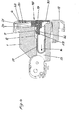
Ein Ausführungsbeispiel der Erfindung ist in der Zeichnung dargestellt und wird im Folgenden näher beschrieben. Es zeigenAn embodiment of the invention is illustrated in the drawing and will be described in more detail below. Show it
Der dargestellte Fahrtschreiber weist ein Gehäuse
Es wird darauf hingewiesen, dass alle im Folgenden beschriebenen Elemente an einem Seitenbereich der Papierboxeinheit
Am inneren Ende des Aufnahmeschachts
In einem Abstand zur Mündungsöffnung
In der Seitenwand
An der Seitenwand
Die Papierboxeinheit
Die Papierboxblende
Mit dem Seitenbereich der Papierboxblende
An dem Gehäuse
Mit dem Verschwenken der Papierboxblende
Kommt dabei die Aufdrücknase
Nun kann die Papierboxeinheit
Wird nun die Papierboxeinheit
Wird die Papierboxeinheit
Die Schließdruckfläche
Bei einem weiteren Einschieben der Papierboxeinheit
An dem umlaufenden Rand der Papierboxblende
Die Mündungsöffnung
Claims (9)
Priority Applications (2)
| Application Number | Priority Date | Filing Date | Title |
|---|---|---|---|
| DE102016214173.2A DE102016214173A1 (en) | 2016-08-01 | 2016-08-01 | tachograph |
| EP17183765.1A EP3279872B1 (en) | 2016-08-01 | 2017-07-28 | Tachograph |
Applications Claiming Priority (1)
| Application Number | Priority Date | Filing Date | Title |
|---|---|---|---|
| DE102016214173.2A DE102016214173A1 (en) | 2016-08-01 | 2016-08-01 | tachograph |
Publications (1)
| Publication Number | Publication Date |
|---|---|
| DE102016214173A1 true DE102016214173A1 (en) | 2018-02-01 |
Family
ID=59501278
Family Applications (1)
| Application Number | Title | Priority Date | Filing Date |
|---|---|---|---|
| DE102016214173.2A Ceased DE102016214173A1 (en) | 2016-08-01 | 2016-08-01 | tachograph |
Country Status (2)
| Country | Link |
|---|---|
| EP (1) | EP3279872B1 (en) |
| DE (1) | DE102016214173A1 (en) |
Cited By (1)
| Publication number | Priority date | Publication date | Assignee | Title |
|---|---|---|---|---|
| CN119035095A (en) * | 2024-11-01 | 2024-11-29 | 山东汇川机电设备有限公司 | Workbench for carrier roller detection and use method |
Citations (6)
| Publication number | Priority date | Publication date | Assignee | Title |
|---|---|---|---|---|
| DE29904801U1 (en) * | 1999-03-16 | 1999-06-02 | Mannesmann VDO AG, 60388 Frankfurt | Read / write unit for data cards |
| DE10321225A1 (en) * | 2003-05-12 | 2004-12-23 | Siemens Ag | printer |
| EP1575000A1 (en) * | 2004-03-02 | 2005-09-14 | Delphi Technologies, Inc. | Tachograph with exchangeable printer |
| DE102009058186A1 (en) * | 2009-12-15 | 2011-06-16 | Continental Automotive Gmbh | Tachograph i.e. digital tachograph, for use at shaft of dashboard of motor vehicle, has feed opening, which is opened in feeding position of carrier, is closed in operating position, and is led transverse to motion direction of carrier |
| DE102007037444B4 (en) * | 2007-08-08 | 2011-07-21 | Continental Automotive GmbH, 30165 | tachograph |
| US20120155006A1 (en) * | 2010-12-20 | 2012-06-21 | Continental Automotive Gmbh | Onboard Information System For Vehicles |
Family Cites Families (3)
| Publication number | Priority date | Publication date | Assignee | Title |
|---|---|---|---|---|
| DE29812216U1 (en) * | 1998-07-09 | 1998-09-10 | Mannesmann VDO AG, 60388 Frankfurt | Tachograph with a rectangular installation housing and with a printing device |
| AT506071B1 (en) * | 2008-01-15 | 2009-06-15 | Efkon Mobility Gmbh | PRINTING DIRECTION |
| EP2610816B1 (en) * | 2011-12-28 | 2021-04-21 | Stoneridge Electronics AB | Vehicle unit with integrated antenna |
-
2016
- 2016-08-01 DE DE102016214173.2A patent/DE102016214173A1/en not_active Ceased
-
2017
- 2017-07-28 EP EP17183765.1A patent/EP3279872B1/en active Active
Patent Citations (6)
| Publication number | Priority date | Publication date | Assignee | Title |
|---|---|---|---|---|
| DE29904801U1 (en) * | 1999-03-16 | 1999-06-02 | Mannesmann VDO AG, 60388 Frankfurt | Read / write unit for data cards |
| DE10321225A1 (en) * | 2003-05-12 | 2004-12-23 | Siemens Ag | printer |
| EP1575000A1 (en) * | 2004-03-02 | 2005-09-14 | Delphi Technologies, Inc. | Tachograph with exchangeable printer |
| DE102007037444B4 (en) * | 2007-08-08 | 2011-07-21 | Continental Automotive GmbH, 30165 | tachograph |
| DE102009058186A1 (en) * | 2009-12-15 | 2011-06-16 | Continental Automotive Gmbh | Tachograph i.e. digital tachograph, for use at shaft of dashboard of motor vehicle, has feed opening, which is opened in feeding position of carrier, is closed in operating position, and is led transverse to motion direction of carrier |
| US20120155006A1 (en) * | 2010-12-20 | 2012-06-21 | Continental Automotive Gmbh | Onboard Information System For Vehicles |
Cited By (1)
| Publication number | Priority date | Publication date | Assignee | Title |
|---|---|---|---|---|
| CN119035095A (en) * | 2024-11-01 | 2024-11-29 | 山东汇川机电设备有限公司 | Workbench for carrier roller detection and use method |
Also Published As
| Publication number | Publication date |
|---|---|
| EP3279872B1 (en) | 2019-09-11 |
| EP3279872A1 (en) | 2018-02-07 |
Similar Documents
| Publication | Publication Date | Title |
|---|---|---|
| DE102011001740B4 (en) | Slide rail for a vehicle seat and vehicle seat with such a slide rail | |
| EP3253604B1 (en) | Arrangement comprising a cover for a vehicle roof | |
| EP3670102A1 (en) | Stackable case, arrangement with two cases placed one on top of the other and use of a case | |
| DE102017201283B4 (en) | LOCKING DEVICE FOR A SLIDING DOOR | |
| DE2423969A1 (en) | LENGTH ADJUSTMENT DEVICE FOR VEHICLE SEATS | |
| EP3478533A1 (en) | Longitudinal adjuster and vehicle seat | |
| DE202014005799U1 (en) | Motor vehicle tank flap arrangement | |
| DE102015108395A1 (en) | Retaining element for a vehicle hood | |
| EP2707249B1 (en) | Longitudinally adjustable vehicle seat with a memory device | |
| DE202007000112U1 (en) | Locking arrangement with a pivotable locking hook and a sliding support rod | |
| DE102016214173A1 (en) | tachograph | |
| DE102017100742B3 (en) | Lockable coupling device | |
| EP3356629A1 (en) | Fitting for a sliding door and method for assembling a sliding door | |
| DE202013003241U1 (en) | Fixing device for a sliding door of a motor vehicle | |
| DE102018120509B4 (en) | Lashing point with opening for inserting an eyelet body | |
| DE10343391B3 (en) | Inspection covering for providing access to e.g. electrical or sanitary installations comprises a cover-side hinge arm that has a lateral centering arm with a centering recess for centering lugs fixed on a frame | |
| EP0090956A1 (en) | Mounting for a window, a door or the like | |
| DE102017100688B4 (en) | Device for fixing a brake shoe, braking device and method for fixing a brake shoe | |
| DE102015111300B4 (en) | Vehicle sunroof | |
| DE102020111061B4 (en) | Windshield wiper system for a motor vehicle | |
| DE102018119299A1 (en) | Heavy duty extract | |
| DE10017236C2 (en) | Automatically lockable and detachable connection assembly, in particular for connecting two sea freight containers arranged one above the other | |
| DE8700209U1 (en) | Electrical connector that can be locked into a mounting wall opening | |
| DE3622915A1 (en) | Belt buckle | |
| DE19817422C1 (en) | Installation system for a bath tub or shower tray |
Legal Events
| Date | Code | Title | Description |
|---|---|---|---|
| R012 | Request for examination validly filed | ||
| R079 | Amendment of ipc main class |
Free format text: PREVIOUS MAIN CLASS: G07C0005080000 Ipc: G01P0001120000 |
|
| R002 | Refusal decision in examination/registration proceedings | ||
| R003 | Refusal decision now final |