DE102016202340A1 - Measuring device and measuring method - Google Patents
Measuring device and measuring method Download PDFInfo
- Publication number
- DE102016202340A1 DE102016202340A1 DE102016202340.3A DE102016202340A DE102016202340A1 DE 102016202340 A1 DE102016202340 A1 DE 102016202340A1 DE 102016202340 A DE102016202340 A DE 102016202340A DE 102016202340 A1 DE102016202340 A1 DE 102016202340A1
- Authority
- DE
- Germany
- Prior art keywords
- measuring
- measuring device
- deformation
- signal
- component
- Prior art date
- Legal status (The legal status is an assumption and is not a legal conclusion. Google has not performed a legal analysis and makes no representation as to the accuracy of the status listed.)
- Ceased
Links
- 238000000034 method Methods 0.000 title claims abstract description 21
- 238000005096 rolling process Methods 0.000 claims description 50
- 238000005259 measurement Methods 0.000 claims description 14
- 238000001514 detection method Methods 0.000 claims description 13
- 230000008859 change Effects 0.000 claims description 11
- 238000011156 evaluation Methods 0.000 claims description 6
- 230000009466 transformation Effects 0.000 claims description 6
- 239000013078 crystal Substances 0.000 claims description 5
- 230000000737 periodic effect Effects 0.000 claims description 4
- 230000008569 process Effects 0.000 claims description 4
- 230000005540 biological transmission Effects 0.000 claims 1
- 238000001228 spectrum Methods 0.000 description 9
- 238000004458 analytical method Methods 0.000 description 8
- 238000001914 filtration Methods 0.000 description 7
- 230000035939 shock Effects 0.000 description 6
- 238000012360 testing method Methods 0.000 description 5
- 238000004364 calculation method Methods 0.000 description 4
- 238000012545 processing Methods 0.000 description 3
- 230000005236 sound signal Effects 0.000 description 3
- 230000001133 acceleration Effects 0.000 description 2
- 239000000919 ceramic Substances 0.000 description 2
- 238000005094 computer simulation Methods 0.000 description 2
- 230000007547 defect Effects 0.000 description 2
- 238000009434 installation Methods 0.000 description 2
- 230000010355 oscillation Effects 0.000 description 2
- 239000011241 protective layer Substances 0.000 description 2
- 230000035945 sensitivity Effects 0.000 description 2
- 239000007787 solid Substances 0.000 description 2
- 239000004593 Epoxy Substances 0.000 description 1
- 208000010201 Exanthema Diseases 0.000 description 1
- 238000009825 accumulation Methods 0.000 description 1
- 239000000853 adhesive Substances 0.000 description 1
- 230000001070 adhesive effect Effects 0.000 description 1
- 230000008901 benefit Effects 0.000 description 1
- 230000015572 biosynthetic process Effects 0.000 description 1
- 238000010276 construction Methods 0.000 description 1
- 125000004122 cyclic group Chemical group 0.000 description 1
- 238000011157 data evaluation Methods 0.000 description 1
- 230000003247 decreasing effect Effects 0.000 description 1
- 230000002950 deficient Effects 0.000 description 1
- 238000006073 displacement reaction Methods 0.000 description 1
- 230000000694 effects Effects 0.000 description 1
- 238000005516 engineering process Methods 0.000 description 1
- 201000005884 exanthem Diseases 0.000 description 1
- 239000003365 glass fiber Substances 0.000 description 1
- 238000009532 heart rate measurement Methods 0.000 description 1
- 230000010354 integration Effects 0.000 description 1
- 239000010410 layer Substances 0.000 description 1
- 239000000463 material Substances 0.000 description 1
- 238000012544 monitoring process Methods 0.000 description 1
- 239000002245 particle Substances 0.000 description 1
- 206010037844 rash Diseases 0.000 description 1
- 238000004088 simulation Methods 0.000 description 1
- 230000000638 stimulation Effects 0.000 description 1
Images


Classifications
-
- G—PHYSICS
- G01—MEASURING; TESTING
- G01B—MEASURING LENGTH, THICKNESS OR SIMILAR LINEAR DIMENSIONS; MEASURING ANGLES; MEASURING AREAS; MEASURING IRREGULARITIES OF SURFACES OR CONTOURS
- G01B7/00—Measuring arrangements characterised by the use of electric or magnetic techniques
- G01B7/16—Measuring arrangements characterised by the use of electric or magnetic techniques for measuring the deformation in a solid, e.g. by resistance strain gauge
-
- F—MECHANICAL ENGINEERING; LIGHTING; HEATING; WEAPONS; BLASTING
- F16—ENGINEERING ELEMENTS AND UNITS; GENERAL MEASURES FOR PRODUCING AND MAINTAINING EFFECTIVE FUNCTIONING OF MACHINES OR INSTALLATIONS; THERMAL INSULATION IN GENERAL
- F16C—SHAFTS; FLEXIBLE SHAFTS; ELEMENTS OR CRANKSHAFT MECHANISMS; ROTARY BODIES OTHER THAN GEARING ELEMENTS; BEARINGS
- F16C19/00—Bearings with rolling contact, for exclusively rotary movement
- F16C19/52—Bearings with rolling contact, for exclusively rotary movement with devices affected by abnormal or undesired conditions
- F16C19/527—Bearings with rolling contact, for exclusively rotary movement with devices affected by abnormal or undesired conditions related to vibration and noise
-
- G—PHYSICS
- G01—MEASURING; TESTING
- G01H—MEASUREMENT OF MECHANICAL VIBRATIONS OR ULTRASONIC, SONIC OR INFRASONIC WAVES
- G01H1/00—Measuring characteristics of vibrations in solids by using direct conduction to the detector
- G01H1/003—Measuring characteristics of vibrations in solids by using direct conduction to the detector of rotating machines
-
- G—PHYSICS
- G01—MEASURING; TESTING
- G01H—MEASUREMENT OF MECHANICAL VIBRATIONS OR ULTRASONIC, SONIC OR INFRASONIC WAVES
- G01H11/00—Measuring mechanical vibrations or ultrasonic, sonic or infrasonic waves by detecting changes in electric or magnetic properties
- G01H11/06—Measuring mechanical vibrations or ultrasonic, sonic or infrasonic waves by detecting changes in electric or magnetic properties by electric means
- G01H11/08—Measuring mechanical vibrations or ultrasonic, sonic or infrasonic waves by detecting changes in electric or magnetic properties by electric means using piezoelectric devices
-
- G—PHYSICS
- G01—MEASURING; TESTING
- G01L—MEASURING FORCE, STRESS, TORQUE, WORK, MECHANICAL POWER, MECHANICAL EFFICIENCY, OR FLUID PRESSURE
- G01L5/00—Apparatus for, or methods of, measuring force, work, mechanical power, or torque, specially adapted for specific purposes
- G01L5/0004—Force transducers adapted for mounting in a bore of the force receiving structure
-
- G—PHYSICS
- G01—MEASURING; TESTING
- G01L—MEASURING FORCE, STRESS, TORQUE, WORK, MECHANICAL POWER, MECHANICAL EFFICIENCY, OR FLUID PRESSURE
- G01L5/00—Apparatus for, or methods of, measuring force, work, mechanical power, or torque, specially adapted for specific purposes
- G01L5/0009—Force sensors associated with a bearing
- G01L5/0019—Force sensors associated with a bearing by using strain gages, piezoelectric, piezo-resistive or other ohmic-resistance based sensors
-
- F—MECHANICAL ENGINEERING; LIGHTING; HEATING; WEAPONS; BLASTING
- F16—ENGINEERING ELEMENTS AND UNITS; GENERAL MEASURES FOR PRODUCING AND MAINTAINING EFFECTIVE FUNCTIONING OF MACHINES OR INSTALLATIONS; THERMAL INSULATION IN GENERAL
- F16C—SHAFTS; FLEXIBLE SHAFTS; ELEMENTS OR CRANKSHAFT MECHANISMS; ROTARY BODIES OTHER THAN GEARING ELEMENTS; BEARINGS
- F16C2233/00—Monitoring condition, e.g. temperature, load, vibration
-
- G—PHYSICS
- G01—MEASURING; TESTING
- G01M—TESTING STATIC OR DYNAMIC BALANCE OF MACHINES OR STRUCTURES; TESTING OF STRUCTURES OR APPARATUS, NOT OTHERWISE PROVIDED FOR
- G01M13/00—Testing of machine parts
- G01M13/04—Bearings
- G01M13/045—Acoustic or vibration analysis
Landscapes
- Physics & Mathematics (AREA)
- General Physics & Mathematics (AREA)
- Engineering & Computer Science (AREA)
- General Engineering & Computer Science (AREA)
- Mechanical Engineering (AREA)
- Chemical & Material Sciences (AREA)
- Analytical Chemistry (AREA)
- Testing Of Devices, Machine Parts, Or Other Structures Thereof (AREA)
Abstract
Die Erfindung betrifft eine Messvorrichtung zur Erfassung von Körperschall und einer Verformung an einem System mit mindestens einem ersten Bauelement des Systems, das sich relativ zu mindestens einem zweiten Bauelement des Systems unter Last bewegt, gekennzeichnet durch mindestens ein Messelement (1), das so eingerichtet und ausgebildet ist, dass damit Körperschall und Verformung gemeinsam messbar sind. Die Erfindung betrifft auch ein Messverfahren.The invention relates to a measuring device for detecting structure-borne noise and deformation on a system with at least one first component of the system, which moves relative to at least one second component of the system under load, characterized by at least one measuring element (1), which is set up and is formed so that structure-borne noise and deformation can be measured together. The invention also relates to a measuring method.
Description
Die Erfindung betrifft eine Messvorrichtung mit den Merkmalen des Anspruchs 1 und ein Messverfahren mit den Merkmalen des Anspruchs 13. The invention relates to a measuring device having the features of
In vielen Systemen mit beweglichen Bauelementen ist es wichtig, das Versagen der Bauelemente zu erfassen, aber insbesondere auch, das Versagen der Bauelemente vorherzusagen. In many systems with moving components, it is important to detect the failure of the components, but in particular, to predict the failure of the components.
Es ist bekannt, den Körperschall eines Systems, wie z.B. eines Wälzlagers, zu analysieren, um den Verschleiß zu beurteilen. Dazu werden z.B. eingebettete Piezoelemente (piezoelektrische oder piezoresistive Sensorelemente) eingesetzt. Der Wälzlagerverschleiß ergibt sich dann auf Grund periodischer oder quasi-periodischer Signale. Schäden, wie z.B. das Überrollen der Wälzkörper von Defekten auf den Laufflächen, können so erkannt werden. It is known to use the structure-borne noise of a system, such as a rolling bearing, analyze to assess the wear. For this, e.g. embedded piezoelectric elements (piezoelectric or piezoresistive sensor elements) used. The rolling bearing wear is then due to periodic or quasi-periodic signals. Damage, such as The rolling over of rolling elements from defects on the running surfaces can thus be recognized.
Die Aufgabe wird durch eine Messvorrichtung mit den Merkmalen des Anspruchs 1 gelöst. The object is achieved by a measuring device with the features of
Dabei erfasst die Messvorrichtung Körperschall und Verformung gleichzeitig an einem System mit mindestens einem ersten Bauelement, das sich relativ zu mindestens einem zweiten Bauelement unter Last bewegt. In this case, the measuring device detects structure-borne noise and deformation simultaneously on a system with at least one first component that moves relative to at least one second component under load.
Dabei ist mindestens ein Messelement so eingerichtet und ausgebildet, dass damit Körperschall und Verformung gemeinsam messbar sind. Damit ist die Erfassung von unterschiedlichen, aber für die Beurteilung des Systemzustands wichtigen, Frequenzbereichen möglich. In this case, at least one measuring element is set up and designed such that structure-borne noise and deformation can be measured together. This makes it possible to record different frequency ranges that are important for assessing the system status.
Dabei sind in einer Ausführungsform Körperschall im Frequenzbereich bis 5 MHz, insbesondere bis 2 MHz und Verformungen hinunter bis zu 0.1 Hz messbar. Die Frequenzbereiche können damit mehr als sechs Größenordnungen auseinanderliegen. In one embodiment, structure-borne noise in the frequency range up to 5 MHz, in particular up to 2 MHz, and deformations down to 0.1 Hz can be measured. The frequency ranges can thus be more than six orders of magnitude apart.
In einer Ausführungsform sind der Körperschall und die Verformung durch mindestens ein Piezoelement erfassbar. Insbesondere kann dabei das mindestens eine Piezoelement ein piezoelektrisches Element, ein piezoresistives Element, eine Dehnungsmessbrücke oder eine Messbrücke mit piezoresistiven Elementen aufweisen. In one embodiment, the structure-borne noise and the deformation can be detected by at least one piezoelectric element. In particular, the at least one piezoelectric element can have a piezoelectric element, a piezoresistive element, a strain gauge bridge or a measuring bridge with piezoresistive elements.
Zusätzlich oder alternativ weist das mindestens eine Messelement ein trägheitsfreies Messprinzip auf, wobei insbesondere ein Piezokristall verformt wird. Somit ist es nicht erforderlich, dass das Messelement eine Beschleunigungsmasse aufweist. Additionally or alternatively, the at least one measuring element has an inertia-free measuring principle, wherein in particular a piezoelectric crystal is deformed. Thus, it is not necessary that the measuring element has an acceleration mass.
In einer weiteren Ausführungsform ist das mindestens eine Piezoelement in ein festes Bauteil des Systems, insbesondere einen Außenring eines Wälzlagers, eingebettet oder als geschlossenes, separates Bauteil angebaut. In a further embodiment, the at least one piezoelement is embedded in a fixed component of the system, in particular an outer ring of a roller bearing, or mounted as a closed, separate component.
Auch ist es möglich, aus dem erfassten Körperschall und der erfassten Verformung ein Messsignal, insbesondere ein Muster, in Abhängigkeit einer Abweichung von der regulären Form eines Lastwechsels (d.h. der Lastwechsel wird als die periodische Überrollung des Sensorareals aufgefasst), zu generieren, wobei die Abweichung insbesondere repräsentativ für die Feststellung mindestens eines Schadens des Systems und / oder der Bauelemente ist. Die gleichzeitige Erfassung von Körperschall und Verformung erlaubt eine umfassende Kontrolle des zu prüfenden Systems. Dies bedeutet, dass das mindestens eine Messelement eingerichtet und ausgebildet ist, eine solche Abweichung zu erfassen. It is also possible to generate from the detected structure-borne sound and the detected deformation a measurement signal, in particular a pattern, as a function of a deviation from the regular shape of a load change (ie the load change is considered as the periodic roll over of the sensor area), the deviation particularly representative of the finding of at least one damage of the system and / or components. The simultaneous detection of structure-borne noise and deformation allows comprehensive control of the system under test. This means that the at least one measuring element is set up and designed to detect such a deviation.
Auch ist es möglich, dass der Lastwechsel in einer Änderung eines am System angreifenden Momentes und / oder einer am System angreifenden Kraft resultiert. It is also possible that the load change results in a change in a system-engaging torque and / or a system-applied force.
Typischerweise kann das System ein Lager, ein Wälzlager und / oder Getriebe sein oder solche Teile aufweisen. In allen diesen Ausführungsformen sind mindestens zwei Bauelemente vorhanden, die sich unter Last relativ zueinander bewegen. Typically, the system may be a bearing, a rolling bearing and / or gear or have such parts. In all of these embodiments, there are at least two components that move relative to each other under load.
Das Signal besteht aus Überrollsignal plus einem höherfrequenten Schadsignal (falls ein Schaden vorhanden ist). Bei der Anwendung auf ein Wälzlager ist in einer Ausführungsform ein Signal der Wälzkörper ermittelbar, wobei der Überrollanteil dominiert. Es ist ein Filtermittel dazu vorgesehen ist, das höherfrequente Schadsignal aus dem Signal zu ermitteln. Dabei kann insbesondere mindestens ein Filterparameter des Filtermittels durch eine Auswertung des Überrollsignals ermittelbar sein. The signal consists of a rollover signal plus a higher-frequency damage signal (if there is damage). When applied to a rolling bearing in one embodiment, a signal of the rolling elements can be determined, wherein the rollover portion dominates. It is a filter means is provided to determine the higher-frequency damage signal from the signal. In this case, in particular at least one filter parameter of the filter means can be determined by an evaluation of the rollover signal.
Die Aufgabe wird auch durch ein Messverfahren nach Anspruch 13 gelöst. The object is also achieved by a measuring method according to claim 13.
Dabei werden mit mindestens einem Messelement der Körperschall und eine Verformung zusammen und im Wesentlichen gleichzeitig erfasst. In this case, the structure-borne noise and a deformation are detected together and essentially simultaneously with at least one measuring element.
Insbesondere kann in einer Ausführungsform aus dem erfassten Körperschall und der erfassten Verformung ein Messsignal, insbesondere ein Muster, in Abhängigkeit einer Abweichung von der regulären Form des Lastwechsels generiert werden, wobei die Abweichung insbesondere repräsentativ für die Feststellung mindestens eines Schadens des Systems und / oder der Bauelemente ist. In particular, in one embodiment, a measured signal, in particular a pattern, can be generated as a function of a deviation from the regular shape of the load alternation from the recorded structure-borne noise and the detected deformation, wherein the deviation is particularly representative of the detection of at least one damage of the system and / or the Components is.
Die Auswertung abklingender Eigenfrequenzen kann insbesondere unter Verwendung von Hüllkurven, z.B. ermittelt mit der Hilbert-Transformation, erfolgen. The evaluation of evanescent natural frequencies can be carried out in particular using envelopes, e.g. determined using the Hilbert transformation.
Aus dem Signal kann nach einer Fourier-Transformation die Auswertung von Seitenbändern zur Feststellung von periodischen Vorgängen erfolgen. From the signal, after a Fourier transformation, the evaluation of sidebands to determine periodic processes can take place.
Auch ist es möglich, dass eine Messung von Lasten erfolgt, die das Bauelement bis in den plastischen Bereich belasten. It is also possible that a measurement of loads takes place, which load the component into the plastic area.
Die Messvorrichtung und / oder das Messverfahren können in einer Turbomaschine, insbesondere einem Flugzeugtriebwerk, verwendet werden. The measuring device and / or the measuring method can be used in a turbomachine, in particular an aircraft engine.
Ausführungsbeispiele werden anhand von Figuren näher beschrieben. Dabei zeigt Embodiments will be described with reference to figures. It shows
Im Folgenden werden die Ausführungsformen der Messvorrichtung und des Messverfahrens anhand von Beispielen, nämlich der Datenerfassung an einem Wälzlager, beschrieben. Das Wälzlager ist ein System, in dem sich ein erstes Bauelement (hier z.B. eine Kugel) unter Last relativ zu einem zweiten Bauelement (hier Laufbahn des Wälzlagerings) bewegt. In the following, the embodiments of the measuring device and the measuring method will be described by means of examples, namely the data acquisition on a roller bearing. The rolling bearing is a system in which a first component (here, for example, a ball) moves under load relative to a second component (in this case, a raceway of the rolling bearing ring).
Dabei geht es um die Erkennung von kleinen oder kleinsten Schäden in einem Wälzlager, insbesondere einem Kugellager. Das Überrollen eines Schadens verursacht einen Puls mit einer hohen Bandbreite. Dieser Puls regt die Eigenfrequenzen der umgebenden Strukturen an, die z.T. sehr hoch sein können. Diese Frequenzen können von einem Piezoelement
Grundsätzlich können die hier beschriebenen Vorrichtungen und Verfahren auch bei anderen Wälzlagern verwendet werden, wie z.B. radialem Rollenlager, Kugellager, Nadellager, Zylinderrollenlager oder Tonnenlager. Auch können damit Schrägkugellager oder Axiallager untersucht werden. In principle, the devices and methods described herein may also be used with other roller bearings, such as those described in US Pat. radial roller bearings, ball bearings, needle roller bearings, cylindrical roller bearings or roller bearings. Also angular contact ball bearings or thrust bearings can be examined.
In jedem Fall ist ein Wälzlager ein System, bei dem sich Bauelemente (Außenringe
Dabei ist die Erkennung von Schäden auf einer Kugel (oder allgemeiner einem Wälzkörper
1. Aufbau und Installation eines Messelementes 1. Construction and installation of a measuring element
In der Anwendung in einem Schrägkugellager
Die Messelemente
Dies ist eine mögliche Form einer Einbettung eines Messelementes
Die Piezoelemente
2. Funktionsprinzip und Fehlererkennungsmethoden 2. Function principle and error detection methods
Im polarisierten Piezokristall des Piezoelementes
Durch die Verwendung von Piezoelementen
Im piezoresistiven Kristall des Piezoelementes
Körperschall bei Schadüberrollung (siehe Abschnitt 2.1) Structure-borne noise in case of damage overrun (see section 2.1)
Bei der Überrollung eines Schadens, entweder auf der Kugel oder den Lagerringen, erfolgt ein Energieeintrag. Der entstandene Körperschall ist mit einem Piezoelement
Zyklische Überrollung (Verformung, siehe Abschnitt 2.2) Cyclic rollover (deformation, see section 2.2)
Bestimmung der Käfigdrehzahl, aber auch der Wellendrehzahl und kleinste Unwucht werden dadurch ermöglicht. Die Amplitude der Überrollung lässt auf das Maß der Verformung und somit auf die Lagerlast rückschließen. Durch das Überrollsignal ist eine fortlaufende Funktionsprüfung der Messkette möglich. Determining the cage speed, but also the shaft speed and smallest imbalance are made possible. The amplitude of the rollover suggests the degree of deformation and thus the bearing load. Due to the rollover signal, a continuous function test of the measuring chain is possible.
Somit ist es möglich, Körperschall und Verformungen gemeinsam im System, hier also einem Wälzlager
Bei der Anwendung in Flugzeugtriebwerken kann die Verformungsfrequenz als Käfigfrequenz mal Kugelanzahl angenommen werden. Die Käfigfrequenz ist kleiner als die halbe Drehzahl der Welle. Der Körperschall weist eine viel höhere Frequenz auf, in der Regel über 10 KHz. When used in aircraft engines, the deformation frequency can be assumed to be the cage frequency times the number of balls. The cage frequency is less than half the speed of the shaft. The structure-borne noise has a much higher frequency, usually over 10 KHz.
2.1 Schadenserkennung durch Körperschallmessung 2.1 Damage detection by structure-borne noise measurement
Bei der Überrollung von Schäden oder Partikeln im Kugellager
Dieser Stoß selbst ist messtechnisch nur sehr schwer erfassbar, regt jedoch Eigenfrequenzen von umliegenden schwingfähigen Strukturen an. Angeregte Eigenfrequenzen sind als abklingende Schwingungen gut durch das Messelement
2.1.1 Hochpassfilterung der Signale der Piezoelemente 2.1.1 High-pass filtering of the signals of the piezo elements
Die Signale, die bei der Überrollung im Bereich der Piezoelemente
Für eine Ermittlung der Körperschallsignale auf den Überrollsignalen ist eine Filterung mit einem Filtermittel
In
2.1.2 Hüllkurvenerfassung 2.1.2 Envelope detection
Bei der Schadüberrollung einer defekten Komponente im Wälzlager
Die wichtige Information über den Schaden ist in der Wiederholfrequenz der angeregten schnell abklingenden Schwingungen der Eigenfrequenzen enthalten (
Um die Wiederholfrequenz erhalten zu können, wird die Hüllkurve (Kurve c) in
Dabei ist schematisch ein Wälzlager
Im Teil a) der
Dieses Signal kann dann einer Frequenzanalyse (z.B. Analyse der Hüllkurve mittels FFT) unterzogen werden, die z.B. in der Messvorrichtung
Der Abstand der Moden wird durch die Größe fAR bestimmt, deren Größe von der Drehzahl, der Kugelanzahl z, dem Kontaktwinkel α und dem Durchmesserverhältnis Dpw / Dw, d.h. dem Verhältnis von Kugeldurchmesser und Durchmesser des Kreises, auf dem die Wälzkörpermittelpunkte liegen, abhängt. The distance of the modes is determined by the size f AR whose size depends on the rotational speed, the number of balls z, the contact angle α and the diameter ratio D pw / D w , ie the ratio of ball diameter and diameter of the circle on which the rolling element centers lie. depends.
Da nicht über rein-theoretische Überlegungen die Eigenfrequenzen ausgearbeitet werden können, müssen diese messtechnisch bestimmt werden. Es ist dann möglich, Durchlassfrequenzen derart zu setzen, dass möglichst nur die Eigenfrequenz durchgelassen wird, die für die entsprechende Überwachung von Interesse ist. Es ist dabei allerdings zu beachten, dass sich diese Eigenfrequenz entsprechend der Betriebsbedingungen und der Betriebsdauer verschieben kann. Das optimale Setzen der Frequenzen ist jedoch eine Möglichkeit, die zahlreich vorhandenen Störfrequenzen eines Flugzeugtriebwerks von Beginn an nach Möglichkeit auszublenden. Since the eigenfrequencies can not be worked out beyond purely theoretical considerations, these must be determined by measurement. It is then possible to set pass frequencies such that as far as possible only the natural frequency is passed, which is of interest for the corresponding monitoring. However, it should be noted that this natural frequency can shift according to the operating conditions and the operating time. The optimum setting of the frequencies, however, is one way to hide the numerous existing noise frequencies of an aircraft engine from the beginning, if possible.
2.1.3 Seitenbänder und Höherharmonische 2.1.3 Sidebands and higher harmonics
2.1.3.1 Seitenbänder 2.1.3.1 Sidebands
Die Messelemente
Der Abstand der Seitenbänder ergibt zusammen mit den Mittenfrequenzen eine Information über das Lagerelement (Innenring, Außenring), das geschädigt ist. The spacing of the sidebands together with the center frequencies gives information about the bearing element (inner ring, outer ring) which has been damaged.
2.1.4 Test-Ergebnisse 2.1.4 Test results
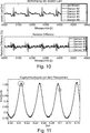
Es ist anhand der Überrollereignisse (Kreuze als unterste Messwerte in
2.2 Käfigdrehzahl-/ Wellendrehzahlmessung und Lagerlastbestimmung 2.2 Cage speed / shaft speed measurement and bearing load determination
Die zyklische Überrollung des Außenrings
In den einzelnen Abbildungen der
Der obere Teil der
Das entsprechende Spektrum des Überrollsignals ist im unteren Teil der
Die Seitenbänder um die Moden des Spektrums weisen den Abstand +/–c (Wellendrehzahl) auf, wobei das gesamte Spektrum um +c gegenüber dem Nullpunkt verschoben ist. Die Seitenbänder stammen von minimalen Exzentrizitäten (Unwucht) der Welle. The sidebands around the modes of the spectrum have the distance +/- c (shaft speed) with the entire spectrum shifted + c relative to the zero point. The sidebands are derived from minimal eccentricities (imbalance) of the shaft.
Jeder Wellenberg stellt einen vorbeirollenden Wälzkörper
Die Überrollung des Schadens erfolgt in räumlich unterschiedlichen Abständen zum Messelement
Es ist ebenfalls möglich, aus der Signalamplitude, respektive der Verformung, (siehe
Die Lastabschätzung wird in Zusammenhang mit der
Eingangsgrößen für den Lastschätzer sind die Temperatur von Laufringen eines Wälzlagers, die vom Piezoelement erfassten Amplituden und die Käfigfrequenz. Die Ausgangsgröße des Lastschätzers ist die Axialkraft auf die Laufringe des Wälzlagers. Input variables for the load estimator are the temperature of races of a rolling bearing, the amplitudes detected by the piezo element and the cage frequency. The output variable of the load estimator is the axial force on the races of the rolling bearing.
Das Rechenmodell kann z.B. einen Polynomansatz zweiter Ordnung umfassen. Mittels einer Fehlerquadratminimierung können die Parameter, d.h. die Koeffizienten des Polynomansatzes, bestimmt werden. The computational model may e.g. comprise a second order polynomial clause. By means of least squares minimization, the parameters, i. the coefficients of the polynomial sentence are determined.
In
In
2.3 Lebensdauerbestimmung 2.3 Lifetime determination
Das Konzept zur Bestimmung der Lagerlebensdauer bestimmt den Lagerzustand anhand der Akkumulation aller Schäden, unter Berücksichtigung der Lagerlast, sowie der Materialkennwerte und prognostiziert daraus die verbleibende Lebensdauer. Das Messelement
Die geringe Abmessung des Messelements
Der Piezokristall des Piezoelementes
Da das Messelement
Auch wenn die Messvorrichtung und das Messverfahren anhand einer Ausführungsform eines Wälzlagers beschrieben wurden, so können beide auch im Zusammenhang mit anderen Systemen, z.B. Getrieben oder anderen Lagern, verwendet werden. Although the measuring apparatus and method have been described with reference to one embodiment of a rolling bearing, both may also be used in conjunction with other systems, e.g. Geared or other bearings.
BezugszeichenlisteLIST OF REFERENCE NUMBERS
- 1 1
- Messelement measuring element
- 2 2
- Piezoelement, piezoelektrisches Element Piezo element, piezoelectric element
- 3 3
- Schutzschicht protective layer
- 4 4
- Befestigungsmittel fastener
- 5 5
- Nut groove
- 10 10
- Bauelement, Wälzlager Component, rolling bearings
- 11 11
- Außenring Wälzlager Outer ring rolling bearings
- 12 12
- Innenring Wälzlager Inner ring roller bearings
- 15 15
- Wälzkörper rolling elements
- 20 20
- Messvorrichtung, Datenverarbeitungsvorrichtung Measuring device, data processing device
- 21 21
- Filtermittel filter means
Claims (18)
Applications Claiming Priority (2)
| Application Number | Priority Date | Filing Date | Title |
|---|---|---|---|
| DE102015214074.1 | 2015-07-24 | ||
| DE102015214074 | 2015-07-24 |
Publications (1)
| Publication Number | Publication Date |
|---|---|
| DE102016202340A1 true DE102016202340A1 (en) | 2017-01-26 |
Family
ID=57738895
Family Applications (1)
| Application Number | Title | Priority Date | Filing Date |
|---|---|---|---|
| DE102016202340.3A Ceased DE102016202340A1 (en) | 2015-07-24 | 2016-02-16 | Measuring device and measuring method |
Country Status (1)
| Country | Link |
|---|---|
| DE (1) | DE102016202340A1 (en) |
Cited By (6)
| Publication number | Priority date | Publication date | Assignee | Title |
|---|---|---|---|---|
| DE102017206760A1 (en) * | 2017-04-21 | 2018-10-25 | Rolls-Royce Deutschland Ltd & Co Kg | Method and device for determining damage, wear and / or imbalance in a gearbox, in particular a planetary gearbox |
| DE102018112200A1 (en) * | 2018-05-22 | 2019-11-28 | Minebea Mitsumi Inc. | Rolling device |
| CN110823575A (en) * | 2019-11-09 | 2020-02-21 | 北京工业大学 | Bearing life prediction method based on performance degradation dictionary structure and similarity |
| DE102019207256A1 (en) * | 2019-05-17 | 2020-11-19 | Rolls-Royce Deutschland Ltd & Co Kg | Device and method for self-diagnosis of a monitoring device of a component |
| US20210131308A1 (en) * | 2019-11-04 | 2021-05-06 | United Technologies Corporation | In-situ wireless monitoring of engine bearings |
| DE102023108292A1 (en) * | 2023-03-31 | 2024-10-02 | Bayerische Motoren Werke Aktiengesellschaft | Method for the non-invasive determination of an axial bearing preload force of a rolling bearing and test bench for carrying out the method |
Citations (3)
| Publication number | Priority date | Publication date | Assignee | Title |
|---|---|---|---|---|
| US3842663A (en) * | 1972-12-01 | 1974-10-22 | Boeing Co | Demodulated resonance analysis system |
| WO2008110201A1 (en) * | 2007-03-12 | 2008-09-18 | Aktiebolaget Skf | A sensorized bearing unit |
| DE102012015654A1 (en) * | 2012-08-09 | 2014-05-15 | Imo Holding Gmbh | Method and device for detecting and monitoring the state of assemblies and components. |
-
2016
- 2016-02-16 DE DE102016202340.3A patent/DE102016202340A1/en not_active Ceased
Patent Citations (3)
| Publication number | Priority date | Publication date | Assignee | Title |
|---|---|---|---|---|
| US3842663A (en) * | 1972-12-01 | 1974-10-22 | Boeing Co | Demodulated resonance analysis system |
| WO2008110201A1 (en) * | 2007-03-12 | 2008-09-18 | Aktiebolaget Skf | A sensorized bearing unit |
| DE102012015654A1 (en) * | 2012-08-09 | 2014-05-15 | Imo Holding Gmbh | Method and device for detecting and monitoring the state of assemblies and components. |
Non-Patent Citations (1)
| Title |
|---|
| Ulrich Klein: Schwingungsdiagnostische Beurteilung von Maschinen und Anlagen. In: Verlag Stahleisen GmbH, Düsseldorf, 2. Auflage, 2000, 51 - 88. - ISSN 3-514-00663-6 * |
Cited By (9)
| Publication number | Priority date | Publication date | Assignee | Title |
|---|---|---|---|---|
| DE102017206760A1 (en) * | 2017-04-21 | 2018-10-25 | Rolls-Royce Deutschland Ltd & Co Kg | Method and device for determining damage, wear and / or imbalance in a gearbox, in particular a planetary gearbox |
| DE102018112200A1 (en) * | 2018-05-22 | 2019-11-28 | Minebea Mitsumi Inc. | Rolling device |
| DE102019207256A1 (en) * | 2019-05-17 | 2020-11-19 | Rolls-Royce Deutschland Ltd & Co Kg | Device and method for self-diagnosis of a monitoring device of a component |
| DE102019207256B4 (en) | 2019-05-17 | 2023-11-09 | Rolls-Royce Deutschland Ltd & Co Kg | Device and method for self-diagnosis of a monitoring device of a component, and gas turbine engine with a device for self-diagnosis of a monitoring device of a component |
| US20210131308A1 (en) * | 2019-11-04 | 2021-05-06 | United Technologies Corporation | In-situ wireless monitoring of engine bearings |
| US11041404B2 (en) * | 2019-11-04 | 2021-06-22 | Raytheon Technologies Corporation | In-situ wireless monitoring of engine bearings |
| CN110823575A (en) * | 2019-11-09 | 2020-02-21 | 北京工业大学 | Bearing life prediction method based on performance degradation dictionary structure and similarity |
| CN110823575B (en) * | 2019-11-09 | 2021-03-16 | 北京工业大学 | Bearing life prediction method based on performance degradation dictionary structure and similarity |
| DE102023108292A1 (en) * | 2023-03-31 | 2024-10-02 | Bayerische Motoren Werke Aktiengesellschaft | Method for the non-invasive determination of an axial bearing preload force of a rolling bearing and test bench for carrying out the method |
Similar Documents
| Publication | Publication Date | Title |
|---|---|---|
| DE102016202340A1 (en) | Measuring device and measuring method | |
| EP2478346B1 (en) | Method and device for monitoring the driving behavior of a railway vehicle | |
| DE10119209B4 (en) | Fault diagnosis method and apparatus | |
| EP1111363B1 (en) | Procedure for analyzing machine roller bearings | |
| EP3830540B1 (en) | Method for recognizing a change in the operating behavior of a crankshaft drive of a motor vehicle | |
| DE102011089101B4 (en) | Method and device for detecting a fault in a drive train of a vehicle | |
| DE102015216468B4 (en) | Method and arrangement for condition monitoring of a bearing, which supports a planetary gear of a planetary gear on a planetary carrier | |
| DE102011116961A1 (en) | Method for determining a mechanical damage of a rotor blade of a wind power plant | |
| EP2737292B1 (en) | Method and arrangment for determining and/or monitoring the state of a roller bearing | |
| DE102007003867A1 (en) | Method and apparatus for monitoring a powertrain having a highly flexible coupling | |
| DE3941267A1 (en) | METHOD AND DEVICE FOR DETECTING CRACKS IN BEARINGS | |
| DE102011055523A1 (en) | Method for vibration analysis of e.g. bearing element, involves interpreting measurement values, which exceed predetermined threshold value, as oscillation pulse, and processing measurement values by algorithm | |
| EP1616163B1 (en) | Method for detecting structure-borne noise events in a roller bearing | |
| EP3447469A1 (en) | Method and device for monitoring a slide bearing | |
| EP2844973B1 (en) | Method for monitoring the damage of a shaft | |
| EP1197415A2 (en) | Method and device for detecting a defective roller bearing of a railway vehicle | |
| DE69228959T2 (en) | Method and device for determining surface roughness | |
| DE102015211178B4 (en) | Method for detecting misfiring of an internal combustion engine | |
| DE102019209495A1 (en) | Method for checking a blade of an engine and checking device for checking a blade of an engine | |
| EP4359751B1 (en) | Method and device for monitoring the operation of a sliding bearing point/arrangement and a corresponding sliding bearing point/arrangement | |
| DE102009024981A1 (en) | Damages determining and analyzing method for e.g. rolling bearing, involves dividing data signals into number of different timing signals, and evaluating amplitudes of bispectrum, where amplitudes exceed predetermined value | |
| DE102019108569A1 (en) | Device for monitoring the state of a traction device in a traction mechanism | |
| DE102017123474A1 (en) | Method for detecting bearing damage and bearing arrangement | |
| WO2004040251A1 (en) | Measurement of the torque of an internal combustion engine on the basis of the bearing forces | |
| DE102009009714A1 (en) | Device for determining torque at turbine shaft in e.g. aircraft engine, has sensors producing alternating signals, which enable measurement of phase positions and/or processing time, where signal form of signals enable distance measurement |
Legal Events
| Date | Code | Title | Description |
|---|---|---|---|
| R163 | Identified publications notified | ||
| R012 | Request for examination validly filed | ||
| R016 | Response to examination communication | ||
| R002 | Refusal decision in examination/registration proceedings | ||
| R003 | Refusal decision now final |