DE102016107938B4 - PREDICTIVE VEHICLE CRUISE CONTROL SYSTEM AND PROCEDURES FOR PREDICTIVE CRUISE CONTROL - Google Patents
PREDICTIVE VEHICLE CRUISE CONTROL SYSTEM AND PROCEDURES FOR PREDICTIVE CRUISE CONTROL Download PDFInfo
- Publication number
- DE102016107938B4 DE102016107938B4 DE102016107938.3A DE102016107938A DE102016107938B4 DE 102016107938 B4 DE102016107938 B4 DE 102016107938B4 DE 102016107938 A DE102016107938 A DE 102016107938A DE 102016107938 B4 DE102016107938 B4 DE 102016107938B4
- Authority
- DE
- Germany
- Prior art keywords
- vehicle
- speed
- predicted
- predictive
- cruise control
- Prior art date
- Legal status (The legal status is an assumption and is not a legal conclusion. Google has not performed a legal analysis and makes no representation as to the accuracy of the status listed.)
- Expired - Fee Related
Links
Images


Classifications
-
- B—PERFORMING OPERATIONS; TRANSPORTING
- B60—VEHICLES IN GENERAL
- B60W—CONJOINT CONTROL OF VEHICLE SUB-UNITS OF DIFFERENT TYPE OR DIFFERENT FUNCTION; CONTROL SYSTEMS SPECIALLY ADAPTED FOR HYBRID VEHICLES; ROAD VEHICLE DRIVE CONTROL SYSTEMS FOR PURPOSES NOT RELATED TO THE CONTROL OF A PARTICULAR SUB-UNIT
- B60W30/00—Purposes of road vehicle drive control systems not related to the control of a particular sub-unit, e.g. of systems using conjoint control of vehicle sub-units
- B60W30/14—Adaptive cruise control
- B60W30/143—Speed control
-
- B—PERFORMING OPERATIONS; TRANSPORTING
- B60—VEHICLES IN GENERAL
- B60W—CONJOINT CONTROL OF VEHICLE SUB-UNITS OF DIFFERENT TYPE OR DIFFERENT FUNCTION; CONTROL SYSTEMS SPECIALLY ADAPTED FOR HYBRID VEHICLES; ROAD VEHICLE DRIVE CONTROL SYSTEMS FOR PURPOSES NOT RELATED TO THE CONTROL OF A PARTICULAR SUB-UNIT
- B60W10/00—Conjoint control of vehicle sub-units of different type or different function
- B60W10/20—Conjoint control of vehicle sub-units of different type or different function including control of steering systems
-
- B—PERFORMING OPERATIONS; TRANSPORTING
- B60—VEHICLES IN GENERAL
- B60W—CONJOINT CONTROL OF VEHICLE SUB-UNITS OF DIFFERENT TYPE OR DIFFERENT FUNCTION; CONTROL SYSTEMS SPECIALLY ADAPTED FOR HYBRID VEHICLES; ROAD VEHICLE DRIVE CONTROL SYSTEMS FOR PURPOSES NOT RELATED TO THE CONTROL OF A PARTICULAR SUB-UNIT
- B60W30/00—Purposes of road vehicle drive control systems not related to the control of a particular sub-unit, e.g. of systems using conjoint control of vehicle sub-units
- B60W30/08—Active safety systems predicting or avoiding probable or impending collision or attempting to minimise its consequences
- B60W30/095—Predicting travel path or likelihood of collision
- B60W30/0956—Predicting travel path or likelihood of collision the prediction being responsive to traffic or environmental parameters
-
- B—PERFORMING OPERATIONS; TRANSPORTING
- B60—VEHICLES IN GENERAL
- B60W—CONJOINT CONTROL OF VEHICLE SUB-UNITS OF DIFFERENT TYPE OR DIFFERENT FUNCTION; CONTROL SYSTEMS SPECIALLY ADAPTED FOR HYBRID VEHICLES; ROAD VEHICLE DRIVE CONTROL SYSTEMS FOR PURPOSES NOT RELATED TO THE CONTROL OF A PARTICULAR SUB-UNIT
- B60W40/00—Estimation or calculation of non-directly measurable driving parameters for road vehicle drive control systems not related to the control of a particular sub unit, e.g. by using mathematical models
- B60W40/02—Estimation or calculation of non-directly measurable driving parameters for road vehicle drive control systems not related to the control of a particular sub unit, e.g. by using mathematical models related to ambient conditions
- B60W40/06—Road conditions
- B60W40/072—Curvature of the road
-
- B—PERFORMING OPERATIONS; TRANSPORTING
- B60—VEHICLES IN GENERAL
- B60W—CONJOINT CONTROL OF VEHICLE SUB-UNITS OF DIFFERENT TYPE OR DIFFERENT FUNCTION; CONTROL SYSTEMS SPECIALLY ADAPTED FOR HYBRID VEHICLES; ROAD VEHICLE DRIVE CONTROL SYSTEMS FOR PURPOSES NOT RELATED TO THE CONTROL OF A PARTICULAR SUB-UNIT
- B60W40/00—Estimation or calculation of non-directly measurable driving parameters for road vehicle drive control systems not related to the control of a particular sub unit, e.g. by using mathematical models
- B60W40/10—Estimation or calculation of non-directly measurable driving parameters for road vehicle drive control systems not related to the control of a particular sub unit, e.g. by using mathematical models related to vehicle motion
- B60W40/105—Speed
-
- B—PERFORMING OPERATIONS; TRANSPORTING
- B60—VEHICLES IN GENERAL
- B60W—CONJOINT CONTROL OF VEHICLE SUB-UNITS OF DIFFERENT TYPE OR DIFFERENT FUNCTION; CONTROL SYSTEMS SPECIALLY ADAPTED FOR HYBRID VEHICLES; ROAD VEHICLE DRIVE CONTROL SYSTEMS FOR PURPOSES NOT RELATED TO THE CONTROL OF A PARTICULAR SUB-UNIT
- B60W40/00—Estimation or calculation of non-directly measurable driving parameters for road vehicle drive control systems not related to the control of a particular sub unit, e.g. by using mathematical models
- B60W40/10—Estimation or calculation of non-directly measurable driving parameters for road vehicle drive control systems not related to the control of a particular sub unit, e.g. by using mathematical models related to vehicle motion
- B60W40/109—Lateral acceleration
-
- B—PERFORMING OPERATIONS; TRANSPORTING
- B60—VEHICLES IN GENERAL
- B60W—CONJOINT CONTROL OF VEHICLE SUB-UNITS OF DIFFERENT TYPE OR DIFFERENT FUNCTION; CONTROL SYSTEMS SPECIALLY ADAPTED FOR HYBRID VEHICLES; ROAD VEHICLE DRIVE CONTROL SYSTEMS FOR PURPOSES NOT RELATED TO THE CONTROL OF A PARTICULAR SUB-UNIT
- B60W50/00—Details of control systems for road vehicle drive control not related to the control of a particular sub-unit, e.g. process diagnostic or vehicle driver interfaces
- B60W50/0097—Predicting future conditions
-
- B—PERFORMING OPERATIONS; TRANSPORTING
- B60—VEHICLES IN GENERAL
- B60W—CONJOINT CONTROL OF VEHICLE SUB-UNITS OF DIFFERENT TYPE OR DIFFERENT FUNCTION; CONTROL SYSTEMS SPECIALLY ADAPTED FOR HYBRID VEHICLES; ROAD VEHICLE DRIVE CONTROL SYSTEMS FOR PURPOSES NOT RELATED TO THE CONTROL OF A PARTICULAR SUB-UNIT
- B60W50/00—Details of control systems for road vehicle drive control not related to the control of a particular sub-unit, e.g. process diagnostic or vehicle driver interfaces
- B60W50/08—Interaction between the driver and the control system
- B60W50/14—Means for informing the driver, warning the driver or prompting a driver intervention
-
- G—PHYSICS
- G01—MEASURING; TESTING
- G01S—RADIO DIRECTION-FINDING; RADIO NAVIGATION; DETERMINING DISTANCE OR VELOCITY BY USE OF RADIO WAVES; LOCATING OR PRESENCE-DETECTING BY USE OF THE REFLECTION OR RERADIATION OF RADIO WAVES; ANALOGOUS ARRANGEMENTS USING OTHER WAVES
- G01S19/00—Satellite radio beacon positioning systems; Determining position, velocity or attitude using signals transmitted by such systems
- G01S19/01—Satellite radio beacon positioning systems transmitting time-stamped messages, e.g. GPS [Global Positioning System], GLONASS [Global Orbiting Navigation Satellite System] or GALILEO
- G01S19/13—Receivers
-
- G—PHYSICS
- G01—MEASURING; TESTING
- G01S—RADIO DIRECTION-FINDING; RADIO NAVIGATION; DETERMINING DISTANCE OR VELOCITY BY USE OF RADIO WAVES; LOCATING OR PRESENCE-DETECTING BY USE OF THE REFLECTION OR RERADIATION OF RADIO WAVES; ANALOGOUS ARRANGEMENTS USING OTHER WAVES
- G01S19/00—Satellite radio beacon positioning systems; Determining position, velocity or attitude using signals transmitted by such systems
- G01S19/38—Determining a navigation solution using signals transmitted by a satellite radio beacon positioning system
- G01S19/39—Determining a navigation solution using signals transmitted by a satellite radio beacon positioning system the satellite radio beacon positioning system transmitting time-stamped messages, e.g. GPS [Global Positioning System], GLONASS [Global Orbiting Navigation Satellite System] or GALILEO
- G01S19/393—Trajectory determination or predictive tracking, e.g. Kalman filtering
-
- G—PHYSICS
- G06—COMPUTING OR CALCULATING; COUNTING
- G06F—ELECTRIC DIGITAL DATA PROCESSING
- G06F18/00—Pattern recognition
- G06F18/20—Analysing
- G06F18/25—Fusion techniques
-
- G—PHYSICS
- G06—COMPUTING OR CALCULATING; COUNTING
- G06V—IMAGE OR VIDEO RECOGNITION OR UNDERSTANDING
- G06V20/00—Scenes; Scene-specific elements
- G06V20/50—Context or environment of the image
- G06V20/56—Context or environment of the image exterior to a vehicle by using sensors mounted on the vehicle
-
- B—PERFORMING OPERATIONS; TRANSPORTING
- B60—VEHICLES IN GENERAL
- B60W—CONJOINT CONTROL OF VEHICLE SUB-UNITS OF DIFFERENT TYPE OR DIFFERENT FUNCTION; CONTROL SYSTEMS SPECIALLY ADAPTED FOR HYBRID VEHICLES; ROAD VEHICLE DRIVE CONTROL SYSTEMS FOR PURPOSES NOT RELATED TO THE CONTROL OF A PARTICULAR SUB-UNIT
- B60W2520/00—Input parameters relating to overall vehicle dynamics
- B60W2520/10—Longitudinal speed
- B60W2520/105—Longitudinal acceleration
-
- B—PERFORMING OPERATIONS; TRANSPORTING
- B60—VEHICLES IN GENERAL
- B60W—CONJOINT CONTROL OF VEHICLE SUB-UNITS OF DIFFERENT TYPE OR DIFFERENT FUNCTION; CONTROL SYSTEMS SPECIALLY ADAPTED FOR HYBRID VEHICLES; ROAD VEHICLE DRIVE CONTROL SYSTEMS FOR PURPOSES NOT RELATED TO THE CONTROL OF A PARTICULAR SUB-UNIT
- B60W2520/00—Input parameters relating to overall vehicle dynamics
- B60W2520/12—Lateral speed
-
- B—PERFORMING OPERATIONS; TRANSPORTING
- B60—VEHICLES IN GENERAL
- B60W—CONJOINT CONTROL OF VEHICLE SUB-UNITS OF DIFFERENT TYPE OR DIFFERENT FUNCTION; CONTROL SYSTEMS SPECIALLY ADAPTED FOR HYBRID VEHICLES; ROAD VEHICLE DRIVE CONTROL SYSTEMS FOR PURPOSES NOT RELATED TO THE CONTROL OF A PARTICULAR SUB-UNIT
- B60W2530/00—Input parameters relating to vehicle conditions or values, not covered by groups B60W2510/00 or B60W2520/00
- B60W2530/10—Weight
-
- B—PERFORMING OPERATIONS; TRANSPORTING
- B60—VEHICLES IN GENERAL
- B60W—CONJOINT CONTROL OF VEHICLE SUB-UNITS OF DIFFERENT TYPE OR DIFFERENT FUNCTION; CONTROL SYSTEMS SPECIALLY ADAPTED FOR HYBRID VEHICLES; ROAD VEHICLE DRIVE CONTROL SYSTEMS FOR PURPOSES NOT RELATED TO THE CONTROL OF A PARTICULAR SUB-UNIT
- B60W2540/00—Input parameters relating to occupants
- B60W2540/18—Steering angle
-
- B—PERFORMING OPERATIONS; TRANSPORTING
- B60—VEHICLES IN GENERAL
- B60W—CONJOINT CONTROL OF VEHICLE SUB-UNITS OF DIFFERENT TYPE OR DIFFERENT FUNCTION; CONTROL SYSTEMS SPECIALLY ADAPTED FOR HYBRID VEHICLES; ROAD VEHICLE DRIVE CONTROL SYSTEMS FOR PURPOSES NOT RELATED TO THE CONTROL OF A PARTICULAR SUB-UNIT
- B60W2552/00—Input parameters relating to infrastructure
- B60W2552/15—Road slope, i.e. the inclination of a road segment in the longitudinal direction
-
- B—PERFORMING OPERATIONS; TRANSPORTING
- B60—VEHICLES IN GENERAL
- B60W—CONJOINT CONTROL OF VEHICLE SUB-UNITS OF DIFFERENT TYPE OR DIFFERENT FUNCTION; CONTROL SYSTEMS SPECIALLY ADAPTED FOR HYBRID VEHICLES; ROAD VEHICLE DRIVE CONTROL SYSTEMS FOR PURPOSES NOT RELATED TO THE CONTROL OF A PARTICULAR SUB-UNIT
- B60W2552/00—Input parameters relating to infrastructure
- B60W2552/30—Road curve radius
-
- B—PERFORMING OPERATIONS; TRANSPORTING
- B60—VEHICLES IN GENERAL
- B60W—CONJOINT CONTROL OF VEHICLE SUB-UNITS OF DIFFERENT TYPE OR DIFFERENT FUNCTION; CONTROL SYSTEMS SPECIALLY ADAPTED FOR HYBRID VEHICLES; ROAD VEHICLE DRIVE CONTROL SYSTEMS FOR PURPOSES NOT RELATED TO THE CONTROL OF A PARTICULAR SUB-UNIT
- B60W2554/00—Input parameters relating to objects
-
- B—PERFORMING OPERATIONS; TRANSPORTING
- B60—VEHICLES IN GENERAL
- B60W—CONJOINT CONTROL OF VEHICLE SUB-UNITS OF DIFFERENT TYPE OR DIFFERENT FUNCTION; CONTROL SYSTEMS SPECIALLY ADAPTED FOR HYBRID VEHICLES; ROAD VEHICLE DRIVE CONTROL SYSTEMS FOR PURPOSES NOT RELATED TO THE CONTROL OF A PARTICULAR SUB-UNIT
- B60W2556/00—Input parameters relating to data
- B60W2556/45—External transmission of data to or from the vehicle
- B60W2556/50—External transmission of data to or from the vehicle of positioning data, e.g. GPS [Global Positioning System] data
-
- B—PERFORMING OPERATIONS; TRANSPORTING
- B60—VEHICLES IN GENERAL
- B60W—CONJOINT CONTROL OF VEHICLE SUB-UNITS OF DIFFERENT TYPE OR DIFFERENT FUNCTION; CONTROL SYSTEMS SPECIALLY ADAPTED FOR HYBRID VEHICLES; ROAD VEHICLE DRIVE CONTROL SYSTEMS FOR PURPOSES NOT RELATED TO THE CONTROL OF A PARTICULAR SUB-UNIT
- B60W2720/00—Output or target parameters relating to overall vehicle dynamics
- B60W2720/10—Longitudinal speed
- B60W2720/103—Speed profile
-
- B—PERFORMING OPERATIONS; TRANSPORTING
- B60—VEHICLES IN GENERAL
- B60W—CONJOINT CONTROL OF VEHICLE SUB-UNITS OF DIFFERENT TYPE OR DIFFERENT FUNCTION; CONTROL SYSTEMS SPECIALLY ADAPTED FOR HYBRID VEHICLES; ROAD VEHICLE DRIVE CONTROL SYSTEMS FOR PURPOSES NOT RELATED TO THE CONTROL OF A PARTICULAR SUB-UNIT
- B60W2720/00—Output or target parameters relating to overall vehicle dynamics
- B60W2720/12—Lateral speed
-
- G—PHYSICS
- G01—MEASURING; TESTING
- G01S—RADIO DIRECTION-FINDING; RADIO NAVIGATION; DETERMINING DISTANCE OR VELOCITY BY USE OF RADIO WAVES; LOCATING OR PRESENCE-DETECTING BY USE OF THE REFLECTION OR RERADIATION OF RADIO WAVES; ANALOGOUS ARRANGEMENTS USING OTHER WAVES
- G01S19/00—Satellite radio beacon positioning systems; Determining position, velocity or attitude using signals transmitted by such systems
- G01S19/38—Determining a navigation solution using signals transmitted by a satellite radio beacon positioning system
- G01S19/39—Determining a navigation solution using signals transmitted by a satellite radio beacon positioning system the satellite radio beacon positioning system transmitting time-stamped messages, e.g. GPS [Global Positioning System], GLONASS [Global Orbiting Navigation Satellite System] or GALILEO
- G01S19/42—Determining position
- G01S19/48—Determining position by combining or switching between position solutions derived from the satellite radio beacon positioning system and position solutions derived from a further system
- G01S19/49—Determining position by combining or switching between position solutions derived from the satellite radio beacon positioning system and position solutions derived from a further system whereby the further system is an inertial position system, e.g. loosely-coupled
Landscapes
- Engineering & Computer Science (AREA)
- Automation & Control Theory (AREA)
- Mechanical Engineering (AREA)
- Transportation (AREA)
- Physics & Mathematics (AREA)
- Remote Sensing (AREA)
- Radar, Positioning & Navigation (AREA)
- General Physics & Mathematics (AREA)
- Mathematical Physics (AREA)
- Computer Networks & Wireless Communication (AREA)
- Theoretical Computer Science (AREA)
- Human Computer Interaction (AREA)
- Chemical & Material Sciences (AREA)
- Combustion & Propulsion (AREA)
- Multimedia (AREA)
- Data Mining & Analysis (AREA)
- Bioinformatics & Computational Biology (AREA)
- Computer Vision & Pattern Recognition (AREA)
- General Engineering & Computer Science (AREA)
- Evolutionary Biology (AREA)
- Bioinformatics & Cheminformatics (AREA)
- Artificial Intelligence (AREA)
- Life Sciences & Earth Sciences (AREA)
- Evolutionary Computation (AREA)
- Control Of Driving Devices And Active Controlling Of Vehicle (AREA)
- Navigation (AREA)
- Steering Control In Accordance With Driving Conditions (AREA)
Abstract
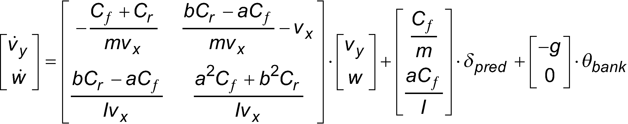
Vorausschauendes Fahrzeuggeschwindigkeitsregelungssystem, umfassend:einen Fahrzeuggeschwindigkeitsprofilgenerator, der ausgestaltet ist, um ein Geschwindigkeitsprofil gemäß einer vorhergesagten Querbeschleunigung einer Zielkurve (24), die zumindest teilweise aus Kartendaten (19) identifiziert wird, zu erzeugen; undeinen Geschwindigkeitscontroller (8), der ausgestaltet ist, um eine Fahrzeuggeschwindigkeitsverringerung gemäß dem Geschwindigkeitsprofil zu starten,wobei die vorhergesagte Querbeschleunigung berechnet wird gemäß[v˙yw˙]=[−Cƒ+CrmvxbCr−aCƒmvx−vxbCr−aCƒIvxa2Cƒ+b2CrIvx]⋅[vyw]+[CƒmaCƒI]⋅δpred+[−g0]⋅θbankwobei v̇ydie vorhergesagte Querbeschleunigung ist, δpredder vorhergesagte Lenkwinkel ist, m die Fahrzeugmasse ist, I die Fahrzeugträgheit ist, Cfund Crdie vordere bzw. hintere Kurvensteifigkeit des Fahrzeugs (5) sind, vxdie Fahrzeuglängsgeschwindigkeit (37) ist, a und b Distanzen zwischen einem Fahrzeugschwerpunkt und einer Vorder- bzw. Hinterachse sind, v̇ydie Fahrzeugquergeschwindigkeit (33) ist, w die Gierrate (31) ist, w die zeitliche Ableitung der Gierrate (31) ist, g die Erdbeschleunigungskonstante ist und θbankein Querneigungswinkel relativ zur Horizontalen ist.A predictive vehicle speed control system comprising:a vehicle speed profile generator configured to generate a speed profile according to a predicted lateral acceleration of a target curve (24) identified at least in part from map data (19); anda speed controller (8) configured to start a vehicle speed reduction according to the speed profile,wherein the predicted lateral acceleration is calculated according to [v˙yw˙]=[−Cƒ+CrmvxbCr−aCƒmvx−vxbCr−aCƒIvxa2Cƒ+b2CrIvx]⋅[vyw ]+[CƒmaCƒI]⋅δpred+[−g0]⋅θbankwhere v̇y is the predicted lateral acceleration, δpred is the predicted steering angle, m is the vehicle mass, I is the vehicle inertia, Cfund Crare the front and rear cornering stiffness of the vehicle (5), vxis the vehicle longitudinal velocity ( 37), a and b are distances between a vehicle center of gravity and a front or rear axle, v̇y is the vehicle lateral velocity (33), w is the yaw rate (31), w is the time derivative of the yaw rate (31), g is the gravitational acceleration constant and θb is a bank angle relative to horizontal.
Description
HINTERGRUNDBACKGROUND
Die vorliegende Erfindung bezieht sich allgemein auf eine vorausschauende Geschwindigkeitsplanung für eine Fahrzeuggeschwindigkeitsregelung, und bezieht sich im Speziellen auf eine Echtzeit-Geschwindigkeitsprofilerzeugung in Ansprechen auf sich ändernde Straßenattribute.The present invention relates generally to predictive speed planning for vehicle cruise control, and more particularly relates to real-time speed profiling in response to changing road attributes.
ZUSAMMENFASSUNGSUMMARY
Aufgabe der Erfindung ist es, ein verbessertes vorausschauendes Fahrzeuggeschwindigkeitsregelungssystem und ein verbessertes Verfahren zur vorausschauenden Geschwindigkeitsregelung bereitzustellen.It is an object of the invention to provide an improved predictive vehicle cruise control system and method for predictive cruise control.
Zur Lösung der Aufgabe sind ein vorausschauendes Fahrzeuggeschwindigkeitsregelungssystem mit den Merkmalen des Anspruchs 1 und ein Verfahren zur vorausschauenden Geschwindigkeitsregelung mit den Merkmalen des Anspruchs 10 vorgesehen. Vorteilhafte Ausbildungen der Erfindung sind den Unteransprüchen, der Beschreibung und den Zeichnungen zu entnehmen.To achieve the object, a predictive vehicle cruise control system having the features of
Figurenlistecharacter list
Der als die Erfindung betrachtete Gegenstand wird in dem abschließenden Teil der Beschreibung speziell hervorgehoben und deutlich beansprucht. Die Merkmale und deren Interaktion, Betrieb und Vorteile werden am besten angesichts der folgenden detaillierten Beschreibung und der Zeichnungen verstanden, in denen:
-
1 eine schematische, perspektivische Ansicht eines Fahrzeugs, das mit einer vorausschauenden Geschwindigkeitsregelung ausgestattet ist, gemäß einem Beispiel ist; -
2 ein schematisches Blockdiagramm des vorausschauenden Geschwindigkeitsregelungssystems gemäß einem Beispiel ist; -
3 eine schematische Draufsicht des Fahrzeugs von1 während einer automatischen Geschwindigkeitsverringerung in Erwartung einer elektronisch detektierten bevorstehenden Kurve gemäß einem Beispiel ist; -
4 ein Vektordiagramm des Fahrzeugs von1 , das die Kurve von3 passiert, gemäß einem Beispiel ist; und -
5 ein Flussdiagramm, das die Betriebsschritte zeigt, die an der vorausschauenden Geschwindigkeitsregelung beteiligt sind, gemäß einem Beispiel ist.
-
1 12 is a schematic perspective view of a vehicle equipped with predictive cruise control, according to an example; -
2 Figure 12 is a schematic block diagram of the predictive cruise control system according to an example; -
3 a schematic top view of the vehicle of FIG1 is during an automatic deceleration in anticipation of an electronically detected upcoming curve, according to one example; -
4 a vector diagram of the vehicle from1 , which the curve of3 happened, according to an example is; and -
5 Figure 12 is a flow chart showing the operational steps involved in predictive cruise control, according to one example.
Es sei angemerkt, dass aus Gründen der Klarheit Figurenelemente nicht maßstabgetreu dargestellt sein müssen und analoge Elemente identische Bezugszeichen teilen können.It should be noted that for the sake of clarity figure elements need not be drawn to scale and analogous elements may share identical reference numbers.
DETAILLIERTE BESCHREIBUNGDETAILED DESCRIPTION
Die folgende Beschreibung umfasst Details, die notwendig sind, um ein gründliches Verständnis der Erfindung bereitzustellen, und es sei angemerkt, dass die Beispiele ohne diese spezifischen Details ausgeführt werden können. Ferner wurden weithin bekannte Verfahren, Prozeduren und Komponenten weggelassen, um Merkmale der Beispiele hervorzuheben.The following description includes details necessary to provide a thorough understanding of the invention, and it should be noted that the examples may be practiced without these specific details. Furthermore, well-known methods, procedures, and components have been omitted to emphasize features of the examples.
Das vorliegende Beispiel bezieht sich allgemein auf eine vorausschauende Geschwindigkeitsregelung für eine Fahrzeuggeschwindigkeitsregelung, und bezieht sich im Speziellen auf eine Echtzeit-Geschwindigkeitsprofilerzeugung, die auf sich ändernde Straßenattribute anspricht wie oben erwähnt.The present example relates generally to predictive cruise control for vehicle cruise control, and more particularly relates to real-time speed profiling responsive to changing road attributes as noted above.
Die folgenden Begriffe werden in der gesamten Druckschrift verwendet.The following terms are used throughout this publication.
„Straßenattribute“ beziehen sich auf straßenbezogene Eigenschaften wie unter anderem Krümmung, Neigung und Querneigungswinkel.“Road Attributes” refer to road-related properties such as, but not limited to, curvature, grade, and bank angle.
„Fahrzeugparameter“ beziehen sich auf fahrzeugbezogene Eigenschaften wie unter anderem Fahrzeugmasse, Fahrzeugträgheit, Distanz, die sich von dem Schwerpunkt zu jeder Achse erstreckt, sowie vordere und hintere Kurvensteifigkeit.“Vehicle parameters” refer to vehicle-related characteristics such as, but not limited to, vehicle mass, vehicle inertia, distance extending from the center of gravity to each axis, and front and rear cornering stiffness.
„Dynamische Fahrzeugvariablen“ beziehen sich auf sich ändernde Zustandsvariablen wie unter anderem Fahrzeugort, Längs- und Quergeschwindigkeit, Längs- und Querbeschleunigung, Lenkwinkel, Änderung des Lenkwinkels und Winkelfahrtrichtung."Dynamic vehicle variables" refer to changing state variables such as, but not limited to, vehicle location, longitudinal and lateral speed, longitudinal and lateral acceleration, steering angle, change in steering angle, and angular travel direction.
„Kurve" bezieht sich gemäß einem Beispiel auf einen Satz von Punkten, die einen im Wesentlichen identischen Krümmungsradius in einem Straßensegment aufweisen."Curve" refers to a set of points that have a substantially identical radius of curvature in a road segment, according to one example.
Nun auf
Im Allgemeinen umfasst das vorausschauende Geschwindigkeitsregelungssystem 1 gemäß einem Beispiel einen Geschwindigkeitsprofilgenerator 12, der ausgestaltet ist, um Kartendaten in Verbindung mit Kamera- und Objektsensordaten zu verarbeiten, um ein Geschwindigkeitsprofil zu erzeugen, eine Ortsverfolgungseinheit 2, die ausgestaltet ist, um einen Fahrzeugort zu identifizieren, und einen Geschwindigkeitscontroller 8, der ausgestaltet ist, um Änderungen der Geschwindigkeit gemäß dem Geschwindigkeitsprofil über eine Kopplung mit dem Fahrzeugmotor zu realisieren oder zu initiieren.In general, according to one example, the predictive
Im Speziellen umfasst der Geschwindigkeitsprofilgenerator 12 gemäß einem Beispiel einen oder mehrere Prozessoren oder Controller 14, einen Speicher 15, einen nicht transitorischen Langzeitspeicher 16, der eine Datenbank mit Kartendaten 19 enthält, einen Objektdetektionssensor 13, eine nach vorn gerichtete Kamera 11, eine Mensch-Maschine-Schnittstelle (HMI von Human Machine Interface) 7 mit sowohl Eingabeeinrichtungen 17 als auch Ausgabeeinrichtungen 18.Specifically,
Der Prozessor 14 kann beispielsweise als zentrale Verarbeitungseinheit (CPU von central processing unit), als Mikrochip oder als Recheneinrichtung mit analoger Funktionalität realisiert sein; welche alle ausgestaltet sind, um Code oder Anweisungen, die in dem Speicher 15 oder Langzeitspeicher 16 gespeichert sind, auszuführen.The
Der Speicher 15 kann als Direktzugriffsspeicher (RAM von Random Access Memory), Nur-Lese-Speicher (ROM von read only memory), dynamischer RAM (DRAM von Dynamic RAM), synchroner DRAM (SD-RAM von Synchronous DRAM), Speicherchip mit doppelter Datenrate (DDR von double data rate), Flash- oder nicht flüchtiger Speicher, flüchtiger Speicher, Cache- oder Pufferspeicher oder andere geeignete Speichereinheiten oder Speicherungseinheiten realisiert sein.The
Der nicht transitorische Langzeitspeicher 16 kann zum Beispiel als Festplattenlaufwerk, als Diskettenlaufwerk, als Compact Disk-Laufwerk (CD-Laufwerk), als CD-Recordable-Laufwerk (CD-R-Laufwerk), als Flash-Speichereinrichtung realisiert sein. Es sei angemerkt, dass auch verschiedene Kombinationen der obigen Speicher- und Speicherungseinrichtungen im Schutzumfang der vorliegenden Erfindung umfasst sind, und dass Bilddaten, Code und andere relevante Datenstrukturen in den oben angegebenen Speicher- und/oder Speicherungseinrichtungen gespeichert sind.The non-transitory long-
Die nach vorn gewandte Kamera oder die nach vorn gewandten Kameras 11 sind ausgestaltet, um eine Information einer bevorstehenden Straßengeometrie zu erfassen, entweder als mehrere Standbilder oder als Video oder als Kombination von beidem. Bei einem bestimmten Beispiel werden Kameradaten mit Kartendaten 19 oder GPS-Daten oder beidem vereinigt, wenn schlechte Wetterbedingungen die Zuverlässigkeit der Kameradaten und Sensordaten von dem Objektsensor 13 verringern wie oben erwähnt. Wie es Fachleuten bekannt ist, können verschiedene Datenvereinigungstechniken eingesetzt werden. Ein solches Beispiel ist in der Patentanmeldungsveröffentlichung US 2012 / 0 290 146 A1 beschrieben, deren Offenbarungsgehalt hierin durch Bezugnahme vollständig mit eingeschlossen ist. Die nach vorn gerichtete Kamera 11 kann gemäß einem Beispiel zur Erweiterung solcher Kartendatenunzulänglichkeiten bis zu einem Bereich [engl.: „rage“] von etwa 120 Metern wirksam sein.The forward-facing camera or
Ein einzelner Objektdetektionssensor oder eine Vielzahl von derartigen Sensoren 13 ist oder sind ausgestaltet, um Fahrzeuge und ein Objekt vor dem Fahrzeug 5 zu detektieren, und können unter anderem als Radar, Light Detection and Ranging (LIDAR), inertiale Messeinheit (IMU von Inertial Measurement Unit) oder verschiedene Kombinationen davon realisiert sein. Gemäß einem Beispiel können Vorwärtskameradaten mit Objektsensordaten für eine verbesserte Genauigkeit bei der Objektdetektion vereinigt werden. Ferner können IMU-Daten kombiniert mit Daten einer relativen Bewegung durch den Objektdetektionssensor 13 bereitgestellt werden, um Daten einer absoluten Bewegung eines Objekts zu erhalten.A single object detection sensor or a plurality of
Die Eingabeeinrichtungen 17 umfassen unter anderem Mikrofone, Touchscreens, Tastenfelder, Videokameras, und die Ausgabeeinrichtungen 18 umfassen unter anderem einen Monitor, Leuchten, Lautsprecher und haptische Einrichtungen und verschiedene Kombinationen davon.The
Gemäß einem Beispiel ist die Ortsverfolgungseinheit 2 ausgestaltet, um den Fahrzeugort entweder basierend auf von dem GPS-Empfänger 9 erhaltenen GPS-Daten oder einer Koppelnavigation, die Geschwindigkeits- und Kilometerleistungsdaten von dem Geschwindigkeitsmesser 3 und dem Entfernungsmesser 4 einsetzt, zu verfolgen.According to one example, the
Es sind ein vorläufiger Fahrpfad 29, der der aus den Kartendaten identifizierten Spurmitte zugehörig ist, und die identifizierte maximale Krümmung bei Punkt 24 gezeigt. Die nach vorn gewandte Kamera 11 (gezeigt in
Der am Fahrzeug zentrierte Fahrpfad 27 wird durch Lenkkrümmungen δt1 - δt5 gemäß dem Objektsensor und Kameradaten, die verwendet werden, um den Fahrpfad 29 zu modifizieren, definiert, wie es weiter erläutert wird.The vehicle-
Bei einem bestimmten Beispiel werden Straßenattribute bevorstehender Straßensegmente in einer Distanz im Bereich zwischen 200 m und 400 m im Voraus überprüft, gemäß einem Beispiel für Geschwindigkeiten bis zu etwa 145 km/h bzw. 90 mph.In a specific example, road attributes of upcoming road segments are pre-checked at a distance ranging between 200 m and 400 m, according to an example for speeds up to about 145 km/h or 90 mph.
Gezeigt sind gemäß einem Beispiel ein vorderer und ein hinterer Reifen 30, die mit Längsdistanzen „a“ bzw. „b“ von dem Schwerpunkt 32 des Fahrzeugs, einer seitlichen Distanz „y“ 35 von der Spurmitte 29, einem Fahrzeugfahrtrichtungswinkel „φ“ 36, einer Fahrzeugquergeschwindigkeit „vy“ 33, einer Fahrzeuglängsgeschwindigkeit „vx“ 37, einer Gierrate „w“ 31 und einem Lenkwinkel „δ“ 34 angeordnet sind.According to an example, a front and a
In Verarbeitungsschritt 41 tastet die vorausschauende Geschwindigkeitsregelung 12 während der Fahrt eine Kartendatenbank 19 ab und identifiziert eine bevorstehende Ziel- oder Destinationskurve mit dem größten Krümmungsradius unter den Krümmungsradien 23, 24 und 25 wie oben erwähnt. Alternativ kann die maximale Krümmung 24 von der nach vorn gewandten Kamera 11 oder Straßenprofildaten, die durch den GPS-Empfänger 9 empfangen werden, und dem Objektsensor 13 oder einer Kombination aus diesen identifiziert werden, wie es dem Fachmann bekannt ist.In processing
Geeignete Kartendaten sind bei NAVTEQ Corporation; 425 West Randolph Street; Chicago, Illinois 60606 USA; und online unter http://corporate.navteq.com/products_data_whatis.htm erhältlich. Zusätzliche Kartenanbieter umfassen Google Map, Microsoft Map, Open Street Map, Garmin und Magellan.Appropriate map data is available from NAVTEQ Corporation; 425 West Randolph Street; Chicago, Illinois 60606 USA; and available online at http://corporate.navteq.com/products_data_whatis.htm. Additional map providers include Google Map, Microsoft Map, Open Street Map, Garmin and Magellan.
In Schritt 42 wird der an der Spur zentrierte Fahrpfad 29 auf der Grundlage der identifizierten Zielkurve 24 identifiziert.In
In Verarbeitungsschritt 43 wird unter Verwendung von Daten, die von der nach vorn gewandten Kamera 11 geliefert werden, ein außermittiger am Fahrzeug zentrierter Fahrpfad (VCP von Vehicle-Centered Travel Path) 27 identifiziert. Das System 1 ist ausgestaltet, um anzunehmen, dass ein Fahrer die Fahrt auf dem an der Spur zentrierten Fahrpfad 29 gemäß der folgenden Pfadgleichung lenkt:![]()
![]()
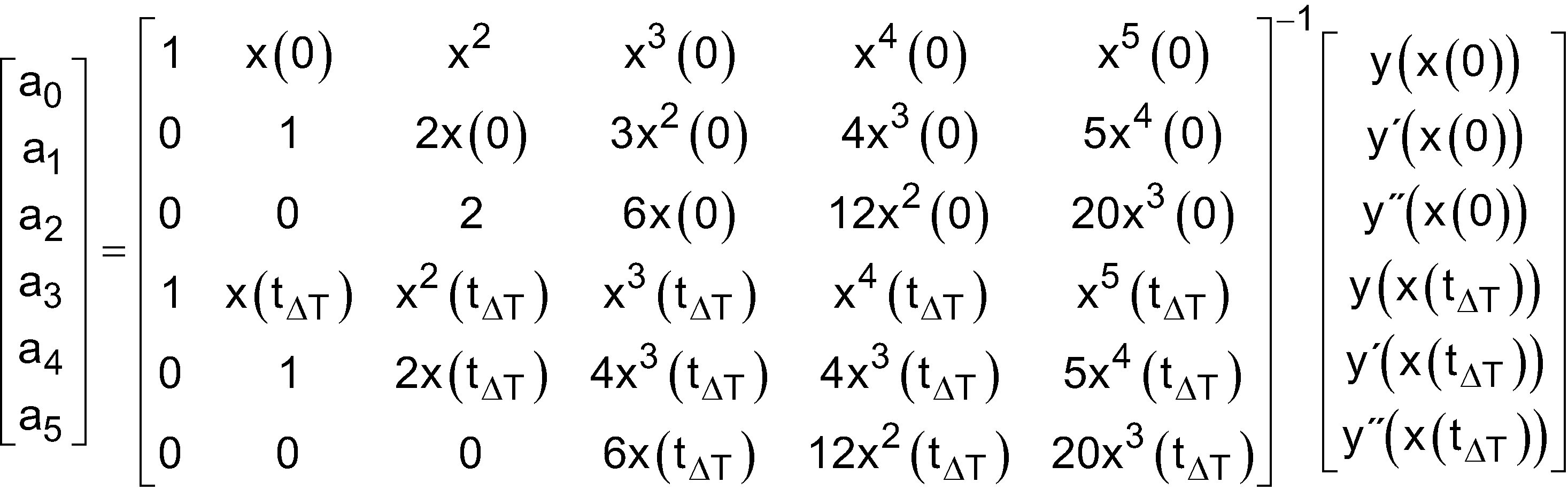
![]()
![]()
In Verarbeitungsschritt 44 werden vorhergesagte Fahrzeugbewegungsvariablen vx, vy, w, ay und w aus der oben erwähnten Pfadgleichung berechnet.In
In der ersten Iteration überprüft das System 1 den aktuellen Geschwindigkeitsmesserwert hinsichtlich einer Konformität mit Sicherheits- und Komfortmetrikbeschränkungen, und wenn keine Konformität vorliegt, berechnet es iterativ vorgeschlagene reduzierte Geschwindigkeiten, bis eine konforme Geschwindigkeit gefunden wird.In the first iteration, the
Wie erwähnt wird vx zuerst als Geschwindigkeit mit konstantem Wert während der gesamten Fahrtzeit zur Zielkurve, die von einem Geschwindigkeitsmesser zerlegt wird, angenommen. Entsprechende Fahrzeugbewegungsvariablen werden gemäß Folgendem berechnet:![]()
![]()
![]()
![]()
![]()
![]()
![]()
![]()
![]()
![]()
![]()
![]()
In Verarbeitungsschritt 45 werden der vorhergesagte Lenkwinkel „δpred“ und ein entsprechender Änderungslenkwinkel „Δδ“ aus den Werten der Fahrzeugbewegungsvariablen vx, vy, w, ay und w berechnet, die für das vorherige Zeitintervall ermittelt wurden, gemäß:
- Wobei „g“ die Erdbeschleunigungskonstante ist.
- „θbank“ ein Querneigungswinkel relativ zur Horizontalen ist.
- „I“ die Fahrzeugträgheit ist und ein bekannter Fahrzeugparameter ist.
- „m“ die Fahrzeugmasse ist und ein bekannter Fahrzeugparameter ist.
- „a“ und „b“ Distanzen zwischen dem Fahrzeugschwerpunkt und der Vorder- bzw. Hinterachse sind und bekannte Fahrzeugparameter sind.
- „Cf“ und „Cr“ Faktoren einer vorderen und hinteren Kurvensteifigkeit sind und bekannte Fahrzeugparameter sind.
- Where "g" is the gravitational acceleration constant.
- "θ bank " is a bank angle relative to horizontal.
- "I" is the vehicle inertia and is a known vehicle parameter.
- "m" is the vehicle mass and is a known vehicle parameter.
- "a" and "b" are distances between the vehicle's center of gravity and the front and rear axles, respectively, and are known vehicle parameters.
- "Cf" and "C r " are factors of front and rear cornering stiffness and are known vehicle parameters.
Der Änderungslenkwinkel „Δδ“ ist gemäß einer Ausführungsform für jeden vorhergesagten Lenkwinkel „δpred“ jeweils einfach die Differenz zwischen dem vorhergesagten Lenkwinkel und seinem vorherigen Wert bei dem vorherigen Zeitinkrement.For each predicted steering angle "δ pred ", the change steering angle "Δδ" is simply the difference between the predicted steering angle and its previous value at the previous time increment, according to one embodiment.
In dem Verarbeitungsschritt 46 wird die Querbeschleunigung „ay, predicted“ gemäß der in Absatz [044] dargelegten obigen Bewegungsgleichung berechnet.In
Wie erwähnt werden diese Berechnungen gemäß einem Beispiel während der gesamten berechneten Fahrtzeit zur Zielkurve 24 in Zeitinkrementen von 0,1 Sekunden-Schritten ständig wiederholt. Es sei angemerkt, dass auch andere Zeitinkremente, die die notwendige Systemfunktionalität bereitstellen, eingesetzt werden können. Die Fahrtzeit zur Zielkurve 24 wird aus Distanzdaten ermittelt oder von der Datenkarte in Verbindung mit dem Geschwindigkeitsmesser oder von GPS-Geschwindigkeitsdaten oder einer Kombination aus diesen empfangen.As mentioned, according to one example, these calculations are continuously repeated in time increments of 0.1 second steps throughout the calculated travel time to the
In Verarbeitungsschritt 47 wird der vorhergesagte Lenkwinkel δpred mit der Sicherheitsbeschränkung δlimit verglichen, und wenn der Vergleich angibt, dass die vorhergesagte Lenkkurve δpred geringer ist als die Sicherheitsbeschränkung, fährt die Verarbeitung mit Schritt 48 fort. Die Lenkwinkelbeschränkung ist ein geschwindigkeitsabhängiger Wert, der sich für jedes Fahrzeug unterscheidet, und wird gemäß einem Beispiel aus einer Nachschlagetabelle erhalten.In
In Verarbeitungsschritt 48 wird die vorhergesagte Änderung Δδpred des Lenkwinkels mit der Sicherheitsbeschränkung Δδlimit verglichen, und wenn der Vergleich angibt, dass die vorhergesagte Änderung Δδpred der Lenkkurve geringer ist als die Sicherheitsbeschränkung, fährt die Verarbeitung mit Schritt 49 fort. Die Sicherheitsbeschränkung Δδlimit ist gemäß einem Beispiel auch ein geschwindigkeitsabhängiger Wert, der sich für jedes Fahrzeug unterscheidet, und wird aus einer Nachschlagetabelle erhalten.In
Gemäß einem Beispiel wird in Verarbeitungsschritt 49 der Absolutwert der aktualisierten Querbeschleunigung ay, predicted mit der Sicherheitsbeschränkung ay,limit verglichen, und wenn der Vergleich angibt, dass die vorhergesagte Querbeschleunigung innerhalb der Sicherheitsbeschränkungen liegt, wird keine Korrekturmaßnahme durchgeführt, und das System 1 überwacht weiterhin die Straßenbedingungen.According to one example, in processing
Wenn jedoch einer der obigen Vergleiche in den Schritten 47, 48 und 49 angibt, dass entweder der vorhergesagte Lenkwinkel δpred oder die Änderung Δ5pred des Lenkwinkels oder die Querbeschleunigung ay, predicted seinen bzw. ihren jeweiligen Beschränkungswert übersteigt, fährt die Verarbeitung mit Schritt 50 fort, in dem jedem Parameter über seinen Schwellenwert hinaus sein jeweiliger Beschränkungswert zugeordnet wird und ein entsprechender Wert der horizontalen Geschwindigkeit vx an dem aktuellen Ort des Fahrzeugs gemäß der oben erwähnten Dynamikgleichung von Absatz [44] berechnet wird.However, if any of the above comparisons in
In Verarbeitungsschritt 50 erfolgt eine Bewertung in Bezug auf die in den Schritten 47 - 49 erfüllten Bedingungen bezüglich einer oder keiner reduzierten Geschwindigkeit. Wenn sie sich nicht auf eine reduzierte Geschwindigkeit beziehen, fährt die Verarbeitung mit Schritt 41 fort, in dem das System 1 das Abtasten von Kartendaten 19 und Kameradaten oder der Kombination dieser hinsichtlich bevorstehender Änderungen der Straßengeometrie fortsetzt. Wenn ermittelt wird, dass sich die in den Schritten 47 - 49 erfüllten Bedingungen auf eine reduzierte Geschwindigkeit beziehen, fährt die Verarbeitung mit Schritt 53 fort.In
In Verarbeitungsschritt 53 wird der Geschwindigkeitsverringerungsort 20B auf der Grundlage der vorgeschlagenen Geschwindigkeit, nun als Zielgeschwindigkeit „vdes_curve“ bezeichnet, und einer Längsbeschleunigungsbeschränkung „ax, lim“, die gemäß einem Beispiel in einem Bereich zwischen etwa 0,12 g ∼ 0,15 g liegt, identifiziert.In
Eine Geschwindigkeitsverringerungsdistanz „s dest_curve“, die sich von der Zielkurve 24 zu dem Geschwindigkeitsverringerungsort 20B erstreckt, wird aus der folgenden Gleichung erhalten:![]()
![]()
Wobei gemäß einem Beispiel „vcurve“ die Zielgeschwindigkeit in die Zielkurve 24 ist wie erwähnt, und „vx“ die aktuelle Längsgeschwindigkeit ist. Es sei angemerkt, dass nach „vx“ aus der vorgeschlagenen Geschwindigkeit aufgelöst werden kann, oder die vorgeschlagene Geschwindigkeit als eine Längsgeschwindigkeit realisiert sein kann.According to an example, “v curve ” is the target speed in the
System 1 initiiert die Geschwindigkeitsverringerung an Ort 20B mit einer Distanz von scurve von der engsten Zielkurve 24 mit einer Rate von „ax,lim“. Bei einem bestimmten Beispiel wird eine Geschwindigkeitsverringerungsrate kleiner als „ax,lim“ realisiert.
Ähnlich ist das System 1 auch ausgestaltet, um eine komfortable Geschwindigkeitsverringerung an einem identifizierten Geschwindigkeitsverringerungsort zu initiieren, wobei sichergestellt wird, dass die Fahrzeugfahrgeschwindigkeit mit einer bevorstehenden Geschwindigkeitsbeschränkungsänderung konform ist. Die Straßengeschwindigkeitsbeschränkung „vspd_limit“ wird aus der Kartendatenbank 19 erhalten, und die Distanz zur neuen Geschwindigkeitsbeschränkung „sdes_autoset“ wird berechnet gemäß:
Wenn sich das Fahrzeug 5 innerhalb der Distanz „sdes_autoset" zu einer neuen Geschwindigkeitsbeschränkung „vspd_limit“ befindet, initiiert das Geschwindigkeitsregelungssystem 1 eine Geschwindigkeitsverringerung mit einer Rate von „ax,lim“.When the
Die Fahrzeugortsdaten, die benötigt werden, um an dem Geschwindigkeitsverringerungsort 20B eine Geschwindigkeitsverringerung zu initiieren, werden von der Ortsverfolgungseinheit 2 erhalten.The vehicle location data required to initiate a speed reduction at the
In Schritt 54 bewertet die Ortsverfolgungseinheit 2, ob die verfügbaren GPS-Daten ausreichen, um den Geschwindigkeitsverringerungsort 20B in Bezug auf die aktuelle Position des Fahrzeugs 1 zu identifizieren. Wenn dies nicht der Fall ist, fährt die Verarbeitung mit Schritt 55 fort, in dem ein Koppelnavigationsalgorithmus eingesetzt wird, wie es weiter erläutert wird.In
Gemäß einem Beispiel informiert die HMI 7 des vorausschauenden Geschwindigkeitsregelungssystems 1 in Schritt 56 einen Fahrer hinsichtlich einer vorgeschlagenen Geschwindigkeitsverringerung, deren Beginn an dem Geschwindigkeitsverringerungsort 20B geplant ist, und fordert den Fahrer auf, anzugeben, dass er an der Aufhebung der geplanten Geschwindigkeitsverringerung interessiert ist. Die Form der Ausgabe und Eingabe wird durch eine beliebige oder eine Kombination von Modalitäten realisiert; visuell, akustisch und haptisch.According to one example, in
In Schritt 57wird ein Nichtvorhandensein einer Verwendungsreaktion als eine stillschweigende Zustimmung angenommen, und der Geschwindigkeitscontroller 8 fährt damit fort, die sicherheitsorientierte Geschwindigkeitsverringerung wie in Schritt 58 gezeigt zu initiieren. Wenn eine Fahrerrückmeldung empfangen wird, wird die geplante Geschwindigkeitsverringerung gemäß einem Beispiel wie in Schritt 59 gezeigt aufgehoben. Die Rückmeldung kann auch in einer beliebigen oder einer Kombination von Modalitäten bereitgestellt werden; gemäß den eingesetzten Eingabeeinrichtungen verbal, visuell oder taktil. Es sei angemerkt, dass innerhalb des Schutzumfangs der vorliegenden Erfindung auch Beispiele mit einer Geschwindigkeitsverringerung, die nur basierend auf einem Empfang einer Benutzerbestätigung realisiert wird, umfasst sind.In
Wie oben erwähnt setzt die Ortsverfolgungseinheit 8 gemäß einem Beispiel, wenn GPS-Daten nicht verfügbar oder unzureichend sind, eine Koppelnavigation ein, um aktuelle Ortsdaten zu erzeugen.As mentioned above, in one example, when GPS data is unavailable or insufficient,
Bei einem bestimmten Beispiel wird die Koppelnavigation in Verbindung mit einem Kalman-Filter realisiert, um die Genauigkeit und Zuverlässigkeit der Ortsdaten zu verbessern, um den Geschwindigkeitsverringerungsort 20A zu identifizieren.In one particular example, dead reckoning is implemented in conjunction with a Kalman filter to improve the accuracy and reliability of the location data to identify the
Der Koppelnavigationsalgorithmus verwendet Fahrzeugentfernungsmesser- und -geschwindigkeitsmesserzustandsdaten mit der letzten bekannten GPS-Fahrzeugposition gemäß den folgenden Zustandsgleichungen:The dead reckoning algorithm uses vehicle odometer and speedometer state data with the last known GPS vehicle position according to the following state equations:
Die zurückgelegte Distanz sm(k) stellt die zurückgelegte Distanz wie durch den Entfernungsmesser gemessen dar, und vm stellt die Geschwindigkeit wie durch den Geschwindigkeitsmesser gemessen dar.The distance traveled s m (k) represents the distance traveled as measured by the rangefinder and v m represents the speed as measured by the speedometer.
Der Längspositionsvektor ist gegeben durch:![]()
![]()
Der Querpositionsvektor ist gegeben durch:![]()
![]()
Wobei „k“ die Zeitvariable ist, sodass die Längsposition gegeben ist durch:
- x(k) = [s(k) ṡ(k)]T, und die Querposition gegeben ist durch:

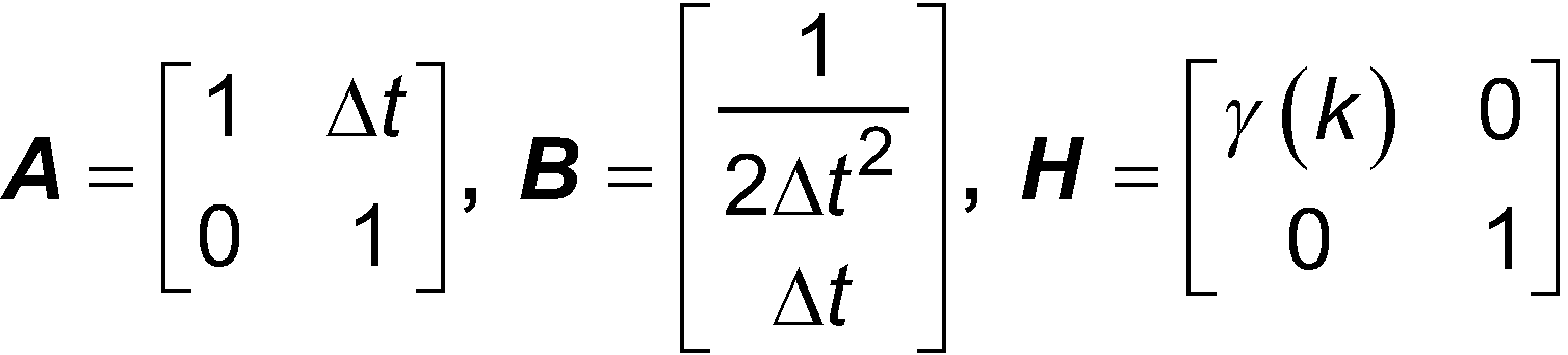
- • x(k) = [s(k) ṡ(k)]T wird über die Zeit als x̂-(k + 1) mit den folgenden Gleichungen vorhergesagt.
- • Aktualisierung der Kalman-Filterzeit (Vorhersage)


- • Aktualisierung der Kalman-Filtermessung (Korrektur)


- x(k) = [s(k) ṡ(k)] T , and the transverse position is given by:
- • x(k) = [s(k) ṡ(k)] T is predicted over time as x̂ - (k + 1) using the following equations.
- • Kalman filter time update (prediction)
- • Kalman filter measurement update (correction)
Der oben offenbarte Algorithmus beseitigt vorteilhaft eine erhebliche Offline-Berechnung und einen großen Speicher, die normalerweise für eine Tabellenspeicherung eines neuronalen Netzes oder eine Offline-Maschinenlernberechnung für eine Erzeugung einer Nachschlagetabelle erforderlich sind.The algorithm disclosed above advantageously eliminates significant off-line computation and large memory normally required for neural network table storage or off-line machine learning computation for look-up table generation.
Es sei angemerkt, dass nicht explizite Kombinationen von Merkmalen, die in verschiedenen Ausführungsformen dargelegt sind, auch innerhalb des Schutzumfangs der Erfindung umfasst sind.It should be noted that non-explicit combinations of features set forth in different embodiments are also included within the scope of the invention.
Während hierin bestimmte Merkmale der Erfindung veranschaulicht und beschrieben wurden, werden nun für den Fachmann viele Abwandlungen, Ersetzungen, Änderungen und Äquivalente ersichtlich werden. Es ist daher zu verstehen, dass die beigefügten Ansprüche alle solchen Abwandlungen und Änderungen abdecken sollen, da sie innerhalb des Gedankens der Erfindung liegen.While certain features of the invention have been illustrated and described herein, many modifications, substitutions, changes and equivalents will now become apparent to those skilled in the art. It is, therefore, to be understood that the appended claims are intended to cover all such modifications and changes as fall within the spirit of the invention.
Claims (15)

Applications Claiming Priority (2)
| Application Number | Priority Date | Filing Date | Title |
|---|---|---|---|
| US14/700,426 | 2015-04-30 | ||
| US14/700,426 US9650043B2 (en) | 2015-04-30 | 2015-04-30 | Real-time anticipatory speed control |
Publications (2)
| Publication Number | Publication Date |
|---|---|
| DE102016107938A1 DE102016107938A1 (en) | 2016-11-03 |
| DE102016107938B4 true DE102016107938B4 (en) | 2022-04-21 |
Family
ID=57135987
Family Applications (1)
| Application Number | Title | Priority Date | Filing Date |
|---|---|---|---|
| DE102016107938.3A Expired - Fee Related DE102016107938B4 (en) | 2015-04-30 | 2016-04-28 | PREDICTIVE VEHICLE CRUISE CONTROL SYSTEM AND PROCEDURES FOR PREDICTIVE CRUISE CONTROL |
Country Status (3)
| Country | Link |
|---|---|
| US (1) | US9650043B2 (en) |
| CN (1) | CN106080598B (en) |
| DE (1) | DE102016107938B4 (en) |
Families Citing this family (33)
| Publication number | Priority date | Publication date | Assignee | Title |
|---|---|---|---|---|
| JP6423212B2 (en) * | 2014-09-12 | 2018-11-14 | 株式会社ゼンリン | Driving support system, data structure |
| US10640111B1 (en) | 2016-09-07 | 2020-05-05 | Waymo Llc | Speed planning for autonomous vehicles |
| CN106891846A (en) * | 2016-12-30 | 2017-06-27 | 上海蔚来汽车有限公司 | Safety warning system and method based on Doppler effect |
| CN106740868B (en) * | 2016-12-30 | 2019-03-29 | 东软集团股份有限公司 | A kind of method, apparatus and equipment of speed planning |
| WO2018122586A1 (en) * | 2016-12-30 | 2018-07-05 | 同济大学 | Method of controlling automated driving speed based on comfort level |
| US10703359B2 (en) * | 2017-01-27 | 2020-07-07 | Ford Global Technologies, Llc | Controlling vehicle orientation |
| US10248129B2 (en) | 2017-04-19 | 2019-04-02 | GM Global Technology Operations LLC | Pitch compensation for autonomous vehicles |
| US10606273B2 (en) * | 2017-04-20 | 2020-03-31 | Baidu Usa Llc | System and method for trajectory re-planning of autonomous driving vehicles |
| JP6528336B2 (en) * | 2017-06-02 | 2019-06-12 | 本田技研工業株式会社 | Vehicle control system and vehicle control method |
| US10392001B2 (en) | 2017-08-11 | 2019-08-27 | Toyota Motor Engineering & Manufacturing North America, Inc. | Efficient acceleration semi-autonomous feature |
| KR102452551B1 (en) * | 2017-11-01 | 2022-10-07 | 현대자동차주식회사 | Apparatus for limiting lateral acceleration, system having the same and method thereof |
| US10627825B2 (en) | 2017-11-22 | 2020-04-21 | Waymo Llc | Using discomfort for speed planning in autonomous vehicles |
| US10967861B2 (en) | 2018-11-13 | 2021-04-06 | Waymo Llc | Using discomfort for speed planning in responding to tailgating vehicles for autonomous vehicles |
| DE102018210494B3 (en) * | 2018-06-27 | 2019-09-19 | Bayerische Motoren Werke Aktiengesellschaft | A method of operating a vehicle, computer readable medium, system, and vehicle |
| DE102018123147A1 (en) * | 2018-09-20 | 2020-03-26 | Schaeffler Technologies AG & Co. KG | Control device for a vehicle and vehicle with the control device and method for controlling the vehicle |
| GB2584587B (en) * | 2018-09-20 | 2023-01-04 | Jaguar Land Rover Ltd | Systems for Control of Understeer in an Autonomous Vehicle |
| JP2020050220A (en) * | 2018-09-28 | 2020-04-02 | ロベルト・ボッシュ・ゲゼルシャフト・ミト・ベシュレンクテル・ハフツングRobert Bosch Gmbh | Control device and control method |
| JP2020050221A (en) | 2018-09-28 | 2020-04-02 | ロベルト・ボッシュ・ゲゼルシャフト・ミト・ベシュレンクテル・ハフツングRobert Bosch Gmbh | Control device and control method |
| CN109189079B (en) * | 2018-11-05 | 2021-07-23 | 南京理工大学 | Navigation control method of mobile robot based on GPS positioning |
| CN111188900B (en) * | 2018-11-14 | 2021-09-17 | 北汽福田汽车股份有限公司 | Vehicle gear shifting monitoring method, device and system and vehicle |
| EP3929048A1 (en) * | 2018-11-15 | 2021-12-29 | Volvo Car Corporation | Vehicle safe stop |
| KR102592830B1 (en) * | 2018-12-05 | 2023-10-23 | 현대자동차주식회사 | Apparatus and method for predicting sensor fusion target in vehicle and vehicle including the same |
| JP7168910B2 (en) * | 2019-01-29 | 2022-11-10 | トヨタ自動車株式会社 | Vehicle travel control device |
| CN110281913A (en) * | 2019-06-24 | 2019-09-27 | 东莞市天佑运输服务有限公司 | A kind of anti-rollover method and system for haulage vehicle |
| JP7098580B2 (en) * | 2019-07-05 | 2022-07-11 | 株式会社東芝 | Predictors, predictors, programs and vehicle control systems |
| FR3098778B1 (en) * | 2019-07-16 | 2022-08-19 | Renault Sas | On-board driving aid method and device with outdated lane outline |
| DE102019218530B4 (en) * | 2019-11-29 | 2021-07-22 | Zf Friedrichshafen Ag | Method for determining a position of a motor vehicle |
| CN111284489B (en) * | 2020-03-24 | 2021-09-07 | 吉林大学 | Stochastic Predictive Cruise Control System for Intelligent Connected Vehicles |
| US12399496B2 (en) * | 2020-06-29 | 2025-08-26 | Lyft, Inc. | Detecting positioning of a sensor system associated with a vehicle |
| JP7298639B2 (en) * | 2021-03-26 | 2023-06-27 | いすゞ自動車株式会社 | Speed control auxiliary device |
| JP2023157128A (en) * | 2022-04-14 | 2023-10-26 | 西日本旅客鉄道株式会社 | Train sway determination system |
| US12485751B2 (en) | 2023-10-26 | 2025-12-02 | GM Global Technology Operations LLC | Methods and systems for using road preview to control vehicle velocity during cornering |
| US20250333070A1 (en) * | 2024-04-25 | 2025-10-30 | GM Global Technology Operations LLC | Optimization of vehicle performance to support vehicle control |
Citations (2)
| Publication number | Priority date | Publication date | Assignee | Title |
|---|---|---|---|---|
| DE102013216705A1 (en) | 2012-08-31 | 2014-03-06 | GM Global Technology Operations, LLC (n.d. Ges. d. Staates Delaware) | Forward-looking cruise control |
| DE102013221662A1 (en) | 2012-10-31 | 2014-04-30 | GM Global Technology Operations LLC (n. d. Gesetzen des Staates Delaware) | Systems and methods for controlling the speed of vehicles |
Family Cites Families (16)
| Publication number | Priority date | Publication date | Assignee | Title |
|---|---|---|---|---|
| EP1302356B1 (en) | 2001-10-15 | 2006-08-02 | Ford Global Technologies, LLC. | Method and system for controlling a vehicle |
| SE0104245D0 (en) | 2001-12-17 | 2001-12-17 | Scania Cv Abp | A method for a vehicle |
| US7260465B2 (en) | 2002-04-30 | 2007-08-21 | Ford Global Technology, Llc | Ramp identification in adaptive cruise control |
| US7124027B1 (en) * | 2002-07-11 | 2006-10-17 | Yazaki North America, Inc. | Vehicular collision avoidance system |
| US7512475B2 (en) | 2004-03-19 | 2009-03-31 | Delphi Technologies, Inc. | Automatic lateral acceleration limiting and non threat target rejection |
| SE529578C2 (en) | 2005-04-04 | 2007-09-25 | Scania Cv Abp | A method and system for controlling the operation of a vehicle |
| US7792624B2 (en) | 2005-10-05 | 2010-09-07 | Nissan Motor Co., Ltd. | Cruise control system |
| US7400963B2 (en) | 2005-12-09 | 2008-07-15 | Gm Global Technology Operations, Inc. | Speed control method for vehicle approaching and traveling on a curve |
| JP5056220B2 (en) | 2006-09-29 | 2012-10-24 | 日産自動車株式会社 | Travel control device |
| JP4265646B2 (en) | 2006-11-14 | 2009-05-20 | トヨタ自動車株式会社 | Cruise control control vehicle speed change device |
| US7774121B2 (en) * | 2007-07-31 | 2010-08-10 | Gm Global Technology Operations, Inc. | Curve speed control system with adaptive map preview time and driving mode selection |
| US9707974B2 (en) * | 2009-10-30 | 2017-07-18 | Ford Global Technologies, Llc | Vehicle with identification system |
| US8258934B2 (en) * | 2009-10-30 | 2012-09-04 | Ford Global Technologies, Llc | Vehicle and method of advising a driver therein |
| US8639426B2 (en) | 2010-07-15 | 2014-01-28 | George C Dedes | GPS/IMU/video/radar absolute/relative positioning communication/computation sensor platform for automotive safety applications |
| WO2012015403A1 (en) * | 2010-07-29 | 2012-02-02 | Ford Global Technologies, Llc | Systems and methods for scheduling driver interface tasks based on driver workload |
| US9393998B2 (en) * | 2013-12-04 | 2016-07-19 | Mobileye Vision Technologies Ltd. | Systems and methods for vehicle offset navigation |
-
2015
- 2015-04-30 US US14/700,426 patent/US9650043B2/en not_active Expired - Fee Related
-
2016
- 2016-04-28 DE DE102016107938.3A patent/DE102016107938B4/en not_active Expired - Fee Related
- 2016-05-03 CN CN201610282911.7A patent/CN106080598B/en active Active
Patent Citations (2)
| Publication number | Priority date | Publication date | Assignee | Title |
|---|---|---|---|---|
| DE102013216705A1 (en) | 2012-08-31 | 2014-03-06 | GM Global Technology Operations, LLC (n.d. Ges. d. Staates Delaware) | Forward-looking cruise control |
| DE102013221662A1 (en) | 2012-10-31 | 2014-04-30 | GM Global Technology Operations LLC (n. d. Gesetzen des Staates Delaware) | Systems and methods for controlling the speed of vehicles |
Also Published As
| Publication number | Publication date |
|---|---|
| CN106080598B (en) | 2019-06-25 |
| DE102016107938A1 (en) | 2016-11-03 |
| US9650043B2 (en) | 2017-05-16 |
| US20160318513A1 (en) | 2016-11-03 |
| CN106080598A (en) | 2016-11-09 |
Similar Documents
| Publication | Publication Date | Title |
|---|---|---|
| DE102016107938B4 (en) | PREDICTIVE VEHICLE CRUISE CONTROL SYSTEM AND PROCEDURES FOR PREDICTIVE CRUISE CONTROL | |
| DE102019133034B4 (en) | CONTROL OF AN AUTONOMOUS VEHICLE BASED ON A PREVIOUSLY LEARNED PASSENGER AND ENVIRONMENT-AWARE DRIVING STYLE PROFILE | |
| DE102018113927B4 (en) | System and method for lateral control of a vehicle at low speed | |
| DE102015111535B4 (en) | Algorithm for precise curvature estimation for the path planning of autonomous vehicles | |
| DE102015108605B4 (en) | Lane change path planning algorithm for an autonomous vehicle | |
| DE102012207525B4 (en) | System and method for improved detection of steering override during automatic lane centering | |
| DE102020113423A1 (en) | DEVICE AND METHOD FOR AUTONOMOUS DRIVING | |
| DE102019103352A1 (en) | TRAJECTOR PUBLIC TRACKING FOR VEHICLE PAGE CONTROL USING A NEURONAL NETWORK | |
| DE102011081159B4 (en) | Method and device for carrying out an evasive maneuver | |
| DE102017103972A1 (en) | Autonomous vehicle control taking into account a probability factor | |
| DE102017103971A1 (en) | Autonomous vehicle control with confidence factor | |
| DE102017103973A1 (en) | Autonomous vehicle control taking into account the driver's attention | |
| DE102017103969A1 (en) | Autonomous vehicle control with risk factor | |
| DE102018117916A1 (en) | Path planning for autonomous driving | |
| DE102017103970A1 (en) | Transition between autonomous vehicle control levels | |
| DE102011002275A1 (en) | Method for prognosis of driving behavior of preceding vehicle of motor vehicle i.e. motor car, involves prognosticating driving behavior based on characteristic values and travel route data of travel route lying ahead of preceding vehicle | |
| DE102016113903A1 (en) | Vehicle route determination | |
| DE102018116142A1 (en) | DEVICE FOR AUTONOMOUS DRIVING | |
| DE102012220146A1 (en) | Method for characterizing driving behavior of driver of e.g. motor car, involves obtaining accumulation information of trends over deviation time and providing accumulation information for characterizing driving behavior | |
| DE102022108677B3 (en) | Method, system and computer program product for determining objective parameters for predicting a subjective evaluation of a driver assistance system and/or an automated driver assistance function | |
| DE102021119285A1 (en) | DEVICE AND METHOD FOR CONTROLLING A VEHICLE | |
| DE102020103357A1 (en) | Computer readable medium containing vehicle control device, vehicle control method and program | |
| DE102023105222A1 (en) | DRIVE CONTROL DEVICE, A METHOD FOR DRIVE CONTROL AND A PROGRAM | |
| DE102018123896A1 (en) | Method for operating an at least partially automated vehicle | |
| DE102021110099A1 (en) | Path prediction for a vehicle |
Legal Events
| Date | Code | Title | Description |
|---|---|---|---|
| R012 | Request for examination validly filed | ||
| R016 | Response to examination communication | ||
| R018 | Grant decision by examination section/examining division | ||
| R020 | Patent grant now final | ||
| R119 | Application deemed withdrawn, or ip right lapsed, due to non-payment of renewal fee |