DE102015113985A1 - centrifugal pump - Google Patents
centrifugal pump Download PDFInfo
- Publication number
- DE102015113985A1 DE102015113985A1 DE102015113985.5A DE102015113985A DE102015113985A1 DE 102015113985 A1 DE102015113985 A1 DE 102015113985A1 DE 102015113985 A DE102015113985 A DE 102015113985A DE 102015113985 A1 DE102015113985 A1 DE 102015113985A1
- Authority
- DE
- Germany
- Prior art keywords
- impeller
- fluid
- centrifugal pump
- radially outer
- curved
- Prior art date
- Legal status (The legal status is an assumption and is not a legal conclusion. Google has not performed a legal analysis and makes no representation as to the accuracy of the status listed.)
- Withdrawn
Links
Images


Classifications
-
- F—MECHANICAL ENGINEERING; LIGHTING; HEATING; WEAPONS; BLASTING
- F04—POSITIVE - DISPLACEMENT MACHINES FOR LIQUIDS; PUMPS FOR LIQUIDS OR ELASTIC FLUIDS
- F04D—NON-POSITIVE-DISPLACEMENT PUMPS
- F04D17/00—Radial-flow pumps, e.g. centrifugal pumps; Helico-centrifugal pumps
- F04D17/08—Centrifugal pumps
- F04D17/10—Centrifugal pumps for compressing or evacuating
-
- F—MECHANICAL ENGINEERING; LIGHTING; HEATING; WEAPONS; BLASTING
- F04—POSITIVE - DISPLACEMENT MACHINES FOR LIQUIDS; PUMPS FOR LIQUIDS OR ELASTIC FLUIDS
- F04D—NON-POSITIVE-DISPLACEMENT PUMPS
- F04D29/00—Details, component parts, or accessories
- F04D29/18—Rotors
- F04D29/22—Rotors specially for centrifugal pumps
- F04D29/2238—Special flow patterns
- F04D29/2255—Special flow patterns flow-channels with a special cross-section contour, e.g. ejecting, throttling or diffusing effect
-
- F—MECHANICAL ENGINEERING; LIGHTING; HEATING; WEAPONS; BLASTING
- F04—POSITIVE - DISPLACEMENT MACHINES FOR LIQUIDS; PUMPS FOR LIQUIDS OR ELASTIC FLUIDS
- F04D—NON-POSITIVE-DISPLACEMENT PUMPS
- F04D29/00—Details, component parts, or accessories
- F04D29/18—Rotors
- F04D29/22—Rotors specially for centrifugal pumps
- F04D29/24—Vanes
- F04D29/242—Geometry, shape
-
- F—MECHANICAL ENGINEERING; LIGHTING; HEATING; WEAPONS; BLASTING
- F04—POSITIVE - DISPLACEMENT MACHINES FOR LIQUIDS; PUMPS FOR LIQUIDS OR ELASTIC FLUIDS
- F04D—NON-POSITIVE-DISPLACEMENT PUMPS
- F04D29/00—Details, component parts, or accessories
- F04D29/26—Rotors specially for elastic fluids
- F04D29/28—Rotors specially for elastic fluids for centrifugal or helico-centrifugal pumps for radial-flow or helico-centrifugal pumps
- F04D29/30—Vanes
Landscapes
- Engineering & Computer Science (AREA)
- Mechanical Engineering (AREA)
- General Engineering & Computer Science (AREA)
- Physics & Mathematics (AREA)
- Geometry (AREA)
- Structures Of Non-Positive Displacement Pumps (AREA)
Abstract
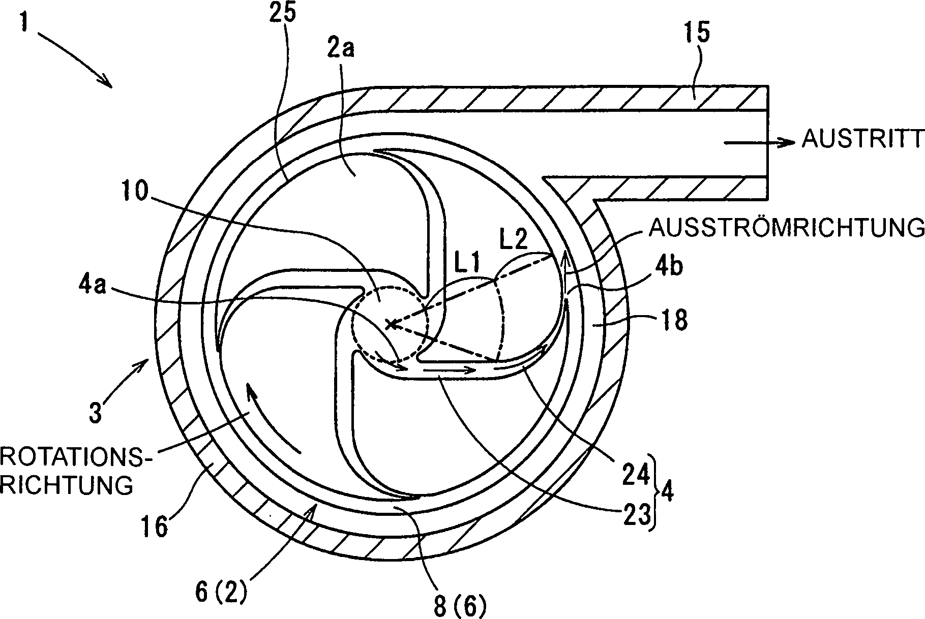
Eine Zentrifugalpumpe zum Beaufschlagen eines Fluids mit Druck durch Verwendung einer Zentrifugalkraft weist einen Impeller (2) und ein Gehäuse (3) auf. Der Impeller wird durch ein Stellglied drehbar betrieben. In dem Gehäuse ist der Impeller aufgenommen. Der Impeller weist Schaufeln (2a), die in einer Umfangsrichtung des Impellers hintereinander angeordnet sind, und eine Leitung (4) auf, die zwischen den nebeneinander in der Umfangsrichtung angeordneten Schaufeln definiert ist. Die Leitung weist einen linearen Bereich (23) und einen gekrümmten Bereich (24) auf. Der lineare Bereich erstreckt sich linear und weist einen gleichförmigen Querschnitt auf. Der gekrümmte Bereich (i) ist mit einem Ende des linearen Bereichs verbunden, (ii) erstreckt sich gekrümmt zu einer radial äußeren Seite des Impellers und (iii) nimmt im Querschnitt in Richtung auf die radial äußere Seite ab.A centrifugal pump for pressurizing a fluid by using a centrifugal force has an impeller (2) and a housing (3). The impeller is rotatably driven by an actuator. In the housing of the impeller is added. The impeller has vanes (2a) arranged one behind the other in a circumferential direction of the impeller and a duct (4) defined between the vanes arranged side by side in the circumferential direction. The conduit has a linear region (23) and a curved region (24). The linear region extends linearly and has a uniform cross-section. The curved portion (i) is connected to one end of the linear portion, (ii) extends curved toward a radially outer side of the impeller, and (iii) decreases in cross section toward the radially outer side.
Description
Die vorliegende Erfindung betrifft eine Zentrifugalpumpe zum Verdichten eines Fluids durch Verwendung der Zentrifugalkraft.The present invention relates to a centrifugal pump for compressing a fluid by using the centrifugal force.
Eine Zentrifugalpumpe weist herkömmlicherweise einen Impeller und ein Gehäuse auf. Ein Stellglied, wie z. B. ein Elektromotor, betreibt den Impeller in drehbarer Weise, und der Impeller ist in dem Gehäuse aufgenommen. Der Impeller weist Schaufeln auf, die in Umfangsrichtung hintereinander angeordnet sind, und die Schaufeln definieren eine Leitung zur Druckbeaufschlagung des Fluids. Insbesondere ist hinreichend bekannt, dass die Leitung in einer Zentrifugalpumpe mit einer niedrigen spezifischen Drehzahl in Richtung auf die äußere Umfangsseite spiralförmig gekrümmt ist, und dass ein Querschnitt der Leitung in Richtung auf die äußere Umfangsseite abnimmt (siehe z. B.
Das heißt, dass gemäß eine derartigen Zentrifugalpumpe das Fluid aus dem Impeller hausströmt, nachdem es durch die Leitung gelangt ist, während eine kinetische Energie des Fluids in eine Druckenergie umgewandelt wird. Dementsprechend kann die Zentrifugalpumpe vorzugsweise eine Konfiguration eines Typs einer niedrigen spezifischen Drehzahl aufweisen, da das Fluid mit einem geringeren Reibungsverlust mit Druck beaufschlagt werden kann.That is, according to such a centrifugal pump, the fluid flows from the impeller after it has passed through the conduit, while a kinetic energy of the fluid is converted into a pressure energy. Accordingly, the centrifugal pump may preferably have a configuration of a low specific speed type, since the fluid can be pressurized with less friction loss.
Da die Leitung gekrümmt ist, wird eine Leitungslänge von einem Einlass zu einem Auslass länger, und durch eine getrennte Strömung kann leicht eine Wirbelströmung verursacht werden. Durch die Wirbelströmung können Geräusche entstehen. Darüber hinaus geht heutzutage der Trend hin zur Energieeinsparung, und es besteht die Notwendigkeit, ein auf den Impeller ausgeübtes Drehmoment zu reduzieren und eine Drehzahl des Impeller zu erhöhen. Demzufolge kann es leicht zur Entstehung der getrennten Strömung und zur Entwicklung von Geräuschen kommen.Since the conduit is curved, a conduit length from an inlet to an outlet becomes longer, and a separate flow can easily cause turbulent flow. The vortex flow can cause noise. In addition, there is a trend toward energy saving today, and there is a need to reduce a torque applied to the impeller and to increase a speed of the impeller. As a result, the generation of separate flow and development of noise may easily occur.
Die vorliegende Offenbarung befasst sich mit der vorstehenden Problematik, und es ist eine Aufgabe der vorliegenden Offenbarung, eine Zentrifugalpumpe zu schaffen, mit der eine Unterdrückung von Geräuschen möglich ist.The present disclosure addresses the above problem, and it is an object of the present disclosure to provide a centrifugal pump capable of suppressing noise.
Eine Zentrifugalpumpe gemäß der vorliegenden Offenbarung dient zur Druckbeaufschlagung eines Fluids durch Verwendung einer Zentrifugalkraft. Die Zentrifugalpumpe weist einen Impeller und ein Gehäuse auf. Der Impeller wird in drehbarer Weise durch ein Stellglied betrieben. In dem Gehäuse ist der Impeller aufgenommen. Der Impeller weist Schaufeln auf, die in einer Umfangsrichtung des Impellers hintereinander angeordnet sind, und zwischen den nebeneinader in Umfangsrichtung befindlichen Schaufeln ist eine Leitung definiert. Die Leitung weist einen linearen Bereich und einen gekrümmten Bereich auf. Der lineare Bereich erstreckt sich linear und weist einen gleichförmigen Querschnitt auf. Der gekrümmte Bereich (i) ist mit einem Ende des linearen Bereichs verbunden, (ii) erstreckt sich gekrümmt zu einer radial äußeren Seite des Impellers und (iii) nimmt im Querschnitt in Richtung auf die radial äußere Seite ab.A centrifugal pump according to the present disclosure is for pressurizing a fluid by using a centrifugal force. The centrifugal pump has an impeller and a housing. The impeller is rotatably operated by an actuator. In the housing of the impeller is added. The impeller has vanes arranged one behind the other in a circumferential direction of the impeller, and a duct is defined between the adjacent vanes in the circumferential direction. The conduit has a linear region and a curved region. The linear region extends linearly and has a uniform cross-section. The curved portion (i) is connected to one end of the linear portion, (ii) extends curved toward a radially outer side of the impeller, and (iii) decreases in cross section toward the radially outer side.
Gemäß der Zentrifugalpumpe gemäß der vorliegenden Offenbarung kann, da die Leitung den linearen Bereich mit dem gleichförmigen Querschnitt aufweist, eine Leitungslänge der Leitung gekürzt werden, und eine Fläche, in der durch eine getrennte Strömung leicht eine Wirbelströmung entstehen kann, kann reduziert werden.According to the centrifugal pump according to the present disclosure, since the conduit has the linear portion with the uniform cross section, a conduit length of the conduit can be shortened, and a surface in which turbulent flow can easily be generated by a separate flow can be reduced.
Da der lineare Bereich zudem mit dem gekrümmten Bereich verbunden ist, der im Querschnitt in Richtung auf die radial äußere Seite abnimmt, kann die kinetische Energie des Fluids zuverlässig in Druckenergie umgewandelt werden. Demzufolge können in der Zentrifugalpumpe, und insbesondere in einer Zentrifugalpumpe mit einer niedrigen spezifischen Drehzahl, Geräusche unterdrückt werden.In addition, since the linear portion is connected to the curved portion decreasing in cross section toward the radially outer side, the kinetic energy of the fluid can be reliably converted into pressure energy. As a result, noises can be suppressed in the centrifugal pump, and particularly in a centrifugal pump having a low specific speed.
Die vorstehenden und weiteren Aspekte, Merkmale und Vorteile der vorliegenden Offenbarung werden anhand der nachstehenden ausführlichen Beschreibung unter Bezugnahme auf die beigefügte Zeichnung näher erläutert. Es zeigen:The foregoing and other aspects, features, and advantages of the present disclosure will become more apparent from the following detailed description made with reference to the accompanying drawings. Show it:
(Ausführungsform) (Embodiment)
Nachstehend wird eine Ausführungsform gemäß der vorliegenden Offenbarung erläutert. Es wird jedoch darauf hingewiesen, dass die Ausführungsform ein Beispiel für die vorliegende Offenbarung ist, und dass die vorliegende Offenbarung nicht auf die Ausführungsform beschränkt ist.Hereinafter, an embodiment according to the present disclosure will be explained. It is to be noted, however, that the embodiment is an example of the present disclosure, and that the present disclosure is not limited to the embodiment.
Eine Konfiguration einer Zentrifugalpumpe
Der Impeller
Der Impeller
Das Gehäuse
Der Einlassbereich
Die Ausgangswelle
Das Fluid, das in die Leitung
Es werden nun strukturelle Merkmale der Zentrifugalpumpe
Die Leitung
Der lineare Bereich
Der gekrümmte Bereich
Wenn ein Kreis
Eine projizierte Länge des linearen Bereichs
Wie vorstehend beschrieben, weist die Zentrifugalpumpe
Da die Leitung
Da zudem der lineare Bereich
Da der lineare Bereich
Außerdem ist eine Strömungsrichtung des Fluids, das aus der Leitung
(Eine weitere Modifikation)(Another modification)
Die vorliegende Offenbarung ist nicht auf die vorstehend beschriebene Ausführungsform beschränkt und kann gegebenenfalls modifiziert werden. Zum Beispiel weist die Zentrifugalpumpe
In der vorstehend beschriebenen Ausführungsform weist die Leitung
In der vorstehend beschriebenen Ausführungsform nimmt die Leitungsbreite des gekrümmten Bereichs
Es ist davon auszugehen, dass Veränderungen und Modifikationen in den Schutzbereich der vorliegenden Offenbarung fallen, der in den angehängten Ansprüchen definiert ist.It is to be understood that changes and modifications are within the scope of the present disclosure, which is defined in the appended claims.
ZITATE ENTHALTEN IN DER BESCHREIBUNG QUOTES INCLUDE IN THE DESCRIPTION
Diese Liste der vom Anmelder aufgeführten Dokumente wurde automatisiert erzeugt und ist ausschließlich zur besseren Information des Lesers aufgenommen. Die Liste ist nicht Bestandteil der deutschen Patent- bzw. Gebrauchsmusteranmeldung. Das DPMA übernimmt keinerlei Haftung für etwaige Fehler oder Auslassungen.This list of the documents listed by the applicant has been generated automatically and is included solely for the better information of the reader. The list is not part of the German patent or utility model application. The DPMA assumes no liability for any errors or omissions.
Zitierte PatentliteraturCited patent literature
- JP 2002-122095 A [0002] JP 2002-122095 A [0002]
- JP 2005-023794 A [0002] JP 2005-023794A [0002]
Claims (2)
Applications Claiming Priority (2)
| Application Number | Priority Date | Filing Date | Title |
|---|---|---|---|
| JP2014-230368 | 2014-11-13 | ||
| JP2014230368A JP6269447B2 (en) | 2014-11-13 | 2014-11-13 | Centrifugal pump |
Publications (1)
| Publication Number | Publication Date |
|---|---|
| DE102015113985A1 true DE102015113985A1 (en) | 2016-05-19 |
Family
ID=55855080
Family Applications (1)
| Application Number | Title | Priority Date | Filing Date |
|---|---|---|---|
| DE102015113985.5A Withdrawn DE102015113985A1 (en) | 2014-11-13 | 2015-08-24 | centrifugal pump |
Country Status (3)
| Country | Link |
|---|---|
| US (1) | US9938979B2 (en) |
| JP (1) | JP6269447B2 (en) |
| DE (1) | DE102015113985A1 (en) |
Families Citing this family (1)
| Publication number | Priority date | Publication date | Assignee | Title |
|---|---|---|---|---|
| JP5143317B1 (en) * | 2012-04-06 | 2013-02-13 | 三菱電機株式会社 | Air conditioner indoor unit |
Citations (2)
| Publication number | Priority date | Publication date | Assignee | Title |
|---|---|---|---|---|
| JP2002122095A (en) | 2000-10-17 | 2002-04-26 | Ebara Corp | Centrifugal pump |
| JP2005023794A (en) | 2003-06-30 | 2005-01-27 | Ebara Corp | Impeller |
Family Cites Families (7)
| Publication number | Priority date | Publication date | Assignee | Title |
|---|---|---|---|---|
| US3788765A (en) * | 1971-11-18 | 1974-01-29 | Laval Turbine | Low specific speed compressor |
| US4253798A (en) * | 1978-08-08 | 1981-03-03 | Eiichi Sugiura | Centrifugal pump |
| US5290236A (en) * | 1991-09-25 | 1994-03-01 | Baxter International Inc. | Low priming volume centrifugal blood pump |
| JPH09313600A (en) * | 1996-05-28 | 1997-12-09 | Terumo Corp | Centrifugal liquid pump |
| JP2003090298A (en) * | 2001-09-17 | 2003-03-28 | Nippon Soken Inc | Centrifugal fan |
| JP2004278311A (en) * | 2003-03-12 | 2004-10-07 | Ebara Corp | Centrifugal pump |
| JP2007239674A (en) | 2006-03-10 | 2007-09-20 | Ebara Corp | Impeller and centrifugal pump |
-
2014
- 2014-11-13 JP JP2014230368A patent/JP6269447B2/en not_active Expired - Fee Related
-
2015
- 2015-08-20 US US14/830,960 patent/US9938979B2/en not_active Expired - Fee Related
- 2015-08-24 DE DE102015113985.5A patent/DE102015113985A1/en not_active Withdrawn
Patent Citations (2)
| Publication number | Priority date | Publication date | Assignee | Title |
|---|---|---|---|---|
| JP2002122095A (en) | 2000-10-17 | 2002-04-26 | Ebara Corp | Centrifugal pump |
| JP2005023794A (en) | 2003-06-30 | 2005-01-27 | Ebara Corp | Impeller |
Also Published As
| Publication number | Publication date |
|---|---|
| JP2016094856A (en) | 2016-05-26 |
| US9938979B2 (en) | 2018-04-10 |
| US20160138599A1 (en) | 2016-05-19 |
| JP6269447B2 (en) | 2018-01-31 |
Similar Documents
| Publication | Publication Date | Title |
|---|---|---|
| EP3408503B1 (en) | Turbomachinery with bladed diffuser | |
| DE102012000376A1 (en) | Axial or diagonal fan | |
| DE102013114609A1 (en) | Radial impeller for a drum fan and fan unit with such a radial impeller | |
| EP3404269B1 (en) | Blower arrangement with flow dividing nozzle | |
| DE102018128792A1 (en) | Compact diagonal fan with guide device | |
| EP3224483B1 (en) | Centrifugal pump with guiding device | |
| DE102014106440A1 (en) | Impeller, in particular for a side channel machine | |
| DE2421237A1 (en) | PUMP | |
| DE112009000712T5 (en) | Hood guide vanes of an engine cooling fan with open wings | |
| DE102018128791A1 (en) | Diagonal fan with guide device | |
| DE19722353A1 (en) | Centrifugal pump with an inlet guiding device | |
| DE102009006652A1 (en) | Side channel blower, in particular secondary air blower for an internal combustion engine | |
| DE202018106504U1 (en) | Compact diagonal fan with tracking device | |
| EP2348220A1 (en) | Immersion pump | |
| EP3256732B1 (en) | Impeller for a ventilator and ventilator | |
| DE102020201831A1 (en) | IMPELLER FOR RADIAL COMPRESSORS, RADIAL COMPRESSORS AND TURBOCHARGERS | |
| DE20317171U1 (en) | Blower housing has the outer wall fitted with radial vanes to create radial inlet ducts to increase the inlet air flow and reduce noise | |
| DE897616C (en) | Axial or conical flow blower or axial or conical flow pump for conveying gases or liquids with a positive degree of reaction | |
| DE102009043230A1 (en) | Radial compressor diffuser | |
| DE102015113985A1 (en) | centrifugal pump | |
| DE202018106503U1 (en) | Diagonal fan with tracking device | |
| DE102015006458A1 (en) | Guide vane for a diffuser of a centrifugal compressor | |
| DE202017105384U1 (en) | Radial blower wheel with asymmetrical disc | |
| DE102017213507A1 (en) | Impeller for wastewater pump | |
| DE20319741U1 (en) | Radial or diagonal fan for ventilation has shaped blades, twisted in three dimensions |
Legal Events
| Date | Code | Title | Description |
|---|---|---|---|
| R012 | Request for examination validly filed | ||
| R119 | Application deemed withdrawn, or ip right lapsed, due to non-payment of renewal fee |