DE102014201585A1 - Device for positioning an examination object, method for creating an image with an imaging system and imaging system - Google Patents
Device for positioning an examination object, method for creating an image with an imaging system and imaging system Download PDFInfo
- Publication number
- DE102014201585A1 DE102014201585A1 DE102014201585.5A DE102014201585A DE102014201585A1 DE 102014201585 A1 DE102014201585 A1 DE 102014201585A1 DE 102014201585 A DE102014201585 A DE 102014201585A DE 102014201585 A1 DE102014201585 A1 DE 102014201585A1
- Authority
- DE
- Germany
- Prior art keywords
- imaging system
- movement
- examination
- examination subject
- sensor
- Prior art date
- Legal status (The legal status is an assumption and is not a legal conclusion. Google has not performed a legal analysis and makes no representation as to the accuracy of the status listed.)
- Withdrawn
Links
Images


Classifications
-
- A—HUMAN NECESSITIES
- A61—MEDICAL OR VETERINARY SCIENCE; HYGIENE
- A61B—DIAGNOSIS; SURGERY; IDENTIFICATION
- A61B5/00—Measuring for diagnostic purposes; Identification of persons
- A61B5/70—Means for positioning the patient in relation to the detecting, measuring or recording means
- A61B5/704—Tables
-
- A—HUMAN NECESSITIES
- A61—MEDICAL OR VETERINARY SCIENCE; HYGIENE
- A61B—DIAGNOSIS; SURGERY; IDENTIFICATION
- A61B5/00—Measuring for diagnostic purposes; Identification of persons
- A61B5/0033—Features or image-related aspects of imaging apparatus, e.g. for MRI, optical tomography or impedance tomography apparatus; Arrangements of imaging apparatus in a room
- A61B5/0035—Features or image-related aspects of imaging apparatus, e.g. for MRI, optical tomography or impedance tomography apparatus; Arrangements of imaging apparatus in a room adapted for acquisition of images from more than one imaging mode, e.g. combining MRI and optical tomography
-
- A—HUMAN NECESSITIES
- A61—MEDICAL OR VETERINARY SCIENCE; HYGIENE
- A61B—DIAGNOSIS; SURGERY; IDENTIFICATION
- A61B5/00—Measuring for diagnostic purposes; Identification of persons
- A61B5/05—Detecting, measuring or recording for diagnosis by means of electric currents or magnetic fields; Measuring using microwaves or radio waves
- A61B5/055—Detecting, measuring or recording for diagnosis by means of electric currents or magnetic fields; Measuring using microwaves or radio waves involving electronic [EMR] or nuclear [NMR] magnetic resonance, e.g. magnetic resonance imaging
-
- A—HUMAN NECESSITIES
- A61—MEDICAL OR VETERINARY SCIENCE; HYGIENE
- A61B—DIAGNOSIS; SURGERY; IDENTIFICATION
- A61B5/00—Measuring for diagnostic purposes; Identification of persons
- A61B5/103—Measuring devices for testing the shape, pattern, colour, size or movement of the body or parts thereof, for diagnostic purposes
- A61B5/11—Measuring movement of the entire body or parts thereof, e.g. head or hand tremor or mobility of a limb
- A61B5/113—Measuring movement of the entire body or parts thereof, e.g. head or hand tremor or mobility of a limb occurring during breathing
-
- A—HUMAN NECESSITIES
- A61—MEDICAL OR VETERINARY SCIENCE; HYGIENE
- A61B—DIAGNOSIS; SURGERY; IDENTIFICATION
- A61B5/00—Measuring for diagnostic purposes; Identification of persons
- A61B5/68—Arrangements of detecting, measuring or recording means, e.g. sensors, in relation to patient
- A61B5/6887—Arrangements of detecting, measuring or recording means, e.g. sensors, in relation to patient mounted on external non-worn devices, e.g. non-medical devices
- A61B5/6892—Mats
-
- A—HUMAN NECESSITIES
- A61—MEDICAL OR VETERINARY SCIENCE; HYGIENE
- A61B—DIAGNOSIS; SURGERY; IDENTIFICATION
- A61B5/00—Measuring for diagnostic purposes; Identification of persons
- A61B5/70—Means for positioning the patient in relation to the detecting, measuring or recording means
- A61B5/702—Posture restraints
-
- A—HUMAN NECESSITIES
- A61—MEDICAL OR VETERINARY SCIENCE; HYGIENE
- A61B—DIAGNOSIS; SURGERY; IDENTIFICATION
- A61B5/00—Measuring for diagnostic purposes; Identification of persons
- A61B5/72—Signal processing specially adapted for physiological signals or for diagnostic purposes
- A61B5/7203—Signal processing specially adapted for physiological signals or for diagnostic purposes for noise prevention, reduction or removal
- A61B5/7207—Signal processing specially adapted for physiological signals or for diagnostic purposes for noise prevention, reduction or removal of noise induced by motion artifacts
- A61B5/721—Signal processing specially adapted for physiological signals or for diagnostic purposes for noise prevention, reduction or removal of noise induced by motion artifacts using a separate sensor to detect motion or using motion information derived from signals other than the physiological signal to be measured
-
- A—HUMAN NECESSITIES
- A61—MEDICAL OR VETERINARY SCIENCE; HYGIENE
- A61B—DIAGNOSIS; SURGERY; IDENTIFICATION
- A61B6/00—Apparatus or devices for radiation diagnosis; Apparatus or devices for radiation diagnosis combined with radiation therapy equipment
- A61B6/04—Positioning of patients; Tiltable beds or the like
- A61B6/0407—Supports, e.g. tables or beds, for the body or parts of the body
- A61B6/0421—Supports, e.g. tables or beds, for the body or parts of the body with immobilising means
- A61B6/0428—Patient cradles
-
- A—HUMAN NECESSITIES
- A61—MEDICAL OR VETERINARY SCIENCE; HYGIENE
- A61B—DIAGNOSIS; SURGERY; IDENTIFICATION
- A61B6/00—Apparatus or devices for radiation diagnosis; Apparatus or devices for radiation diagnosis combined with radiation therapy equipment
- A61B6/52—Devices using data or image processing specially adapted for radiation diagnosis
- A61B6/5258—Devices using data or image processing specially adapted for radiation diagnosis involving detection or reduction of artifacts or noise
- A61B6/5264—Devices using data or image processing specially adapted for radiation diagnosis involving detection or reduction of artifacts or noise due to motion
- A61B6/527—Devices using data or image processing specially adapted for radiation diagnosis involving detection or reduction of artifacts or noise due to motion using data from a motion artifact sensor
-
- G—PHYSICS
- G01—MEASURING; TESTING
- G01R—MEASURING ELECTRIC VARIABLES; MEASURING MAGNETIC VARIABLES
- G01R33/00—Arrangements or instruments for measuring magnetic variables
- G01R33/20—Arrangements or instruments for measuring magnetic variables involving magnetic resonance
- G01R33/28—Details of apparatus provided for in groups G01R33/44 - G01R33/64
-
- A—HUMAN NECESSITIES
- A61—MEDICAL OR VETERINARY SCIENCE; HYGIENE
- A61B—DIAGNOSIS; SURGERY; IDENTIFICATION
- A61B6/00—Apparatus or devices for radiation diagnosis; Apparatus or devices for radiation diagnosis combined with radiation therapy equipment
- A61B6/02—Arrangements for diagnosis sequentially in different planes; Stereoscopic radiation diagnosis
- A61B6/03—Computed tomography [CT]
- A61B6/032—Transmission computed tomography [CT]
-
- A—HUMAN NECESSITIES
- A61—MEDICAL OR VETERINARY SCIENCE; HYGIENE
- A61B—DIAGNOSIS; SURGERY; IDENTIFICATION
- A61B6/00—Apparatus or devices for radiation diagnosis; Apparatus or devices for radiation diagnosis combined with radiation therapy equipment
- A61B6/02—Arrangements for diagnosis sequentially in different planes; Stereoscopic radiation diagnosis
- A61B6/03—Computed tomography [CT]
- A61B6/037—Emission tomography
-
- G—PHYSICS
- G01—MEASURING; TESTING
- G01R—MEASURING ELECTRIC VARIABLES; MEASURING MAGNETIC VARIABLES
- G01R33/00—Arrangements or instruments for measuring magnetic variables
- G01R33/20—Arrangements or instruments for measuring magnetic variables involving magnetic resonance
- G01R33/28—Details of apparatus provided for in groups G01R33/44 - G01R33/64
- G01R33/32—Excitation or detection systems, e.g. using radio frequency signals
- G01R33/36—Electrical details, e.g. matching or coupling of the coil to the receiver
- G01R33/3685—Means for reducing sheath currents, e.g. RF traps, baluns
-
- G—PHYSICS
- G01—MEASURING; TESTING
- G01R—MEASURING ELECTRIC VARIABLES; MEASURING MAGNETIC VARIABLES
- G01R33/00—Arrangements or instruments for measuring magnetic variables
- G01R33/20—Arrangements or instruments for measuring magnetic variables involving magnetic resonance
- G01R33/44—Arrangements or instruments for measuring magnetic variables involving magnetic resonance using nuclear magnetic resonance [NMR]
- G01R33/48—NMR imaging systems
- G01R33/4808—Multimodal MR, e.g. MR combined with positron emission tomography [PET], MR combined with ultrasound or MR combined with computed tomography [CT]
- G01R33/4814—MR combined with ultrasound
Landscapes
- Health & Medical Sciences (AREA)
- Life Sciences & Earth Sciences (AREA)
- Engineering & Computer Science (AREA)
- Physics & Mathematics (AREA)
- Medical Informatics (AREA)
- Heart & Thoracic Surgery (AREA)
- Pathology (AREA)
- Biomedical Technology (AREA)
- Biophysics (AREA)
- Molecular Biology (AREA)
- Surgery (AREA)
- Animal Behavior & Ethology (AREA)
- General Health & Medical Sciences (AREA)
- Public Health (AREA)
- Veterinary Medicine (AREA)
- Nuclear Medicine, Radiotherapy & Molecular Imaging (AREA)
- Radiology & Medical Imaging (AREA)
- High Energy & Nuclear Physics (AREA)
- Physiology (AREA)
- Optics & Photonics (AREA)
- Signal Processing (AREA)
- Computer Vision & Pattern Recognition (AREA)
- Oral & Maxillofacial Surgery (AREA)
- Dentistry (AREA)
- Artificial Intelligence (AREA)
- Psychiatry (AREA)
- Condensed Matter Physics & Semiconductors (AREA)
- General Physics & Mathematics (AREA)
- Physical Education & Sports Medicine (AREA)
- Magnetic Resonance Imaging Apparatus (AREA)
- Pulmonology (AREA)
- Theoretical Computer Science (AREA)
Abstract
Die Erfindung betrifft eine Einrichtung (30) zur Positionierung eines Untersuchungsobjekts (O) beim Einsatz eines bildgebenden Systems (5). Dabei umfasst die Einrichtung (30) Positionierungsmittel (26; 35) zur Positionierung des Untersuchungsobjekts (O) für eine Datenerfassung mittels des bildgebenden Systems (5) und mit den Positionierungsmitteln (26; 35) ortsfest verbundene Sensormittel (31; 50). Die Sensormittel (31; 50) sind ausgestaltet, um eine Bewegung (34) des Untersuchungsobjekts (O) bezüglich der Positionierungsmittel (26; 35) zu erfassen. Die Einrichtung (30) ist ausgestaltet, um die Bewegung dem bildgebenden System (5) bereitzustellen. The invention relates to a device (30) for positioning an examination subject (O) when using an imaging system (5). The device (30) comprises positioning means (26; 35) for positioning the examination object (O) for data acquisition by means of the imaging system (5) and sensor means (31; 50) fixedly connected to the positioning means (26; 35). The sensor means (31; 50) are configured to detect a movement (34) of the examination subject (O) with respect to the positioning means (26; 35). The device (30) is configured to provide the movement to the imaging system (5).
Description
Die vorliegende Erfindung betrifft eine Einrichtung, um ein lebendes Untersuchungsobjekt bezüglich eines bildgebenden Systems zu positionieren und/oder zu fixieren, sowie Verfahren, um mit dem bildgebenden System ein Bild eines Volumenabschnitts des Untersuchungsobjekts zu erstellen, und ein entsprechend ausgestaltetes bildgebendes System (insbesondere eine Magnetresonanzanlage). The present invention relates to a device for positioning and / or fixing a living examination object with regard to an imaging system, and to methods for creating an image of a volume section of the examination subject with the imaging system, and to a correspondingly designed imaging system (in particular a magnetic resonance system) ).
Beim Erfassen von Daten mittels eines bildgebenden Systems (beispielsweise einer Magnetresonanzanlage) stellen Bewegungen des Patienten während der Datenerfassung nach wie vor ein ernstes Problem dar, da diese Bewegungen zu Bildartefakten führen. Wenn die Bewegungen des Patienten nicht korrekt erfasst werden, muss die Datenerfassung wiederholt werden, bis die Artefakte gering genug sind, um eine zufriedenstellende medizinische Diagnose anhand der erstellten Bilder zu ermöglichen. When capturing data by means of an imaging system (such as a magnetic resonance system), patient movement during data acquisition is still a serious problem, as these movements lead to image artifacts. If the patient's movements are not detected correctly, the data acquisition must be repeated until the artifacts are low enough to allow a satisfactory medical diagnosis based on the images created.
Eine Bewegung des Patienten kann gerade bei sehr alten Patienten, kranken Patienten (beispielsweise Patienten mit Verdacht auf Parkinson) und bei Kindern nahezu nicht verhindert werden. Heutzutage muss in diesen Fällen der Patient häufig betäubt werden, um die Bewegung des Patienten während der Datenerfassung auf ein tolerierbares Maß zu beschränken, wobei eine Betäubung gerade bei sehr jungen Kindern ein lebensbedrohendes Problem darstellen kann. A movement of the patient can almost not be prevented, especially in very old patients, sick patients (for example, patients with Parkinson's disease) and children. Nowadays, in these cases, the patient often has to be anaesthetized to limit the patient's movement to a tolerable level during data collection, and anesthesia can be a life-threatening problem, especially in very young children.
Physiologische Bewegungen (Atmung oder Herzschlag) des Patienten können nicht verhindert werden. Um die Qualität der Datenerfassung auch in diesen Fällen zu gewährleisten, werden Bewegungssensoren, wie beispielsweise EKG-Einrichtungen oder Atemgurte, eingesetzt. Dabei tritt häufig das Problem auf, dass diese Bewegungssensoren mit dem bildgebenden System nicht kompatibel sind oder gar eine Datenerfassung negativ beeinflussen, wenn beispielsweise durch die Bewegungssensoren ein optimales Positionieren von MR-Spulen an der Brust des Patienten nicht möglich ist. Physiological movements (breathing or heartbeat) of the patient can not be prevented. To ensure the quality of data acquisition in these cases, motion sensors, such as ECG devices or breathing belts, are used. The problem often arises that these motion sensors are not compatible with the imaging system or even adversely affect data acquisition, for example, if optimal positioning of MR coils on the patient's chest by the motion sensors is not possible.
Eine Datenerfassung mit einer Magnetresonanzanlage kann bisweilen 30 bis 60 Minuten dauern. Für alle Patienten ist es über einen derart langen Zeitraum schwierig, bewegungslos zu verharren. Dabei sorgt eine flache und harte Oberseite einer Patientenliege für ein zusätzliches Unbehagen, welches durch den begrenzten Raum innerhalb des Magneten und den Lärm bei der Datenerfassung noch gesteigert wird, was dann negativerweise zu zahlreichen Bewegungen während der Datenerfassung führt. Data collection with a magnetic resonance system can sometimes take 30 to 60 minutes. It is difficult for all patients to remain motionless over such a long period of time. Here, a flat and hard top of a patient couch provides additional discomfort, which is further enhanced by the limited space within the magnet and the noise in the data acquisition, which then leads negatively to numerous movements during data collection.
Daher stellt sich die vorliegende Erfindung die Aufgabe, die vorab geschilderten Probleme bei der Datenerfassung durch bildgebende Systeme gegenüber dem Stand der Technik zumindest zu lindern. Therefore, the present invention has the object, at least alleviate the above-described problems in data acquisition by imaging systems over the prior art.
Erfindungsgemäß wird diese Aufgabe durch eine Einrichtung nach Anspruch 1, durch ein Verfahren zur Erstellung eines Bildes nach Anspruch 11 und durch ein bildgebendes System nach Anspruch 14 gelöst. Die abhängigen Ansprüche definieren bevorzugte und vorteilhafte Ausführungsformen der vorliegenden Erfindung. According to the invention, this object is achieved by a device according to claim 1, by a method for producing an image according to
Im Rahmen der vorliegenden Erfindung wird eine Einrichtung zur Positionierung eines lebenden Untersuchungsobjekts während eines Einsatzes eines bildgebenden Systems bereitgestellt. Dabei umfasst die Einrichtung Positionierungsmittel, um das Untersuchungsobjekt während einer Datenerfassung mittels des bildgebenden Systems zu positionieren und/oder zu fixieren, und mit den Positionierungsmitteln ortsfest verbundene Sensormittel. Die Sensormittel sind in der Lage, eine Bewegung des Untersuchungsobjekts im Bezug auf die Positionierungsmittel zu erfassen. Die Einrichtung ist ausgestaltet, um die von den Sensormitteln erfasste Bewegung (Bewegungsinformation) an das bildgebende System zu übertragen. In the context of the present invention, a device for positioning a living examination object during use of an imaging system is provided. In this case, the device comprises positioning means for positioning and / or fixing the examination object during data acquisition by means of the imaging system, and sensor means fixedly connected to the positioning means. The sensor means are capable of detecting a movement of the examination object with respect to the positioning means. The device is designed to transmit the movement (motion information) detected by the sensor means to the imaging system.
Wenn die erfindungsgemäße Einrichtung ortsfest mit dem bildgebenden System verbunden ist oder wenn die räumliche Beziehung zwischen der erfindungsgemäßen Einrichtung und dem bildgebenden System jederzeit bekannt ist, kann anhand der von den Sensormitteln erfassten Bewegung des Untersuchungsobjekts eine Bewegung des Untersuchungsobjekts bezüglich des bildgebenden Systems berechnet werden. Da die Sensormittel vorteilhafterweise in die Einrichtung integriert sind, ist keine Positionierung der Sensormittel erforderlich, wenn die Positionierungsmittel einmal korrekt im Bezug zum Untersuchungsobjekt angeordnet sind. Da die Einrichtung in der Lage ist, die durch die Sensormittel erfasste Bewegungsinformation (z.B. in Form einer entsprechenden Signalübertragung) an das bildgebende System weiterzuleiten, ist eine Kompatibilität zwischen den Sensormitteln und dem bildgebenden System bezüglich der Weiterleitung der Bewegung Information gewährleistet. If the device according to the invention is connected in a stationary manner to the imaging system or if the spatial relationship between the device according to the invention and the imaging system is known at all times, a movement of the examination subject with respect to the imaging system can be calculated from the movement of the examination subject detected by the sensor means. Since the sensor means are advantageously integrated in the device, no positioning of the sensor means is required if the positioning means are once correctly arranged with respect to the examination subject. Since the device is capable of relaying the motion information detected by the sensor means (e.g., in the form of a corresponding signal transmission) to the imaging system, compatibility between the sensor means and the imaging system with respect to the propagation of the motion information is ensured.
Das bildgebende System kann dabei folgende Systeme oder Anlagen umfassen:
- • eine Magnetresonanzanlage,
- • einen Computertomographen,
- • ein Röntgensystem, und
- • einen Positronen-Emissions-Tomographen.
- A magnetic resonance system,
- • a computer tomograph,
- • an X-ray system, and
- • a positron emission tomograph.
Die Sensormittel können Beschleunigungsmesser und Kraftsensoren, mit welchen Bewegungen erfasst werden können, umfassen. Insbesondere umfassen die Sensormittel einen oder mehrere Ultraschallsensoren. The sensor means may comprise accelerometers and force sensors with which movements can be detected. In particular, the sensor means comprise one or more ultrasonic sensors.
Bei dieser Ausführungsform sind der oder die Ultraschallsensoren fest mit den Positionierungsmitteln verbunden. In this embodiment, the one or more ultrasonic sensors are fixedly connected to the positioning means.
Dabei kann jeder Ultraschallsensor ausgestaltet sein, um nicht nur eine Bewegung des Untersuchungsobjekts bezüglich der Positionierungsmittel, sondern auch eine Bewegung eines Organs innerhalb des Untersuchungsobjekts oder eines Teils des Untersuchungsobjekts bezüglich der Positionierungsmittel und damit bezüglich des bildgebenden Systems zu erfassen. In this case, each ultrasonic sensor can be designed to detect not only a movement of the examination object with respect to the positioning means, but also a movement of an organ within the examination subject or a part of the examination subject with respect to the positioning means and thus with respect to the imaging system.
Der jeweilige Ultraschallsensor kann somit beispielsweise eine Bewegung des Herzens des Untersuchungsobjekts oder eine Atembewegung des Untersuchungsobjekts erfassen, so dass vorteilhafterweise eine entsprechende Bewegungsinformation an das bildgebende System gemeldet werden kann. The respective ultrasound sensor can thus detect, for example, a movement of the heart of the examination object or a breathing movement of the examination subject, so that advantageously a corresponding movement information can be reported to the imaging system.
Jeder Ultraschallsensor kann dabei ein Koaxialkabel mit einer Mantelwellensperre umfassen. Dabei ist die Mantelwellensperre ausgestaltet, um von dem bildgebenden System erzeugte Mantelwellen auf einer Außenseite des Koaxialkabels zu dämpfen. Darüber hinaus kann jeder Ultraschallsensor ein Tiefpassfilter aufweisen, mit welchem Frequenzen oberhalb von einem vorbestimmten Schwellenwert (z.B. 50 MHz) gedämpft werden. Each ultrasonic sensor can comprise a coaxial cable with a standing wave barrier. In this case, the standing wave barrier is designed to attenuate sheath waves generated by the imaging system on an outer side of the coaxial cable. In addition, each ultrasonic sensor may include a low-pass filter with which frequencies above a predetermined threshold (e.g., 50 MHz) are attenuated.
Insbesondere beim Einsatz der erfindungsgemäßen Einrichtung im Zusammenhang mit einer Magnetresonanzanlage sorgt die Mantelwellensperre vorteilhafterweise dafür, dass auf der Außenseite des Koaxialkabels keine Ströme auftreten, welche die von der Magnetresonanzanlage erzeugten HF-Pulse stören könnten. Auch das Tiefpassfilter sorgt dafür, dass in dem jeweiligen Ultraschallsensor keine Ströme in einem Frequenzbereich der Magnetresonanzanlage von beispielsweise 50 bis 500 MHz auftreten. In particular, when using the device according to the invention in connection with a magnetic resonance system, the standing wave barrier advantageously ensures that no currents occur on the outside of the coaxial cable, which could disturb the RF pulses generated by the magnetic resonance system. The low-pass filter also ensures that no currents in a frequency range of the magnetic resonance system of, for example, 50 to 500 MHz occur in the respective ultrasonic sensor.
Bei einer bevorzugten erfindungsgemäßen Ausführungsform umfassen die Positionierungsmittel eine Auflage und eine darauf liegende oder damit verbundene Aufnahme (z.B. eine Matratze, ein Kissen oder eine Manschette), welche selbst mit einem Fluid oder einem Gel gefüllt ist. Dabei sind die Auflage und die Aufnahme ausgestaltet, um das Untersuchungsobjekt mit Hilfe der Aufnahme im Bezug auf das bildgebende System möglichst ortsfest zu positionieren und damit auch zu fixieren. Unter einer Fixierung wird dabei auch verstanden, dass das Untersuchungsobjekt derart (bequem) gelagert wird, dass nur geringe Bewegungen zu erwarten sind. Die Sensormittel sind dabei ortsfest mit der Auflage verbunden und bezüglich der Aufnahme derart angeordnet oder positioniert, dass sich eine Ultraschallwelle von den Sensormitteln direkt in das Gel oder in das Fluid und damit durch die Aufnahme ausbreiten kann. In a preferred embodiment of the invention, the positioning means comprise a platen and an overlying or associated receptacle (e.g., a mattress, pillow, or cuff) which itself is filled with a fluid or gel. In this case, the support and the receptacle are designed in order to position the examination subject with the aid of the receptacle in relation to the imaging system as fixed as possible and thus also to fix it. A fixation is also understood to mean that the examination object is stored in such a way (convenient) that only slight movements are to be expected. The sensor means are fixedly connected to the support and with respect to the recording arranged or positioned such that an ultrasonic wave from the sensor means can propagate directly into the gel or into the fluid and thus through the recording.
Durch die mit dem Fluid oder dem Gel gefüllte Aufnahme kann das Untersuchungsobjekt bzw. der Patient bequem und dennoch stabil gegenüber dem bildgebenden System positioniert werden. Durch die entsprechende Anordnung der Sensormittel bezüglich der Aufnahme wird vorteilhafterweise verhindert, dass die Ultraschallwellen eine Trennfläche zwischen verschiedenen Medien (beispielsweise zwischen Luft und dem Fluid/Gel) durchlaufen müssen, was ihre Ausbreitung stark dämpfen würde. By the filled with the fluid or the gel recording the examination subject or the patient can be comfortably and yet stably positioned relative to the imaging system. By the corresponding arrangement of the sensor means with respect to the recording is advantageously prevented that the ultrasonic waves must pass through a separation surface between different media (for example, between air and the fluid / gel), which would greatly attenuate their spread.
Das Gel oder Fluid wird bevorzugt so gewählt, dass es in einem von dem bildgebenden System erstellten Bild des Untersuchungsobjekts nahezu nicht sichtbar ist. Dabei existieren für das Fluid oder Gel für die MR-Bildgebung folgende Varianten:
- • Wasser, welches mit einer paramagnetischen Verbindung dotiert ist, so dass das Wasser in MR-Bildern nicht sichtbar ist.
- • Ein niedrig viskoses, gallertartiges Gel. Dabei besteht das Gel zu etwa 80–93% aus Wasser, Konservierungsstoffen, Quervernetzern und Antibiotika. Die übrigen 7–20% sind Ersatzstoffe oder Substantatine. Eine andere Rezeptur umfasst 0,5–3,0 g NiSO4·6H2O, und 3,0–7,0 NaCl auf ein Liter destilliertes Wasser.
- • Fluid-Polymer („fluid polymer“) oder Flüssigkunststoffe, welche in MR-Bildern nicht sichtbar sind, wie sie beispielsweise in der
US 2005/0171425 A1
- • Water that is doped with a paramagnetic compound, so that the water is not visible in MR images.
- • A low-viscosity, gelatinous gel. The gel consists of about 80-93% water, preservatives, cross-linkers and antibiotics. The remaining 7-20% are substitutes or substantants. Another formulation comprises 0.5-3.0 g NiSO4 .6H2O, and 3.0-7.0 NaCl per liter of distilled water.
- Fluid polymer ("fluid polymer") or liquid plastics, which are not visible in MR images, such as in the
US 2005/0171425 A1
Gemäß einer weiteren erfindungsgemäßen Ausführungsform umfasst die Einrichtung eine oder mehrere Lokalspulen, welche ortsfest mit den Positionierungsmitteln verbunden sind. Jede dieser Lokalspulen ist ausgestaltet, um elektromagnetische HF-Wellen in das Untersuchungsobjekt einzustrahlen oder aus diesem zu empfangen. According to a further embodiment of the invention, the device comprises one or more local coils, which are fixedly connected to the positioning means. Each of these local coils is configured to radiate electromagnetic RF waves into or from the examination subject.
Durch die Integration von Lokalspulen und Sensormittel innerhalb der Einrichtung ist vorteilhafterweise gewährleistet, dass sich die Lokalspulen und die Sensormittel nicht gegenseitig stören. The integration of local coils and sensor means within the device advantageously ensures that the local coils and the sensor means do not interfere with each other.
Die Sensormittel können zusätzlich zu den Ultraschallsensoren oder anstelle dieser einen oder mehrere kapazitive Sensoren umfassen. The sensor means may comprise one or more capacitive sensors in addition to or instead of the ultrasonic sensors.
Der Einsatz von kapazitiven Sensoren ist insbesondere dann von Vorteil, wenn der Einsatz von Ultraschallsensoren zu Problemen führt, beispielsweise wenn die ungehinderte Ausbreitung der Ultraschallwellen nicht garantiert werden kann. The use of capacitive sensors is particularly advantageous if the use of ultrasonic sensors leads to problems, for example if the unhindered propagation of the ultrasonic waves can not be guaranteed.
Gemäß einer weiteren erfindungsgemäßen Ausführungsform umfassen die Positionierungsmittel eine Auflage (beispielsweise einen Liegentisch) und eine darauf liegende oder damit verbundene Aufnahme. Mit der Aufnahme (und der Auflage) kann das Untersuchungsobjekt bezüglich des bildgebenden Systems angeordnet werden. Dabei ist eine erste Elektrode des kapazitiven Sensors in einem ersten Bereich an der Auflage angeordnet, welcher dem Untersuchungsobjekt zugewandt ist, wenn das Untersuchungsobjekt mit den Positionierungsmitteln positioniert ist. Insbesondere ist die erste Elektrode auf der Oberseite des Liegentischs angeordnet, wobei das Untersuchungsobjekt auf dieser Oberseite liegt. Eine zweite Elektrode des kapazitiven Sensors ist in einem zweiten Bereich (z.B. der Oberseite der Aufnahme) an der Aufnahme angebracht, wobei sich dieser zweite Bereich in einem Kontakt mit dem Untersuchungsobjekt befindet und in der Nähe des ersten Bereichs befindet, wenn das Untersuchungsobjekt durch die Positionierungsmittel positioniert ist. According to a further embodiment of the invention, the positioning means comprise a support (for example a couch table) and a receptacle lying thereon or associated therewith. With the recording (and the edition), the object under investigation with respect to the imaging system are arranged. In this case, a first electrode of the capacitive sensor is arranged in a first region on the support, which faces the examination object when the examination object is positioned with the positioning means. In particular, the first electrode is arranged on the upper side of the table with the examination subject lying on this upper side. A second electrode of the capacitive sensor is mounted on the receptacle in a second area (eg the top of the receptacle), which second area is in contact with the examination subject and located near the first area when the examination subject is positioned by the positioning means is positioned.
Der kapazitive Sensor erfasst anhand der Kapazität des Kondensators, welcher durch die beiden Elektroden ausgebildet wird, den Abstand zwischen diesen beiden Elektroden. Bewegt sich nun das Untersuchungsobjekt gegenüber der Auflage, ändert sich dieser Abstand, was durch die Änderung der Kapazität erfasst wird. The capacitive sensor detects the distance between these two electrodes based on the capacitance of the capacitor, which is formed by the two electrodes. If the object to be examined now moves with respect to the support, this distance changes, which is detected by the change in the capacity.
Im Rahmen der vorliegenden Erfindung wird auch ein Verfahren zur Erstellung eines Bildes eines Volumenabschnitts eines lebenden Untersuchungsobjekts mit Hilfe eines bildgebenden Systems bereitgestellt. Dabei umfasst das erfindungsgemäße Verfahren folgende Schritte:
- • Erfassen von bildgebenden Daten des Volumenabschnitts mit Hilfe des bildgebenden Systems.
- • Erfassen einer Bewegung des Untersuchungsobjekts während des Erfassens der bildgebenden Daten Hilfe einer vorab beschriebenen erfindungsgemäßen Einrichtung. Dabei ist die Einrichtung insbesondere entweder ortsfest zu dem bildgebenden System angeordnet oder die räumliche Lage der Einrichtung bezüglich des bildgebenden Systems ist jederzeit bekannt, wie beispielsweise bei einem Liegentisch der Fall ist, der in eine Magnetresonanzanlage gefahren wird.
- • Erstellen des Bildes abhängig von den bildgebenden Daten und abhängig von der erfassten Bewegung des Untersuchungsobjekts.
- • Acquire imaging data of the volume section using the imaging system.
- • Detecting a movement of the examination object during the acquisition of the imaging data help a device according to the invention described above. In this case, the device is arranged in particular either stationary to the imaging system or the spatial position of the device with respect to the imaging system is always known, as is the case for example with a couch table, which is driven into a magnetic resonance system.
- • Creation of the image depending on the imaging data and depending on the detected movement of the examination subject.
Das erfindungsgemäße Verfahren setzt vorteilhafterweise die erfindungsgemäße Einrichtung ein, so dass Bewegungen des Untersuchungsobjekts exakter und auch einfacher als nach dem Stand der Technik erfasst werden können. Da die Erstellung des Bildes abhängig von diesen exakt erfassten Bewegungen erfolgt, ist auch die Qualität des Bildes besser, als es nach dem Stand der Technik üblich ist. The method according to the invention advantageously uses the device according to the invention so that movements of the examination subject can be detected more accurately and also more simply than in the prior art. Since the creation of the image is dependent on these accurately detected movements, the quality of the image is better than is usual in the prior art.
Um das Bild abhängig oder unter Berücksichtigung der erfindungsgemäß erfassten Bewegung des Untersuchungsobjekts zu erstellen, gibt es folgende Möglichkeiten:
- • Das Erfassen der bildgebenden Daten mit Hilfe des bildgebenden Systems (insbesondere einer Magnetresonanzanlage) wird unterbrochen, solange ein Ausmaß der erfassten Bewegung des Untersuchungsobjekts oberhalb eines ersten Bewegungsschwellenwerts liegt. Anders ausgedrückt werden bei dieser Variante bildgebende Daten nur dann erfasst, wenn die Bewegung des Untersuchungsobjekts gering ist.
- • Die bildgebenden Daten, welche innerhalb eines Zeitintervalls erfasst werden, in welchem ein Ausmaß der erfassten Bewegung des Untersuchungsobjekts oberhalb eines zweiten Bewegungsschwellenwerts liegt, werden nochmals erfasst. Beispielsweise bei einer Magnetresonanzanlage wird der Bereich des K-Raums, welcher erfasst wurde, während das Ausmaß der erfassten Bewegung oberhalb des zweiten Bewegungsschwellenwerts liegt, nochmals erfasst. Die erfassten Daten, welche erfasst wurden, während das Ausmaß der erfassten Bewegung oberhalb des zweiten Bewegungsschwellenwerts liegt, können dann optional bei der Rekonstruktion des Bildes eingesetzt oder verworfen werden.
- • Die erfasste Bewegung des Untersuchungsobjekts wird bei der Erstellung des Bildes berücksichtigt, um jeden Bereich innerhalb des Volumenabschnitts in dem erstellten Bild am richtigen Ort wiederzugeben. Mit anderen Worten wird bei dieser Variante die korrekte Position des entsprechenden Bereichs (beispielsweise eines Organs (z. B. des Herzens)) anhand der erfassten Bewegung(srichtung) ermittelt und bei der Erstellung des Bildes berücksichtigt.
- The acquisition of the imaging data with the aid of the imaging system (in particular a magnetic resonance system) is interrupted as long as an extent of the detected movement of the examination subject lies above a first movement threshold value. In other words, in this variant imaging data are only acquired if the movement of the examination subject is low.
- The imaging data acquired within a time interval in which an extent of the detected movement of the examination object is above a second movement threshold value are recorded again. For example, in the case of a magnetic resonance system, the area of the K-space which was detected while the extent of the detected movement is above the second movement threshold value is recorded again. The acquired data, which has been acquired while the extent of the detected movement is above the second threshold of movement, may then optionally be used or discarded in reconstructing the image.
- • The detected movement of the examination subject is taken into account when creating the image to reflect each area within the volume section in the created image in the correct location. In other words, in this variant, the correct position of the corresponding area (for example of an organ (for example of the heart)) is determined on the basis of the detected movement (direction) and taken into account when the image is created.
Gemäß einer erfindungsgemäßen Ausführungsform wird ein Betrieb der Sensormittel mit einem Betrieb des bildgebenden Systems synchronisiert. Insbesondere sind die Sensormittel während einer Auslesephase des bildgebenden Systems, während welcher das bildgebende System die bildgebenden Daten erfasst oder ausliest, nicht aktiv. According to an embodiment of the invention, an operation of the sensor means is synchronized with an operation of the imaging system. In particular, the sensor means are not active during a readout phase of the imaging system during which the imaging system captures or reads the imaging data.
Insbesondere wenn es sich bei dem bildgebenden System um eine Magnetresonanzanlage und bei den Sensormitteln um Ultraschallsensoren handelt, sollten von den Ultraschallsensoren keine Ultraschallwellen erzeugt oder empfangen werden, wenn nach einer Anregungsphase die MR-Daten ausgelesen werden. Dadurch wird vorteilhafterweise verhindert, dass die Ultraschallsensoren das Auslesen der MR-Daten negativ beeinflussen. In particular, if the imaging system is a magnetic resonance system and the sensor means are ultrasonic sensors, ultrasound waves should not be generated or received by the ultrasonic sensors if the MR data are read out after an excitation phase. This advantageously prevents the ultrasonic sensors from negatively influencing the read-out of the MR data.
Schließlich wird im Rahmen der vorliegenden Erfindung ein bildgebendes System bereitgestellt, welches eine vorab beschriebene erfindungsgemäße Einrichtung umfasst und ausgestaltet ist, um ein Bild eines Volumenabschnitts eines lebenden Untersuchungsobjekts zu erstellen. Dabei ist die Einrichtung insbesondere entweder ortsfest zu dem bildgebenden System angeordnet oder das bildgebende System ist ausgestaltet, um die räumliche Lage der Einrichtung bezüglich des bildgebenden Systems jederzeit bestimmen zu können. Finally, in the context of the present invention, an imaging system is provided, which comprises a previously described device according to the invention and is designed to create an image of a volume section of a living examination subject. In particular, the device is either fixed to the arranged imaging system or the imaging system is designed to determine the spatial position of the device with respect to the imaging system at any time.
Die Vorteile des erfindungsgemäßen bildgebenden Systems entsprechen im Wesentlichen den Vorteilen der erfindungsgemäßen Einrichtung, welche vorab im Detail beschrieben worden sind, so dass hier auf eine Wiederholung verzichtet wird. The advantages of the imaging system according to the invention essentially correspond to the advantages of the device according to the invention, which have been described in detail in advance, so that a repetition is omitted here.
Die vorliegende Erfindung ist insbesondere zum korrekten Erfassen von bildgebenden Daten mit Hilfe eines bildgebenden Systems geeignet. Selbstverständlich ist die vorliegende Erfindung nicht auf diesen bevorzugten Anwendungsbereich eingeschränkt, da beispielsweise die erfindungsgemäße Einrichtung die Bewegung eines Patienten auch dann erfassen kann, wenn das bildgebende System nicht aktiv ist. Daher kann die vorliegende Erfindung auch losgelöst von bildgebenden Systemen eingesetzt werden, um beispielsweise den Herzschlag oder die Atmung eines Patienten zu erfassen oder zu überwachen. The present invention is particularly suitable for correctly acquiring imaging data by means of an imaging system. Of course, the present invention is not limited to this preferred application because, for example, the device according to the invention can detect the movement of a patient even when the imaging system is not active. Therefore, the present invention can also be used detached from imaging systems, for example, to detect or monitor the heartbeat or respiration of a patient.
Im Folgenden wird die vorliegende Erfindung anhand erfindungsgemäßer Ausführungsformen mit Bezug zu den Figuren im Detail beschrieben. In the following, the present invention will be described in detail with reference to inventive embodiments with reference to the figures.
In
In
In
In
In
In
In
In
In den Grundfeldmagneten
Innerhalb des Gradientenfeldsystems
Die Umschaltung von Sende- auf Empfangsbetrieb erfolgt über eine Sende-Empfangsweiche
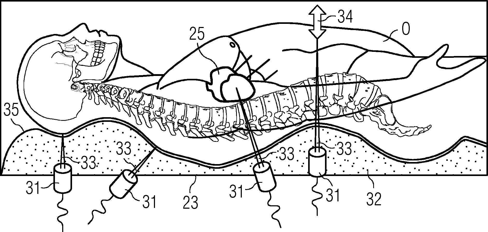
In
Mehrere Ultraschallsensoren
Während der Datenerfassung der Magnetresonanzanlage wird periodisch reihum jeweils einer der Ultraschallsensoren
In
In
Mit
Wenn beispielsweise drei Ultraschallsensoren
Dabei wird angenommen dass die Ausbreitungsgeschwindigkeit einer Ultraschallwelle im menschlichen Körper ca. c = 1540 m/s beträgt. Die jeweils geltende Geschwindigkeit kann abhängig von der Dichte und Elastizität des jeweiligen Gewebes, durch welches die Ultraschallwellen laufen, geringfügig von dieser Konstanten c abweichen. In den meisten Fällen wird aber davon ausgegangen, dass die Geschwindigkeit der Ultraschallwellen durch Gewebe gleich der Geschwindigkeit der Ultraschallwellen durch Flüssigkeiten, wie beispielsweise Wasser, ist. It is assumed that the propagation velocity of an ultrasonic wave in the human body is c = 1540 m / s. Depending on the density and elasticity of the respective tissue through which the ultrasound waves pass, the current speed may slightly deviate from this constant c. In most cases, however, it is believed that the speed of ultrasonic waves through tissue is equal to the velocity of ultrasonic waves through liquids, such as water.
In
Das erste Maximum
Anhand der gemessenen Zeitintervalle tb, tf und ts kann unter Kenntnis der Ausbreitungsgeschwindigkeit c von Ultraschallwellen über die folgende Gleichung (1) der Abstand zu dem jeweiligen Objekt berechnet werden. Dabei beginnt jeder Zeitintervall beim Aussenden des Ultraschallwellen-Pulses und endet mit dem Empfang des entsprechenden Echos, weshalb in der Gleichung (1) das Produkt aus dem Zeitintervall tx und der Ausbreitungsgeschwindigkeit c halbiert wird.
In
Beim Koaxialkabel
Darüber hinaus umfasst der Ultraschallwellensensor
Innerhalb des Gehäuses
In
Der kapazitive Sensor
ZITATE ENTHALTEN IN DER BESCHREIBUNG QUOTES INCLUDE IN THE DESCRIPTION
Diese Liste der vom Anmelder aufgeführten Dokumente wurde automatisiert erzeugt und ist ausschließlich zur besseren Information des Lesers aufgenommen. Die Liste ist nicht Bestandteil der deutschen Patent- bzw. Gebrauchsmusteranmeldung. Das DPMA übernimmt keinerlei Haftung für etwaige Fehler oder Auslassungen.This list of the documents listed by the applicant has been generated automatically and is included solely for the better information of the reader. The list is not part of the German patent or utility model application. The DPMA assumes no liability for any errors or omissions.
Zitierte PatentliteraturCited patent literature
- US 2005/0171425 A1 [0019] US 2005/0171425 A1 [0019]
Claims (15)
Priority Applications (2)
| Application Number | Priority Date | Filing Date | Title |
|---|---|---|---|
| DE102014201585.5A DE102014201585A1 (en) | 2014-01-29 | 2014-01-29 | Device for positioning an examination object, method for creating an image with an imaging system and imaging system |
| US14/607,896 US10182741B2 (en) | 2014-01-29 | 2015-01-28 | Device for positioning an examination object, method for creating an image with the aid of an imaging system, and imaging system |
Applications Claiming Priority (1)
| Application Number | Priority Date | Filing Date | Title |
|---|---|---|---|
| DE102014201585.5A DE102014201585A1 (en) | 2014-01-29 | 2014-01-29 | Device for positioning an examination object, method for creating an image with an imaging system and imaging system |
Publications (1)
| Publication Number | Publication Date |
|---|---|
| DE102014201585A1 true DE102014201585A1 (en) | 2015-07-30 |
Family
ID=53522977
Family Applications (1)
| Application Number | Title | Priority Date | Filing Date |
|---|---|---|---|
| DE102014201585.5A Withdrawn DE102014201585A1 (en) | 2014-01-29 | 2014-01-29 | Device for positioning an examination object, method for creating an image with an imaging system and imaging system |
Country Status (2)
| Country | Link |
|---|---|
| US (1) | US10182741B2 (en) |
| DE (1) | DE102014201585A1 (en) |
Cited By (2)
| Publication number | Priority date | Publication date | Assignee | Title |
|---|---|---|---|---|
| DE102021202118A1 (en) | 2021-03-04 | 2022-09-08 | Siemens Healthcare Gmbh | Imaging device, local coil and method for correcting a movement of a patient |
| DE102023119962A1 (en) | 2023-07-27 | 2025-01-30 | Fraunhofer-Gesellschaft zur Förderung der angewandten Forschung eingetragener Verein | RECLINING DEVICE, SYSTEM COMPRISING THE SAME AND DEVICE AND METHOD FOR EXTERNALLY CONTROLLING THE MOVEMENT OF AT LEAST ONE ULTRASONIC TRANSDUCER OF A RECLINING DEVICE |
Families Citing this family (4)
| Publication number | Priority date | Publication date | Assignee | Title |
|---|---|---|---|---|
| US8970217B1 (en) | 2010-04-14 | 2015-03-03 | Hypres, Inc. | System and method for noise reduction in magnetic resonance imaging |
| DE102012216292B4 (en) * | 2012-09-13 | 2021-02-18 | Siemens Healthcare Gmbh | Magnetic resonance assembly, a magnetic resonance device with the magnetic resonance assembly and a method for determining a movement of a patient during a magnetic resonance examination |
| US10548532B2 (en) * | 2014-11-12 | 2020-02-04 | Shanghai United Imaging Healthcare Co., Ltd. | Transport apparatus in medical system |
| JP6771993B2 (en) * | 2016-08-16 | 2020-10-21 | キヤノンメディカルシステムズ株式会社 | Head support device, head coil device and magnetic resonance imaging device |
Citations (3)
| Publication number | Priority date | Publication date | Assignee | Title |
|---|---|---|---|---|
| US20050171425A1 (en) | 2004-01-16 | 2005-08-04 | Phantoms-By-Design | Medical devices having MRI-enhancing encapsulated fluids |
| DE102009043532A1 (en) * | 2009-09-30 | 2010-09-23 | Siemens Aktiengesellschaft | Supporting device for medical examination- and diagnostic device, has pressure distribution determining device for determining pressure distribution of test object supported on supporting device |
| US7945304B2 (en) * | 2001-11-20 | 2011-05-17 | Feinberg David A | Ultrasound within MRI scanners for guidance of MRI pulse sequences |
Family Cites Families (6)
| Publication number | Priority date | Publication date | Assignee | Title |
|---|---|---|---|---|
| US5400787A (en) | 1993-11-24 | 1995-03-28 | Magna-Lab, Inc. | Inflatable magnetic resonance imaging sensing coil assembly positioning and retaining device and method for using the same |
| US6684096B2 (en) | 2000-12-15 | 2004-01-27 | Berndt P. Schmit | Restraining apparatus and method for use in imaging procedures |
| US7611462B2 (en) * | 2003-05-22 | 2009-11-03 | Insightec-Image Guided Treatment Ltd. | Acoustic beam forming in phased arrays including large numbers of transducer elements |
| US7450985B2 (en) | 2006-05-16 | 2008-11-11 | Mary Jane Meloy | Head restraint system for medical research, diagnosis and operation |
| WO2007136745A2 (en) | 2006-05-19 | 2007-11-29 | University Of Hawaii | Motion tracking system for real time adaptive imaging and spectroscopy |
| US8390291B2 (en) | 2008-05-19 | 2013-03-05 | The Board Of Regents, The University Of Texas System | Apparatus and method for tracking movement of a target |
-
2014
- 2014-01-29 DE DE102014201585.5A patent/DE102014201585A1/en not_active Withdrawn
-
2015
- 2015-01-28 US US14/607,896 patent/US10182741B2/en active Active
Patent Citations (3)
| Publication number | Priority date | Publication date | Assignee | Title |
|---|---|---|---|---|
| US7945304B2 (en) * | 2001-11-20 | 2011-05-17 | Feinberg David A | Ultrasound within MRI scanners for guidance of MRI pulse sequences |
| US20050171425A1 (en) | 2004-01-16 | 2005-08-04 | Phantoms-By-Design | Medical devices having MRI-enhancing encapsulated fluids |
| DE102009043532A1 (en) * | 2009-09-30 | 2010-09-23 | Siemens Aktiengesellschaft | Supporting device for medical examination- and diagnostic device, has pressure distribution determining device for determining pressure distribution of test object supported on supporting device |
Cited By (3)
| Publication number | Priority date | Publication date | Assignee | Title |
|---|---|---|---|---|
| DE102021202118A1 (en) | 2021-03-04 | 2022-09-08 | Siemens Healthcare Gmbh | Imaging device, local coil and method for correcting a movement of a patient |
| US11998361B2 (en) | 2021-03-04 | 2024-06-04 | Siemens Healthineers Ag | Imaging apparatus, local coil and method for correcting a patient movement |
| DE102023119962A1 (en) | 2023-07-27 | 2025-01-30 | Fraunhofer-Gesellschaft zur Förderung der angewandten Forschung eingetragener Verein | RECLINING DEVICE, SYSTEM COMPRISING THE SAME AND DEVICE AND METHOD FOR EXTERNALLY CONTROLLING THE MOVEMENT OF AT LEAST ONE ULTRASONIC TRANSDUCER OF A RECLINING DEVICE |
Also Published As
| Publication number | Publication date |
|---|---|
| US10182741B2 (en) | 2019-01-22 |
| US20150208946A1 (en) | 2015-07-30 |
Similar Documents
| Publication | Publication Date | Title |
|---|---|---|
| DE102015203385B4 (en) | Method for generating motion information to an at least partially moving examination area and magnetic resonance system and hybrid imaging modality | |
| DE69524839T2 (en) | Imaging of the synchronized spin movement and the expansion waves by means of magnetic resonance | |
| DE102011079565B4 (en) | Direct connection head coil with height adjustment for e.g. Bechterew patients | |
| DE60318438T2 (en) | BLOOD FLOW GATE MRI | |
| DE102011076885B4 (en) | Method for controlling a medical device, device with a medical device and data carrier | |
| DE102014201585A1 (en) | Device for positioning an examination object, method for creating an image with an imaging system and imaging system | |
| DE102012215718B4 (en) | Method and magnetic resonance system for MR imaging of a predetermined volume section of a living examination subject by stimulating the examination subject | |
| DE102008019862B4 (en) | Magnetic resonance apparatus and method for operating a magnetic resonance apparatus | |
| DE102011001292A1 (en) | System and method for automatically calculating MR imaging scan parameters | |
| DE102011083619B4 (en) | Method for generating a series of MR images for monitoring a position of an intervention device, magnetic resonance system and electronically readable data carrier located in an examination area | |
| DE102010017315A1 (en) | System, method and apparatus for measuring a magnetic resonance (RF) field | |
| EP2946730A1 (en) | Method for measuring the breathing process of a patient undergoing a magnetic resonance examination, measuring device and magnetic resonance device | |
| DE102005061567B3 (en) | Method, device and computer program product for adjusting the field strength of high-frequency pulses and a magnetic resonance measuring system | |
| DE112016005183T5 (en) | Magnetic resonance examination system with a user interface | |
| DE102008044827B3 (en) | Method and device for generating a time-frame-adapted measurement sequence for a magnetic resonance scanner, which can be executed on a time grid of the magnetic resonance scanner | |
| DE102014226034B4 (en) | Image correction in MR imaging taking into account the reception profile | |
| DE102015203306A1 (en) | Method for determining absolute reception sensitivity maps for receiving coils in a magnetic resonance device and magnetic resonance device | |
| DE102012213696A1 (en) | Magnetic resonance imaging coordinated with a physiological cycle | |
| DE102015203932B4 (en) | Attenuation correction of emission tomography measurement data in the presence of a magnetic interference field | |
| DE102007004620B4 (en) | Improved three-dimensional slice-selective multi-slice excitation in MRI imaging | |
| DE102012204527B4 (en) | Multi-ply cushion for optimal adaptation to anatomy and susceptibility adjustment | |
| DE102011006150B4 (en) | Magnetic resonance system and method for performing magnetic resonance measurements in an intra-oral area | |
| DE102014217730A1 (en) | A method of imaging an examination subject by means of a combined magnetic resonance emission tomography apparatus | |
| DE102014210657A1 (en) | Axis-displaceable local coil | |
| DE102011075440B4 (en) | Head support cushion with integrated patient fixation |
Legal Events
| Date | Code | Title | Description |
|---|---|---|---|
| R012 | Request for examination validly filed | ||
| R016 | Response to examination communication | ||
| R081 | Change of applicant/patentee |
Owner name: SIEMENS HEALTHCARE GMBH, DE Free format text: FORMER OWNER: SIEMENS AKTIENGESELLSCHAFT, 80333 MUENCHEN, DE |
|
| R119 | Application deemed withdrawn, or ip right lapsed, due to non-payment of renewal fee |