DE102014117176A1 - Pedicle screw system and spine stabilization system - Google Patents
Pedicle screw system and spine stabilization system Download PDFInfo
- Publication number
- DE102014117176A1 DE102014117176A1 DE102014117176.4A DE102014117176A DE102014117176A1 DE 102014117176 A1 DE102014117176 A1 DE 102014117176A1 DE 102014117176 A DE102014117176 A DE 102014117176A DE 102014117176 A1 DE102014117176 A1 DE 102014117176A1
- Authority
- DE
- Germany
- Prior art keywords
- coupling
- screw
- pedicle screw
- bone
- pedicle
- Prior art date
- Legal status (The legal status is an assumption and is not a legal conclusion. Google has not performed a legal analysis and makes no representation as to the accuracy of the status listed.)
- Withdrawn
Links
- 230000006641 stabilisation Effects 0.000 title claims abstract description 19
- 238000011105 stabilization Methods 0.000 title claims abstract description 19
- 230000008878 coupling Effects 0.000 claims abstract description 146
- 238000010168 coupling process Methods 0.000 claims abstract description 146
- 238000005859 coupling reaction Methods 0.000 claims abstract description 146
- 210000000988 bone and bone Anatomy 0.000 claims abstract description 121
- 238000003780 insertion Methods 0.000 description 23
- 230000037431 insertion Effects 0.000 description 23
- 210000002414 leg Anatomy 0.000 description 22
- 230000000903 blocking effect Effects 0.000 description 6
- 238000013461 design Methods 0.000 description 5
- 230000002349 favourable effect Effects 0.000 description 5
- 241000309551 Arthraxon hispidus Species 0.000 description 3
- 238000012937 correction Methods 0.000 description 2
- BUHVIAUBTBOHAG-FOYDDCNASA-N (2r,3r,4s,5r)-2-[6-[[2-(3,5-dimethoxyphenyl)-2-(2-methylphenyl)ethyl]amino]purin-9-yl]-5-(hydroxymethyl)oxolane-3,4-diol Chemical compound COC1=CC(OC)=CC(C(CNC=2C=3N=CN(C=3N=CN=2)[C@H]2[C@@H]([C@H](O)[C@@H](CO)O2)O)C=2C(=CC=CC=2)C)=C1 BUHVIAUBTBOHAG-FOYDDCNASA-N 0.000 description 1
- 241000722921 Tulipa gesneriana Species 0.000 description 1
- 230000005540 biological transmission Effects 0.000 description 1
- 230000015572 biosynthetic process Effects 0.000 description 1
- 238000005266 casting Methods 0.000 description 1
- 238000011161 development Methods 0.000 description 1
- 230000009365 direct transmission Effects 0.000 description 1
- 238000005553 drilling Methods 0.000 description 1
- 238000002513 implantation Methods 0.000 description 1
- 238000003754 machining Methods 0.000 description 1
- 238000000034 method Methods 0.000 description 1
- 238000012978 minimally invasive surgical procedure Methods 0.000 description 1
- 238000010079 rubber tapping Methods 0.000 description 1
- 238000007493 shaping process Methods 0.000 description 1
- 210000000689 upper leg Anatomy 0.000 description 1
Images


Classifications
-
- A—HUMAN NECESSITIES
- A61—MEDICAL OR VETERINARY SCIENCE; HYGIENE
- A61B—DIAGNOSIS; SURGERY; IDENTIFICATION
- A61B17/00—Surgical instruments, devices or methods
- A61B17/56—Surgical instruments or methods for treatment of bones or joints; Devices specially adapted therefor
- A61B17/58—Surgical instruments or methods for treatment of bones or joints; Devices specially adapted therefor for osteosynthesis, e.g. bone plates, screws or setting implements
- A61B17/68—Internal fixation devices, including fasteners and spinal fixators, even if a part thereof projects from the skin
- A61B17/70—Spinal positioners or stabilisers, e.g. stabilisers comprising fluid filler in an implant
- A61B17/7001—Screws or hooks combined with longitudinal elements which do not contact vertebrae
- A61B17/7035—Screws or hooks, wherein a rod-clamping part and a bone-anchoring part can pivot relative to each other
- A61B17/7037—Screws or hooks, wherein a rod-clamping part and a bone-anchoring part can pivot relative to each other wherein pivoting is blocked when the rod is clamped
-
- A—HUMAN NECESSITIES
- A61—MEDICAL OR VETERINARY SCIENCE; HYGIENE
- A61B—DIAGNOSIS; SURGERY; IDENTIFICATION
- A61B17/00—Surgical instruments, devices or methods
- A61B17/56—Surgical instruments or methods for treatment of bones or joints; Devices specially adapted therefor
- A61B17/58—Surgical instruments or methods for treatment of bones or joints; Devices specially adapted therefor for osteosynthesis, e.g. bone plates, screws or setting implements
- A61B17/68—Internal fixation devices, including fasteners and spinal fixators, even if a part thereof projects from the skin
- A61B17/70—Spinal positioners or stabilisers, e.g. stabilisers comprising fluid filler in an implant
- A61B17/7001—Screws or hooks combined with longitudinal elements which do not contact vertebrae
- A61B17/7032—Screws or hooks with U-shaped head or back through which longitudinal rods pass
-
- A—HUMAN NECESSITIES
- A61—MEDICAL OR VETERINARY SCIENCE; HYGIENE
- A61B—DIAGNOSIS; SURGERY; IDENTIFICATION
- A61B17/00—Surgical instruments, devices or methods
- A61B17/56—Surgical instruments or methods for treatment of bones or joints; Devices specially adapted therefor
- A61B17/58—Surgical instruments or methods for treatment of bones or joints; Devices specially adapted therefor for osteosynthesis, e.g. bone plates, screws or setting implements
- A61B17/68—Internal fixation devices, including fasteners and spinal fixators, even if a part thereof projects from the skin
- A61B17/70—Spinal positioners or stabilisers, e.g. stabilisers comprising fluid filler in an implant
- A61B17/7001—Screws or hooks combined with longitudinal elements which do not contact vertebrae
- A61B17/7035—Screws or hooks, wherein a rod-clamping part and a bone-anchoring part can pivot relative to each other
-
- A—HUMAN NECESSITIES
- A61—MEDICAL OR VETERINARY SCIENCE; HYGIENE
- A61B—DIAGNOSIS; SURGERY; IDENTIFICATION
- A61B17/00—Surgical instruments, devices or methods
- A61B17/56—Surgical instruments or methods for treatment of bones or joints; Devices specially adapted therefor
- A61B17/58—Surgical instruments or methods for treatment of bones or joints; Devices specially adapted therefor for osteosynthesis, e.g. bone plates, screws or setting implements
- A61B17/68—Internal fixation devices, including fasteners and spinal fixators, even if a part thereof projects from the skin
- A61B17/70—Spinal positioners or stabilisers, e.g. stabilisers comprising fluid filler in an implant
- A61B17/7074—Tools specially adapted for spinal fixation operations other than for bone removal or filler handling
- A61B17/7076—Tools specially adapted for spinal fixation operations other than for bone removal or filler handling for driving, positioning or assembling spinal clamps or bone anchors specially adapted for spinal fixation
- A61B17/7077—Tools specially adapted for spinal fixation operations other than for bone removal or filler handling for driving, positioning or assembling spinal clamps or bone anchors specially adapted for spinal fixation for moving bone anchors attached to vertebrae, thereby displacing the vertebrae
Landscapes
- Health & Medical Sciences (AREA)
- Orthopedic Medicine & Surgery (AREA)
- Neurology (AREA)
- Life Sciences & Earth Sciences (AREA)
- Surgery (AREA)
- Heart & Thoracic Surgery (AREA)
- Engineering & Computer Science (AREA)
- Biomedical Technology (AREA)
- Nuclear Medicine, Radiotherapy & Molecular Imaging (AREA)
- Medical Informatics (AREA)
- Molecular Biology (AREA)
- Animal Behavior & Ethology (AREA)
- General Health & Medical Sciences (AREA)
- Public Health (AREA)
- Veterinary Medicine (AREA)
- Surgical Instruments (AREA)
Abstract
Um ein Pedikelschraubensystem umfassend eine Pedikelschraube mit einem Schraubenschaft, welcher ein Außengewinde aufweist, und einem kugelgelenkig am Schraubenschaft gelagerten Schraubenkopf, welcher Schraubenkopf eine Verbindungselementaufnahme für ein Verbindungselement eines Wirbelsäulenstabilisierungssystems umfasst, so zu verbessern, dass dessen Handhabung verbessert wird, wird vorgeschlagen, dass es eine Knochenausrichtvorrichtung und eine Kopplungseinrichtung zum kraft- und/oder formschlüssigen Koppeln der Knochenausrichtvorrichtung und der Pedikelschraube in einer Ausrichtstellung, in welcher eine Beweglichkeit des Schraubenkopfs und des Schraubenschafts von drei Bewegungsfreiheitsgraden der Rotation des kugelgelenkig am Schraubenschaft gelagerten Schraubenkopfs um mindestens einen Rotationsfreiheitsgrad reduziert ist.
Ferner wird ein verbessertes Wirbelsäulenstabilisierungssystem vorgeschlagen.In order to improve a pedicle screw system comprising a pedicle screw having a screw shank having an external thread and a screw head mounted ball-like on the screw shaft, which screw head comprises a connector receptacle for a connecting element of a spinal stabilization system, so as to improve its handling, it is proposed that it be a Bone alignment device and a coupling device for non-positive and / or positive coupling of the bone alignment device and the pedicle screw in an alignment position in which a mobility of the screw head and the screw shaft of three degrees of freedom of rotation of the ball joint mounted on the screw shaft screw head is reduced by at least one rotational degree of freedom.
Furthermore, an improved spine stabilization system is proposed.
Description
Die vorliegende Erfindung betrifft ein Pedikelschraubensystem umfassend eine Pedikelschraube mit einem Schraubenschaft, welcher ein Außengewinde aufweist, und einem kugelgelenkig am Schraubenschaft gelagerten Schraubenkopf, welcher Schraubenkopf eine Verbindungselementaufnahme für ein Verbindungselement eines Wirbelsäulenstabilisierungssystems umfasst.The present invention relates to a pedicle screw system comprising a pedicle screw with a screw shaft which has an external thread, and a ball head mounted on the screw shaft screw head, which screw head comprises a connection element receptacle for a connecting element of a spine stabilization system.
Ferner betrifft die vorliegende Erfindung ein Wirbelsäulenstabilisierungssystem umfassend mindestens zwei Knochenschrauben und mindestens ein an den mindestens zwei Knochenschrauben festlegbares Verbindungselement.Furthermore, the present invention relates to a spine stabilization system comprising at least two bone screws and at least one fixable to the at least two bone screws connecting element.
Pedikelschrauben und Wirbelsäulenstabilisierungssysteme der eingangs beschriebenen Art sind beispielsweise aus der
Bei Pedikelschraubensystemen, bei denen ein Verbindungselement von oben in eine entsprechende Verbindungselementaufnahme am Schraubenkopf eingesetzt werden kann, also bei sogenannten "Tulpen"-Systemen, ist eine Krafteinleitung nicht möglich, wenn die Pedikelschraube in Form einer Polyaxialschraube ausgebildet ist. Eine Krafteinleitung ist nur möglich, wenn der Schraubenkopf relativ zum Schraubenschaft unbeweglich oder maximal um eine Achse verschwenkbar ist, es sich also bei der Pedikelschraube um eine sogenannte Monoaxialschraube handelt. Der Schraubenkopf wird dabei in einer Ebene bewegt, welche senkrecht zur Achse, um die verschwenkt wird, verläuft, so dass die Monoaxialschraube in diesem Sinne auch als Uniplanarschraube bezeichnet werden kann. Bei Polyaxialschrauben hingegen, die das Einsetzen des Verbindungselements, beispielsweise eines Stabs, deutlich dadurch vereinfachen, dass der Schraubenkopf beliebig relativ zum Schraubenschaft orientiert werden kann, ist eine solche Krafteinleitung und Korrektur einer Ausrichtung eines Wirbels nicht oder nur rudimentär möglich. Insbesondere ist es nicht möglich, die Technik der segmentalen Derotation bei Polyaxialschrauben anzuwenden. Diese ist nur bei direkter Krafteinleitung in die Pedikelschraube, wie es insbesondere die beschriebenen Monoaxialschrauben ermöglichen, realisierbar. In pedicle screw systems in which a connecting element can be inserted from above into a corresponding connecting element receptacle on the screw head, that is in so-called "tulip" systems, a force introduction is not possible if the pedicle screw is designed in the form of a polyaxial screw. An introduction of force is only possible if the screw head is immovable relative to the screw shaft or at most pivotable about an axis, so it is in the pedicle screw is a so-called monoaxial screw. The screw head is thereby moved in a plane which is perpendicular to the axis about which is pivoted, runs, so that the monoaxial screw can be referred to in this sense as a uniplanar screw. In contrast, in polyaxial screws, which simplify the insertion of the connecting element, such as a rod, significantly by the fact that the screw head can be arbitrarily oriented relative to the screw shaft, such force application and correction of alignment of a vortex is not or only possible rudimentary. In particular, it is not possible to apply the technique of segmental derotation in polyaxial screws. This can only be achieved with a direct introduction of force into the pedicle screw, as is possible in particular by the monoaxial screws described.
Es ist daher eine Aufgabe der vorliegenden Erfindung, ein Pedikelschraubensystem und ein Wirbelsäulenstabilisierungssystem der eingangs beschriebenen Art so weiter zu bilden, dass deren Handhabung verbessert wird. It is therefore an object of the present invention to further develop a pedicle screw system and a spinal stabilization system of the type described in the opening paragraph so that their handling is improved.
Diese Aufgabe wird bei einem Pedikelschraubensystem der eingangs beschriebenen Art erfindungsgemäß dadurch gelöst, dass es eine Knochenausrichtvorrichtung und eine Kopplungseinrichtung zum kraft- und/oder formschlüssigen Koppeln der Knochenausrichtvorrichtung und der Pedikelschraube in einer Ausrichtstellung, in welcher eine Beweglichkeit des Schraubenkopfs und des Schraubenschafts von drei Bewegungsfreiheitsgraden der Rotation des kugelgelenkig am Schraubenschaft gelagerten Schraubenkopfs um mindestens einen Rotationsfreiheitsgrad reduziert ist. This object is achieved in a pedicle screw system of the type described above according to the invention that there is a bone alignment and a coupling device for non-positive and / or positive coupling the Knochenausrichtvorrichtung and the pedicle screw in an alignment position in which a mobility of the screw head and the screw shaft of three degrees of freedom the rotation of the ball joint mounted on the screw shaft screw head is reduced by at least one rotational degree of freedom.
Die erfindungsgemäß vorgeschlagene Weiterbildung ermöglicht es dem Operateur insbesondere, über die Knochenausrichtvorrichtung Kräfte zum Bewegen, insbesondere Rotieren, deformierter Wirbel einer Wirbelsäule direkt auf den Schraubenschaft einzuleiten, wenn die Kopplungsvorrichtung des Pedikelschraubensystems die Ausrichtstellung einnimmt. Das vorgeschlagene Pedikelschraubensystem vereinigt somit einerseits die Vorteile von Polyaxialschrauben, die eine beliebige Ausrichtung des Schraubenkopfs relativ zum Schraubenschaft ermöglichen, um das Einsetzen des Verbindungselements in die Verbindungselementaufnahme am Schraubenkopf zu erleichtern, und andererseits, insbesondere bei der Beschränkung der Bewegungsfreiheitsgrade der Rotation auf einen Rotationsfreiheitsgrad, die Vorteile einer Monoaxialschraube, die das Einleiten von Kräften auf den Schraubenschaft zur Ausrichtung eines Wirbelkörpers, in den Pedikelschrauben eingeschraubt ist, ermöglicht. Insbesondere kann die Zahl der ursprünglich drei Bewegungsfreiheitsgrade der Rotation auf keinen, einen oder zwei Bewegungsfreiheitsgrade der Rotation beschränkt sein.The development proposed according to the invention makes it possible for the surgeon, in particular, to initiate forces for moving, in particular rotating, deformed vertebrae of a spinal column directly onto the screw shaft via the bone alignment device, when the coupling device of the pedicle screw system assumes the alignment position. The proposed pedicle screw system thus combines, on the one hand, the advantages of polyaxial screws which allow any orientation of the screw head relative to the screw shaft to facilitate insertion of the connecting element into the connector receptacle on the screw head and, on the other hand, particularly in restricting the degrees of freedom of rotation to a rotational degree of freedom. the advantages of a monoaxial screw, which allows the introduction of forces on the screw shaft for aligning a vertebral body is screwed into the pedicle screws. In particular, the number of originally three degrees of freedom of rotation may be limited to none, one or two degrees of freedom of rotation.
Durch die Kopplung der Knochenausrichtvorrichtung und der Pedikelschraube in der Ausrichtstellung wird insbesondere temporär eine Anordnung geschaffen, die in ihrer Funktion einer Monoaxialschraube entspricht. Von den ursprünglich drei Bewegungsfreiheitsgraden, die die kugelgelenkige Verbindung zwischen dem Schraubenschaft und dem Schraubenkopf ermöglicht, wird durch die Kopplung der Pedikelschraube und der Knochenausrichtvorrichtung in der Ausrichtstellung die Zahl der Bewegungsfreiheitsgrade zwischen Schraubenschaft und Schraubenkopf auf einen Bewegungsfreiheitsgrad der Rotation reduziert. Dies entspricht einer Rotation des Schraubenschafts und des Schraubenkopfs relativ zueinander um lediglich eine einzige Schwenkachse. Durch die Kopplungseinrichtung kann insbesondere eine axiale und/oder drehfeste Verbindung zwischen der Knochenausrichtvorrichtung und der Pedikelschraube hergestellt und somit über die Knochenausrichtvorrichtung eine indirekte Kraftübertragung beispielsweise von der Knochenausrichtvorrichtung auf den Schraubenschaft ermöglicht werden. By the coupling of the bone alignment device and the pedicle screw in the alignment position, in particular a temporary arrangement is created which corresponds in its function to a monoaxial screw. Of the original three degrees of freedom of movement that the ball-and-socket joint between the screw shaft and the screw head allows, the coupling of the pedicle screw and the bone alignment device in the alignment position reduces the number of degrees of freedom of movement between the screw shaft and screw head to a degree of freedom of rotation. This corresponds to a rotation of the screw shaft and the screw head relative to each other by only a single pivot axis. In particular, an axial and / or rotationally fixed connection between the bone alignment device and the pedicle screw can be produced by the coupling device and thus via the Bone alignment device allows an indirect force transmission, for example, from the Knochenausrichtvorrichtung on the screw shaft.
Günstig ist es, wenn die Knochenausrichtvorrichtung in Form einer Klemmplatte ausgebildet ist oder eine Klemmplatte umfasst. Beispielsweise kann die Klemmplatte an der Pedikelschraube zwischen dem Schraubenkopf und dem Außengewinde klemmend angeordnet werden, um so eine freie Rotation des Schraubenkopfs relativ zum Schraubenschaft teilweise zu blockieren und nur noch eine Verschwenkbewegung um eine einzige Schwenkachse, wie dies bei eine Monoaxialschraube der Fall ist, zu gestatten. It is favorable if the bone alignment device is designed in the form of a clamping plate or comprises a clamping plate. For example, the clamping plate can be clamped to the pedicle screw between the screw head and the external thread so as to partially block a free rotation of the screw head relative to the screw shaft and only a pivoting movement about a single pivot axis, as is the case with a monoaxial screw to allow.
Vorteilhaft ist es, wenn die Kopplungseinrichtung erste und zweite Kopplungselemente umfasst, welche in der Ausrichtstellung kraft- und/oder formschlüssig in Eingriff stehen und einerseits an der Knochenausrichtvorrichtung und andererseits an der Pedikelschraube angeordnet oder ausgebildet sind. Mit einer solchen Kopplungseinrichtung kann die Knochenausrichtvorrichtung mit der Pedikelschraube auf einfache und sichere Weise in Eingriff gebracht werden. It is advantageous if the coupling device comprises first and second coupling elements, which are non-positively and / or positively engaged in the alignment position and arranged or formed on the one hand on the Knochenausrichtvorrichtung and on the other hand on the pedicle screw. With such a coupling device, the bone alignment device can be engaged with the pedicle screw in a simple and secure manner.
Vorzugsweise sind das erste Kopplungselement in Form eines Kopplungsvorsprungs und das zweite Kopplungselement in Form einer zum Kopplungsvorsprung korrespondierenden Kopplungsaufnahme ausgebildet. Derartige Kopplungselemente lassen sich auf einfache Weise ausbilden und wahlweise an der Pedikelschraube oder an der Knochenausrichtvorrichtung anordnen oder ausbilden. Preferably, the first coupling element in the form of a coupling projection and the second coupling element in the form of a coupling projection corresponding to the coupling receptacle are formed. Such coupling elements can be formed in a simple manner and either arrange or form on the pedicle screw or on the bone alignment device.
Um insbesondere ein unbeabsichtigtes Ablösen der Knochenausrichtvorrichtung von der Pedikelschraube in der Ausrichtstellung zu vermeiden oder ein Risiko hierfür zu minimieren, ist es vorteilhaft, wenn der Kopplungsvorsprung in der Ausrichtstellung formschlüssig oder im Wesentlichen formschlüssig in die Kopplungsaufnahme eingreift. In order in particular to avoid unintentional detachment of the bone alignment device from the pedicle screw in the alignment position or to minimize a risk for this, it is advantageous if the coupling projection in the alignment position engages positively or substantially positively in the coupling receptacle.
Ein besonders stabiles Pedikelschraubensystem lässt sich insbesondere dadurch erhalten, dass der Kopplungsvorsprung einstückig mit dem Schraubenschaft ausgebildet ist. A particularly stable pedicle screw system can be obtained in particular in that the coupling projection is formed integrally with the screw shaft.
Auf besonders einfache Weise herstellen lässt sich das Pedikelschraubensystem, wenn der Kopplungsvorsprung in Form eines gewindefreien Schaftabschnitts des Schraubenschafts ausgebildet ist. Der gewindefreie Schaftabschnitt kann insbesondere einen kreisförmigen Querschnitt aufweisen oder einen unrunden Querschnitt, beispielsweise in Form eines Ovals, eines Vielrunds oder eines Vielecks. So kann beispielsweise bei einem kreisförmigen Querschnitt eine Verdrehung zwischen der Knochenausrichtvorrichtung und der Pedikelschraube ermöglicht werden oder aber auch eine drehfeste Verbindung mit einem unrunden Querschnitt hergestellt werden. The pedicle screw system can be produced in a particularly simple manner if the coupling projection is designed in the form of a thread-free shaft section of the screw shaft. The unthreaded shaft portion may in particular have a circular cross section or a non-circular cross section, for example in the form of an oval, a polygon or a polygon. Thus, for example, in the case of a circular cross section, a rotation between the bone alignment device and the pedicle screw can be made possible, or a non-rotatable connection with a non-circular cross section can also be produced.
Gemäß einer weiteren bevorzugten Ausführungsform der Erfindung kann vorgesehen sein, dass der Schraubenschaft einen Gelenkkopf aufweist und dass der Schraubenkopf eine zum Gelenkkopf korrespondierende Gelenkkopfaufnahme zur Ausbildung eines Kugelgelenks im Zusammenwirken mit dem Gelenkkopf aufweist. Durch den Gelenkkopf im Zusammenwirken mit der Gelenkkopfaufnahme kann so auf einfache Weise ein Kugelgelenk gebildet werden. Der Gelenkkopf kann insbesondere die Form einer Kugel oder eines Teils einer Kugel aufweisen. Die Gelenkkopfaufnahme kann insbesondere in Form eines zu einer Gelenkkugel korrespondierenden hohlkugeligen Sitzes geformt sein. According to a further preferred embodiment of the invention can be provided that the screw shaft has a condyle and that the screw head has a condyle corresponding to the condyle head receptacle for forming a ball joint in cooperation with the condyle. By the condyle in cooperation with the condyle receptacle so a ball joint can be formed in a simple manner. The condyle may in particular have the shape of a ball or a part of a ball. The condyle receptacle can in particular be shaped in the form of a hollow spherical seat corresponding to a joint ball.
Auf einfache Weise lassen sich Rotationsfreiheitsgrade zwischen dem Schraubenkopf und dem Schraubenschaft ausschalten, wenn der Kopplungsvorsprung zwischen dem Außengewinde und dem Gelenkkopf angeordnet ist. Beispielsweise kann so mit der Knochenausrichtvorrichtung eine Bewegung des Schraubenkopfs relativ zum Schraubenschaft auf einfache Weise blockiert werden, beispielsweise durch eine klemmende Verbindung. In a simple way, rotational degrees of freedom between the screw head and the screw shank can be switched off if the coupling projection is arranged between the external thread and the condyle. For example, with the bone alignment device, movement of the screw head relative to the screw shaft can be blocked in a simple manner, for example by a clamping connection.
Vorteilhaft ist es, wenn die Kopplungseinrichtung ein Anschlagelement umfasst, an welchem sich die Knochenausrichtvorrichtung in der Ausrichtstellung abstützt. Beispielsweise kann das Anschlagelement am Schraubenschaft ausgebildet sein, sodass sich die Knochenausrichtvorrichtung einerseits am Anschlagelement und andererseits am Schraubenkopf abstützen kann. It is advantageous if the coupling device comprises a stop element on which the bone alignment device is supported in the alignment position. For example, the stop element may be formed on the screw shaft, so that the bone alignment device can be supported on the one hand on the stop element and on the other hand on the screw head.
Günstigerweise weist die Knochenausrichtvorrichtung eine Anschlagelementanlagefläche auf, welche in der Ausrichtstellung am Anschlagelement anliegt. Dies ermöglicht es insbesondere, dass sich die Knochenausrichtvorrichtung in der Ausrichtstellung direkt am Anschlagelement abstützt. Wenn sich die Knochenausrichtvorrichtung andererseits am Schraubenkopf abstützen kann, kann eine Beweglichkeit des Schraubenkopfs relativ zum Schraubenschaft auf einfache Weise eingeschränkt werden.Conveniently, the bone alignment device has a stop element abutment surface, which rests against the stop element in the alignment position. This makes it possible, in particular, for the bone alignment device to be supported directly on the stop element in the alignment position. On the other hand, if the bone aligning device can be supported on the screw head, mobility of the screw head relative to the screw shaft can be easily restricted.
Vorzugsweise ist die Anschlagelementanlagefläche eben oder im Wesentlichen eben ausgebildet. Diese Ausgestaltung ermöglicht insbesondere eine flächige Anlage am Anschlagelement, wenn dieses eine ebene oder im Wesentlichen ebene Anschlagfläche aufweist, an welcher die Anschlagelementanlagefläche in der Ausrichtstellung anliegt. Preferably, the stop element abutment surface is flat or substantially planar. In particular, this embodiment makes it possible to engage in a planar manner on the stop element when the latter has a flat or essentially flat stop surface against which the stop element contact surface rests in the alignment position.
Günstig ist es, wenn das Anschlagelement eine ebene oder im Wesentlichen ebene Anschlagfläche aufweist, an welcher sich die Knochenausrichtvorrichtung in der Ausrichtstellung abstützt. Eine solche Anschlagfläche ist auf einfache Weise auszubilden und ermöglicht eine flächige Anlage der Knochenausrichtvorrichtung am Anschlagelement, wenn die Anschlagelementanlagefläche eben oder im Wesentlichen eben ausgebildet ist. It is advantageous if the stop element has a flat or substantially flat stop surface on which the bone alignment device is supported in the alignment position. A Such abutment surface is formed in a simple manner and allows a flat abutment of the bone alignment device on the stop element, when the stop element abutment surface is flat or substantially planar.
Ein besonders kompakter Aufbau des Pedikelschraubensystems lässt sich insbesondere dadurch erreichen, dass das Anschlagelement am Schraubenschaft angeordnet oder ausgebildet ist. A particularly compact design of the pedicle screw system can be achieved, in particular, by arranging or forming the stop element on the screw shaft.
Besonders einfach herstellen lässt sich der Schraubenschaft, wenn das Anschlagelement in Form eines Ringflansches ausgebildet ist. Beispielsweise kann der Schraubenschaft so durch Gießen oder spannende Bearbeitung hergestellt werden.The screw shaft can be produced particularly easily if the stop element is designed in the form of an annular flange. For example, the screw shaft can be manufactured by casting or exciting machining.
Gemäß einer weiteren bevorzugten Ausführungsform der Erfindung kann vorgesehen sein, dass das Anschlagelement einstückig mit dem Schraubenschaft ausgebildet oder kraft- und/oder stoffschlüssig mit dem Schraubenschaft verbunden ist. Insbesondere kann das Anschlagelement mit dem Schraubenschaft verpresst, verklebt, verlötet oder verschweißt sein. Je nach Art und Ausbildung des Schraubenschafts und des Schraubenkopfs sowie der Art der kugelgelenkigen Verbindung derselben kann es wahlweise vorteilhaft sein, das Anschlagelement einstückig mit dem Schraubenschaft auszubilden oder kraft- und/oder stoffschlüssig mit diesem zu verbinden. According to a further preferred embodiment of the invention can be provided that the stop element is formed integrally with the screw shaft or non-positively and / or materially connected to the screw shaft. In particular, the stop element can be pressed, glued, soldered or welded to the screw shank. Depending on the type and design of the screw shaft and the screw head and the nature of the ball-jointed connection of the same, it may optionally be advantageous to form the stop element in one piece with the screw shaft or to connect it non-positively and / or materially.
Vorteilhaft ist es, wenn ein Außendurchmesser des Anschlagelements größer ist als ein maximaler Außendurchmesser des Außengewindes. So kann sichergestellt werden, dass in der Ausrichtstellung die Knochenausrichtvorrichtung nicht mit dem Außengewinde in Kontakt treten kann. It is advantageous if an outer diameter of the stop element is greater than a maximum outer diameter of the external thread. So it can be ensured that in the alignment position the bone alignment device can not come into contact with the external thread.
Insbesondere bei kurzen Schraubenschäften ist es vorteilhaft, wenn das Anschlagelement direkt an das Außengewinde angrenzt. So kann der Schraubenschaft bis zum Anschlagelement in einen Knochen eingeschraubt werden. Especially with short screw shanks, it is advantageous if the stop element is directly adjacent to the external thread. Thus, the screw shaft can be screwed to the stop element in a bone.
Günstig ist es, wenn der Schraubenkopf eine in Richtung auf das Außengewinde hin weisende Anlagefläche aufweist, an welcher sich die Knochenausrichtvorrichtung in der Ausrichtstellung abstützt. Diese Ausgestaltung ermöglicht insbesondere eine direkte Kraftübertragung von der Knochenausrichtvorrichtung auf den Schraubenkopf beziehungsweise eine direkte Einwirkung auf diesen zum Blockieren von mindestens zwei Rotationsfreiheitsgraden des kugelgelenkig mit dem Schraubenschaft zusammenwirkenden Schraubenkopfs.It is favorable if the screw head has a contact surface pointing in the direction of the external thread, against which the bone alignment device is supported in the alignment position. In particular, this embodiment enables a direct transmission of force from the bone alignment device to the screw head or a direct action thereon for blocking at least two rotational degrees of freedom of the ball head cooperating with the screw shaft.
Auf besonders einfache Weise herstellen lässt sich der Schraubenkopf, wenn die Anlagefläche eben oder im Wesentlichen eben oder vom Schraubenkopf weg weisend konkav gekrümmt ausgebildet ist. Vorzugsweise wird die Anlagefläche derart geformt, dass eine flächige Anlage an der Knochenausrichtvorrichtung möglich ist. The screw head can be produced in a particularly simple manner if the contact surface is flat or substantially planar or curved concavely away from the screw head. Preferably, the contact surface is shaped such that a flat contact with the bone alignment device is possible.
Gemäß einer weiteren bevorzugten Ausführungsform der Erfindung kann vorgesehen sein, dass die Knochenausrichtvorrichtung eine Führungsfläche zum Vorgeben einer Bewegungsrichtung für eine Relativbewegung zwischen dem Schraubenkopf und dem Schraubenschaft aufweist und dass der Schraubenkopf in der Ausrichtstellung an der Führungsfläche anliegt und an dieser um eine Schwenkachse relativ zum Schraubenschaft verschwenkbar geführt ist. Mit der Führungsfläche ist es so insbesondere auf einfache Weise möglich, die gewünschte Relativbewegung zwischen dem Schraubenkopf und dem Schraubenschaft vorzugeben, also insbesondere nur eine Verschwenkbewegung um eine einzige Schwenkachse zuzulassen. Dies kann auf einfache Weise durch Formgebung der Führungsfläche erreicht werden. Insbesondere kann die Führungsfläche in Richtung auf den Schraubenkopf hin weisend konvex gekrümmt sein. Beispielsweise kann sie sich koaxial zur Schwenkachse erstrecken oder kann die Schwenkachse auf der Führungsfläche liegen. According to a further preferred embodiment of the invention, it can be provided that the bone alignment device has a guide surface for specifying a movement direction for a relative movement between the screw head and the screw shaft and that the screw head abuts in the alignment position on the guide surface and at this about a pivot axis relative to the screw shaft is guided pivotally. With the guide surface, it is possible in particular in a simple manner to specify the desired relative movement between the screw head and the screw shank, ie in particular to allow only a pivoting movement about a single pivot axis. This can be achieved in a simple manner by shaping the guide surface. In particular, the guide surface may be convexly curved in the direction of the screw head. For example, it may extend coaxially to the pivot axis or the pivot axis may lie on the guide surface.
Vorzugsweise bildet die Führungsfläche einen Teil einer Zylinderoberfläche. Günstigerweise bildet sie einen Teil einer Oberfläche eines geraden Kreiszylinders. Insbesondere kann eine vom geraden Kreiszylinder definierte Längsachse die Schwenkachse definieren oder kann die Schwenkachse auf der Oberfläche liegen und parallel zur Längsachse des geraden Kreiszylinders verlaufen. Preferably, the guide surface forms part of a cylinder surface. Conveniently, it forms part of a surface of a right circular cylinder. In particular, a longitudinal axis defined by the straight circular cylinder can define the pivot axis or the pivot axis can lie on the surface and extend parallel to the longitudinal axis of the straight circular cylinder.
Vorteilhafterweise verläuft die Schwenkachse in der Ausrichtstellung quer zu einer Schraubenschaftlängsachse des Schraubenschafts. Insbesondere kann die Schwenkachse senkrecht zur Schraubenschaftlängsachse verlaufen. Selbstverständlich kann die Schwenkachse auch bezogen auf eine senkrecht zur Schraubenschaftlängsachse verlaufende Ebene geneigt verlaufen und mit dieser einen Neigungswinkel einschließen, beispielsweise in einem Bereich von etwa 0˚ bis etwa 30˚. Dies ermöglicht es insbesondere, den Schraubenkopf und den Schraubenschaft in der Ausrichtstellung relativ zueinander um den Neigungswinkel geneigt zu halten, jedoch noch eine Verschwenkbewegung um die Schwenkachse zu ermöglichen.Advantageously, the pivot axis extends in the alignment position transversely to a screw shaft longitudinal axis of the screw shaft. In particular, the pivot axis can run perpendicular to the screw shaft longitudinal axis. Of course, the pivot axis may also be inclined relative to a plane extending perpendicular to the screw shank longitudinal axis and include an inclination angle therewith, for example in a range from about 0˚ to about 30˚. This makes it possible in particular to keep the screw head and the screw shaft in the alignment position inclined relative to one another by the inclination angle, but still to allow a pivoting movement about the pivot axis.
Vorteilhaft ist es, wenn Knochenausrichtvorrichtung einen Führungskörper umfasst und wenn der Führungskörper die Führungsfläche, die Anschlagelementanlagefläche und/oder eines der Kopplungselemente der Kopplungseinrichtung umfasst. Ein derart ausgebildeter Führungskörper kann somit mehrere Funktionen ausüben und ermöglicht insgesamt einen möglichst kompakten Aufbau der Knochenausrichtvorrichtung und des Pedikelschraubensystems. It is advantageous if the bone alignment device comprises a guide body and if the guide body comprises the guide surface, the stop element abutment surface and / or one of the coupling elements of the coupling device. Such a trained guide body can thus perform several functions and allows a total a compact design of bone alignment and pedicle screw system.
Vorzugsweise ist die Kopplungsaufnahme in Form einer Ausnehmung oder Durchbrechung der Knochenausrichtvorrichtung ausgebildet. Diese lassen sich einfach herstellen.Preferably, the coupling receptacle is formed in the form of a recess or opening of the bone alignment device. These can be easily produced.
Günstigerweise ist die Kopplungsaufnahme in Form einer Bohrung ausgebildet. Eine solche ist auf einfache Weise herzustellen. Insbesondere kann eine Längsachse der Bohrung auch eine Ausrichtung des Schraubenkopfs relativ zum Schraubenschaft vorgeben. Conveniently, the coupling receptacle is formed in the form of a bore. Such is easy to produce. In particular, a longitudinal axis of the bore can also predetermine an orientation of the screw head relative to the screw shank.
Um die Handhabung des Pedikelschraubensystems für einen Operateur weiter zu verbessern, ist es günstig, wenn die Knochenausrichtvorrichtung einen Kopplungsabschnitt und einen Handhabungsabschnitt umfasst und wenn der Kopplungsabschnitt eines der Kopplungselemente der Kopplungseinrichtung umfasst. Mit einer solchen Knochenausrichtvorrichtung ist es möglich, eine Verbindung in der Ausrichtstellung zwischen dem Kopplungsabschnitt und der Pedikelschraube herzustellen. Ein Operateur kann dann den Handhabungsabschnitt entweder mit einer Hand oder einem weiteren Instrument fassen und auf diese Weise eine Kraft auf die Pedikelschraube ausüben zum Ausrichten des Schraubenschafts und damit des mit diesem verbundenen Wirbels in einer gewünschten Weise. In order to further improve the handling of the pedicle screw system for an operator, it is favorable if the bone alignment device comprises a coupling section and a handling section and if the coupling section comprises one of the coupling elements of the coupling device. With such a bone alignment device, it is possible to establish a connection in the alignment position between the coupling section and the pedicle screw. An operator can then grasp the handling section either with one hand or another instrument and in this way exert a force on the pedicle screw for aligning the screw shaft and thus the vertebra connected thereto in a desired manner.
Auf besonders einfache Weise lässt sich die Knochenausrichtvorrichtung mit der Pedikelschraube koppeln, wenn die Knochenausrichtvorrichtung auf die Pedikelschraube aufclipsbar oder aufrastbar ausgebildet ist. Vorzugsweise ist der Kopplungsabschnitt der Knochenausrichtvorrichtung auf die Pedikelschraube aufclipsbar oder aufrastbar ausgebildet. In a particularly simple manner, the bone alignment device can be coupled with the pedicle screw if the bone alignment device is designed such that it can be clipped onto the pedicle screw or latched onto it. Preferably, the coupling portion of the bone alignment device is clipped or latched onto the pedicle screw.
Eine einfache Kopplung zwischen der Knochenausrichtvorrichtung und der Pedikelschraube kann insbesondere dadurch realisiert werden, dass der Kopplungsabschnitt zwei im Wesentlichen parallel zueinander verlaufende, aus einer Grundstellung federnd aufeinander zu oder voneinander weg bewegbare Klemmschenkel aufweist und dass die Klemmschenkel durch einen Einführschlitz zum Einführen des an der Pedikelschraube ausgebildeten Kopplungselements voneinander getrennt sind. Beispielsweise kann das an der Pedikelschraube ausgebildete Kopplungselement in Form eines gewindefreien Schaftabschnitts in den Einführschlitz eingeführt werden, sodass dieser etwas ausgeweitet wird, bis das Kopplungselement der Pedikelschraube in die Kopplungselementaufnahme der Knochenausrichtvorrichtung in der Ausrichtstellung eingreift, beispielsweise einschnappt. Die Klemmschenkel können dann in der Ausrichtstellung wieder in ihre Grundstellung zurückfedern oder in der Ausrichtstellung noch etwas unter Vorspannung gehalten sein, sodass eine zusätzliche Klemmwirkung der Klemmschenkel erreicht wird, um die Knochenausrichtvorrichtung klemmend an der Pedikelschraube zu halten. A simple coupling between the Knochenausrichtvorrichtung and the pedicle screw can in particular be realized in that the coupling portion has two substantially parallel, resiliently from one base position toward or away movable clamping leg and that the clamping legs through an insertion slot for insertion of the pedicle screw trained coupling element are separated from each other. For example, the coupling element formed on the pedicle screw can be introduced into the insertion slot in the form of a thread-free shaft section, so that it is somewhat widened until the coupling element of the pedicle screw engages, for example snaps, into the coupling element receptacle of the bone alignment device in the alignment position. The clamping legs can then spring back into their basic position in the alignment position or be kept slightly biased in the alignment position, so that an additional clamping action of the clamping legs is achieved to hold the bone alignment device clamped to the pedicle screw.
Um das Einführen des an der Pedikelschraube ausgebildeten Kopplungselements in die Kopplungsaufnahme der Knochenausrichtvorrichtung zu erleichtern, ist es vorteilhaft, wenn eine Breite des Einführschlitzes in Richtung auf ein freies Ende der Klemmschenkel hin zunimmt. Beispielsweise können freie Enden der Klemmschenkel Aufgleitflächen aufweisen, die das Einführen des an der Pedikelschraube ausgebildeten Kopplungselements in den Einführschlitz zu erleichtern. In order to facilitate insertion of the coupling element formed on the pedicle screw into the coupling receptacle of the bone alignment device, it is advantageous if a width of the insertion slot increases in the direction of a free end of the clamping legs. For example, free ends of the clamping legs may have sliding surfaces that facilitate insertion of the coupling element formed on the pedicle screw into the insertion slot.
Damit das in Eingriff Bringen der Knochenausrichtvorrichtung mit der Pedikelschraube weiter erleichtert wird, ist es günstig, wenn sich der Einführschlitz teilweise in den Handhabungsabschnitt hinein erstreckt. Dies ermöglicht insbesondere die Ausbildung sehr langer Klemmschenkel, die dann zum Koppeln der Knochenausrichtvorrichtung und der Pedikelschraube miteinander in der Ausrichtstellung nur wenig aufgespreizt werden müssen.In order for the engagement of the bone alignment device with the pedicle screw to be further facilitated, it is favorable for the insertion slot to extend partially into the handling section. This allows in particular the formation of very long clamping legs, which then have to be spread apart only slightly for coupling the bone alignment device and the pedicle screw in the alignment position.
Um die Knochenausrichtvorrichtung im Wesentlichen ohne der Ausübung von Klemmkräften mit der Pedikelschraube zu koppeln, ist es vorteilhaft, wenn ein Innendurchmesser der Kopplungsaufnahme an einen Außendurchmesser des gewindefreien Schaftabschnitts angepasst ist. In order to couple the bone alignment device to the pedicle screw essentially without the application of clamping forces, it is advantageous if an inner diameter of the coupling receptacle is adapted to an outer diameter of the unthreaded shaft section.
Gemäß einer weiteren bevorzugten Ausführungsform der Erfindung kann vorgesehen sein, dass die Kopplungsaufnahme eine Kopplungsaufnahmelängsachse definiert und dass die Kopplungsaufnahmelängsachse quer zur Schwenkachse verläuft. Beispielsweise kann sie senkrecht zur Schwenkachse verlaufen. Insbesondere kann die Kopplungsaufnahme derart ausgebildet sein, dass die Kopplungsaufnahmelängsachse in der Ausrichtstellung mit einer vom Schraubenkopf definierten Längsachse zusammenfällt und relativ zur Schraubenschaftlängsachse um den oben beschriebenen Neigungswinkel geneigt ist. According to a further preferred embodiment of the invention it can be provided that the coupling receptacle defines a coupling receiving longitudinal axis and that the coupling receiving longitudinal axis is transverse to the pivot axis. For example, it can be perpendicular to the pivot axis. In particular, the coupling receptacle may be formed such that the coupling receiving longitudinal axis coincides in the alignment position with a longitudinal axis defined by the screw head and is inclined relative to the screw shaft longitudinal axis by the inclination angle described above.
Um insbesondere einen Einsatz des Pedikelschraubensystems bei minimalinvasiven chirurgischen Eingriffen zu ermöglichen, ist es vorteilhaft, wenn der Kopplungsabschnitt und der Handhabungsabschnitt gegeneinander abgewinkelt sind. Vorzugsweise liegt ein Winkel der Abwinklung in einem Bereich von etwa 70˚ bis etwas 110˚. Damit die Knochenausrichtvorrichtung einfach und sicher gefass und gehalten werden kann, ist es vorteilhaft, wenn der Handhabungsabschnitt einen die beiden Klemmschenkel miteinander verbindenden Griffbereich umfasst. So kann ein Operateur die Knochenausrichtvorrichtung mit der daran gekoppelten Pedikelschraube einfach und sicher manipulieren. In particular, to enable use of the pedicle screw system in minimally invasive surgical procedures, it is advantageous if the coupling portion and the handling portion are angled against each other. Preferably, an angle of the angling is in a range of about 70˚ to about 110˚. So that the bone alignment device can be grasped and held easily and securely, it is advantageous if the handling section comprises a grip region which connects the two clamping legs to one another. So a surgeon can Easy and safe manipulation of the bone alignment device with the attached pedicle screw.
Ferner ist es günstig, wenn das Pedikelschraubensystem mehrere Knochenausrichtvorrichtungen umfasst, bei denen die Anschlagelementanlagefläche und eine Führungsflächenlängsachse der Führungsfläche unterschiedliche Ausrichtwinkel relativ zueinander aufweisen. Mit einem solchen Satz von Knochenausrichtvorrichtungen des Pedikelschraubensystems kann ein Operateur jeweils diejenige Knochenausrichtvorrichtung auswählen, mit der er einen festen Neigungswinkel des Schraubenschafts und des Schraubenkopfs relativ zueinander in der Ausrichtstellung vorgeben möchte. Beispielsweise kann der Satz um jeweils 10˚ abgestufte Neigungswinkel aufweisen, um den Neigungswinkel des Schraubenschafts und des Schraubenkopfs relativ zueinander in der Ausrichtstellung in definierten Stufen vorgeben zu können, beispielsweise mit Neigungswinkeln von 0˚, 10˚, 20˚ und so weiter. Furthermore, it is favorable if the pedicle screw system comprises a plurality of bone alignment devices in which the stop element contact surface and a guide surface longitudinal axis of the guide surface have different alignment angles relative to each other. With such a set of bone alignment devices of the pedicle screw system, a surgeon can each select the bone alignment device with which he wants to specify a fixed angle of inclination of the screw shaft and the screw head relative to each other in the alignment position. For example, the set can each have 10 ° graded angle of inclination in order to predetermine the angle of inclination of the screw shaft and the screw head relative to each other in the alignment position in defined stages, for example, with inclination angles of 0˚, 10˚, 20˚ and so on.
Vorteilhaft ist es, wenn die Knochenausrichtvorrichtung eine Schraubenschaftaufnahme aufweist, in die der Schraubenschaft in der Ausrichtstellung mindestens teilweise eingreift. Insbesondere kann der Schraubenschaft die Schraubenschaftaufnahme in der Ausrichtstellung durchsetzen, also beispielsweise mit einem distalen Ende des Schraubenschafts aus der Schraubenschaftaufnahme distalseitig vorstehen. It is advantageous if the bone alignment device has a screw shaft receptacle into which the screw shaft engages at least partially in the alignment position. In particular, the screw shaft can pass through the screw shaft receptacle in the alignment position, that is, for example, project distally from the screw shaft receptacle with a distal end of the screw shaft.
Besonders einfach und kompakt ausbilden lässt sich das Pedikelschraubensystem, wenn die Kopplungsaufnahme die Schraubenschaftaufnahme definiert.The pedicle screw system can be designed in a particularly simple and compact manner if the coupling receptacle defines the screw shaft receptacle.
Die eingangs gestellte Aufgabe wird ferner bei einem Wirbelsäulenstabilisierungssystem der eingangs beschriebenen Art erfindungsgemäß dadurch gelöst, dass mindestens eine der mindestens zwei Knochenschrauben in Form eines der oben beschriebenen Pedikelschraubensysteme ausgebildet ist. The object stated in the introduction is also achieved according to the invention in a spine stabilization system of the type described in the opening paragraph in that at least one of the at least two bone screws is designed in the form of one of the above-described pedicle screw systems.
Ein derart weitergebildetes Wirbelsäulenstabilisierungssystem weist dann insbesondere auch die oben im Zusammenhang mit bevorzugten Ausführungsformen von Pedikelschraubensystemen beschriebenen Vorteile auf. A spinal stabilization system developed in this way then also has, in particular, the advantages described above in connection with preferred embodiments of pedicle screw systems.
Die vorstehende Beschreibung umfasst somit insbesondere die nachfolgend in Form durchnummerierter Sätze definierten Ausführungsformen von Pedikelschraubensystemen und Wirbelsäulenstabilisierungssystemen:
- 1. Pedikelschraubensystem (
22 ) umfassend eine Pedikelschraube (24 ) mit einem Schraubenschaft (26 ), welcher ein Außengewinde (28 ) aufweist, und einem kugelgelenkig am Schraubenschaft (26 ) gelagerten Schraubenkopf (30 ), welcher Schraubenkopf (30 ) eine Verbindungselementaufnahme (34 ) für ein Verbindungselement (14 ) eines Wirbelsäulenstabilisierungssystems (10 ) umfasst, gekennzeichnet durch eine Knochenausrichtvorrichtung (62 ) und eine Kopplungseinrichtung (64 ) zum kraft- und/oder formschlüssigen Koppeln der Knochenausrichtvorrichtung (62 ) und der Pedikelschraube (24 ) in einer Ausrichtstellung, in welcher eine Beweglichkeit des Schraubenkopfs (30 ) und des Schraubenschafts (26 ) von drei Bewegungsfreiheitsgraden der Rotation des kugelgelenkig am Schraubenschaft (26 ) gelagerten Schraubenkopfs (30 ) um mindestens einen Rotationsfreiheitsgrad reduziert ist. - 2. Pedikelschraubensystem nach Satz 1, dadurch gekennzeichnet, dass die Knochenausrichtvorrichtung (
62 ) in Form einer Klemmplatte (66 ) ausgebildet ist oder eine Klemmplatte (66 ) umfasst. - 3. Pedikelschraubensystem nach einem der voranstehenden Sätze, dadurch gekennzeichnet, dass die Kopplungseinrichtung (
64 ) erste und zweite Kopplungselemente (84 ,86 ) umfasst, welche in der Ausrichtstellung kraft- und/oder formschlüssig in Eingriff stehen und einerseits an der Knochenausrichtvorrichtung (62 ) und andererseits an der Pedikelschraube (24 ) angeordnet oder ausgebildet sind. - 4. Pedikelschraubensystem nach Satz 3, dadurch gekennzeichnet, dass das erste Kopplungselement (
84 ) in Form eines Kopplungsvorsprungs (88 ) und dass das zweite Kopplungselement (86 ) in Form einer zum Kopplungsvorsprung (88 ) korrespondierenden Kopplungsaufnahme (90 ) ausgebildet sind. - 5. Pedikelschraubensystem nach Satz 4, dadurch gekennzeichnet, dass der Kopplungsvorsprung (
88 ) in der Ausrichtstellung formschlüssig oder im Wesentlichen formschlüssig in die Kopplungsaufnahme (90 ) eingreift. - 6. Pedikelschraubensystem nach Satz 4 oder 5, dadurch gekennzeichnet, dass der Kopplungsvorsprung (
88 ) einstückig mit dem Schraubenschaft (26 ) ausgebildet ist. - 7. Pedikelschraubensystem nach einem der Sätze 4 bis 6, dadurch gekennzeichnet, dass der Kopplungsvorsprung (
88 ) in Form eines gewindefreien Schaftabschnitts (58 ) des Schraubenschafts (26 ) ausgebildet ist. - 8. Pedikelschraubensystem nach einem der voranstehenden Sätze, dadurch gekennzeichnet, dass der Schraubenschaft (
26 ) einen Gelenkkopf (42 ) aufweist und dass der Schraubenkopf (30 ) eine zum Gelenkkopf (42 ) korrespondierende Gelenkkopfaufnahme (50 ) zur Ausbildung eines Kugelgelenks (40 ) im Zusammenwirken mit dem Gelenkkopf (42 ) aufweist. - 9. Pedikelschraubensystem nach Satz 8, dadurch gekennzeichnet, dass der Kopplungsvorsprung (
88 ) zwischen dem Außengewinde (28 ) und dem Gelenkkopf (42 ) angeordnet ist. - 10. Pedikelschraubensystem nach einem der voranstehenden Sätze, dadurch gekennzeichnet, dass die Kopplungseinrichtung (
64 ) ein Anschlagelement (116 ) umfasst, an welchem sich die Knochenausrichtvorrichtung (62 ) in der Ausrichtstellung abstützt. - 11.
Pedikelschraubensystem nach Satz 10, dadurch gekennzeichnet, dass die Knochenausrichtvorrichtung (62 ) eine Anschlagelementanlagefläche (118 ) aufweist, welche in der Ausrichtstellung am Anschlagelement (116 ) anliegt. - 12.
Pedikelschraubensystem nach Satz 10 oder 11, dadurch gekennzeichnet, dass die Anschlagelementanlagefläche (118 ) eben oder im Wesentlichen eben ausgebildet ist. - 13. Pedikelschraubensystem nach einem der Sätze 10
bis 12, dadurch gekennzeichnet, dass das Anschlagelement (116 ) eine ebene oder im Wesentlichen ebene Anschlagfläche (120 ) aufweist, an welcher sich die Knochenausrichtvorrichtung (62 ) in der Ausrichtstellung abstützt. - 14. Pedikelschraubensystem nach einem der Sätze 10 bis 13, dadurch gekennzeichnet, dass das Anschlagelement (
116 ) am Schraubenschaft (26 ) angeordnet oder ausgebildet ist. - 15. Pedikelschraubensystem nach einem der Sätze 10 bis 13, dadurch gekennzeichnet, dass das Anschlagelement (
116 ) in Form eines Ringflansches (60 ) ausgebildet ist. - 16.
Pedikelschraubensystem nach Satz 10 oder 15, dadurch gekennzeichnet, dass das Anschlagelement (116 ) einstückig mit dem Schraubenschaft (26 ) ausgebildet oder kraft- und/oder stoffschlüssig mit dem Schraubenschaft (26 ) verbunden ist, insbesondere verpresst, verklebt, verlötet oder verschweißt. - 17. Pedikelschraubensystem nach einem der Sätze 10
bis 16, dadurch gekennzeichnet, dass ein Außendurchmesser (122 ) des Anschlagelements (116 ) größer ist als ein maximaler Außendurchmesser (124 ) des Außengewindes (28 ). - 18. Pedikelschraubensystem nach einem der Sätze 10 bis 17, dadurch gekennzeichnet, dass das Anschlagelement (
116 ) direkt an das Außengewinde (28 ) angrenzt. - 19. Pedikelschraubensystem nach einem der voranstehenden Sätze, dadurch gekennzeichnet, dass der Schraubenkopf (
30 ) eine in Richtung auf das Außengewinde (28 ) hin weisende Anlagefläche (126 ) aufweist, an welcher sich die Knochenausrichtvorrichtung (62 ) in der Ausrichtstellung abstützt. - 20. Pedikelschraubensystem nach Satz 19, dadurch gekennzeichnet, dass die Anlagefläche (
126 ) eben oder im Wesentlichen eben oder vom Schraubenkopf (30 ) weg weisend konkav gekrümmt ausgebildet ist. - 21. Pedikelschraubensystem nach einem der voranstehenden Sätze, dadurch gekennzeichnet, dass die Knochenausrichtvorrichtung (
62 ) eine Führungsfläche (130 ) zum Vorgeben einer Bewegungsrichtung für eine Relativbewegung zwischen dem Schraubenkopf (30 ) und dem Schraubenschaft (26 ) aufweist und dass der Schraubenkopf (30 ) in der Ausrichtstellung an der Führungsfläche (130 ) anliegt und an dieser um eine Schwenkachse (132 ) relativ zum Schraubenschaft (26 ) verschwenkbar geführt ist. - 22. Pedikelschraubensystem nach Satz 21, dadurch gekennzeichnet, dass die Führungsfläche (
130 ) einen Teil einer Zylinderoberfläche (134 ) bildet, insbesondere einen Teil einer Oberfläche eines geraden Kreiszylinders. - 23. Pedikelschraubensystem nach Satz 21 oder 22, dadurch gekennzeichnet, dass die Schwenkachse (
132 ) in der Ausrichtstellung quer, insbesondere senkrecht, zu einer Schraubenschaftlängsachse (136 ) des Schraubenschafts (26 ) verläuft. - 24. Pedikelschraubensystem nach einem der Sätze 2 bis 23, dadurch gekennzeichnet, dass die Knochenausrichtvorrichtung (
62 ) einen Führungskörper (138 ) umfasst und dass der Führungskörper (138 ) die Führungsfläche (130 ), die Anschlagelementanlagefläche (118 ) und/oder eines der Kopplungselemente (86 ) der Kopplungseinrichtung (64 ) umfasst. - 25. Pedikelschraubensystem nach einem der Sätze 4
bis 24, dadurch gekennzeichnet, dass die Kopplungsaufnahme (90 ) in Form einer Ausnehmung oder Durchbrechung (92 ) der Knochenausrichtvorrichtung (62 ) ausgebildet ist. - 26. Pedikelschraubensystem nach einem der Sätze 4 bis 25, dadurch gekennzeichnet, dass die Kopplungsaufnahme (
90 ) in Form einer Bohrung (94 ) ausgebildet ist. - 27. Pedikelschraubensystem nach einem der Sätze 2
bis 26, dadurch gekennzeichnet, dass die Knochenausrichtvorrichtung (62 ) einen Kopplungsabschnitt (68 ) und einen Handhabungsabschnitt (70 ) umfasst und dass der Kopplungsabschnitt (68 ) eines der Kopplungselemente (84 ) der Kopplungseinrichtung (64 ) umfasst. - 28. Pedikelschraubensystem nach einem der voranstehenden Sätze, insbesondere nach Satz 27, dadurch gekennzeichnet, dass die Knochenausrichtvorrichtung (
62 ), insbesondere der Kopplungsabschnitt (68 ), auf die Pedikelschraube (24 ) aufclipsbar oder aufrastbar ausgebildet ist. - 29. Pedikelschraubensystem nach Satz 27 oder 28, dadurch gekennzeichnet, dass der Kopplungsabschnitt (
68 ) zwei im Wesentlichen parallel zueinander verlaufende, aus einer Grundstellung federnd aufeinander zu oder voneinander weg bewegbare Klemmschenkel (72 ) aufweist und dass die Klemmschenkel (72 ) durch einen Einführschlitz (74 ) zum Einführen des an der Pedikelschraube (24 ) ausgebildeten Kopplungselements (84 ) voneinander getrennt sind. - 30. Pedikelschraubensystem nach Satz 29, dadurch gekennzeichnet, dass eine Breite (
100 ) des Einführschlitzes (74 ) in Richtung auf ein freies Ende (80 ) der Klemmschenkel (72 ) hin zunimmt. - 31. Pedikelschraubensystem nach Satz 29 oder 30, dadurch gekennzeichnet, dass sich der Einführschlitz (
74 ) teilweise in den Handhabungsabschnitt (70 ) hinein erstreckt. - 32. Pedikelschraubensystem nach einem der Sätze 7 bis 31, dadurch gekennzeichnet, dass ein Innendurchmesser (
96 ) der Kopplungsaufnahme (90 ) an einen Außendurchmesser (98 ) des gewindefreien Schaftabschnitts (58 ) angepasst ist. - 33. Pedikelschraubensystem nach einem der Sätze 21
bis 32, dadurch gekennzeichnet, dass die Kopplungsaufnahme (90 ) eine Kopplungsaufnahmelängsachse (102 ) definiert und dass die Kopplungsaufnahmelängsachse (102 ) quer, insbesondere senkrecht, zur Schwenkachse (132 ) verläuft. - 34. Pedikelschraubensystem nach einem der Sätze 27 bis 33, dadurch gekennzeichnet, dass der Kopplungsabschnitt (
68 ) und der Handhabungsabschnitt (70 ) gegeneinander abgewinkelt sind. - 35. Pedikelschraubensystem nach einem der Sätze 29
bis 34, dadurch gekennzeichnet, dass der Handhabungsabschnitt (70 ) einen die beiden Klemmschenkel (72 ) miteinander verbindenden Griffbereich (76 ) umfasst. - 36. Pedikelschraubensystem nach einem der Sätze 21 bis 35, gekennzeichnet durch mehrere Knochenausrichtvorrichtungen (
62 ), bei denen die Anschlagelementanlagefläche (118 ) und eine Führungsflächenlängsachse der Führungsfläche (130 ) unterschiedliche Ausrichtwinkel (146 ) relativ zueinander aufweisen. - 37. Pedikelschraubensystem nach einem der voranstehenden Sätze, dadurch gekennzeichnet, dass die Knochenausrichtvorrichtung (
62 ) eine Schraubenschaftaufnahme (114 ) aufweist, in die der Schraubenschaft (26 ) in der Ausrichtstellung mindestens teilweise eingreift. - 38. Pedikelschraubensystem nach 37, dadurch gekennzeichnet, dass die Kopplungsaufnahme (
90 ) die Schraubenschaftaufnahme (114 ) definiert. - 39. Wirbelsäulenstabilisierungssystem (
10 ) umfassend mindestens zwei Knochenschrauben (12 ) und mindestens ein an den mindestens zwei Knochenschrauben (12 ) festlegbares Verbindungselement (14 ), dadurch gekennzeichnet, dass mindestens eine der mindestens zwei Knochenschrauben (12 ) in Form eines Pedikelschraubensystems (22 ) nach einem der voranstehenden Sätze ausgebildet ist.
- 1. pedicle screw system (
22 ) comprising a pedicle screw (24 ) with a screw shank (26 ), which an external thread (28 ), and a ball joint on the screw shaft (26 ) mounted screw head (30 ), which screw head (30 ) a connection element receptacle (34 ) for a connecting element (14 ) of a spinal stabilization system (10 ), characterized by a bone alignment device (62 ) and a coupling device (64 ) for non-positive and / or positive coupling of the bone alignment device (62 ) and the pedicle screw (24 ) in an alignment position in which a mobility of the screw head (30 ) and the screw shaft (26 ) of three degrees of freedom of movement of the rotation of the ball joint on the screw shank (26 ) mounted screw head (30 ) is reduced by at least one rotational degree of freedom. - 2. pedicle screw system according to sentence 1, characterized in that the Knochenausrichtvorrichtung (
62 ) in the form of a clamping plate (66 ) is formed or a clamping plate (66 ). - 3. pedicle screw system according to one of the preceding sentences, characterized in that the coupling device (
64 ) first and second coupling elements (84 .86 ), which are non-positively and / or positively engaged in the alignment position and on the one hand on the bone alignment device (62 ) and on the other hand to the pedicle screw (24 ) are arranged or formed. - 4. pedicle screw system according to sentence 3, characterized in that the first coupling element (
84 ) in the form of a coupling projection (88 ) and that the second coupling element (86 ) in the form of a coupling projection (88 ) corresponding coupling image (90 ) are formed. - 5. pedicle screw system according to sentence 4, characterized in that the coupling projection (
88 ) in the alignment position positively or substantially positively in the coupling receptacle (90 ) intervenes. - 6. pedicle screw system according to sentence 4 or 5, characterized in that the coupling projection (
88 ) in one piece with the screw shank (26 ) is trained. - 7. pedicle screw system according to one of the sentences 4 to 6, characterized in that the coupling projection (
88 ) in the form of a thread-free shank portion (58 ) of the screw shaft (26 ) is trained. - 8. pedicle screw system according to one of the preceding sentences, characterized in that the screw shaft (
26 ) a condyle (42 ) and that the screw head (30 ) one to the condyle (42 ) corresponding condyle head receptacle (50 ) for forming a ball joint (40 ) in cooperation with the condyle (42 ) having. - 9. pedicle screw system according to sentence 8, characterized in that the coupling projection (
88 ) between the external thread (28 ) and the condyle (42 ) is arranged. - 10. pedicle screw system according to one of the preceding sentences, characterized in that the coupling device (
64 ) a stop element (116 ), at which the bone alignment device (62 ) is supported in the alignment position. - 11. pedicle screw system according to
sentence 10, characterized in that the bone alignment device (62 ) a stop element abutment surface (118 ), which in the alignment position on the stop element (116 ) is present. - 12. pedicle screw system according to
sentence 10 or 11, characterized in that the Anschlagelementanlagefläche (118 ) is flat or substantially planar. - 13. pedicle screw system according to one of the
sentences 10 to 12, characterized in that the stop element (116 ) a flat or substantially flat stop surface (120 ), at which the bone alignment device (62 ) is supported in the alignment position. - 14. pedicle screw system according to one of the
sentences 10 to 13, characterized in that the stop element (116 ) on the screw shaft (26 ) is arranged or formed. - 15. pedicle screw system according to one of the
sentences 10 to 13, characterized in that the stop element (116 ) in the form of a ring flange (60 ) is trained. - 16. pedicle screw system according to
sentence 10 or 15, characterized in that the stop element (116 ) in one piece with the screw shank (26 ) or force and / or material fit with the screw shank (26 ) is connected, in particular pressed, glued, soldered or welded. - 17. pedicle screw system according to any one of
sentences 10 to 16, characterized in that an outer diameter (122 ) of the stop element (116 ) is greater than a maximum outer diameter (124 ) of the external thread (28 ). - 18. pedicle screw system according to one of the
sentences 10 to 17, characterized in that the stop element (116 ) directly to the external thread (28 ) adjoins. - 19. pedicle screw system according to one of the preceding sentences, characterized in that the screw head (
30 ) one in the direction of the external thread (28 ) bearing surface (126 ), at which the bone alignment device (62 ) is supported in the alignment position. - 20. pedicle screw system according to sentence 19, characterized in that the contact surface (
126 ) flat or substantially flat or from the screw head (30 ) pointing away concave curved is formed. - 21. pedicle screw system according to one of the preceding sentences, characterized in that the bone alignment device (
62 ) a guide surface (130 ) for specifying a direction of movement for a relative movement between the screw head (30 ) and the screw shaft (26 ) and that the screw head (30 ) in the alignment position on the guide surface (130 ) and at this about a pivot axis (132 ) relative to the screw shaft (26 ) is guided pivotably. - 22 pedicle screw system according to sentence 21, characterized in that the guide surface (
130 ) a part of a cylinder surface (134 ), in particular a part of a surface of a right circular cylinder. - 23. pedicle screw system according to
sentence 21 or 22, characterized in that the pivot axis (132 ) in the alignment position transversely, in particular perpendicular, to a screw shaft longitudinal axis (136 ) of the screw shaft (26 ) runs. - 24. Pedicle screw system according to one of the sentences 2 to 23, characterized in that the bone alignment device (
62 ) a guide body (138 ) and that the guide body (138 ) the guiding surface (130 ), the abutment element abutment surface (118 ) and / or one of the coupling elements (86 ) of the coupling device (64 ). - 25. Pedicle screw system according to one of the sentences 4 to 24, characterized in that the coupling receptacle (
90 ) in the form of a recess or opening (92 ) of the bone alignment device (62 ) is trained. - 26. pedicle screw system according to one of the sentences 4 to 25, characterized in that the coupling receptacle (
90 ) in the form of a bore (94 ) is trained. - 27. Pedicle screw system according to one of the sentences 2 to 26, characterized in that the bone alignment device (
62 ) a coupling section (68 ) and a handling section (70 ) and that the coupling section (68 ) one of the coupling elements (84 ) of the coupling device (64 ). - 28 pedicle screw system according to one of the preceding sentences, in particular according to sentence 27, characterized in that the bone alignment device (
62 ), in particular the coupling section (68 ), to the pedicle screw (24 ) is designed clipped or latched. - 29 pedicle screw system according to
sentence 27 or 28, characterized in that the coupling section (68 ) two substantially mutually parallel, from a basic position resiliently towards or away from each other movable clamping leg (72 ) and that the clamping legs (72 ) through an insertion slot (74 ) for introducing the at the Pedicle screw (24 ) formed coupling element (84 ) are separated from each other. - 30. pedicle screw system according to sentence 29, characterized in that a width (
100 ) of the insertion slot (74 ) towards a free end (80 ) of the clamping legs (72 ) increases. - 31 pedicle screw system according to
sentence 29 or 30, characterized in that the insertion slot (74 ) partially in the handling section (70 ) extends into it. - 32. Pedicle screw system according to one of the sentences 7 to 31, characterized in that an inner diameter (
96 ) of the coupling recording (90 ) to an outer diameter (98 ) of the unthreaded shaft portion (58 ) is adjusted. - 33. pedicle screw system according to one of the sentences 21 to 32, characterized in that the coupling receptacle (
90 ) a coupling receiving longitudinal axis (102 ) and that the coupling receiving longitudinal axis (102 ) transversely, in particular perpendicular, to the pivot axis (132 ) runs. - 34. Pedicle screw system according to one of the sentences 27 to 33, characterized in that the coupling section (
68 ) and the handling section (70 ) are angled against each other. - 35. Pedicle screw system according to one of the sentences 29 to 34, characterized in that the handling section (
70 ) one the two clamping legs (72 ) handle area (76 ). - 36. Pedicle screw system according to one of the sentences 21 to 35, characterized by a plurality of bone alignment devices (
62 ), in which the stop element contact surface (118 ) and a guide surface longitudinal axis of the guide surface (130 ) different alignment angles (146 ) relative to each other. - 37. Pedicle screw system according to one of the preceding sentences, characterized in that the bone alignment device (
62 ) a screw shaft receptacle (114 ) into which the screw shank (26 ) engages at least partially in the alignment position. - 38. pedicle screw system according to 37, characterized in that the coupling receptacle (
90 ) the screw shank receptacle (114 ) Are defined. - 39. Spine Stabilization System (
10 ) comprising at least two bone screws (12 ) and at least one of the at least two bone screws (12 ) fixable connection element (14 ), characterized in that at least one of the at least two bone screws (12 ) in the form of a pedicle screw system (22 ) is formed according to one of the preceding sentences.
Die nachfolgende Beschreibung einer bevorzugten Ausführungsform der Erfindung dient im Zusammenhang mit der Zeichnung der näheren Erläuterung. Es zeigen:The following description of a preferred embodiment of the invention serves in conjunction with the drawings for further explanation. Show it:
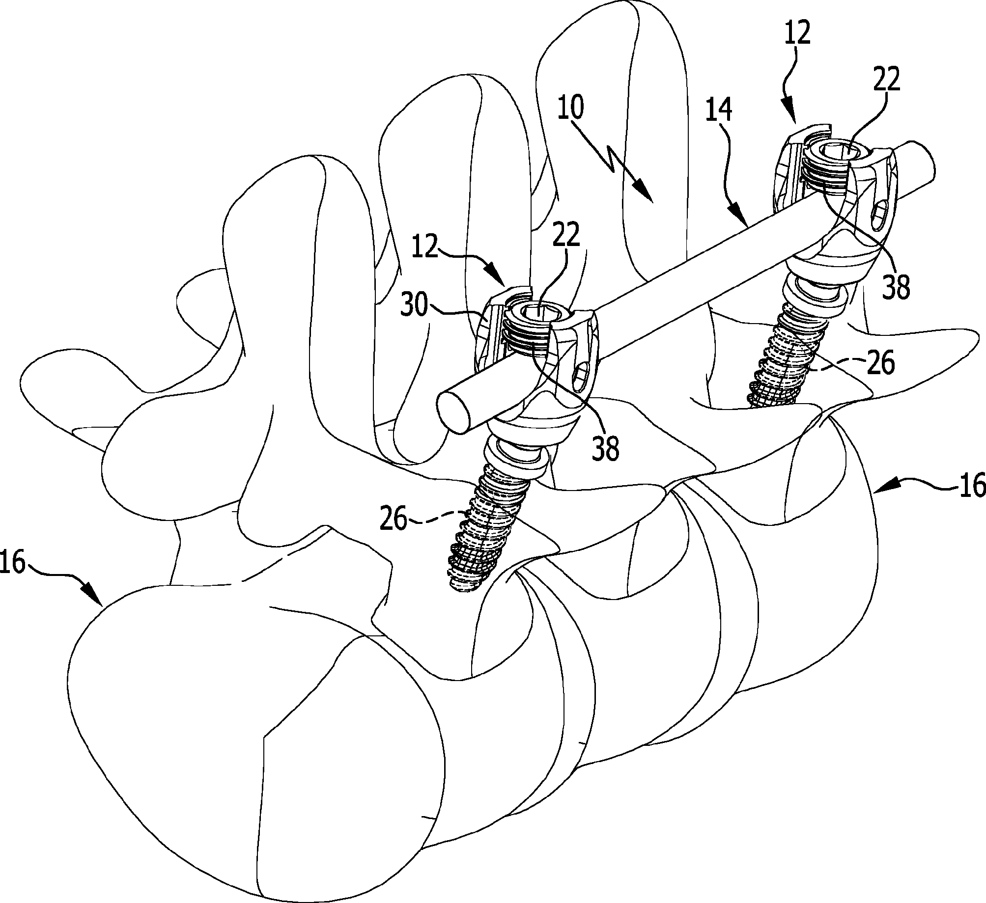
In
Selbstverständlich kann das Wirbelsäulenstabilisierungssystem
In
Bei den Knochenschrauben
Jedes der Pedikelschraubensysteme
An der Verbindungselementaufnahme
Zur Ausbildung eines Kugelgelenks
Am Schraubenkopf
Distalseitig schließt sich an den Gelenkkopf
Das Pedikelschraubensystem
Die Knochenausrichtvorrichtung
Der Kopplungsabschnitt
Ein proximales Ende der Knochenausrichtvorrichtung
Eine Breite des Einführschlitzes
Die Kopplungsreinrichtung
Bei dem in Figuren schematisch dargestellten Ausführungsbeispiel ist das erste Kopplungselement
Der Kopplungsvorsprung
Die Kopplungsaufnahme
Die Kopplungsaufnahme
Der Kopplungsabschnitt
Bei dem in den Figuren dargestellten Ausführungsbeispiel der Knochenausrichtvorrichtung
Die Kopplungseinrichtung
Das Anschlagelement
Das Anschlagelement
Der Ringflansch
Ferner weist der Schraubenkopf
Die Oberseite
Die Führungsfläche
Die Schwenkachse
Die Klemmplatte
Die besondere Ausgestaltung der Knochenausrichtvorrichtung
Zum Einführen des Kopplungsvorsprungs
Die Führungsfläche
Um zu verhindern, dass sich die Knochenausrichtvorrichtung
Die Aufnahme
Die Oberseite
Durch den beschriebenen Satz von Knochenausrichtvorrichtungen
Mit dem Pedikelschraubensystem
Wird wieder die volle Polyaxialität der Pedikelschraube
BezugszeichenlisteLIST OF REFERENCE NUMBERS
- 1010
- Wirbelsäulenstabilisierungssystem Spine stabilization system
- 1212
- Knochenschraube bone screw
- 1414
- Verbindungselement connecting element
- 1616
- Wirbel whirl
- 1818
- Wirbelsäule spinal column
- 2020
- Fixierschraube fixing screw
- 2222
- Pedikelschraubensystem pedicle screw system
- 2424
- Pedikelschraube pedicle screw
- 2626
- Schraubenschaft screw shaft
- 2828
- Außengewinde external thread
- 3030
- Schraubenkopf screw head
- 3232
- Schenkel leg
- 3434
- Verbindungselementaufnahme Connecting element receptacle
- 3636
- Innengewinde inner thread
- 3838
- Außengewinde external thread
- 4040
- Kugelgelenk ball joint
- 4242
- Gelenkkopf joint head
- 4444
- Endfläche end face
- 4646
- Gelenkkopffläche Condyle surface
- 4848
- Werkzeugelementaufnahme Tool element receiver
- 5050
- Gelenkkopfaufnahme Joint head receptacle
- 5252
- Sitz Seat
- 5454
- Durchbrechung perforation
- 5656
- Ende The End
- 5858
- Schaftabschnitt shank portion
- 6060
- Ringflansch annular flange
- 6262
- Knochenausrichtvorrichtung Knochenausrichtvorrichtung
- 6464
- Kopplungseinrichtung coupling device
- 6666
- Klemmplatte clamp
- 6868
- Kopplungsabschnitt coupling portion
- 7070
- Handhabungsabschnitt handling section
- 72 72
- Klemmschenkel clamping leg
- 7474
- Einführschlitz insertion
- 7676
- Griffbereich grip area
- 7878
- Verbindungsplatte connecting plate
- 8080
- Ende The End
- 8282
- Aufgleitfläche sliding surface
- 8484
- erstes Kopplungselement first coupling element
- 8686
- zweites Kopplungselement second coupling element
- 8888
- Kopplungsvorsprung coupling projection
- 9090
- Kopplungsaufnahme female coupling
- 9292
- Durchbrechung perforation
- 9494
- Bohrung drilling
- 9696
- Innendurchmesser Inner diameter
- 9898
- Außendurchmesser outer diameter
- 100100
- Breite width
- 102102
- Kopplungsaufnahmelängsachse Female coupling longitudinal axis
- 104104
- Ebene level
- 106106
- Unterseite bottom
- 108108
- Längsachse longitudinal axis
- 110110
- Längsachse longitudinal axis
- 112112
- Winkel angle
- 114114
- Schraubenschaftaufnahme Screw shaft receiver
- 116116
- Anschlagelement stop element
- 118118
- Anschlagelementanlagefläche Stop element contact surface
- 120120
- Anschlagfläche stop surface
- 122122
- Außendurchmesser outer diameter
- 124124
- Außendurchmesser outer diameter
- 126126
- Anlagefläche contact surface
- 128128
- Oberseite top
- 130130
- Führungsfläche guide surface
- 132132
- Schwenkachse swivel axis
- 134134
- Zylinderoberfläche cylinder surface
- 136136
- Schraubenschaftlängsachse Screw shaft longitudinal axis
- 138138
- Führungskörper guide body
- 140140
- Blockierhülse blocking sleeve
- 142142
- Aufnahme admission
- 144144
- Ende The End
- 146146
- Ausrichtwinkel alignment angle
- 148148
- Längsachse longitudinal axis
ZITATE ENTHALTEN IN DER BESCHREIBUNG QUOTES INCLUDE IN THE DESCRIPTION
Diese Liste der vom Anmelder aufgeführten Dokumente wurde automatisiert erzeugt und ist ausschließlich zur besseren Information des Lesers aufgenommen. Die Liste ist nicht Bestandteil der deutschen Patent- bzw. Gebrauchsmusteranmeldung. Das DPMA übernimmt keinerlei Haftung für etwaige Fehler oder Auslassungen.This list of the documents listed by the applicant has been generated automatically and is included solely for the better information of the reader. The list is not part of the German patent or utility model application. The DPMA assumes no liability for any errors or omissions.
Zitierte PatentliteraturCited patent literature
- DE 102013100574 A1 [0003] DE 102013100574 A1 [0003]
Claims (25)
Priority Applications (4)
| Application Number | Priority Date | Filing Date | Title |
|---|---|---|---|
| DE102014117176.4A DE102014117176A1 (en) | 2014-11-24 | 2014-11-24 | Pedicle screw system and spine stabilization system |
| JP2015227244A JP6706488B2 (en) | 2014-11-24 | 2015-11-20 | Pedicle screw system and spinal cord stabilization system |
| US14/948,905 US9795417B2 (en) | 2014-11-24 | 2015-11-23 | Pedicle screw system and spinal stabilization system |
| EP15195764.4A EP3023065B1 (en) | 2014-11-24 | 2015-11-23 | Pedicle screw system and spinal column-stabilizing system |
Applications Claiming Priority (1)
| Application Number | Priority Date | Filing Date | Title |
|---|---|---|---|
| DE102014117176.4A DE102014117176A1 (en) | 2014-11-24 | 2014-11-24 | Pedicle screw system and spine stabilization system |
Publications (1)
| Publication Number | Publication Date |
|---|---|
| DE102014117176A1 true DE102014117176A1 (en) | 2016-05-25 |
Family
ID=54695610
Family Applications (1)
| Application Number | Title | Priority Date | Filing Date |
|---|---|---|---|
| DE102014117176.4A Withdrawn DE102014117176A1 (en) | 2014-11-24 | 2014-11-24 | Pedicle screw system and spine stabilization system |
Country Status (4)
| Country | Link |
|---|---|
| US (1) | US9795417B2 (en) |
| EP (1) | EP3023065B1 (en) |
| JP (1) | JP6706488B2 (en) |
| DE (1) | DE102014117176A1 (en) |
Families Citing this family (14)
| Publication number | Priority date | Publication date | Assignee | Title |
|---|---|---|---|---|
| DE102015109481A1 (en) * | 2015-06-15 | 2016-12-15 | Aesculap Ag | Pedicle screw with radially offset guide |
| US10278687B2 (en) * | 2015-08-18 | 2019-05-07 | Globus Medical, Inc. | Devices and systems for surgical retraction |
| US9700293B2 (en) * | 2015-08-18 | 2017-07-11 | Globus Medical, Inc. | Devices and systems for surgical retraction |
| WO2018150215A1 (en) * | 2017-02-17 | 2018-08-23 | Warsaw Orthopedic, Inc. | Surgical system and method |
| US10966762B2 (en) | 2017-12-15 | 2021-04-06 | Medos International Sarl | Unilateral implant holders and related methods |
| EP3626189B1 (en) * | 2018-09-21 | 2023-05-24 | Biedermann Technologies GmbH & Co. KG | Instrument for attaching to a bone anchor and instrument for use in distraction and/or retraction, in particular for orthopedic or neurosurgery, more specifically for spinal surgery |
| CN113038894B (en) * | 2018-11-16 | 2024-02-02 | 南十字专利私人有限公司 | pedicle screws |
| USD1004774S1 (en) | 2019-03-21 | 2023-11-14 | Medos International Sarl | Kerrison rod reducer |
| US11291481B2 (en) | 2019-03-21 | 2022-04-05 | Medos International Sarl | Rod reducers and related methods |
| US11291482B2 (en) | 2019-03-21 | 2022-04-05 | Medos International Sarl | Rod reducers and related methods |
| US12318121B2 (en) | 2020-11-09 | 2025-06-03 | Medos International Sàrl | Biplanar forceps reducers and methods of use |
| WO2022125692A1 (en) | 2020-12-09 | 2022-06-16 | Alphatec Spine, Inc. | Surgical retractors |
| JP2024538403A (en) | 2021-11-19 | 2024-10-18 | メドス・インターナショナル・エスエイアールエル | Reduction locking mechanism |
| CN120788482A (en) * | 2025-09-05 | 2025-10-17 | 中国人民解放军总医院第一医学中心 | Intraventricular endoscopy guidance and positioning device |
Citations (2)
| Publication number | Priority date | Publication date | Assignee | Title |
|---|---|---|---|---|
| DE102011053295A1 (en) * | 2011-09-06 | 2013-03-07 | Aesculap Ag | Polyaxial pedicle screw with provisional fixation |
| DE102013100574A1 (en) | 2013-01-21 | 2014-07-24 | Aesculap Ag | Implant system and fastener for an implant system |
Family Cites Families (28)
| Publication number | Priority date | Publication date | Assignee | Title |
|---|---|---|---|---|
| US5020519A (en) * | 1990-12-07 | 1991-06-04 | Zimmer, Inc. | Sagittal approximator |
| DE9202587U1 (en) * | 1992-02-28 | 1992-04-16 | Howmedica GmbH, 2314 Schönkirchen | Repositioning instrument |
| US5364397A (en) * | 1993-06-01 | 1994-11-15 | Zimmer, Inc. | Spinal coupler seater with dual jaws and an independent plunger |
| US7189234B2 (en) * | 1998-10-20 | 2007-03-13 | St. Francis Medical Technologies, Inc. | Interspinous process implant sizer and distractor with a split head and size indicator and method |
| US6551316B1 (en) * | 2001-03-02 | 2003-04-22 | Beere Precision Medical Instruments, Inc. | Selective compression and distraction instrument |
| US6440133B1 (en) * | 2001-07-03 | 2002-08-27 | Sdgi Holdings, Inc. | Rod reducer instruments and methods |
| US6746449B2 (en) * | 2001-09-12 | 2004-06-08 | Spinal Concepts, Inc. | Spinal rod translation instrument |
| FR2830433B1 (en) * | 2001-10-04 | 2005-07-01 | Stryker Spine | ASSEMBLY FOR OSTEOSYNTHESIS OF THE SPINACH COMPRISING AN ANCHORING MEMBER HEAD AND A TOOL FOR HEAD FIXING |
| US6660006B2 (en) * | 2002-04-17 | 2003-12-09 | Stryker Spine | Rod persuader |
| US7278995B2 (en) * | 2002-06-04 | 2007-10-09 | Howmedica Osteonics Corp. | Apparatus for securing a spinal rod system |
| US7004947B2 (en) * | 2002-06-24 | 2006-02-28 | Endius Incorporated | Surgical instrument for moving vertebrae |
| US6648888B1 (en) * | 2002-09-06 | 2003-11-18 | Endius Incorporated | Surgical instrument for moving a vertebra |
| US7988698B2 (en) * | 2003-01-28 | 2011-08-02 | Depuy Spine, Inc. | Spinal rod approximator |
| CN1856277A (en) * | 2003-07-03 | 2006-11-01 | 新特斯有限责任公司 | Top loading spinal fixation device and instruments for loading and handling the same |
| US7625376B2 (en) * | 2005-01-26 | 2009-12-01 | Warsaw Orthopedic, Inc. | Reducing instrument for spinal surgery |
| US7799031B2 (en) * | 2005-02-09 | 2010-09-21 | Warsaw Orthopedic, Inc. | Reducing instrument for spinal surgery |
| US7951172B2 (en) | 2005-03-04 | 2011-05-31 | Depuy Spine Sarl | Constrained motion bone screw assembly |
| US8663292B2 (en) * | 2006-08-22 | 2014-03-04 | DePuy Synthes Products, LLC | Reduction sleeve |
| WO2009085057A2 (en) * | 2007-02-12 | 2009-07-09 | Bishop Randolph C | Spinal stabilization system for the stabilization and fixation of the lumbar spine and method for using same |
| EP2144550B1 (en) * | 2007-04-17 | 2021-05-26 | K2M, Inc. | Retraction device for minimally invasive spinal surgery |
| US8287546B2 (en) * | 2008-07-31 | 2012-10-16 | Zimmer Spine, Inc. | Surgical instrument with integrated compression and distraction mechanisms |
| US8298275B2 (en) * | 2009-10-30 | 2012-10-30 | Warsaw Orthopedic, Inc. | Direct control spinal implant |
| US8419778B2 (en) | 2010-01-15 | 2013-04-16 | Ebi, Llc | Uniplanar bone anchor system |
| US8535318B2 (en) * | 2010-04-23 | 2013-09-17 | DePuy Synthes Products, LLC | Minimally invasive instrument set, devices and related methods |
| EP2604204B1 (en) | 2011-12-13 | 2014-10-01 | Biedermann Technologies GmbH & Co. KG | Monoplanar bone anchoring device with selectable pivot plane |
| US8470009B1 (en) | 2012-03-08 | 2013-06-25 | Warsaw Orthopedic, Inc. | Bone fastener and method of use |
| US9480505B2 (en) * | 2012-08-23 | 2016-11-01 | DePuy Synthes Products, Inc. | Bi-planar persuader |
| US9622794B2 (en) * | 2014-02-24 | 2017-04-18 | Hans Robert Tuten | Polyaxial pedicle screw locking and derotation instrument |
-
2014
- 2014-11-24 DE DE102014117176.4A patent/DE102014117176A1/en not_active Withdrawn
-
2015
- 2015-11-20 JP JP2015227244A patent/JP6706488B2/en active Active
- 2015-11-23 EP EP15195764.4A patent/EP3023065B1/en active Active
- 2015-11-23 US US14/948,905 patent/US9795417B2/en active Active
Patent Citations (2)
| Publication number | Priority date | Publication date | Assignee | Title |
|---|---|---|---|---|
| DE102011053295A1 (en) * | 2011-09-06 | 2013-03-07 | Aesculap Ag | Polyaxial pedicle screw with provisional fixation |
| DE102013100574A1 (en) | 2013-01-21 | 2014-07-24 | Aesculap Ag | Implant system and fastener for an implant system |
Also Published As
| Publication number | Publication date |
|---|---|
| US9795417B2 (en) | 2017-10-24 |
| US20160143668A1 (en) | 2016-05-26 |
| JP2016104131A (en) | 2016-06-09 |
| EP3023065A1 (en) | 2016-05-25 |
| JP6706488B2 (en) | 2020-06-10 |
| EP3023065B1 (en) | 2020-11-04 |
Similar Documents
| Publication | Publication Date | Title |
|---|---|---|
| EP3023065B1 (en) | Pedicle screw system and spinal column-stabilizing system | |
| EP0650344B1 (en) | Osteo-synthetic securing component and manipulation aid therefor | |
| DE69723108T2 (en) | ADJUSTABLE OSTEOSYNTHESIS DEVICE FOR THE SPINE AND POSITIONING TOOL | |
| EP1261288B1 (en) | Connector element for bone rods or spinal rods | |
| DE69905707T2 (en) | SPINE OSTEOSYNTHESIS SYSTEM WITH TENSIONING DEVICE, ESPECIALLY FOR FRONT FIXING | |
| EP1952775B1 (en) | Stabilisation device for dynamic stabilisation of vertebrae | |
| DE69917633T2 (en) | DEVICE FOR SECURING A SPIN BAR | |
| DE69222772T2 (en) | SYSTEM FOR FIXING THE SPINE | |
| EP2452642B1 (en) | Pedicle screw | |
| EP2692304B1 (en) | Set of surgical instruments | |
| EP0948939B1 (en) | Pedicle screw and mounting tool | |
| DE69835355T2 (en) | Multiaxial-BONE SCREW ASSEMBLY | |
| DE69726746T2 (en) | MULTI-AXIS BONE SCREW ARRANGEMENT | |
| DE69431348T2 (en) | SPINAL FASTENING SYSTEM | |
| DE102005009282A1 (en) | Fixing element for a bone implant system comprises a fixing part with a fixing section on the distal side and a receiving part connected to the fixing part | |
| DE102016108504A1 (en) | Medical instrument for temporary fixation of a polyaxial pedicle screw | |
| DE10136162B4 (en) | Connecting element for connecting two used for bone and spine stabilization rod-shaped elements | |
| DE202009018581U1 (en) | Adjustable bar arrangement | |
| DE102015008036A1 (en) | Pedicle screw with tulip | |
| DE4330837A1 (en) | Pedicle screw and internal fixator | |
| WO2002094114A1 (en) | Manipulator for handling a pedicule screw | |
| DE102015120955A1 (en) | Medical instrument and medical instrument | |
| DE102014109935A1 (en) | Positioning device for fixing an intramedullary nail in a long bone | |
| EP3023066B1 (en) | Pedicle screw system and spinal column-stabilizing system | |
| EP4478971A1 (en) | Bone clamp |
Legal Events
| Date | Code | Title | Description |
|---|---|---|---|
| R163 | Identified publications notified | ||
| R082 | Change of representative |
Representative=s name: HOEGER, STELLRECHT & PARTNER PATENTANWAELTE MB, DE |
|
| R082 | Change of representative |
Representative=s name: HOEGER, STELLRECHT & PARTNER PATENTANWAELTE MB, DE |
|
| R005 | Application deemed withdrawn due to failure to request examination |