DE102014112351B4 - SENSOR-ASSISTED VEHICLE POSITIONING SYSTEM - Google Patents
SENSOR-ASSISTED VEHICLE POSITIONING SYSTEM Download PDFInfo
- Publication number
- DE102014112351B4 DE102014112351B4 DE102014112351.4A DE102014112351A DE102014112351B4 DE 102014112351 B4 DE102014112351 B4 DE 102014112351B4 DE 102014112351 A DE102014112351 A DE 102014112351A DE 102014112351 B4 DE102014112351 B4 DE 102014112351B4
- Authority
- DE
- Germany
- Prior art keywords
- vehicle
- road
- objects
- coordinates
- bend
- Prior art date
- Legal status (The legal status is an assumption and is not a legal conclusion. Google has not performed a legal analysis and makes no representation as to the accuracy of the status listed.)
- Active
Links
Images


Classifications
-
- G—PHYSICS
- G01—MEASURING; TESTING
- G01C—MEASURING DISTANCES, LEVELS OR BEARINGS; SURVEYING; NAVIGATION; GYROSCOPIC INSTRUMENTS; PHOTOGRAMMETRY OR VIDEOGRAMMETRY
- G01C21/00—Navigation; Navigational instruments not provided for in groups G01C1/00 - G01C19/00
- G01C21/26—Navigation; Navigational instruments not provided for in groups G01C1/00 - G01C19/00 specially adapted for navigation in a road network
- G01C21/28—Navigation; Navigational instruments not provided for in groups G01C1/00 - G01C19/00 specially adapted for navigation in a road network with correlation of data from several navigational instruments
- G01C21/30—Map- or contour-matching
-
- B—PERFORMING OPERATIONS; TRANSPORTING
- B60—VEHICLES IN GENERAL
- B60W—CONJOINT CONTROL OF VEHICLE SUB-UNITS OF DIFFERENT TYPE OR DIFFERENT FUNCTION; CONTROL SYSTEMS SPECIALLY ADAPTED FOR HYBRID VEHICLES; ROAD VEHICLE DRIVE CONTROL SYSTEMS FOR PURPOSES NOT RELATED TO THE CONTROL OF A PARTICULAR SUB-UNIT
- B60W30/00—Purposes of road vehicle drive control systems not related to the control of a particular sub-unit, e.g. of systems using conjoint control of vehicle sub-units
- B60W30/08—Active safety systems predicting or avoiding probable or impending collision or attempting to minimise its consequences
- B60W30/095—Predicting travel path or likelihood of collision
- B60W30/0956—Predicting travel path or likelihood of collision the prediction being responsive to traffic or environmental parameters
-
- G—PHYSICS
- G01—MEASURING; TESTING
- G01C—MEASURING DISTANCES, LEVELS OR BEARINGS; SURVEYING; NAVIGATION; GYROSCOPIC INSTRUMENTS; PHOTOGRAMMETRY OR VIDEOGRAMMETRY
- G01C21/00—Navigation; Navigational instruments not provided for in groups G01C1/00 - G01C19/00
- G01C21/26—Navigation; Navigational instruments not provided for in groups G01C1/00 - G01C19/00 specially adapted for navigation in a road network
- G01C21/34—Route searching; Route guidance
- G01C21/36—Input/output arrangements for on-board computers
- G01C21/3602—Input other than that of destination using image analysis, e.g. detection of road signs, lanes, buildings, real preceding vehicles using a camera
-
- G—PHYSICS
- G01—MEASURING; TESTING
- G01S—RADIO DIRECTION-FINDING; RADIO NAVIGATION; DETERMINING DISTANCE OR VELOCITY BY USE OF RADIO WAVES; LOCATING OR PRESENCE-DETECTING BY USE OF THE REFLECTION OR RERADIATION OF RADIO WAVES; ANALOGOUS ARRANGEMENTS USING OTHER WAVES
- G01S13/00—Systems using the reflection or reradiation of radio waves, e.g. radar systems; Analogous systems using reflection or reradiation of waves whose nature or wavelength is irrelevant or unspecified
- G01S13/88—Radar or analogous systems specially adapted for specific applications
- G01S13/93—Radar or analogous systems specially adapted for specific applications for anti-collision purposes
- G01S13/931—Radar or analogous systems specially adapted for specific applications for anti-collision purposes of land vehicles
-
- G—PHYSICS
- G01—MEASURING; TESTING
- G01S—RADIO DIRECTION-FINDING; RADIO NAVIGATION; DETERMINING DISTANCE OR VELOCITY BY USE OF RADIO WAVES; LOCATING OR PRESENCE-DETECTING BY USE OF THE REFLECTION OR RERADIATION OF RADIO WAVES; ANALOGOUS ARRANGEMENTS USING OTHER WAVES
- G01S19/00—Satellite radio beacon positioning systems; Determining position, velocity or attitude using signals transmitted by such systems
- G01S19/38—Determining a navigation solution using signals transmitted by a satellite radio beacon positioning system
- G01S19/39—Determining a navigation solution using signals transmitted by a satellite radio beacon positioning system the satellite radio beacon positioning system transmitting time-stamped messages, e.g. GPS [Global Positioning System], GLONASS [Global Orbiting Navigation Satellite System] or GALILEO
- G01S19/42—Determining position
- G01S19/48—Determining position by combining or switching between position solutions derived from the satellite radio beacon positioning system and position solutions derived from a further system
- G01S19/485—Determining position by combining or switching between position solutions derived from the satellite radio beacon positioning system and position solutions derived from a further system whereby the further system is an optical system or imaging system
-
- G—PHYSICS
- G05—CONTROLLING; REGULATING
- G05D—SYSTEMS FOR CONTROLLING OR REGULATING NON-ELECTRIC VARIABLES
- G05D1/00—Control of position, course, altitude or attitude of land, water, air or space vehicles, e.g. using automatic pilots
- G05D1/02—Control of position or course in two dimensions
- G05D1/021—Control of position or course in two dimensions specially adapted to land vehicles
- G05D1/0212—Control of position or course in two dimensions specially adapted to land vehicles with means for defining a desired trajectory
-
- G—PHYSICS
- G01—MEASURING; TESTING
- G01S—RADIO DIRECTION-FINDING; RADIO NAVIGATION; DETERMINING DISTANCE OR VELOCITY BY USE OF RADIO WAVES; LOCATING OR PRESENCE-DETECTING BY USE OF THE REFLECTION OR RERADIATION OF RADIO WAVES; ANALOGOUS ARRANGEMENTS USING OTHER WAVES
- G01S13/00—Systems using the reflection or reradiation of radio waves, e.g. radar systems; Analogous systems using reflection or reradiation of waves whose nature or wavelength is irrelevant or unspecified
- G01S13/02—Systems using reflection of radio waves, e.g. primary radar systems; Analogous systems
- G01S13/06—Systems determining position data of a target
-
- G—PHYSICS
- G01—MEASURING; TESTING
- G01S—RADIO DIRECTION-FINDING; RADIO NAVIGATION; DETERMINING DISTANCE OR VELOCITY BY USE OF RADIO WAVES; LOCATING OR PRESENCE-DETECTING BY USE OF THE REFLECTION OR RERADIATION OF RADIO WAVES; ANALOGOUS ARRANGEMENTS USING OTHER WAVES
- G01S13/00—Systems using the reflection or reradiation of radio waves, e.g. radar systems; Analogous systems using reflection or reradiation of waves whose nature or wavelength is irrelevant or unspecified
- G01S13/88—Radar or analogous systems specially adapted for specific applications
- G01S13/93—Radar or analogous systems specially adapted for specific applications for anti-collision purposes
- G01S13/931—Radar or analogous systems specially adapted for specific applications for anti-collision purposes of land vehicles
- G01S2013/9322—Radar or analogous systems specially adapted for specific applications for anti-collision purposes of land vehicles using additional data, e.g. driver condition, road state or weather data
-
- G—PHYSICS
- G01—MEASURING; TESTING
- G01S—RADIO DIRECTION-FINDING; RADIO NAVIGATION; DETERMINING DISTANCE OR VELOCITY BY USE OF RADIO WAVES; LOCATING OR PRESENCE-DETECTING BY USE OF THE REFLECTION OR RERADIATION OF RADIO WAVES; ANALOGOUS ARRANGEMENTS USING OTHER WAVES
- G01S5/00—Position-fixing by co-ordinating two or more direction or position line determinations; Position-fixing by co-ordinating two or more distance determinations
- G01S5/16—Position-fixing by co-ordinating two or more direction or position line determinations; Position-fixing by co-ordinating two or more distance determinations using electromagnetic waves other than radio waves
-
- G—PHYSICS
- G01—MEASURING; TESTING
- G01S—RADIO DIRECTION-FINDING; RADIO NAVIGATION; DETERMINING DISTANCE OR VELOCITY BY USE OF RADIO WAVES; LOCATING OR PRESENCE-DETECTING BY USE OF THE REFLECTION OR RERADIATION OF RADIO WAVES; ANALOGOUS ARRANGEMENTS USING OTHER WAVES
- G01S7/00—Details of systems according to groups G01S13/00, G01S15/00, G01S17/00
- G01S7/02—Details of systems according to groups G01S13/00, G01S15/00, G01S17/00 of systems according to group G01S13/00
- G01S7/41—Details of systems according to groups G01S13/00, G01S15/00, G01S17/00 of systems according to group G01S13/00 using analysis of echo signal for target characterisation; Target signature; Target cross-section
- G01S7/411—Identification of targets based on measurements of radar reflectivity
- G01S7/412—Identification of targets based on measurements of radar reflectivity based on a comparison between measured values and known or stored values
Landscapes
- Engineering & Computer Science (AREA)
- Radar, Positioning & Navigation (AREA)
- Remote Sensing (AREA)
- Physics & Mathematics (AREA)
- General Physics & Mathematics (AREA)
- Automation & Control Theory (AREA)
- Computer Networks & Wireless Communication (AREA)
- Computer Vision & Pattern Recognition (AREA)
- Transportation (AREA)
- Mechanical Engineering (AREA)
- Electromagnetism (AREA)
- Aviation & Aerospace Engineering (AREA)
- Navigation (AREA)
- Position Fixing By Use Of Radio Waves (AREA)
- Traffic Control Systems (AREA)
Abstract
Sensorgestütztes Fahrzeugpositionsbestimmungssystem, umfassend:
eine GPS-basierte Vorrichtung, die GPS-Koordinaten eines Fahrzeugs auf einer gefahrenen Straße erzeugt;
eine Datenbank (20), die digitale Landkartendaten enthält, die verwendet werden, um beruhend auf dem Ort der GPS-Koordinaten eine digitale Landkarte einer Region zu erzeugen, die von dem Fahrzeug befahren wird, wobei die digitale Landkarte eine geographische Abbildung einer befahrenen Straße und von registrierten Objekten am Straßenrand umfasst, wobei die registrierten Objekte am Straßenrand in der digitalen Landkarte durch Längengrad- und Breitengradkoordinaten positionstechnisch identifiziert sind;
eine Objektdetektionsvorrichtung, die Objekte am Straßenrand in der Region erfasst, die von dem Fahrzeug befahren wird, wobei die erfassten Objekte am Straßenrand auf der digitalen Landkarte identifiziert werden; und
eine Verarbeitungseinheit (10), die eine Fahrzeugposition auf der gefahrenen Straße unter Verwendung von Koordinaten der erfassten Objekte am Straßenrand, die in der digitalen Landkarte identifiziert wurden, bestimmt, wobei die Verarbeitungseinheit (10) die Position des Fahrzeugs auf der Fahrstraße als Funktion der GPS-Koordinaten und der bestimmten Fahrzeugposition unter Verwendung der Koordinaten der erfassten Objekte am Straßenrand lokalisiert,
dadurch gekennzeichnet, dass das Lokalisieren der Position des Fahrzeugs auf der Fahrstraße ferner eine Funktion des Identifizierens einer Stra-ßenkrümmung und des Bestimmens einer Fahrzeugposition auf der Grundlage eines Orts des Fahrzeugs in der Krümmung ist, wobei die Krümmungsformel repräsentiert wird als:
![]()
wobei s die Position des Fahrzeugs ist und K die Krümmung der Straße ist.

a GPS-based device that generates GPS coordinates of a vehicle on a driven road;
a database (20) containing digital map data used to generate a digital map of a region traveled by the vehicle based on the location of the GPS coordinates, the digital map being a geographical image of a traveled road and of registered objects on the side of the road, the registered objects on the side of the road being identified in terms of position in the digital map by longitude and latitude coordinates;
an object detection device that detects roadside objects in the region traveled by the vehicle, identifying the detected roadside objects on the digital map; and
a processing unit (10) which determines a vehicle position on the driven road using coordinates of the detected roadside objects identified in the digital map, the processing unit (10) determining the position of the vehicle on the travel road as a function of the GPS -Coordinates and the specific vehicle position localized using the coordinates of the detected objects on the side of the road,
characterized in that locating the position of the vehicle on the roadway is further a function of identifying a road curvature and determining a vehicle position based on a location of the vehicle on the curvature, the curvature formula being represented as:![]()
where s is the position of the vehicle and K is the curvature of the road.
Description
HINTERGRUND DER ERFINDUNGBACKGROUND OF THE INVENTION
Eine Ausführungsform betrifft allgemein Fahrzeugpositionsbestimmungssysteme.One embodiment relates generally to vehicle positioning systems.
Empfänger eines globalen Positionsbestimmungssystems (GPS) oder eines anderen globalen Satellitennavigationssystems (GNSS) arbeiten, indem sie Sichtverbindungssignale verfolgen. Diese Empfänger erfordern typischerweise, dass mindestens vier oder mehr Satelliten in einer nicht beeinträchtigten Sichtverbindung zu einem Satellitenempfänger in einem Fahrzeug kontinuierlich zur Verfügung stehen. Aufgrund von natürlichen und menschengemachten Hindernissen (z.B. Gebäuden) oder natürlichen Hindernissen (d.h. eine dichte Abdeckung durch Bäume) kann es sein, dass unter bestimmten Bedingungen die theoretische Minimalzahl der Satelliten, die zur genauen Bestimmung einer Position des Satellitenempfängers benötigt werden, nicht verfügbar ist. Es ist gut bekannt, dass GPS-Positionsfehler bis zu 30 Meter betragen können. Während derartige Fehler zu kleineren Unannehmlichkeiten bei der Navigation dahingehend führen können, ob sich das Fahrzeug exakt an einer Stelle befindet (z.B. einer Kreuzung), gibt es größere Probleme, wenn Systeme etwa zur Fahrspurzentrierung oder Geschwindigkeitsregelung verwendet werden, wenn das Fahrzeug gerade einen kurvigen Abschnitt der Straße durchfährt. Wenn ein automatisiertes Fahrzeugsystem die Geschwindigkeit oder die Spurzentrierung des Fahrzeugs steuert und sich das System auf die Position von der GPS-Position des Fahrzeugs verlässt, dann kann die Einschätzung, dass sich das Fahrzeug auf einem linearen Abschnitt der Straße befindet, statt auf einem kurvigen Abschnitt der Straße, negative Konsequenzen haben.Global positioning system (GPS) or other global navigation satellite system (GNSS) receivers work by tracking line-of-sight signals. These receivers typically require that at least four or more satellites be continuously available in unobstructed line of sight to a satellite receiver in a vehicle. Due to natural and man-made obstacles (e.g. buildings) or natural obstructions (i.e. dense tree cover), under certain conditions the theoretical minimum number of satellites needed to accurately determine a satellite receiver position may not be available. It is well known that GPS position errors can be up to 30 meters. While such errors can cause minor inconveniences when navigating whether the vehicle is in an exact location (e.g. an intersection), there are major problems when using systems such as lane centering or cruise control when the vehicle is about to navigate a curved section the road passes through. If an automated vehicle system controls the vehicle's speed or lane centering and the system relies on the position from the vehicle's GPS location, then the assessment can be that the vehicle is on a linear portion of the road rather than a curved portion the road, have negative consequences.
Die Druckschrift
ZUSAMMENFASSUNG DER ERFINDUNGSUMMARY OF THE INVENTION
Ein Vorteil einer Ausführungsform besteht in der Detektion von Objekten in einer Umgebung einer Fahrstraße durch Objektdetektionsvorrichtungen des Fahrzeugs zum Vergleichen mit einer digitalen Landkarte, um alle Positionsfehler in der ermittelten GPS-Position zu korrigieren. Zudem können andere Signale von anderen Vorrichtungen wie etwa WiFi, RFID-Markern und Pseudoliten bzw. Pseudo-Satelliten einzeln oder in Zusammenarbeit miteinander verwendet werden, um eine Fahrzeugposition auf der Straße zu identifizieren, die verwendet wird, um alle GPS-Positionsfehler zu korrigieren.An advantage of an embodiment is the detection of objects in a surroundings of a roadway by object detection devices of the vehicle for comparison with a digital map in order to correct any position errors in the determined GPS position. Additionally, other signals from other devices such as WiFi, RFID markers and pseudolites or pseudo-satellites can be used individually or in cooperation with one another to identify a vehicle position on the road, which is used to correct any GPS position errors.
Ein Verfahren zum Lokalisieren eines Fahrzeugs in einer digitalen Landkarte umfasst, dass GPS-Koordinaten des Fahrzeugs auf der gefahrenen Straße erzeugt werden. Aus einer Datenbank wird eine digitale Landkarte einer Region geholt, die von dem Fahrzeug befahren wird, beruhend auf dem Ort der GPS-Koordinaten. Die digitale Landkarte enthält eine geographische Abbildung einer gefahrenen Straße und von registrierten Objekten am Straßenrand. Die registrierten Objekte am Straßenrand sind in der digitalen Landkarte durch Längengrad- und Breitengrad-Koordinaten positionstechnisch identifiziert. Objekte am Straßenrand in der Region, die von dem Fahrzeug befahren wird, werden erfasst. Die erfassten Objekte am Rand auf der digitalen Landkarte werden identifiziert. Eine Fahrzeugposition auf der gefahrenen Straße wird unter Verwendung von Koordinaten der erfassten Objekte am Straßenrand, die in der digitalen Landkarte identifiziert wurden, bestimmt. Die Position des Fahrzeugs auf der Fahrstraße wird als Funktion der GPS-Koordinaten und der unter Verwendung der Koordinaten der erfassten Objekte am Straßenrand bestimmten Fahrzeugposition lokalisiert.A method for locating a vehicle on a digital map includes generating GPS coordinates of the vehicle on the road being driven. A digital map of a region traveled by the vehicle is retrieved from a database based on the location of the GPS coordinates. The digital map contains a geographical image of a driven road and registered objects on the side of the road. The registered objects on the side of the road are identified in terms of position in the digital map using longitude and latitude coordinates. Objects on the side of the road in the region the vehicle is traveling through are detected. The recorded objects at the edge of the digital map are identified. A vehicle position on the traveled road is determined using coordinates of the detected roadside objects identified in the digital map. The position of the vehicle on the roadway is located as a function of the GPS coordinates and the vehicle position determined using the coordinates of the detected roadside objects.
Ein sensorgestütztes Fahrzeugpositionsbestimmungssystem umfasst eine GPS-basierte Vorrichtung, die GPS-Koordinaten eines Fahrzeugs auf einer gefahrenen Straße erzeugt. Eine Datenbank enthält digitale Landkartendaten, die verwendet werden, um eine digitale Landkarte einer Region, die von dem Fahrzeug befahren wird, beruhend auf dem Ort der GPS-Koordinaten zu erzeugen. Die digitale Landkarte umfasst eine geographische Abbildung einer gefahrenen Straße und registrierte Objekte am Straßenrand. Die registrierten Objekte am Straßenrand sind in der digitalen Landkarte durch Längengrad- und Breitengrad-Koordinaten positionstechnisch identifiziert. Eine Objektdetektionsvorrichtung erfasst Objekte am Straßenrand in der Region, die von dem Fahrzeug befahren wird. Die erfassten Objekte am Straßenrand werden auf der digitalen Landkarte identifiziert. Eine Verarbeitungseinheit bestimmt eine Fahrzeugposition auf der gefahrenen Straße unter Verwendung von Koordinaten der erfassten Objekte am Straßenrand, die in der digitalen Landkarte identifiziert wurden. Die Verarbeitungseinheit lokalisiert die Position des Fahrzeugs auf der Fahrstraße als Funktion der GPS-Koordinaten und der unter Verwendung der Koordinaten der erfassten Objekte am Straßenrand bestimmten Fahrzeugposition.A sensor-based vehicle positioning system includes a GPS-based device that generates GPS coordinates of a vehicle on a driven road. A database contains digital map data that is used to generate a digital map of a region traveled by the vehicle based on the location of the GPS coordinates. The digital map includes a geographical image of a driven road and registered objects on the side of the road. The registered objects on the side of the road are identified in terms of position in the digital map using longitude and latitude coordinates. An object detection device detects objects on the side of the road in the region traveled by the vehicle. The recorded objects on the side of the road are identified on the digital map. A processing unit determines a vehicle position on the driven road using coordinates of the detected roadside objects identified in the digital map. The processing unit locates the position of the vehicle on the road road as a function of the GPS coordinates and the vehicle position determined using the coordinates of the detected objects on the side of the road.
KURZBESCHREIBUNG DER ZEICHNUNGENBRIEF DESCRIPTION OF DRAWINGS
-
1 ist ein sensorgestütztes Fahrzeugpositionsbestimmungssystem.1 is a sensor-based vehicle positioning system. -
2 ist eine bildliche Darstellung eines Positionsfehlers, der bei einer GPS-Position auftritt.2 is a pictorial representation of a position error that occurs in a GPS position. -
3 ist eine bildliche Darstellung von externen Objekten, die von dem Fahrzeug zur Fahrzeugpositionsbestimmung erfasst werden.3 is a pictorial representation of external objects detected by the vehicle to determine vehicle position. -
4a veranschaulicht eine Straßenkurve, die durch einen Kreisbogen dargestellt ist.4a illustrates a road curve represented by a circular arc. -
4b veranschaulicht eine graphische Darstellung zum Identifizieren einer Position beruhend auf einer Funktion zur Fahrtrichtungsmessung.4b illustrates a graphical representation for identifying a position based on a heading measurement function. -
5a veranschaulicht ein Fahrzeug, das einen kurvigen Abschnitt einer Straße durchquert.5a illustrates a vehicle traversing a curved section of a road. -
5b veranschaulicht eine graphische Darstellung zur Bestimmung einer Fahrzeugposition beruhend auf einer bekannten Biegung einer Straße.5b illustrates a graphical representation for determining a vehicle position based on a known bend in a road. -
6 ist eine bildliche Darstellung eines Fahrzeugs mit einer GPS-Signalblockade.6 is a pictorial representation of a vehicle with a GPS signal blockage. -
7 veranschaulicht ein Flussdiagramm zur Korrektur von GPS-Fehlern und Verwendung von erfassten Objekten am Stra-ßenrand.7 illustrates a flowchart for correcting GPS errors and using detected roadside objects.
GENAUE BESCHREIBUNGPRECISE DESCRIPTION
In
Das Fahrzeug erhält eine globale Position unter Verwendung eines Fahrzeugpositionsbestimmungssystems. Das Fahrzeugpositionsbestimmungssystem umfasst einen Empfänger für ein fahrzeugeigenes globales Satellitennavigationssystem (GNSS) oder einen Empfänger 18 für ein anderes globales Positionsbestimmungssystem (GPS). Es versteht sich, dass die Begriffe GNSS und GPS hier austauschbar verwendet werden. Ein GNSS-System umfasst eine Konstellation aus Satelliten zur globalen Positionsbestimmung, die mindestens 24 oder mehr Satelliten enthält, welche die Erde in einer vorbestimmten Fahrstrecke umkreisen, wobei sie kontinuierlich Datensignale mit Zeitmarkierungen senden. Ein GNSS-Empfänger arbeitet, indem er Sichtverbindungssignale verfolgt. Diese Empfänger benötigen typischerweise mindestens vier oder mehr Satelliten, die in einer unbehinderten Sichtverbindung mit einem Satellitenempfänger in einem Fahrzeug kontinuierlich verfügbar sind. Der GNSS-Empfänger empfängt die gesendeten Daten und verwendet diese Informationen, um seine Absolutposition zu bestimmen. Bei der Betrachtung der Erde in einer zweidimensionalen Ebene wird jeder Punkt auf der Erde durch zwei Koordinaten identifiziert. Die erste Koordinate repräsentiert einen Breitengrad und die zweite Koordinate repräsentiert einen Längengrad in der zweidimensionalen Ebene, wobei mindestens drei Satelliten benötigt werden, da es drei Unbekannte gibt, zwei Unbekannte der Position und den Empfänger-Taktzeitfehler, der auch wie eine Unbekannte behandelt wird. Einige Empfänger können annehmen, dass die Höhe eine kurze Zeitspanne lang gleich bleibt, sodass die Position mit nur drei Satelliten bestimmt werden kann; wenn jedoch die Höhe in Betracht gezogen wird, was bei den meisten Anwendungen der Fall ist, dann werden mindestens vier Satelliten benötigt, um eine Absolutposition mit einem bestimmten Fehlerbetrag zu schätzen.The vehicle obtains a global position using a vehicle positioning system. The vehicle positioning system includes a receiver for a vehicle-based global navigation satellite system (GNSS) or a
Satellitenempfänger arbeiten, indem sie Sichtverbindungssignale verfolgen, was erfordert, dass sich jeder der Satelliten in Sicht des Empfängers befindet. Entwurfsbedingt stellen GNSS oder andere GPS-Systeme sicher, dass sich im Mittel vier oder mehr Satelliten kontinuierlich in der Sichtverbindung eines jeweiligen Empfängers auf der Erde befinden; aufgrund von städtischen Schluchten (d.h. Hindernisse wie etwa Gebäude) oder dem Fahren neben einem Lastwagen jedoch, kann sich eine geringere Anzahl von Satelliten in Sichtverbindung befinden und umso mehr können Hindernisse zu einer geringeren Anzahl von Satelliten führen, als derjenigen, die benötigt wird, um die Position des Satellitenempfängers genau zu bestimmen.Satellite receivers work by tracking line-of-sight signals, which requires each of the satellites to be within view of the receiver. By design, GNSS or other GPS systems ensure that, on average, four or more satellites are continuously within line of sight of a respective receiver on Earth; However, due to urban canyons (i.e. obstacles such as buildings) or driving next to a truck, a smaller number of satellites may be in line of sight and even more so, obstacles may result in a smaller number of satellites than what is needed to to accurately determine the position of the satellite receiver.
Globale Positionsbestimmungssysteme, die der Öffentlichkeit zur öffentlichen Verwendung zur Verfügung gestellt wurden, können in einer städtischen Umgebung eine GPS-Auflösung/Genauigkeit von 30 m aufweisen. Daher kann der Fahrzeugaufenthaltsort in der Navigationslandkarte einen Fehler von 30 m aufweisen. Obwohl der Fahrzeugpositionsfehler möglicherweise keine so große Auswirkung aufweist, wenn das Fahrzeug gerade auf einer geraden Linie fährt, werden diese Positionsfehler wichtiger, wenn das Fahrzeug gerade entlang einer kurvigen Straße fährt. Diese Positionsfehler beim Fahren entlang einer kurvigen Straße werden Fehler bei der Kurvengeschwindigkeitssteuerung sowie der Spurzentrierungssteuerung verursachen.Global positioning systems made available to the public for public use can have a GPS resolution/accuracy of 30 m in an urban environment. Therefore, the vehicle location in the navigation map may have an error of 30 m. Although the vehicle position error may not have as much impact when the vehicle is traveling straight along a straight line, these position errors become more important when the vehicle is traveling straight along a curved road. These position errors when driving along a curved road will cause errors in cornering speed control as well as lane centering control.
Wieder mit Bezug auf
Andere Arten von Signalen, die verwendet werden können, umfassen Pseudolit-Signale 28. Pseudolit-Signale 28 bezeichnen Signale, die nicht von einem Satelliten stammen, aber eine Funktion im Bereich von Satelliten ausführen. Pseudoliten sind typischerweise kleine Sender/Empfänger, die verwendet werden, um eine bodenbasierte GPS-Alternative zur GPS-Positionsbestimmung zu schaffen. Die Reichweite des Signals jedes Senders/Empfängers hängt von der verfügbaren Leistung ab. Wenn Satellitensignale daher blockiert sind, dann können Pseudolit-Signale als Alternative zur Bestimmung der Fahrzeugposition und zum Verringern des GPS-Positionsfehlers verwendet werden.Other types of signals that can be used include pseudolite signals 28. Pseudolite signals 28 refer to signals that do not originate from a satellite but perform a function in the satellite range. Pseudolites are typically small transmitter/receivers used to create a ground-based GPS alternative to GPS positioning. The range of each transmitter/receiver's signal depends on the power available. Therefore, if satellite signals are blocked, then pseudolite signals can be used as an alternative to determine vehicle position and reduce GPS position error.
Analog kann eine Fahrzeugpositionsbestimmung mithilfe von WiFi-Routern 30 oder RFED-Markern 32 bestimmt werden. Die WiFi-Router 30 und die RFID-Marker 32 weisen eine festgelegte Position auf. Daher können gemessene Lage- und Distanzdaten von dem Fahrzeug zu dem WiFi-Router 30 oder den RFID-Markern 32 verwendet werden, um die Fahrzeugposition zu bestimmen, um den GPS-Positionsfehler zu verringern.Analogously, vehicle positioning can be determined using
Das System umfasst ferner eine Biegungsschätzvorrichtung 34 zum Bestimmen einer Biegung der Straße beruhend auf den Eingabedaten, die an den Prozessor 10 geliefert werden. Die Qualität der Biegung der Straße, die von der Biegungsschätzvorrichtung 34 bestimmt wurde, beeinflusst direkt das Verhalten von Ausgabevorrichtungen wie etwa Kurvengeschwindigkeitssteuerungssystemen und Spurzentrierungssteuerungssystemen. Daher kann die Biegung berechnet werden, indem das Straßenprofil in der digitalen Landkarte mit dem GPS-Aufenthaltsort des Fahrzeugs zusammen mit beliebigen Signaleingabedaten von den Objektdetektionsvorrichtungen oder anderen Vorrichtungen, die bei der Bestimmung der Fahrzeugposition helfen, abgeglichen wird.The system further includes a
Ausgabevorrichtungen 36, etwa eine Spurzentrierungssteuerungsvorrichtung zum Zentrieren des Fahrzeugs in einer Fahrspur der Straße oder Kurvengeschwindigkeitssteuerungsvorrichtungen zum Steuern der Geschwindigkeit eines Fahrzeugs in eine Kurve hinein, durch eine Kurve hindurch und aus einer Kurve heraus verwenden die justierten Positionsdaten, die von dem Prozessor 10 bestimmt wurden. Die hier beschriebenen Ausgabevorrichtungen 36 sind nur Beispiele für die verschiedenen Vorrichtungen, die die korrigierten GPS-Positionsdaten verwenden können, die von dem Prozessor ausgegeben werden.
Für diejenigen Objekte, die stationäre Objekte sind, wird angenommen, dass diese punktstationären Objekte (z.B. Baumstamm, Lichtmasten, Verkehrszeichen, WiFi-Zugangspunkte, aktive Marker wie etwa RFIDs und Überkopf-GNSS-Satelliten) und linienstationäre Objekte (z.B. Spurmarkierungen und Leitplanken) in einem feststehenden bekannten lokalen Koordinatensystem (O-xyz) repräsentiert sind. Eines der Beispiele für das lokale Koordinatensystem ist ein Ost-Nord-Nach-Oben-System, bei dem der Ursprung als eine bekannte Koordinate im World Geodetic System (WGS84) ausgedrückt ist. Zur Vereinfachung der Formulierung wird angenommen, dass das Fahrzeug auf einer Bodenebene gefahren wird, die ausgedrückt wird als (z = 0). Die Aufgabe besteht darin, die Fahrzeugposition (x, y), Orientierung (φ) und Längsgeschwindigkeit (vh) auf der Bodenebene herauszufinden. Die Schritte sind wie folgt:
- Zunächst sei die Position der Satelliten S1, S2 und S3 ausgedrückt durch P1, P2 bzw. P3, und die Geschwindigkeit der Satelliten sei ausgedrückt durch V1, V2 bzw. V3. Es sei PH = (x, y, 0)T die Position des Trägerfahrzeugs und VH = (Vhcosφ, Vhsinφ, 0), wobei x, y und φ die Position bzw. die Fahrtrichtung des Fahrzeugs sind und Vh die Längsgeschwindigkeit des Fahrzeugs bezeichnet.
- First, let the position of the satellites S 1 , S 2 and S 3 be expressed by P 1 , P 2 and P 3 , respectively, and the speed of the satellites be expressed by V 1 , V 2 and V 3 , respectively. Let P H = (x, y, 0) T be the position of the carrier vehicle and V H = ( Vh cosφ, V h sinφ, 0), where x, y and φ are the position and direction of travel of the vehicle, respectively, and V h denotes the longitudinal speed of the vehicle.
Die Entfernungsmesswerte zu den Satelliten S1, S2 und S3 sind wie folgt:![]()
![]()
![]()
![]()
![]()
![]()
Die Doppler-Messwerte von den Satelliten S1, S2 und S3 sind wie folgt:![]()
![]()
![]()
![]()
![]()
![]()
![]()
![]()
Als Nächstes wird angenommen, dass die Position des WiFi-Zugangspunkts (AP) als PWIFI bekannt ist und die Position eines Radiofrequenzidentifikationsmarkers (RFID-Markers) als PRFID bekannt ist. Die Distanz zwischen dem Fahrzeug und dem WiFi-AP kann aus der empfangenen Signalstärke hergeleitet werden, die als RWIFI bezeichnet wird. Analog wird die Distanz zwischen dem Fahrzeug und dem RFID als RRFID gemessen. Das Ergebnis sind zwei zusätzliche Messgleichungen: ![]()
![]()
![]()
![]()
Nach dem Linearisieren der zwei zusätzlichen Messgleichungen ist die Minimierungsdarstellung wie folgt:![]()
![]()
Als Nächstes sei die Position des Baumstamms, des Lichtmasts und des Verkehrszeichens beschrieben durch PT = (x1, y1), PL = (x2, y2) und Ps = (x3, y3). Die Sensormessung (Radar oder Lidar) kann wie folgt ausgedrückt werden:![]()
![]()
![]()
![]()
![]()
![]()
![]()
![]()
![]()
![]()
![]()
![]()
![]()
![]()
Schließlich wird angenommen, dass eine Spurmarkierung in einer Linie mit dem Orientierungswinkel η und der Distanz d ausgedrückt wird. Das Ergebnis ist (ηL, DL) für die linke Spurmarkierung, (ηR, DR) für die rechte Spurmarkierung und (ηG, DG) für die Leitplanke. Daher sind die Winkelmessungsgleichungen wie folgt:![]()
![]()
![]()
![]()
![]()
![]()
![]()
![]()
![]()
![]()
![]()
![]()
Daher wird die Minimierungsformel wie folgt dargestellt:![]()
![]()
Zusammengefasst kann die Fahrzeugposition und -orientierung gelöst werden, indem die folgende Gleichung minimiert wird: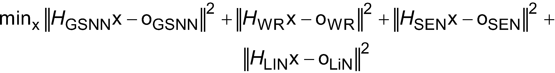

![]()
![]()
Das vorstehende Problem der kleinsten Quadrate kann durch eine QR-Zerlegung unter Verwendung der folgenden Schritte gelöst werden:
- 1) Berechne die QR-Zerlegung der vergrößerten Matrix [A o] = QR
- 2)


- 1) Calculate the QR decomposition of the enlarged matrix [A o] = QR
- 2)
Dabei ist die Fahrzeugposition x = R4 -1z und die entsprechende Kovarianzmatrix Σ = R4 -1R4 -T.The vehicle position is x = R 4 -1 z and the corresponding covariance matrix Σ = R 4 -1 R 4 -T .
Eine andere Technik zur Bestimmung der Position des Fahrzeugs unter Verwendung der GPS-Fahrtrichtung und der Landkartenbiegung ist in ![]()
![]()
![]()
![]()
Bei Schritt 52 wird eine Relativposition von Objekten am Straßenrand (z.B. von Lichtmasten, Brücken, Leitplanken) unter Verwendung von Objektdetektionsvorrichtungen beschafft.At
Bei Schritt 54 werden Straßenbiegungsinformationen relativ zu einer Position von Objekten am Straßenrand (z.B. einem Verkehrszeichen) von Objektdetektionsvorrichtungen erhalten, etwa einer nach vorne blickenden Fahrzeugbildgebungsvorrichtung.At
Bei Schritt 56 werden registrierte Objektdaten in digitalen Landkarten aus einer Datenbank erhalten. Diese umfassen Informationen, welche Koordinaten für jedes der registrierten Objekte innerhalb der digitalen Landkarte der Umgebung der befahrenen Straße umfassen.At
Bei Schritt 58 wird ein Verarbeitungsmodul bereitgestellt, um Eingabedaten von jeder der Vorrichtungen zu empfangen, die in den Blöcken 50-56 beschrieben wurden. Die Verarbeitungseinheit verwendet die verschiedenen Daten, um Positionsfehler in den GPS-Daten zu bestimmen.At
Bei Schritt 60 werden GPS/Trägheits-/Tachometer-Positionsbestimmungsinformationen in ein GPS-basiertes Landkartenabgleichsmodul bei Schritt 62 eingegeben. Zudem werden die Daten, die von dem Verarbeitungsmodul bei Schritt 56 gesammelt wurden, für das GPS-basierte Landkartenabgleichsmodul bereitgestellt. Die Daten von den Schritten 60 und 62 werden abgeglichen, um festzustellen, ob die Eingabedaten übereinstimmen.At
Bei Schritt 64 werden die Ergebnisse von dem GPS-basierten Landkartenabgleichsmodul auf das ADASIS-Horizontprotokoll angewendet. ADASIS ist ein Protokoll, das ein standardisiertes Datenmodell und eine Struktur definiert, um Landkartendaten in der Umgebung der Fahrzeugposition darzustellen. Die ADASIS-Horizontdaten werden dann in Schritt 58 zurück in das Verarbeitungsmodul eingegeben, wobei die hier beschriebenen Positionsbestimmungstechniken auf die Landkartendaten angewendet werden, um Fehler aus den Daten zu entfernen.At
Bei Schritt 66 werden Fahrtrichtungs-, Biegungs- und Positionsinformationen an mindestens eine Ausgabevorrichtung ausgegeben. Die Ausgabevorrichtung kann eine Biegungsgeschwindigkeitssteuerung zum Steuern der Geschwindigkeit durch einen kurvigen Abschnitt der Straße, eine Spurzentrierungssteuerung zum Halten der Position des Fahrzeugs in der Mitte der Spur, speziell wenn in dem kurvigen Abschnitt der Straße gefahren wird, umfassen.At
Claims (10)
Applications Claiming Priority (2)
| Application Number | Priority Date | Filing Date | Title |
|---|---|---|---|
| US14/028,709 | 2013-09-17 | ||
| US14/028,709 US9435653B2 (en) | 2013-09-17 | 2013-09-17 | Sensor-aided vehicle positioning system |
Publications (2)
| Publication Number | Publication Date |
|---|---|
| DE102014112351A1 DE102014112351A1 (en) | 2015-03-19 |
| DE102014112351B4 true DE102014112351B4 (en) | 2023-12-07 |
Family
ID=52580086
Family Applications (1)
| Application Number | Title | Priority Date | Filing Date |
|---|---|---|---|
| DE102014112351.4A Active DE102014112351B4 (en) | 2013-09-17 | 2014-08-28 | SENSOR-ASSISTED VEHICLE POSITIONING SYSTEM |
Country Status (2)
| Country | Link |
|---|---|
| US (2) | US9435653B2 (en) |
| DE (1) | DE102014112351B4 (en) |
Families Citing this family (64)
| Publication number | Priority date | Publication date | Assignee | Title |
|---|---|---|---|---|
| JP6252252B2 (en) * | 2014-02-28 | 2017-12-27 | 株式会社デンソー | Automatic driving device |
| DE102015206342A1 (en) * | 2014-04-09 | 2015-10-15 | Continental Teves Ag & Co. Ohg | Position correction of a vehicle by referencing objects in the environment |
| CN107076838B (en) | 2014-08-15 | 2021-11-05 | 艾耶股份有限公司 | Method and system for lidar transmission |
| EP3032221B1 (en) * | 2014-12-09 | 2022-03-30 | Volvo Car Corporation | Method and system for improving accuracy of digital map data utilized by a vehicle |
| DE102015001386A1 (en) * | 2015-02-04 | 2016-08-04 | Audi Ag | Method for determining a transverse position information of a motor vehicle on a roadway and motor vehicle |
| CA3067160A1 (en) | 2015-02-10 | 2016-08-18 | Mobileye Vision Technologies Ltd. | Sparse map for autonomous vehicle navigation |
| WO2017017705A1 (en) * | 2015-07-24 | 2017-02-02 | 日産自動車株式会社 | Host-position estimation device and host-position estimation method |
| US9857181B2 (en) | 2015-08-11 | 2018-01-02 | Gm Global Technology Operations Llc. | Methods and apparatus for evaluating operation of a vehicle onboard navigation system using lateral offset data |
| US9952049B2 (en) | 2015-09-10 | 2018-04-24 | GM Global Technology Operations LLC | Methods and apparatus for performance assessment of a vehicle onboard navigation system using adaptive stochastic filtering |
| US10082797B2 (en) * | 2015-09-16 | 2018-09-25 | Ford Global Technologies, Llc | Vehicle radar perception and localization |
| DE102015220695A1 (en) * | 2015-10-22 | 2017-04-27 | Robert Bosch Gmbh | Method and device for evaluating the content of a map |
| JPWO2017109978A1 (en) * | 2015-12-25 | 2018-10-18 | パイオニア株式会社 | Distance estimation device, distance estimation method and program |
| US10908262B2 (en) | 2016-02-18 | 2021-02-02 | Aeye, Inc. | Ladar transmitter with optical field splitter/inverter for improved gaze on scan area portions |
| US10042159B2 (en) | 2016-02-18 | 2018-08-07 | Aeye, Inc. | Ladar transmitter with optical field splitter/inverter |
| US10761196B2 (en) | 2016-02-18 | 2020-09-01 | Aeye, Inc. | Adaptive ladar receiving method |
| US9933513B2 (en) | 2016-02-18 | 2018-04-03 | Aeye, Inc. | Method and apparatus for an adaptive ladar receiver |
| WO2017148851A1 (en) * | 2016-03-01 | 2017-09-08 | Bayerische Motoren Werke Aktiengesellschaft | Method for precisely determining the location of a motor vehicle |
| US10248871B2 (en) * | 2016-03-24 | 2019-04-02 | Qualcomm Incorporated | Autonomous lane detection |
| US10234568B2 (en) * | 2016-05-12 | 2019-03-19 | GM Global Technology Operations LLC | GNSS vehicle location involving overlapping roads |
| JP6616257B2 (en) * | 2016-07-13 | 2019-12-04 | 株式会社Soken | Position estimation device |
| DE102016214868A1 (en) * | 2016-08-10 | 2018-02-15 | Volkswagen Aktiengesellschaft | Method and device for creating or supplementing a map for a motor vehicle |
| US9864933B1 (en) | 2016-08-23 | 2018-01-09 | Jasmin Cosic | Artificially intelligent systems, devices, and methods for learning and/or using visual surrounding for autonomous object operation |
| KR101866075B1 (en) | 2016-10-20 | 2018-06-08 | 현대자동차주식회사 | Apparatus and method for estmating lane |
| US10607134B1 (en) | 2016-12-19 | 2020-03-31 | Jasmin Cosic | Artificially intelligent systems, devices, and methods for learning and/or using an avatar's circumstances for autonomous avatar operation |
| EP3343172B1 (en) * | 2017-01-03 | 2024-03-13 | iOnRoad Technologies Ltd. | Creation and use of enhanced maps |
| DE102017202529A1 (en) | 2017-02-16 | 2018-08-16 | Robert Bosch Gmbh | Method for locating a machine |
| WO2018152201A1 (en) | 2017-02-17 | 2018-08-23 | Aeye, Inc. | Method and system for ladar pulse deconfliction |
| US10209089B2 (en) | 2017-04-03 | 2019-02-19 | Robert Bosch Gmbh | Automated image labeling for vehicles based on maps |
| US10289115B2 (en) * | 2017-06-01 | 2019-05-14 | Aptiv Technologies Limited | Automated vehicle map localization based on observed geometries of roadways |
| US10387732B2 (en) * | 2017-06-15 | 2019-08-20 | GM Global Technology Operations LLC | Method and apparatus for position error detection |
| EP3428577A1 (en) * | 2017-07-12 | 2019-01-16 | Veoneer Sweden AB | A driver assistance system and method |
| JP6843712B2 (en) * | 2017-07-27 | 2021-03-17 | フォルシアクラリオン・エレクトロニクス株式会社 | In-vehicle processing device |
| CN107302755B (en) * | 2017-08-07 | 2020-12-18 | 广州纳斯威尔信息技术有限公司 | Vehicle positioning acquisition method and system |
| US11002857B2 (en) * | 2017-09-15 | 2021-05-11 | Aeye, Inc. | Ladar system with intelligent selection of shot list frames based on field of view data |
| JP6943127B2 (en) * | 2017-10-05 | 2021-09-29 | 日産自動車株式会社 | Position correction method, vehicle control method and position correction device |
| CN108061893B (en) * | 2017-12-15 | 2020-10-27 | 南京朝焱智能科技有限公司 | Yaw collision avoidance early warning method and device based on target track |
| CN108226977A (en) * | 2017-12-27 | 2018-06-29 | 北斗地网(重庆)科技集团有限公司 | A kind of localization method, alignment system and a kind of computer readable storage medium |
| KR20190088119A (en) * | 2018-01-04 | 2019-07-26 | 삼성전자주식회사 | Electronic apparatus and method for adjusting position of vehicle on map |
| WO2019185165A1 (en) * | 2018-03-30 | 2019-10-03 | Toyota Motor Europe | System and method for adjusting external position information of a vehicle |
| GB201814566D0 (en) * | 2018-09-07 | 2018-10-24 | Tomtom Global Content Bv | Methods and systems for determining the position of a vehicle |
| US11604476B1 (en) * | 2018-10-05 | 2023-03-14 | Glydways Inc. | Road-based vehicle guidance system |
| DE102018217840B4 (en) | 2018-10-18 | 2025-07-10 | Volkswagen Aktiengesellschaft | Method and system for determining an environment model for a vehicle |
| US10670718B1 (en) | 2018-10-25 | 2020-06-02 | Aeye, Inc. | System and method for synthetically filling ladar frames based on prior ladar return data |
| US11662477B2 (en) | 2018-11-16 | 2023-05-30 | Westinghouse Air Brake Technologies Corporation | System and method for determining vehicle position by triangulation |
| CN111664856B (en) * | 2019-03-08 | 2022-06-17 | 上海蔚来汽车有限公司 | Vehicle initial positioning system and vehicle initial positioning method |
| US11513223B2 (en) | 2019-04-24 | 2022-11-29 | Aeye, Inc. | Ladar system and method with cross-receiver |
| KR102751276B1 (en) * | 2019-06-07 | 2025-01-10 | 현대자동차주식회사 | Apparatus for recognizing position of autonomous vehicle and method thereof |
| CN112149659B (en) * | 2019-06-27 | 2021-11-09 | 浙江商汤科技开发有限公司 | Positioning method and device, electronic equipment and storage medium |
| US12346353B2 (en) * | 2019-10-11 | 2025-07-01 | Foundat Pty Ltd | Geographically referencing an item |
| KR20210063893A (en) * | 2019-11-25 | 2021-06-02 | 현대자동차주식회사 | Apparatus for assisting lane change a vehicle, system having the same and method thereof |
| US12105192B2 (en) | 2020-12-17 | 2024-10-01 | Aptiv Technologies AG | Radar reference map generation |
| US12174641B2 (en) * | 2020-12-17 | 2024-12-24 | Aptiv Technologies AG | Vehicle localization based on radar detections |
| US20220219719A1 (en) * | 2021-01-13 | 2022-07-14 | James Stracka | Methods and systems for locating a dynamic object in a field of known static objects |
| JP7047958B1 (en) * | 2021-03-25 | 2022-04-05 | 三菱電機株式会社 | Mobile management system |
| US11635495B1 (en) | 2021-03-26 | 2023-04-25 | Aeye, Inc. | Hyper temporal lidar with controllable tilt amplitude for a variable amplitude scan mirror |
| US11604264B2 (en) | 2021-03-26 | 2023-03-14 | Aeye, Inc. | Switchable multi-lens Lidar receiver |
| US20220308218A1 (en) | 2021-03-26 | 2022-09-29 | Aeye, Inc. | Hyper Temporal Lidar with Shot-Specific Detection Control |
| US20220308187A1 (en) | 2021-03-26 | 2022-09-29 | Aeye, Inc. | Hyper Temporal Lidar Using Multiple Matched Filters to Determine Target Retro-Reflectivity |
| US11630188B1 (en) | 2021-03-26 | 2023-04-18 | Aeye, Inc. | Hyper temporal lidar with dynamic laser control using safety models |
| US11675059B2 (en) | 2021-03-26 | 2023-06-13 | Aeye, Inc. | Hyper temporal lidar with elevation-prioritized shot scheduling |
| US11486977B2 (en) | 2021-03-26 | 2022-11-01 | Aeye, Inc. | Hyper temporal lidar with pulse burst scheduling |
| CN113516932A (en) * | 2021-04-01 | 2021-10-19 | 北京可视通科技发展有限公司 | Large-scale scenic spot guide vehicle auxiliary system |
| DE102021116223A1 (en) | 2021-06-23 | 2022-12-29 | Bayerische Motoren Werke Aktiengesellschaft | Method and device for determining the position of a motor vehicle and motor vehicle based on vegetation |
| TWI807548B (en) * | 2021-10-18 | 2023-07-01 | 國立陽明交通大學 | Vehicular positioning method and system of utilizing repeated feature object, computer-readable medium |
Citations (1)
| Publication number | Priority date | Publication date | Assignee | Title |
|---|---|---|---|---|
| US20080243378A1 (en) | 2007-02-21 | 2008-10-02 | Tele Atlas North America, Inc. | System and method for vehicle navigation and piloting including absolute and relative coordinates |
Family Cites Families (8)
| Publication number | Priority date | Publication date | Assignee | Title |
|---|---|---|---|---|
| US6041280A (en) * | 1996-03-15 | 2000-03-21 | Sirf Technology, Inc. | GPS car navigation system |
| US7321305B2 (en) * | 2005-07-05 | 2008-01-22 | Pinc Solutions | Systems and methods for determining a location of an object |
| US8775063B2 (en) * | 2009-01-26 | 2014-07-08 | GM Global Technology Operations LLC | System and method of lane path estimation using sensor fusion |
| US8229663B2 (en) * | 2009-02-03 | 2012-07-24 | GM Global Technology Operations LLC | Combined vehicle-to-vehicle communication and object detection sensing |
| JP5066123B2 (en) * | 2009-03-24 | 2012-11-07 | 日立オートモティブシステムズ株式会社 | Vehicle driving support device |
| KR101919366B1 (en) * | 2011-12-22 | 2019-02-11 | 한국전자통신연구원 | Apparatus and method for recognizing vehicle location using in-vehicle network and image sensor |
| US9031782B1 (en) * | 2012-01-23 | 2015-05-12 | The United States Of America As Represented By The Secretary Of The Navy | System to use digital cameras and other sensors in navigation |
| US8738035B1 (en) * | 2012-12-27 | 2014-05-27 | Texas Instruments Incorporated | System and method for hybrid positioning using Wi-Fi and GNSS blending |
-
2013
- 2013-09-17 US US14/028,709 patent/US9435653B2/en active Active
-
2014
- 2014-08-28 DE DE102014112351.4A patent/DE102014112351B4/en active Active
-
2016
- 2016-06-08 US US15/176,419 patent/US9970772B2/en active Active
Patent Citations (1)
| Publication number | Priority date | Publication date | Assignee | Title |
|---|---|---|---|---|
| US20080243378A1 (en) | 2007-02-21 | 2008-10-02 | Tele Atlas North America, Inc. | System and method for vehicle navigation and piloting including absolute and relative coordinates |
Also Published As
| Publication number | Publication date |
|---|---|
| US20160282128A1 (en) | 2016-09-29 |
| US20150081211A1 (en) | 2015-03-19 |
| US9435653B2 (en) | 2016-09-06 |
| DE102014112351A1 (en) | 2015-03-19 |
| US9970772B2 (en) | 2018-05-15 |
Similar Documents
| Publication | Publication Date | Title |
|---|---|---|
| DE102014112351B4 (en) | SENSOR-ASSISTED VEHICLE POSITIONING SYSTEM | |
| DE102017125356B4 (en) | POSITION CALCULATION DEVICE | |
| DE102011117809B4 (en) | Method for supplementing GPS or GPS/sensor vehicle positioning using additional on-vehicle imaging sensors | |
| DE102010005293B4 (en) | System and method for tracking path estimation using a sensor combination | |
| EP2819901B1 (en) | Method and device for determining the speed and/or position of a vehicle | |
| DE102007041121B4 (en) | Method and device for processing sensor data for a driver assistance system of a vehicle | |
| DE102016114402B4 (en) | METHOD AND APPARATUS FOR EVALUATING THE FUNCTION OF AN ON-BOARD NAVIGATION SYSTEM FOR A VEHICLE USING LATERAL OFFSET DATA | |
| DE102011017115B4 (en) | Method and device for a geographic support solution for navigation satellite systems | |
| DE102019114511A1 (en) | RADAR ODOMETRY FOR A VEHICLE | |
| DE102012014397B4 (en) | Method for determining a position of a vehicle and vehicle | |
| DE102011119762A1 (en) | Positioning system for motor vehicle, has processing unit that determines localized position of vehicle using vehicle movement data measured based on specific location data stored in digital card | |
| DE102015206342A1 (en) | Position correction of a vehicle by referencing objects in the environment | |
| DE102016117123A1 (en) | Vehicle radar perception and localization | |
| DE102016222272B4 (en) | Appreciating an own position | |
| DE102009046595A1 (en) | Map Assisted Positioning Sensor System | |
| DE102014211450A1 (en) | Track monitoring with electronic horizon | |
| DE102015210015A1 (en) | Method and device for determining the position of a vehicle | |
| DE112019007155T5 (en) | VEHICLE POSITIONING DEVICE | |
| EP3898368A1 (en) | Method and system for determining a corrected trajectory of a vehicle | |
| DE102018000599A1 (en) | Method and control unit for estimating the deviation of a yaw rate sensor | |
| WO2017102192A1 (en) | Improved method for determining the roadside development of a road for locating motor vehicles | |
| DE102014006444A1 (en) | Method for determining a position of a motor vehicle | |
| DE102016007182B4 (en) | System and method for determining and storing location-related problem areas of navigation satellite-supported position determination | |
| DE102017005020A1 (en) | Method for determining a position of a vehicle | |
| DE69216067T2 (en) | Land vehicle localization by combining dead reckoning and radio navigation |
Legal Events
| Date | Code | Title | Description |
|---|---|---|---|
| R012 | Request for examination validly filed | ||
| R016 | Response to examination communication | ||
| R018 | Grant decision by examination section/examining division | ||
| R020 | Patent grant now final |