[go: up one dir, main page]

DE102013212353B4 - Motor vehicle lighting device with a light guide arrangement having coupling optics and transport and shaping optics - Google Patents

Motor vehicle lighting device with a light guide arrangement having coupling optics and transport and shaping optics Download PDF

Info

Publication number
DE102013212353B4
DE102013212353B4 DE102013212353.1A DE102013212353A DE102013212353B4 DE 102013212353 B4 DE102013212353 B4 DE 102013212353B4 DE 102013212353 A DE102013212353 A DE 102013212353A DE 102013212353 B4 DE102013212353 B4 DE 102013212353B4
Authority
DE
Germany
Prior art keywords
light
reflector
light guide
axis
optics
Prior art date
Legal status (The legal status is an assumption and is not a legal conclusion. Google has not performed a legal analysis and makes no representation as to the accuracy of the status listed.)
Active
Application number
DE102013212353.1A
Other languages
German (de)
Other versions
DE102013212353A1 (en
Inventor
Matthias Gebauer
Current Assignee (The listed assignees may be inaccurate. Google has not performed a legal analysis and makes no representation or warranty as to the accuracy of the list.)
Marelli Germany De GmbH
Original Assignee
Automotive Lighting Reutlingen GmbH
Priority date (The priority date is an assumption and is not a legal conclusion. Google has not performed a legal analysis and makes no representation as to the accuracy of the date listed.)
Filing date
Publication date
Application filed by Automotive Lighting Reutlingen GmbH filed Critical Automotive Lighting Reutlingen GmbH
Priority to DE102013212353.1A priority Critical patent/DE102013212353B4/en
Priority to US14/283,362 priority patent/US20150003092A1/en
Publication of DE102013212353A1 publication Critical patent/DE102013212353A1/en
Application granted granted Critical
Publication of DE102013212353B4 publication Critical patent/DE102013212353B4/en
Active legal-status Critical Current
Anticipated expiration legal-status Critical

Links

Images

Classifications

    • FMECHANICAL ENGINEERING; LIGHTING; HEATING; WEAPONS; BLASTING
    • F21LIGHTING
    • F21SNON-PORTABLE LIGHTING DEVICES; SYSTEMS THEREOF; VEHICLE LIGHTING DEVICES SPECIALLY ADAPTED FOR VEHICLE EXTERIORS
    • F21S43/00Signalling devices specially adapted for vehicle exteriors, e.g. brake lamps, direction indicator lights or reversing lights
    • F21S43/10Signalling devices specially adapted for vehicle exteriors, e.g. brake lamps, direction indicator lights or reversing lights characterised by the light source
    • F21S43/13Signalling devices specially adapted for vehicle exteriors, e.g. brake lamps, direction indicator lights or reversing lights characterised by the light source characterised by the type of light source
    • F21S43/14Light emitting diodes [LED]
    • FMECHANICAL ENGINEERING; LIGHTING; HEATING; WEAPONS; BLASTING
    • F21LIGHTING
    • F21SNON-PORTABLE LIGHTING DEVICES; SYSTEMS THEREOF; VEHICLE LIGHTING DEVICES SPECIALLY ADAPTED FOR VEHICLE EXTERIORS
    • F21S43/00Signalling devices specially adapted for vehicle exteriors, e.g. brake lamps, direction indicator lights or reversing lights
    • F21S43/20Signalling devices specially adapted for vehicle exteriors, e.g. brake lamps, direction indicator lights or reversing lights characterised by refractors, transparent cover plates, light guides or filters
    • F21S43/235Light guides
    • F21S43/236Light guides characterised by the shape of the light guide
    • F21S43/239Light guides characterised by the shape of the light guide plate-shaped
    • FMECHANICAL ENGINEERING; LIGHTING; HEATING; WEAPONS; BLASTING
    • F21LIGHTING
    • F21SNON-PORTABLE LIGHTING DEVICES; SYSTEMS THEREOF; VEHICLE LIGHTING DEVICES SPECIALLY ADAPTED FOR VEHICLE EXTERIORS
    • F21S43/00Signalling devices specially adapted for vehicle exteriors, e.g. brake lamps, direction indicator lights or reversing lights
    • F21S43/20Signalling devices specially adapted for vehicle exteriors, e.g. brake lamps, direction indicator lights or reversing lights characterised by refractors, transparent cover plates, light guides or filters
    • F21S43/235Light guides
    • F21S43/242Light guides characterised by the emission area
    • F21S43/243Light guides characterised by the emission area emitting light from one or more of its extremities
    • FMECHANICAL ENGINEERING; LIGHTING; HEATING; WEAPONS; BLASTING
    • F21LIGHTING
    • F21SNON-PORTABLE LIGHTING DEVICES; SYSTEMS THEREOF; VEHICLE LIGHTING DEVICES SPECIALLY ADAPTED FOR VEHICLE EXTERIORS
    • F21S43/00Signalling devices specially adapted for vehicle exteriors, e.g. brake lamps, direction indicator lights or reversing lights
    • F21S43/20Signalling devices specially adapted for vehicle exteriors, e.g. brake lamps, direction indicator lights or reversing lights characterised by refractors, transparent cover plates, light guides or filters
    • F21S43/26Refractors, transparent cover plates, light guides or filters not provided in groups F21S43/235 - F21S43/255
    • GPHYSICS
    • G02OPTICS
    • G02BOPTICAL ELEMENTS, SYSTEMS OR APPARATUS
    • G02B6/00Light guides; Structural details of arrangements comprising light guides and other optical elements, e.g. couplings
    • G02B6/0001Light guides; Structural details of arrangements comprising light guides and other optical elements, e.g. couplings specially adapted for lighting devices or systems
    • G02B6/0011Light guides; Structural details of arrangements comprising light guides and other optical elements, e.g. couplings specially adapted for lighting devices or systems the light guides being planar or of plate-like form
    • G02B6/0013Means for improving the coupling-in of light from the light source into the light guide
    • G02B6/0015Means for improving the coupling-in of light from the light source into the light guide provided on the surface of the light guide or in the bulk of it
    • G02B6/0018Redirecting means on the surface of the light guide
    • GPHYSICS
    • G02OPTICS
    • G02BOPTICAL ELEMENTS, SYSTEMS OR APPARATUS
    • G02B6/00Light guides; Structural details of arrangements comprising light guides and other optical elements, e.g. couplings
    • G02B6/0001Light guides; Structural details of arrangements comprising light guides and other optical elements, e.g. couplings specially adapted for lighting devices or systems
    • G02B6/0011Light guides; Structural details of arrangements comprising light guides and other optical elements, e.g. couplings specially adapted for lighting devices or systems the light guides being planar or of plate-like form
    • G02B6/0013Means for improving the coupling-in of light from the light source into the light guide
    • G02B6/0015Means for improving the coupling-in of light from the light source into the light guide provided on the surface of the light guide or in the bulk of it
    • G02B6/002Means for improving the coupling-in of light from the light source into the light guide provided on the surface of the light guide or in the bulk of it by shaping at least a portion of the light guide, e.g. with collimating, focussing or diverging surfaces
    • GPHYSICS
    • G02OPTICS
    • G02BOPTICAL ELEMENTS, SYSTEMS OR APPARATUS
    • G02B6/00Light guides; Structural details of arrangements comprising light guides and other optical elements, e.g. couplings
    • G02B6/0001Light guides; Structural details of arrangements comprising light guides and other optical elements, e.g. couplings specially adapted for lighting devices or systems
    • G02B6/0011Light guides; Structural details of arrangements comprising light guides and other optical elements, e.g. couplings specially adapted for lighting devices or systems the light guides being planar or of plate-like form
    • G02B6/0081Mechanical or electrical aspects of the light guide and light source in the lighting device peculiar to the adaptation to planar light guides, e.g. concerning packaging

Landscapes

  • Engineering & Computer Science (AREA)
  • Physics & Mathematics (AREA)
  • General Engineering & Computer Science (AREA)
  • Optics & Photonics (AREA)
  • General Physics & Mathematics (AREA)
  • Microelectronics & Electronic Packaging (AREA)
  • Planar Illumination Modules (AREA)
  • Non-Portable Lighting Devices Or Systems Thereof (AREA)

Abstract

Kraftfahrzeugbeleuchtungseinrichtung mit einer Lichtquelle (18) und mit einem Lichtleiter (16), der eine erste Seite (20), eine der ersten Seite (20) gegenüberliegende zweite Seite (22), und zwischen einem Rand der ersten Seite (20) und einem Rand der zweiten Seite (22) liegende und die erste Seite (20) mit der zweiten Seite (22) verbindende Schmalseiten (24) und eine Licht der Lichtquelle (18) einkoppelnde und umformende Einkoppeloptik (26) aufweist, wobei ein erster Reflektor eine Vertiefung (40) in der ersten Seite (20) des Lichtleiters (16) aufweist und die Form eines Kegelstumpfes besitzt, der sich in Richtung zur zweiten Seite (22) des Lichtleiters (16) hin verjüngt, wobei die Einkoppeloptik (26) mindestens einen Umlenkreflektor (46) aufweist, der einen zweiten Reflektor darstellt und der der von der Lichtquelle (18) in einen Raumwinkel ausgehendes Licht umformt, wobei die Einkoppeloptik (26) eine um eine Rotationsachse (28) rotationssymmetrische Lichteinkoppelfläche (30) aufweist, die in einer bezüglich der Rotationsachse (28) radialen Richtung eine konvexe Krümmung aufweist und die eine Vertiefung (34) in einem aus der zweiten Seite (22) herausragenden Vorsprung (36) ist, wobei der Umlenkreflektor (46) rotationssymmetrisch zu der Rotationsachse (28) ist, und die Lichtquelle (18) auf der Rotationsachse (28) so angeordnet ist, dass ihre Hauptabstrahlrichtung auf der Rotationsachse (28) liegt und zur Einkoppeloptik (26) weist.Motor vehicle lighting device with a light source (18) and with a light guide (16), which has a first side (20), a second side (22) opposite the first side (20), and between an edge of the first side (20) and an edge narrow sides (24) lying on the second side (22) and connecting the first side (20) to the second side (22) and coupling optics (26) coupling and shaping the light of the light source (18), a first reflector having a recess ( 40) in the first side (20) of the light guide (16) and has the shape of a truncated cone which tapers towards the second side (22) of the light guide (16), the coupling optics (26) having at least one deflection reflector ( 46) which represents a second reflector and which converts the light emitted by the light source (18) into a solid angle, the coupling optics (26) having a light coupling surface (30) which is rotationally symmetrical about an axis of rotation (28). t, which has a convex curvature in a radial direction with respect to the axis of rotation (28) and which is a depression (34) in a projection (36) protruding from the second side (22), the deflection reflector (46) being rotationally symmetrical to the axis of rotation (28) and the light source (18) is arranged on the axis of rotation (28) in such a way that its main emission direction lies on the axis of rotation (28) and points towards the coupling optics (26).

Description

Die vorliegende Erfindung betrifft eine Kraftfahrzeugbeleuchtungseinrichtung nach Anspruch 1.The present invention relates to a motor vehicle lighting device according to claim 1.

EP 1 826 475 A1 offenbart eine flache Rückleuchte für ein Kraftfahrzeug, mit einem Leuchtelement. Das Leuchtelement weist eine Lichtquelle und einen Lichtleiter auf, in den das von der Lichtquelle ausgestrahlte Licht mittels einer Parallelisier-/Umlenkeinheit lenkbar ist, welche ein Linsenelement zum Parallelisieren und ein Reflexionselement zum Umlenken des von der Lichtquelle ausgestrahlten Lichts umfasst. EP 1 826 475 A1 discloses a flat rear lamp for a motor vehicle, with a lighting element. The luminous element has a light source and a light guide into which the light emitted by the light source can be directed by means of a parallelizing/deflecting unit which includes a lens element for parallelizing and a reflection element for deflecting the light emitted by the light source.

DE 10 2008 061 716 A1 offenbart eine Fahrzeugleuchte mit einem Lichtleiter. Der Lichtleiter und die Umlenkgeometrie sind derart ausgeführt, dass durch die Umlenkgeometrie hinsichtlich eines ersten Teils des eingekoppelten Lichts eine Umlenkung in seitliche Richtung bewirkt wird und hinsichtlich eines zweiten Teils des eingekoppelten Lichts ein Austritt aus dem Lichtleiter bewirkt wird. DE 10 2008 061 716 A1 discloses a vehicle lamp with a light guide. The light guide and the deflection geometry are designed such that the deflection geometry causes a first part of the coupled-in light to be deflected in the lateral direction and a second part of the coupled-in light causes an exit from the light guide.

DE 10 2009 053 422 A1 beschreibt ein Linsenelement für eine LED, umfassend einen Körper aus lichtleitendem Material, mit einer Lichteinleitungsfläche, einem Lichtleitungsabschnitt und einer Lichtemissionsfläche. DE 10 2009 053 422 A1 describes a lens element for an LED, comprising a body made of light-guiding material, having a light-introducing surface, a light-guiding section and a light-emitting surface.

CN 1 02 937 269 A offenbart eine Lichtleiterplatte, ein Hintergrundbeleuchtungsmodul und eine Anzeigevorrichtung und bezieht sich auf das Gebiet der Flüssigkristallanzeige. CN 1 02 937 269 A discloses a light guide plate, a backlight module and a display device and relates to the field of liquid crystal display.

US 2012/0 155 116 A1 offenbart einen Lichtleiter, der einen Lichteingangsbereich umfasst, durch den Licht in den Lichtleiter eingeführt wird. US 2012/0 155 116 A1 discloses a light guide that includes a light input region through which light is introduced into the light guide.

Eine weitere bekannte Kraftfahrzeugbeleuchtungseinrichtung weist eine Lichtquelle und einen Lichtleiter auf, der eine erste Seite, eine der ersten Seite gegenüberliegende zweite Seite, und zwischen einem Rand der ersten Seite und einem Rand der zweiten Seite liegende und die erste Seite mit der zweiten Seite verbindende Schmalseiten sowie gedachte erste Ebenen und zweite Ebenen und eine Licht der Lichtquelle einkoppelnde und umformende Einkoppeloptik aufweist. Die Einkoppeloptik weist mindestens einen ersten Reflektor auf, der von der Lichtquelle in einen Raumwinkel ausgehendes Licht umformt. Die gedachten ersten Ebenen und zweiten Ebenen sind dadurch definiert, dass sie senkrecht aufeinander stehen und sich schneiden, wobei die Schnittlinien jeweils durch einen von dem Umlenkreflektor ausgehenden Lichtstrahl definiert werden.Another known motor vehicle lighting device has a light source and a light guide, which has a first side, a second side opposite the first side, and narrow sides lying between an edge of the first side and an edge of the second side and connecting the first side to the second side, and has imaginary first planes and second planes and a light from the light source coupling in and reshaping coupling optics. The in-coupling optics have at least one first reflector, which converts light emitted by the light source into a solid angle. The imaginary first planes and second planes are defined in that they are perpendicular to one another and intersect, with the intersection lines each being defined by a light beam emanating from the deflection reflector.

Ein Lichtleiter, der diese Merkmale aufweist, ist zum Beispiel aus der DE 199 25 263 A1 bekannt.A light guide that has these features is, for example, from DE 199 25 263 A1 known.

Der bekannte Lichtleiter ist plattenförmig und besitzt ausgedehnte, parallel zueinander liegende Grenzflächen und schmale Seitenflächen, welche die plattenförmigen Grenzflächen miteinander verbinden. Eine der schmalen Seitenflächen dient als Lichtaustrittsfläche, die sich in einem Ausführungsbeispiel über die gesamte Breite der Lichtleiterplatte erstreckt und daher eine langgestreckte, rechteckige Form besitzt.The known light guide is plate-shaped and has extended boundary surfaces lying parallel to one another and narrow side surfaces which connect the plate-shaped boundary surfaces to one another. One of the narrow side surfaces serves as a light exit surface, which in one exemplary embodiment extends over the entire width of the light guide plate and therefore has an elongated, rectangular shape.

Die Einkoppeloptik ist bei dem bekannten Lichtleiter eine Ausnehmung in der Form eines runden Loches in der Lichtleiterplatte. Die als Lichteintrittsfläche des Lichtleiters dienende Grenzfläche dieser Ausnehmung weist eine nicht-rotationssymmetrische Form auf. Im Inneren der Ausnehmung ist eine Lichtquelle angeordnet. Eine der Lichtaustrittsfläche gegenüberliegende Schmalseite des Lichtleiters ist als der eingangs genannte erste Reflektor gestaltet, der von der Grenzfläche der Ausnehmung her auf ihn einfallendes Licht in Richtung zur Lichtaustrittsfläche umlenkt. Die oben erwähnten ersten Ebenen und zweiten Ebenen werden in der DE 199 25 263 nicht erwähnt, sind dort aber als gedachte Ebenen vorhanden.In the known light guide, the coupling optics is a recess in the form of a round hole in the light guide plate. The boundary surface of this recess, which serves as the light entry surface of the light guide, has a non-rotationally symmetrical shape. A light source is arranged inside the recess. A narrow side of the light guide opposite the light exit surface is designed as the initially mentioned first reflector, which deflects light incident on it from the boundary surface of the recess in the direction of the light exit surface. The above mentioned first levels and second levels are in the DE 199 25 263 not mentioned, but are there as imaginary levels.

Um eine parallele Lichtausbreitung im Lichtleiter in einer zur Lichtaustrittsfläche weisenden Richtung zu erzielen, sieht der bekannte Gegenstand vor, dass der der bandförmigen Lichtaustrittsseite gegenüberliegende zweite Reflektor in einer zu den ausgedehnten Plattenflächen parallelen Ebene parabelförmige Konturen besitzt. Der bekannte Gegenstand sieht ferner vor, dass der zweite Reflektor senkrecht dazu eine prismenartige Kontur besitzt, welche einfallendes Licht zweimal umlenkt, so dass das umgelenkte Licht in Richtung zur Lichtaustrittsfläche propagiert. Die Lichtquelle ist im Brennpunkt der Parabelkontur angeordnet. Im Ergebnis lenkt der zweite Reflektor das mit einem großen Öffnungswinkel auf ihn einfallende Licht damit als in den genannten Ebenen paralleles Licht auf die dem Reflektor gegenüber liegende bandförmige Lichtaustrittsfläche.In order to achieve parallel light propagation in the light guide in a direction pointing to the light exit surface, the known object provides that the second reflector opposite the strip-shaped light exit side has parabolic contours in a plane parallel to the extended plate surfaces. The known subject further provides that the second reflector has a prism-like contour perpendicular thereto, which deflects incident light twice, so that the deflected light propagates in the direction of the light exit surface. The light source is placed at the focal point of the parabola contour. As a result, the second reflector deflects the light incident on it with a large opening angle as light that is parallel in the said planes onto the strip-shaped light exit surface opposite the reflector.

Ein großer Nachteil dieses Lichtleiters besteht darin, dass direkt in den der Lichtaustrittsfläche zugewandten Halbraum radial abgestrahltes Licht der Lichtquelle nicht auf den ersten Reflektor trifft und daher nicht parallel ausgerichtet wird. Für eine Verwendung in Beleuchtungseinrichtungen von Kraftfahrzeugen, sei es für Scheinwerferlichtfunktionen oder für Signallichtfunktionen, wird jedoch eine vom Inneren des Lichtleiters her mit möglichst parallelem Licht beleuchtete und möglichst homogen (gleichmäßig hell) leuchtende Lichtaustrittsfläche gewünscht. Solches Licht hat z.B. den Vorteil dass es sich durch Streuoptiken in der Lichtaustrittsfläche und/oder durch im Strahlengang des aus der Lichtaustrittsfläche ausgetretenen Lichtes nachfolgende Optiken besonders einfach in regelkonforme Lichtverteilungen verteilen lässt. Aus gestalterischen Gesichtspunkten wird darüber hinaus ein Lichtleiter gewünscht, der eine bandförmige Lichtaustrittsfläche mit einem großem Verhältnis der Länge der Lichtaustrittsfläche zu ihrer Breite besitzt und diese Anforderungen (Homogenität, Parallelität) erfüllt.A major disadvantage of this light guide is that light from the light source radiated radially directly into the half-space facing the light exit surface does not strike the first reflector and is therefore not aligned in parallel. For use in lighting devices of motor vehicles, whether for headlight functions or for signal light functions, however, a light exit surface illuminated from the inside of the light guide with as parallel light as possible and as homogeneously (uniformly bright) as possible is desired. Such light has the advantage, for example, that it is reflected by scattering optics in the light exit surface and/or by subsequent light in the beam path of the light exiting the light exit surface Optics can be distributed particularly easily in rule-compliant light distributions. From a design point of view, a light guide is also desired which has a strip-shaped light exit surface with a large ratio of the length of the light exit surface to its width and which meets these requirements (homogeneity, parallelism).

Diese Aufgabe wird mit den Merkmalen des Anspruchs 1 gelöst. Die vorliegende Erfindung betrifft eine Kraftfahrzeugbeleuchtungseinrichtung mit einer Lichtquelle und mit einem Lichtleiter. Der Lichtleiter weis eine erste Seite, eine der ersten Seite gegenüberliegende zweite Seite, und zwischen einem Rand der ersten Seite und einem Rand der zweiten Seite liegende und die erste Seite mit der zweiten Seite verbindende Schmalseiten und eine Licht der Lichtquelle einkoppelnde und umformende Einkoppeloptik auf. Ein erster Reflektor weist eine Vertiefung in der ersten Seite des Lichtleiters auf und besitzt die Form eines Kegelstumpfes, der sich in Richtung zur zweiten Seite des Lichtleiters hin verjüngt. Die Einkoppeloptik weist mindestens einen Umlenkreflektor auf, der einen zweiten Reflektor darstellt und der der von der Lichtquelle in einen Raumwinkel ausgehendes Licht umformt. Die Einkoppeloptik weist eine um eine Rotationsachse rotationssymmetrische Lichteinkoppelfläche auf, die in einer bezüglich der Rotationsachse radialen Richtung eine konvexe Krümmung aufweist und die eine Vertiefung in einem aus der zweiten Seite herausragenden Vorsprung ist. Der Umlenkreflektor ist rotationssymmetrisch zu der Rotationsachse. Die Lichtquelle ist auf der Rotationsachse so angeordnet, dass ihre Hauptabstrahlrichtung auf der Rotationsachse liegt und zur Einkoppeloptik weist.This object is achieved with the features of claim 1. The present invention relates to a motor vehicle lighting device with a light source and with a light guide. The light guide has a first side, a second side opposite the first side, and narrow sides lying between an edge of the first side and an edge of the second side and connecting the first side to the second side, and coupling optics that couple and transform light from the light source. A first reflector has a recess in the first side of the light guide and has the shape of a truncated cone tapering towards the second side of the light guide. The coupling optics have at least one deflection reflector, which represents a second reflector and which converts the light emitted by the light source into a solid angle. The in-coupling optics have a light in-coupling surface that is rotationally symmetrical about an axis of rotation, which has a convex curvature in a direction that is radial with respect to the axis of rotation, and which is a depression in a projection protruding from the second side. The deflection reflector is rotationally symmetrical to the axis of rotation. The light source is arranged on the axis of rotation in such a way that its main emission direction lies on the axis of rotation and points towards the coupling optics.

Eine bevorzugte Ausgestaltung zeichnet sich dadurch aus, dass die in radialer Richtung konvexe Krümmung achsensymmetrisch zu einer gedachten Geraden ist, welche die radiale Richtung schneidet und welche die Rotationsachse am Ort der Lichtquelle schneidet.A preferred embodiment is characterized in that the curvature, which is convex in the radial direction, is axisymmetric to an imaginary straight line which intersects the radial direction and which intersects the axis of rotation at the location of the light source.

Bevorzugt ist auch, dass die konvexe Krümmung, die Brechzahl der Einkoppeloptik und die Anordnung der Lichtquelle so aufeinander abgestimmt sind, dass über die konvex gekrümmte Lichteinkoppelfläche eingekoppelte Lichtstrahlen parallel zu der Geraden verlaufen.It is also preferred that the convex curvature, the refractive index of the in-coupling optics and the arrangement of the light source are matched to one another in such a way that light beams coupled in via the convexly curved light in-coupling surface run parallel to the straight line.

Bevorzugt ist auch, dass das Querschnittsprofil so gekrümmt ist und eine Leuchtdiode dazu passend so angeordnet ist, dass das über den Querschnitt eingekoppelte Licht parallel ausgerichtet ist und parallel zu der Gerade ist.It is also preferred that the cross-sectional profile is curved in such a way and a light-emitting diode is arranged to match it in such a way that the light coupled in via the cross-section is aligned parallel and is parallel to the straight line.

Eine bevorzugte Ausgestaltung zeichnet sich dadurch aus, dass der Vorsprung die Form eines Kegelstumpfes hat, der sich in Richtung zur zweiten Seite hin verbreitert.A preferred embodiment is characterized in that the projection has the shape of a truncated cone that widens towards the second side.

Eine bevorzugte Ausgestaltung zeichnet sich dadurch aus, dass die Einkoppelfläche eine Vertiefung in der zweiten Seite ist und eine erste Teilfläche mit einer in radialer Richtung konvexen Krümmung aufweist, die achsensymmetrisch zu einer gedachten Gerade ist, welche die radiale Richtung schneidet und welche die Rotationsachse am Ort der Lichtquelle schneidet, und eine zweite Teilfläche mit einer in radialer Richtung konvexen Krümmung aufweist, die achsensymmetrisch zu der Rotationsachse ist, und dass der erste Reflektor einen ersten Bereich aufweist, der kegelstumpfmantelförmig ist und der über die erste Teilfläche beleuchtet wird, und einen zweiten Bereich aufweist, der kegelmantelförmig ist und der von Licht beleuchtet wird, das über die zweite Teilfläche eingekoppelt wird.A preferred embodiment is characterized in that the coupling surface is a depression in the second side and has a first partial surface with a convex curvature in the radial direction, which is axisymmetric to an imaginary straight line which intersects the radial direction and which is the axis of rotation at the location of the light source, and has a second partial surface with a convex curvature in the radial direction, which is axisymmetric to the axis of rotation, and that the first reflector has a first area, which is frustoconical and which is illuminated via the first partial surface, and a second area has, which is in the shape of the envelope of a cone and which is illuminated by light which is coupled in via the second partial area.

Bevorzugt ist auch, dass eine Dicke des Lichtleiters außerhalb des Vorsprungs oder außerhalb der konvex gekrümmten Lichteinkoppelfläche nicht kleiner als die doppelte Tiefe des Umlenkreflektors ist.It is also preferred that the thickness of the light guide outside the projection or outside the convexly curved light coupling surface is not less than twice the depth of the deflection reflector.

Ferner ist bevorzugt, dass die Einkoppeloptik einen Dachkantenreflektor aufweist.Furthermore, it is preferred that the coupling optics have a roof edge reflector.

Bevorzugt ist auch, dass eine Dicke des Lichtleiters außerhalb des Vorsprungs oder außerhalb der konvex gekrümmten Lichteinkoppelfläche nicht kleiner als die Tiefe des Umlenkreflektors ist.It is also preferred that the thickness of the light guide outside the projection or outside the convexly curved light coupling surface is not less than the depth of the deflection reflector.

Ferner ist bevorzugt, dass die Einkoppeloptik und eine Transport- und Umlenkoptik separate Bauteile sind, die zum Lichtleiter zusammengefügt werden.Furthermore, it is preferred that the coupling optics and a transport and deflection optics are separate components that are combined to form the light guide.

Bevorzugt ist auch, dass die Einkoppeloptik und eine Transport- und Umlenkoptik Bestandteile eines einstückig zusammenhängenden Bauteils sind.It is also preferred that the in-coupling optics and a transport and deflection optics are components of a one-piece coherent component.

Eine bevorzugte Ausgestaltung zeichnet sich dadurch aus, dass die Auskoppeloptik eine Lichtaustrittsfläche aufweist und dazu eingerichtet ist, von der Rotationsachse aus über eine Winkelbreite von 180° radial weggerichtete Lichtstrahlen parallel auszurichten und gleichmäßig verteilt auf die Lichtaustrittsfläche zu richten.A preferred embodiment is characterized in that the decoupling optics has a light exit surface and is set up to parallel align light beams directed radially away from the axis of rotation over an angular width of 180° and direct them evenly distributed onto the light exit surface.

Ferner ist bevorzugt, dass die Auskoppeloptik eine Lichtaustrittsfläche aufweist und dazu eingerichtet ist, von der Rotationsachse aus über eine Winkelbreite von 360° radial weggerichtete Lichtstrahlen parallel auszurichten und gleichmäßig verteilt auf die Lichtaustrittsfläche zu richten.It is also preferred that the decoupling optics has a light exit surface and is set up to parallel align light beams directed radially away from the axis of rotation over an angular width of 360° and direct them evenly distributed onto the light exit surface.

Weitere Vorteile ergeben sich aus den abhängigen Ansprüchen, der Beschreibung und den beigefügten Figuren.Further advantages emerge from the dependent claims, the description and the attached figures.

Es versteht sich, dass die vorstehend genannten und die nachstehend noch zu erläuternden Merkmale nicht nur in den jeweils angegebenen Kombinationen, sondern auch in anderen Kombinationen oder in Alleinstellung verwendbar sind, ohne den Rahmen der vorliegenden Erfindung zu verlassen.It goes without saying that the features mentioned above and those still to be explained below can be used not only in the combinations specified in each case, but also in other combinations or on their own, without departing from the scope of the present invention.

Figurenlistecharacter list

Ausführungsbeispiele der Erfindung sind in den Zeichnungen dargestellt und werden in der nachfolgenden Beschreibung näher erläutert. Es zeigen, jeweils in schematischer Form:

  • 1 ein Ausführungsbeispiel einer erfindungsgemäßen Beleuchtungseinrichtung in einem Längsschnitt;
  • 2 eine Ausgestaltung eines Merkmale der Erfindung aufweisenden Lichtleiters;
  • 3 eine Ausgestaltung eines Einkoppelmoduls, das als separates Bauteil verwirklicht ist;
  • 4 eine alternative Ausgestaltung eines Einkoppelmoduls, das ebenfalls als separates Bauteil verwirklicht ist;
  • 5 eine Ausgestaltung einer Transport- und Umlenkoptik, die insbesondere eine Aufnahme für eine Einkoppeloptik gemäß 3 bildet;
  • 6 eine Ausgestaltung eines Lichtleiters in einer Draufsicht;
  • 7 eine Baugruppe aus einem Lichtleiter, Leuchtdioden, einer Platine und einem Kühlkörper;
  • 8 eine Ausgestaltung einer Anordnung aus einer Lichtquelle und einem Lichtleiter;
  • 9 eine Anordnung aus einer Platine mit einer oder mehreren LEDs, einer Einkoppeloptik und einer Transport- und Umlenkoptik;
  • 10 eine Ausgestaltung eines Lichtleiters, dessen Einkoppeloptik eine erste Lichteinkoppelfläche und eine zweite Lichteinkoppelfläche aufweist;
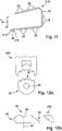
  • 11 eine Ausgestaltung eines Lichtleiters mit mehrfach bogenförmig gekrümmt verlaufender Lichtaustrittsfläche; und
  • 12 Ausgestaltungen der Einkoppeloptik und einer zugehörigen Transport- und Umlenkoptik.
Embodiments of the invention are shown in the drawings and are explained in more detail in the following description. They show, each in schematic form:
  • 1 an embodiment of a lighting device according to the invention in a longitudinal section;
  • 2 an embodiment of a light guide having features of the invention;
  • 3 an embodiment of a coupling module that is implemented as a separate component;
  • 4 an alternative embodiment of a coupling module, which is also implemented as a separate component;
  • 5 an embodiment of a transport and deflection optics, in particular according to a recording for a coupling optics 3 forms;
  • 6 an embodiment of a light guide in a plan view;
  • 7 an assembly of a light guide, light-emitting diodes, a circuit board and a heat sink;
  • 8th an embodiment of an arrangement of a light source and a light guide;
  • 9 an arrangement of a board with one or more LEDs, a coupling optics and a transport and deflection optics;
  • 10 an embodiment of a light guide, the coupling optics of which have a first light coupling surface and a second light coupling surface;
  • 11 an embodiment of a light guide with a light exit surface that is curved multiple times in an arc; and
  • 12 Configurations of the coupling optics and an associated transport and deflection optics.

Gleiche Bezugszeichen in verschiedenen Figuren bezeichnen dabei jeweils gleiche oder zumindest ihrer Funktion nach vergleichbare Elemente.The same reference symbols in different figures denote the same elements or elements that are at least comparable in terms of their function.

Die 1 zeigt ein Ausführungsbeispiel einer erfindungsgemäßen Kraftfahrzeugbeleuchtungseinrichtung 10. Die Beleuchtungseinrichtung 10 besitzt ein Gehäuse 12, dessen Lichtaustrittsöffnung mit einer transparenten Abdeckscheibe 14 abgedeckt ist. In dem Gehäuse 12 sind ein Lichtleiter 16 und eine Lichtquelle 18 angeordnet. Aus Platzgründen ist der Lichtleiter 16 in x-Richtung verkürzt dargestellt. Die x-Richtung entspricht hier einer Hauptabstrahlrichtung. Bei einer bestimmungsgemäßen Verwendung der Beleuchtungseinrichtung in einem Straßenkraftfahrzeug ist dies zum Beispiel die Vorwärtsfahrtrichtung oder die Rückwärtsfahrtrichtung. Die y-Richtung ist parallel zu einer Querachse und die z-Richtung ist parallel zu einer Hochachse des Fahrzeugs. Die Lichtquelle 38 ist auf einem zur elektrischen Kontaktierung dienenden Trägerelement 46 angeordnet, das hier auch einen Kühlkörper mit umfasst.The 1 shows an exemplary embodiment of a motor vehicle lighting device 10 according to the invention. The lighting device 10 has a housing 12 whose light exit opening is covered with a transparent cover plate 14 . A light guide 16 and a light source 18 are arranged in the housing 12 . For reasons of space, the light guide 16 is shown shortened in the x-direction. The x-direction here corresponds to a main emission direction. If the lighting device is used as intended in a road motor vehicle, this is, for example, the forward direction or the reverse direction. The y-direction is parallel to a lateral axis and the z-direction is parallel to a vertical axis of the vehicle. The light source 38 is arranged on a carrier element 46 which is used for electrical contacting and which here also includes a heat sink.

Die Lichtquelle 38 ist bevorzugt eine Halbleiterlichtquelle in Form einer Licht emittierenden Diode (LED). Die LED besitzt eine ebene Lichtaustrittsfläche. Solche Halbleiterlichtquellen können näherungsweise als Lambert-Strahler betrachtet werden, die ihr Licht über einen Winkelbereich von 90 Grad zu einer Normalen der LED-Lichtaustrittsfläche in einen Halbraum mit Raumwinkel 2Π emittieren. Eine Hauptabstrahlrichtung der Lichtquelle 38 weist in der 2 nach oben und fällt mit einer weiter unten näher erläuterten Rotationsachse 28 zusammen.The light source 38 is preferably a semiconductor light source in the form of a light emitting diode (LED). The LED has a flat light exit surface. Such semiconductor light sources can be viewed approximately as Lambert emitters, which emit their light over an angular range of 90 degrees to a normal of the LED light exit surface in a half-space with a solid angle of 2Π. A main emission direction of the light source 38 has in the 2 upwards and coincides with an axis of rotation 28 explained in more detail below.

Der Lichtleiter weist eine erste Seite 20, eine der ersten Seite 20 gegenüberliegende zweite Seite 22 und eine zwischen einem Rand der ersten Seite 20 und einem Rand der zweiten Seite 22 liegende und die erste Seite mit der zweiten Seite verbindende Schmalseite auf. Die erste Seite 20 und die zweite Seite 22 liegen hier zur x-y-Ebene des angegebenen Koordinatensystems parallel. Es ist aber für die Erfindung nicht zwingend erforderlich, dass die erste Seite parallel zur zweiten Seite ist. Die Abmessungen der ersten Seite 12 und der zweiten Seite 14 sind groß im Verhältnis zur Breite der Schmalseite, die dem Abstand der ersten Seite zu der zweiten Seite entspricht. Dieses große Verhältnis prägt das Erscheinungsbild des Lichtleiters 10 als plattenförmiges Teil. Das Verhältnis ist bevorzugt größer als fünf.The light guide has a first side 20, a second side 22 opposite the first side 20 and a narrow side lying between an edge of the first side 20 and an edge of the second side 22 and connecting the first side to the second side. The first side 20 and the second side 22 are here parallel to the x-y plane of the given coordinate system. However, it is not absolutely necessary for the invention that the first side is parallel to the second side. The dimensions of the first side 12 and the second side 14 are large in relation to the width of the narrow side, which corresponds to the distance from the first side to the second side. This large ratio characterizes the appearance of the light guide 10 as a plate-shaped part. The ratio is preferably greater than five.

Ein hier mit einer Normalen in x-Achsenrichtung liegender Bereich der Schmalseite 20 ist als Lichtaustrittsfläche 24 ausgebildet. Die Ausdehnung der Lichtaustrittsfläche 24 in y-Achsenrichtung ist um ein Vielfaches größer als ihre Ausdehnung in Richtung der z-Achse, wodurch sich eine streifenförmige Gestalt der Lichtaustrittsfläche 24 in der y-z-Ebene ergibt.A region of the narrow side 20 lying here with a normal in the direction of the x-axis is designed as a light exit surface 24 . The extent of the light exit surface 24 in the direction of the y-axis is many times greater than its extent in the direction of the z-axis, resulting in a strip-like shape of the light exit surface 24 in the y-z plane.

Der Lichtleiter 16 weist eine Einkoppeloptik 26 auf. Die Einkoppeloptik 26 weist eine um die Rotationsachse 28 rotationssymmetrische Lichteinkoppelfläche 30 auf, die in Ebenen, in denen die Rotationsachse 28 und eine von der Rotationsachse 28 rechtwinklig-radial ausgehende Radialrichtung 32 liegt, eine von außerhalb der Einkoppeloptik 26 konvex erscheinende Krümmung besitzt. Solche Ebenen stellen zweite Ebenen im Sinne dieser Anmeldung dar und können wegen ihrer radialen Ausrichtung als Radialebenen bezeichnet werden. Die Zeichnungsebene der 1 entspricht einer solchen Radialebene. Die Einkoppelfläche 30 ist hier eine Grenzfläche einer Vertiefung 34 in einem aus der zweiten Seite 22 herausragenden Vorsprung 36. Der Vorsprung 36 hat außen die Form eines Kegelstumpfes, der sich in Richtung zur zweiten Seite hin verbreitert.The light guide 16 has a coupling optics 26 . The coupling optics 26 has a light coupling surface 30 that is rotationally symmetrical about the axis of rotation 28 and has a curvature that appears convex from outside the coupling optics 26 in planes in which the axis of rotation 28 and a radial direction 32 extending perpendicularly and radially from the axis of rotation 28 are located. Such planes represent second planes within the meaning of this application and can be referred to as radial planes because of their radial alignment. The drawing level of 1 corresponds to such a radial plane. The coupling surface 30 is here a boundary surface of a depression 34 in a projection 36 protruding from the second side 22. The projection 36 has the shape of a truncated cone on the outside, which widens towards the second side.

Die Einkoppeloptik 26 weist ferner einen rotationssymmetrisch zu der Rotationsachse 28 angeordneten ersten Reflektor 38 auf. Der erste Reflektor 38 ist die Grenzfläche einer Vertiefung 40 in der ersten Seite 20 des Lichtleiters. Die Vertiefung hat die Form eines Kegelstumpfes, der sich in Richtung zur zweiten Seite 22 des Lichtleiters hin verjüngt. Die Grenzfläche der Vertiefung ist darüber hinaus bevorzugt so geformt, dass das von einer auf der Rotationsachse liegenden Lichtquelle her auf sie einfallende Licht dort eine interne Totalreflexion erfährt.The coupling optics 26 also have a first reflector 38 arranged rotationally symmetrically to the axis of rotation 28 . The first reflector 38 is the interface of a recess 40 in the first side 20 of the light guide. The recess has the shape of a truncated cone that tapers towards the second side 22 of the light guide. The boundary surface of the depression is also preferably shaped in such a way that the light incident on it from a light source lying on the axis of rotation experiences total internal reflection there.

Alternativ oder ergänzend ist die reflektierende Fläche des ersten Reflektors 32 verspiegelt, beispielsweise durch eine darauf aufgebrachte Metallschicht. Dies gilt analog für alle in dieser Anmeldung genannten reflektierenden Flächen. Es ist jedoch bevorzugt, diese Flächen, soweit es die Winkelverhältnisse jeweils erlauben, als intern totalreflektierende Grenzflächen auszugestalten, weil bei internen Totalreflexionen weniger Verluste auftreten als an verspiegelten Grenzflächen, was für das angestrebte Ziel einer hohen Effizienz hilfreich ist. Bevorzugt sind Ausgestaltungen ohne aufzubringende spiegelnde Schichten auch deshalb, weil Beschichtungsvorgänge aufwändig und teuer sind.Alternatively or additionally, the reflecting surface of the first reflector 32 is mirrored, for example by a metal layer applied thereto. This applies analogously to all reflecting surfaces mentioned in this application. However, it is preferred to design these surfaces as internally totally reflecting boundary surfaces, as far as the angular relationships allow, because fewer losses occur with internal total reflections than on mirrored boundary surfaces, which is helpful for the desired goal of high efficiency. Configurations without reflective layers to be applied are also preferred because coating processes are complex and expensive.

Die Lichtquelle 18 ist auf der Rotationsachse 28 so angeordnet, dass ihre Hauptabstrahlrichtung auf der Rotationsachse 28 liegt und zur Einkoppeloptik 26 weist. Die in den Radialebenen liegende konvexe Krümmung der Lichteintrittsfläche 30 der Einkoppeloptik 26 ist achsensymmetrisch zu einer gedachten Gerade 42, welche die Radialrichtung 32 schneidet und welche die Rotationsachse 28 am Ort der Lichtquelle 18, insbesondere in der Lichtaustrittsfläche der Lichtquelle schneidet. Eine solche Gerade 42 liegt in jeder Radialebene, so dass alle derartigen Radialebenen auf dem Mantel eines gedachten Kegels liegen, dessen Spitze in der Lichtaustrittsfläche der Lichtquelle 18 liegt. Der Öffnungswinkel des von der Lichtquelle ausgehenden Lichtbündels wird durch die Brechung an dieser Lichteintrittsfläche 30 in den zweiten Ebenen verringert. Der Krümmungsgrad der konvexen Krümmung, die Brechzahl des transparenten Materials der Einkoppeloptik 26 und die Anordnung der Lichtquelle 18 sind so aufeinander abgestimmt, dass über die konvex gekrümmte Lichteintrittsfläche eingekoppelte Lichtstrahlen innerhalb einer jeden zweiten Ebene parallel zu der Geraden 42 verlaufen.The light source 18 is arranged on the axis of rotation 28 in such a way that its main emission direction lies on the axis of rotation 28 and points towards the coupling optics 26 . The convex curvature of the light entry surface 30 of the coupling optics 26 lying in the radial planes is axisymmetric to an imaginary straight line 42 which intersects the radial direction 32 and which intersects the axis of rotation 28 at the location of the light source 18, in particular in the light exit surface of the light source. Such a straight line 42 lies in each radial plane, so that all such radial planes lie on the surface of an imaginary cone, the apex of which lies in the light exit surface of the light source 18 . The aperture angle of the light bundle emitted by the light source is reduced in the second planes by the refraction at this light entry surface 30 . The degree of curvature of the convex curvature, the refractive index of the transparent material of the in-coupling optics 26 and the arrangement of the light source 18 are matched to one another such that light beams coupled in via the convexly curved light entry surface run parallel to the straight line 42 within every second plane.

Von der Lichtquelle 18 geht Licht in einen Raumwinkel aus, in dessen Zentrum die Achse 28 liegt. Dieses Licht fällt zumindest teilweise auf den ersten Reflektor 38 und wird von dort so reflektiert, dass die reflektierten Lichtstrahlen in erste Ebenen, die in der 1 parallel zu der x-y-Ebene liegen, umgelenkt werden. Radial zur Achse 28 liegende Richtungskomponenten der Lichtstrahlen bleiben wegen der Rotationssymmetrie des ersten Reflektors 38 zur Achse 28 zunächst erhalten.Light emanates from the light source 18 in a solid angle at the center of which the axis 28 lies. This light is at least partially incident on the first reflector 38 and is reflected from there in such a way that the reflected light beams enter the first planes in the 1 lie parallel to the xy plane, are deflected. Directional components of the light beams that are radial to the axis 28 are initially retained because of the rotational symmetry of the first reflector 38 with respect to the axis 28 .

Die Lichtquelle 18 strahlt somit von unten gegen die den ersten Reflektor 38 darstellende Vertiefung 40. Die Vertiefung 40 durchdringt den Lichtleiter 10 nicht vollständig. Ihre Tiefe und damit der Abstand ihrer tiefsten Stellen 44 von der ersten Seite 20 ist etwa gleich der Hälfte der Plattenbreite, wobei die Plattenbreite dem außerhalb der Vertiefung 40 und außerhalb des Vorsprungs 36 gemessenen Abstand der ersten Seite 20 von zweiten Seite 22 entspricht.The light source 18 thus radiates from below against the depression 40 representing the first reflector 38. The depression 40 does not penetrate the light guide 10 completely. Their depth and thus the distance between their deepest points 44 and the first side 20 is approximately equal to half the width of the plate, the width of the plate corresponding to the distance between the first side 20 and the second side 22 measured outside of the depression 40 and outside of the projection 36 .

Die Achse 28 teilt den Lichtleiter 16 in x-Richtung in einen vorderen Bereich, welcher der Lichtaustrittsfläche 24 zugewandt ist und der zwischen der Achse 28 und dieser Lichtaustrittsfläche 24 liegt, und einen hinteren Bereich, der hier durch einen zweiten Reflektor 46 begrenzt ist und der somit zwischen dem zweiten Reflektor 46 und der Achse 28 liegt.The axis 28 divides the light guide 16 in the x-direction into a front area, which faces the light exit surface 24 and which lies between the axis 28 and this light exit surface 24, and a rear area, which is delimited here by a second reflector 46 and the thus between the second reflector 46 and the axis 28 is located.

Der zweite Reflektor 47 ist hier als Umkehrreflektor ausgeführt. Der Umkehrreflektor weist eine erste Reflektorfläche 48 und eine zweite Reflektorfläche 50 auf, die so gegeneinander geneigt sind, dass ein auf eine der beiden Reflektorflächen auftreffender Lichtstrahl zunächst zu der anderen Reflektorfläche reflektiert wird. An dieser anderen Reflektorfläche wird der Lichtstrahl bei der Reflexion nochmals umgelenkt, so dass seine Richtung entgegengesetzt zu der Richtung ist, aus der der Lichtstrahl zuerst auf eine der beiden Reflektorflächen eingefallen ist.The second reflector 47 is designed here as a reverse reflector. The reversible reflector has a first reflector surface 48 and a second reflector surface 50 which are inclined relative to one another in such a way that a light beam impinging on one of the two reflector surfaces is initially reflected to the other reflector surface. On this other reflector surface, the light beam is deflected again during reflection, so that its direction is opposite to the direction from which the light beam first struck one of the two reflector surfaces.

Aufgrund der beiden dachartig gegeneinander geneigten Reflektorflächen 48 und 50 wird der zweite Reflektor 46 auch als Dachkantenreflektor bezeichnet. In ersten Ebenen, also beispielsweise in einer zur Zeichnungsebene der 2 senkrechten Ebene, in der die Radialrichtung 32 liegt, weist der zweite Reflektor 46 eine halbkreisförmige Gestalt auf, die über den Halbkreis betrachtet konzentrisch zur kreisförmigen Grundfläche des ersten Reflektors 38 und damit koaxial zur Achse 28 ist.Because of the two reflector surfaces 48 and 50 inclined towards one another like a roof, the second reflector 46 is also referred to as a roof edge reflector. In the first levels, for example in one of the drawing level 2 vertical In the plane in which the radial direction 32 lies, the second reflector 46 has a semicircular shape which, viewed over the semicircle, is concentric with the circular base area of the first reflector 38 and thus coaxial with the axis 28 .

Licht 52, das auf eine im vorderen Bereich liegende Fläche des ersten Reflektors 38 trifft, wird an dieser so reflektiert, dass es im vorderen Bereich weiter propagiert. Licht 54, das auf eine im hinteren Bereich liegende Fläche des ersten Reflektors 38 trifft, wird an dieser zunächst zum zweiten Reflektor 46 gelenkt.Light 52 that strikes a surface of the first reflector 38 that is in the front area is reflected on it in such a way that it propagates further in the front area. Light 54 which strikes a surface of the first reflector 38 located in the rear region is first directed to the second reflector 46 on this surface.

Die Konturen des ersten Reflektors 38 verlaufen in jeder Radialebene geradlinig. Daher werden in einer solchen Radialebene parallel zueinander einfallende Lichtstrahlen durch die Reflexionen in parallel zueinander ausgehende Strahlen überführt.The contours of the first reflector 38 run in a straight line in each radial plane. Therefore, in such a radial plane, light beams incident parallel to one another are converted by the reflections into beams exiting parallel to one another.

Neben der in der Zeichnungsebene liegenden zweiten Ebene existiert noch eine Vielzahl anderer zweiter Ebenen. Allen zweiten Ebenen gemeinsam ist, dass sie durch die Achse 28 und einen Lichtstrahl 52 oder 54 nach dessen Reflexion am ersten Reflektor aufgespannt werden. Die reflektierten Lichtstrahlen 52 und 54 weisen radial von der Achse 28 der Einkoppeloptik 26 weg oder weisen zumindest eine Radialkomponente auf.In addition to the second level lying in the drawing level, there are also a large number of other second levels. What all second planes have in common is that they are spanned by the axis 28 and a light beam 52 or 54 after it has been reflected at the first reflector. The reflected light beams 52 and 54 point radially away from the axis 28 of the coupling optics 26 or have at least one radial component.

Die reflektierten Lichtstrahlen 52 oder 54 definieren eine Schnittlinie, die die zweite Ebene mit der ersten Ebene gemeinsam hat. Die erste Ebene steht dabei senkrecht zu der zweiten Ebene. Im Prinzip lässt sich zu jedem von dem ersten Reflektor 38 reflektierten Lichtstrahl 52 und 54 ein solches Paar, bestehend aus erster Ebene und dazu senkrecht stehender zweiter Ebene, finden.The reflected light rays 52 or 54 define a line of intersection which the second plane shares with the first plane. The first level is perpendicular to the second level. In principle, such a pair consisting of a first plane and a second plane perpendicular thereto can be found for each light beam 52 and 54 reflected by the first reflector 38 .

Eine Mittelebene, die die Radialrichtungen 32 enthält und senkrecht zur Rotationsachse 28 liegt, teilt den Lichtleiter 10 in eine obere Hälfte 56, in der die Vertiefung 40 oder zumindest der größere Teil der Vertiefung 40 liegt, und eine untere Hälfte 58, in die allenfalls höchstens nur noch die tiefsten Stellen der Vertiefung 40 hineinragen. Die untere Hälfte 58 ist der Lichtquelle 18 zugewandt. Sie liegt also zwischen der Lichtquelle 18 und der ersten Hälfte 56 und damit zwischen der Lichtquelle 18 und der Vertiefung 40. Die an der im hinteren Bereich liegenden Fläche des ersten Reflektors reflektierten Lichtstrahlen 54 treffen auf die erste Reflektorfläche 48 des zweiten Reflektors 46. Die erste Reflektorfläche 48 ist so gegen die Mittelebene des Lichtleiters 10 geneigt, dass dort auftreffende Lichtstrahlen in Richtung der zweiten Reflektorfläche 50 gelenkt werden.A central plane, which contains the radial directions 32 and is perpendicular to the axis of rotation 28, divides the light guide 10 into an upper half 56, in which the depression 40 or at least the larger part of the depression 40 lies, and a lower half 58, in which at most only the deepest parts of the depression 40 protrude. The lower half 58 faces the light source 18 . It is therefore located between the light source 18 and the first half 56 and thus between the light source 18 and the depression 40. The light beams 54 reflected on the surface of the first reflector located in the rear region impinge on the first reflector surface 48 of the second reflector 46. The first Reflector surface 48 is inclined relative to the center plane of light guide 10 in such a way that light rays impinging there are directed in the direction of second reflector surface 50 .

An der zweiten Reflektorfläche 50 werden die an der ersten Reflektorfläche 48 umgelenkten Lichtstrahlen 54 in Richtung der Rotationsachse 28 und damit in Richtung zu dem vorderen Bereich des Lichtleiters 16 reflektiert. Aufgrund der in den ersten Ebenen halbkreisförmigen Geometrie des zweiten Reflektors 46 reflektiert der zweite Reflektor 46 das vom ersten Reflektor 38 her radial einfallende Licht in der zur Einfallsrichtung entgegengesetzten Radialrichtung zurück. Dabei wird das reflektierte Licht in der zweiten Ebene zweimal hintereinander rechtwinklig zu seiner jeweiligen Einfallsrichtung umgelenkt. Dabei wird zunächst in der oberen Hälfte 56 propagierendes Licht in die untere Hälfte 58 umgelenkt.The light beams 54 deflected on the first reflector surface 48 are reflected on the second reflector surface 50 in the direction of the axis of rotation 28 and thus in the direction of the front region of the light guide 16 . Due to the semicircular geometry of the second reflector 46 in the first planes, the second reflector 46 reflects the light radially incident from the first reflector 38 back in the radial direction opposite to the direction of incidence. The reflected light in the second plane is deflected twice in a row at right angles to its respective direction of incidence. In this case, light propagating in the upper half 56 is first deflected into the lower half 58 .

Da der erste Reflektor 38 die untere Hälfte 58 nicht vollständig durchdringt, propagiert das Licht unterhalb des ersten Reflektors 38 durch die untere Hälfte 58 des Lichtleiters 16 in den vorderen Bereich des Lichtleiters 16 und wird dabei nicht durch den ersten Reflektor gestört. Since the first reflector 38 does not completely penetrate the lower half 58, the light below the first reflector 38 propagates through the lower half 58 of the light guide 16 into the front area of the light guide 16 and is not disturbed by the first reflector.

Die Kegelstumpf-förmige Form des ersten Reflektors 38 und der als Umkehrreflektor ausgestaltete zweite Reflektor 46 bewirken, dass die Lichtstrahlen 52, die vom ersten Reflektor 38 aus in den vom zweiten Reflektor 46 abgewandten vorderen Bereich des Lichtleiters ausgehen, in der 1 oberhalb der Mittelebene des Lichtleiters propagieren. Die Lichtstrahlen 54, die vom ersten Reflektor 38 in einen dem zweiten Reflektor 46 zugewandten hinteren Bereich des Lichtleiters ausgehen, erfahren eine zweifache Reflexion an dem Umkehrreflektor 46, die eine Richtungsumkehr und eine Höhenverschiebung der Lichtstrahlen 54 bewirkt. Somit propagieren die Lichtstrahlen 54 in der 1 unterhalb der Mittelebene. In Verbindung mit einer innerhalb der zweiten Ebenen parallelen Ausrichtung der Lichtstrahlen ergibt sich dann der Vorteil einer über ihre Ausdehnung längs der z-Achse gleichmäßigen Beleuchtung der Lichtaustrittsfläche 24.The truncated cone shape of the first reflector 38 and the second reflector 46 designed as a reverse reflector cause the light beams 52, which emanate from the first reflector 38 into the front region of the light guide facing away from the second reflector 46, in the 1 propagate above the center plane of the light guide. The light beams 54, which emanate from the first reflector 38 in a rear region of the light guide facing the second reflector 46, undergo a double reflection at the reversing reflector 46, which causes the light beams 54 to change direction and shift in height. Thus, the light rays 54 propagate in the 1 below the midplane. In connection with a parallel alignment of the light beams within the second planes, the advantage then results that the light exit surface 24 is illuminated uniformly over their extent along the z-axis.

Eine Dicke des Lichtleiters ist hier außerhalb des Vorsprungs 36 und der Vertiefung 40 nicht kleiner als die doppelte Tiefe des Umlenkreflektors. Die Einkoppeloptik weist einen Dachkantenreflektor auf.A thickness of the light guide outside of the projection 36 and the recess 40 is not less than twice the depth of the deflection reflector. The coupling optics have a roof edge reflector.

Der erste Reflektor 38 ist rotationssymmetrisch. Das hat zur Folge, dass in Bezug auf die Achse 28 radiale Richtungskomponenten des Lichtes der Lichtquelle 18 bei der Reflexion am ersten Reflektor nicht verändert werden und damit erhalten bleiben. Das Licht ist daher in den ersten Ebenen nicht parallel, sondern radial ausgerichtet. Der Lichtleiter 16 weist zusätzlich Strukturen 60 auf, die dazu eingerichtet sind, im Lichtleiter 16 in den ersten Ebenen propagierendes Licht so umzulenken, dass die Lichtaustrittsfläche 24 des Lichtleiters 16 aus dessen Innerem auch längs der ersten Ebenen gleichmäßig hell mit weitgehend parallel ausgerichtetem Licht beleuchtet wird. The first reflector 38 is rotationally symmetrical. The consequence of this is that with respect to the axis 28, radial directional components of the light from the light source 18 are not changed during reflection at the first reflector and are therefore retained. The light is therefore not parallel in the first planes, but is aligned radially. The light guide 16 also has structures 60 which are set up to deflect light propagating in the first planes in the light guide 16 in such a way that the light exit surface 24 of the light guide 16 from its interior is also uniformly brightly illuminated along the first planes with light that is aligned largely in parallel .

In der 1 ist dies insbesondere dann der Fall, wenn das Licht in zur x-y-Ebene parallelen Ebenen parallel ausgerichtet ist und dabei längs der y-Richtung gleichmäßig verteilt ist. Mit solchem Licht kann leicht eine regelkonforme Lichtverteilung erzeugt werden, die sich zum Beispiel über eine horizontale Winkelbreite von +/- 20° und eine vertikale Winkelbreite von +/- 10° erstreckt. Beim Gegenstand der 1 weisen diese Strukturen 60 eine Luftlinse 62 auf, die das in den ersten Ebenen zunächst radial zur Achse 28 propagierende Licht bündelt und dabei insbesondere parallel ausrichtet.In the 1 this is the case in particular when the light is aligned in parallel in planes parallel to the xy plane and is uniformly distributed along the y direction. With such light, a light distribution that conforms to the rules can easily be generated, which extends, for example, over a horizontal angular width of +/-20° and a vertical angular width of +/-10°. At the subject of 1 For example, these structures 60 have an air lens 62 that bundles the light that first propagates radially to the axis 28 in the first planes and aligns it, in particular, in parallel.

Eine Funktionsweise der Strukturen 60 wird weiter unten anhand weiterer Figuren detailliert beschrieben.A mode of operation of the structures 60 is described in detail below with reference to additional figures.

Die Umformung des parallelen Lichtes in eine regelkonforme Lichtverteilung erfolgt zum Beispiel mit kissenförmigen oder Zylindermantelabschnitts-förmigen Streuoptiken in der Lichtaustrittsfläche des Lichtleiters.The conversion of the parallel light into a light distribution that conforms to the rules is carried out, for example, with scattering optics in the form of cushions or sections of a cylinder jacket in the light exit surface of the light guide.

2 zeigt ein Ausführungsbeispiel eines Merkmale der Erfindung aufweisenden Lichtleiters 116. Der Lichtleiter 116 unterscheidet sich vom Lichtleiter 16 nach der 1 insbesondere dadurch, dass er den als Dachkantenreflektor verwirklichten und als Umkehrreflektor wirkenden zweiten Reflektor 46 nicht aufweist. In Bezug auf seine Abmessungen zeichnet sich der Lichtleiter 116 dadurch aus, dass eine Dicke des Lichtleiters 116 außerhalb des Vorsprungs 36 und außerhalb der Vertiefung 40 nicht kleiner als die Tiefe des ersten Reflektors 38 und damit nicht kleiner als die Tiefe der Vertiefung 40 ist. 2 12 shows an exemplary embodiment of a light guide 116 having features of the invention. The light guide 116 differs from the light guide 16 according to FIG 1 in particular in that it does not have the second reflector 46, which is implemented as a roof edge reflector and acts as a reversing reflector. With regard to its dimensions, the light guide 116 is characterized in that a thickness of the light guide 116 outside of the projection 36 and outside of the recess 40 is not smaller than the depth of the first reflector 38 and thus not smaller than the depth of the recess 40 .

Bei dieser Ausgestaltung erfolgt die Umlenkung des Lichtes, das von dem ersten Reflektor in den von der Lichtaustrittsfläche 24 abgewandten Halbraum ausgeht, in den der Lichtaustrittsfläche 24 zugewandten Halbraum nicht durch einen Dachkantenreflektor, sondern durch Umlenkstrukturen, wie sie weiter unten unter Bezug auf die 6 erläutert werden. Auch hier gilt, dass der Lichtleiter 116 Strukturen 60 aufweist, die dazu eingerichtet sind, in dem Lichtleiter 116 propagierendes Licht, dass sich in Bezug auf die Achse 28 nach der Reflexion am ersten Reflektor 38 zunächst radial ausbreitet, so umzulenken, dass die Lichtaustrittsfläche 24 des Lichtleiters 116 aus dessen Innerem gleichmäßig hell mit weitgehend parallel ausgerichtetem Licht beleuchtet wird.In this configuration, the deflection of the light that emanates from the first reflector into the half-space facing away from light exit surface 24 into the half-space facing light exit surface 24 is not effected by a roof edge reflector, but rather by deflection structures, as described below with reference to 6 be explained. It also applies here that the light guide 116 has structures 60 that are set up to deflect light propagating in the light guide 116, which initially propagates radially with respect to the axis 28 after being reflected at the first reflector 38, in such a way that the light exit surface 24 of the light guide 116 from the interior of which is uniformly brightly illuminated with largely parallel light.

3 zeigt eine Ausgestaltung eines Einkoppelmoduls 26, das hier als separates Bauteil verwirklicht ist. Bei dieser Realisierung weist der Lichtleiter, sei es der Lichtleiter 16 oder der Lichtleiter 116 oder eine andere Ausgestaltung eines Lichtleiters, der die beschriebenen Eigenschaften besitzt, neben der Einkoppeloptik 26 noch eine zu dieser Einkoppeloptik komplementäre Transport- und Umlenkoptik auf, welche die Einkoppeloptik zu dem beschriebenen Lichtleiter ergänzt. Eine solche Transport- und Umlenkoptik wird weiter unten noch näher erläutert. 3 shows an embodiment of a coupling module 26, which is realized here as a separate component. In this implementation, the light guide, whether it is light guide 16 or light guide 116 or another configuration of a light guide that has the properties described, has transport and deflection optics that are complementary to these coupling optics in addition to the coupling optics 26, which connect the coupling optics to the described light guide added. Such transport and deflection optics are explained in more detail below.

3 a zeigt eine Ansicht der Einkoppeloptik, die sich einem Betrachter bietet, der sich in der 1 auf der x-Achse links befindet und daher frontal auf den Dachkantenreflektor 46 blickt. 3b zeigt eine Seitenansicht des Einkoppelmoduls mit einer Lichtaustrittsfläche 80, über die Licht aus dem Einkoppelmodul in den Rest des Lichtleiters übertritt. 3 c zeigt einen Schnitt längs der Linie 3c-3c in 3 d, die eine Draufsicht zeigt. Die Ebene der Draufsicht ist bevorzugt parallel zu den oben genannten ersten Ebenen. 3 e zeigt eine perspektivische Ansicht der Einkoppeloptik 26. 3 a shows a view of the coupling optics, which offers a viewer who is in the 1 is located on the left on the x-axis and therefore faces the roof edge reflector 46 . 3b shows a side view of the coupling module with a light exit surface 80, via which light passes from the coupling module into the rest of the light guide. 3 c shows a section along line 3c-3c in 3d , showing a top view. The plan view plane is preferably parallel to the first planes mentioned above. 3 e shows a perspective view of the coupling optics 26.

Die Einkoppeloptik 26 ist hier abschnittsweise kreisförmig berandet. Der Dachkantenreflektor 46 erstreckt sich über einen Halbkreis. Der dazu komplementäre Halbkreis 82 wird durch eine Halbzylindermantelförmige Lichtaustrittsfläche 80 der Einkoppeloptik begrenzt. Der Mittelpunkt beider Halbkreise liegt auf der Achse 28. Der Radius des äußeren Randes der Dachkante ist bevorzugt größer als der Radius des Halbzylindermantels 82. Dadurch kann der über den Halbzylindermantel hinausstehende Teil der Dachkante als Anschlagfläche verwendet werden, was die Positionierungsgenauigkeit beim Zusammenfügen der Bauteil verbessert.The in-coupling optics 26 have circular borders here in sections. The roof edge reflector 46 extends over a semicircle. The semicircle 82 complementary thereto is delimited by a light exit surface 80 of the coupling optics in the shape of a semicylindrical jacket. The center of both semicircles lies on the axis 28. The radius of the outer edge of the roof edge is preferably larger than the radius of the semi-cylindrical shell 82. This allows the part of the roof edge protruding beyond the semi-cylindrical shell to be used as a stop surface, which improves the positioning accuracy when assembling the component .

Der Gegenstand der 3 ist insbesondere zu dem Gegenstand der 1 kompatibel und kann sowohl als separater Bestandteil des Lichtleiters 16 als auch als einstückig stoffschlüssig mit dem Rest des Lichtleiters 16 zusammenhängender Bestandteil des Lichtleiters 16 verwirklicht sein.The subject of 3 is particularly to the subject of 1 compatible and can be implemented both as a separate component of the light guide 16 and as a one-piece cohesive component of the light guide 16 with the rest of the light guide 16 .

4 zeigt eine alternative Ausgestaltung eines Einkoppelmoduls 26, das hier ebenfalls als separates Bauteil verwirklicht ist. 4 a zeigt eine Seitenansicht des hier um die Achse 28 rotationssymmetrischen Einkoppelmoduls 26 mit einer Lichtaustrittsfläche 80, über die Licht aus dem Einkoppelmodul in den Rest des Lichtleiters übertritt. 4 b zeigt einen Schnitt längs der Linie 3b-3b in 3 c, die eine Draufsicht zeigt. Die Ebene der Draufsicht ist bevorzugt parallel zu den oben genannten ersten Ebenen. 4 d zeigt eine perspektivische Ansicht der Einkoppeloptik 26. Die Einkoppeloptik 26 ist hier rotationssymmetrisch kreisförmig berandet. Die Lichtaustrittsfläche 80 hat die Form eines Zylindermantels. Der Mittelpunkt der Kreisform liegt auf der Achse 28. 4 shows an alternative embodiment of a coupling module 26, which is also realized here as a separate component. 4 a shows a side view of the coupling module 26, which is rotationally symmetrical here about the axis 28, with a light exit surface 80, via which the light passes from the coupling module into the rest of the light guide. 4 b shows a section along line 3b-3b in 3 c , showing a top view. The plan view plane is preferably parallel to the first planes mentioned above. 4d shows a perspective view of the in-coupling optics 26. The in-coupling optics 26 here has rotationally symmetrical circular borders. The light exit surface 80 has the shape of a cylinder jacket. The center of the circular shape is on the 28 axis.

Der Gegenstand der 3 ist insbesondere zu dem Gegenstand der 2 kompatibel und kann sowohl als separater Bestandteil des Lichtleiters 116 als auch als einstückig stoffschlüssig mit dem Rest des Lichtleiters 116 zusammenhängender Bestandteil des Lichtleiters 116 verwirklicht sein.The subject of 3 is particularly to the subject of 2 compatible and can be used both as a separate component of the light guide 116 and as a one-piece material connection with the rest of the light guide 116 can be implemented as a coherent part of the light guide 116 .

5 zeigt eine Ausgestaltung einer Transport- und Umlenkoptik 84, die insbesondere mit der Einkoppeloptik 26 nach 3 kompatibel ist und zusammen mit dieser einen Lichtleiter 16 wie in 1 bildet. Die Transport- und Umlenkoptik 84 weist eine Aufnahme 86 auf, die zur Aufnahme einer Einkoppeloptik 26 eingerichtet ist. Über die Lichtaustrittsfläche 80 der Einkoppeloptik 26 austretendes Licht tritt über die hier halbzylinderförmige Lichteintrittsfläche 88 in die Transport- und Umlenkoptik 84 ein. Die Flächen 80 und 88 grenzen dabei bevorzugt unmittelbar aneinander an, so dass die Aufnahme 86 auch zur Halterung und Festlegung der Position der Einkoppeloptik dient. 5 shows an embodiment of a transport and deflection optics 84, in particular with the in-coupling optics 26 3 is compatible and together with this a light guide 16 as in 1 forms. The transport and deflection optics 84 have a receptacle 86 which is set up to accommodate a coupling optics 26 . Light emerging via the light exit surface 80 of the coupling optics 26 enters the transport and deflection optics 84 via the light entry surface 88, which is semicylindrical in this case. In this case, the surfaces 80 and 88 preferably directly adjoin one another, so that the receptacle 86 is also used to hold and fix the position of the in-coupling optics.

Die Transport- und Umlenkoptik 30 weist Strukturen auf, die dazu eingerichtet sind, in der Transport- und Umlenkoptik 84 propagierendes Licht so umzulenken, dass die Lichtaustrittsfläche 22 des Lichtleiters 10 aus dessen Innerem gleichmäßig hell mit weitgehend parallel ausgerichtetem Licht beleuchtet wird. Mit solchem Licht kann leicht eine regelkonforme Lichtverteilung erzeugt werden, die sich zum Beispiel über eine horizontale Winkelbreite von +/- 20° und eine vertikale Winkelbreite von +/- 10° erstreckt. Diese Strukturen werden beim Gegenstand der 5 durch eine zentrale Luftlinse 62 und eine Außenreflektor gebildet, der parabelförmige Außenseitenabschnitte 86 aufweist. Die zentrale Luftlinse ist bevorzugt so geformt, dass sie das von der Achse 28 radial ausgehende Licht parallel ausrichtet und auf die Lichtaustrittsfläche 24 richtet. Die Luftlinse weist bevorzugt eine aus Sicht des dort einfallenden Lichtes konkav-plane Form auf.The transport and deflection optics 30 have structures that are set up to deflect light propagating in the transport and deflection optics 84 such that the light exit surface 22 of the light guide 10 is uniformly brightly illuminated from the inside with largely parallel light. With such light, a light distribution that conforms to the rules can easily be generated, which extends, for example, over a horizontal angular width of +/-20° and a vertical angular width of +/-10°. These structures are the subject of 5 formed by a central air lens 62 and an outer reflector having parabolic outer side portions 86 . The central air lens is preferably shaped in such a way that it aligns the light emanating radially from the axis 28 in parallel and directs it onto the light exit surface 24 . The air lens preferably has a concave-planar shape from the point of view of the light incident there.

Die Parabelabschnitte 86 sind bevorzugt so geformt, dass ihr Brennpunkt auf der Achse 28 liegt, auf der sich auch die Lichtquelle 18 befindet. Dann richten die Parabelabschnitte 86 das auf sie von der Achse 28 radial ausgehende Licht und auf die Abschnitte 86 einfallendes Licht ebenfalls als Bündel parallelen Lichts auf die Lichtaustrittsfläche 24. Die Umformung des parallelen Lichtes in eine regelkonforme Lichtverteilung erfolgt zum Beispiel mit Streuoptiken 90 in der Lichtaustrittsfläche 24 der Transport- und Umlenkoptik 84, beziehungsweise der Lichtaustrittsfläche des Lichtleiters. Die Transport- und Umlenkoptik 84 der 5 kann mit den Einkoppeloptiken der 3 und 4 verwendet werden. Aufgrund der fehlenden Umlenkung, die bei der Einkoppeloptik nach 3 durch die Dachkante erfolgt, ergibt sich bei einer Kombination der Gegenstände der 4 und 5 aber nur die halbe Effizienz.The parabola sections 86 are preferably shaped so that their focus lies on the axis 28 on which the light source 18 is also located. The parabolic sections 86 then direct the light radiating out on them from the axis 28 and the light incident on the sections 86, also as a bundle of parallel light, onto the light exit surface 24. The parallel light is converted into a light distribution that conforms to the rules, for example with diffusing optics 90 in the light exit surface 24 of the transport and deflection optics 84, or the light exit surface of the light guide. The transport and deflection optics 84 of 5 can with the coupling optics of 3 and 4 be used. Due to the lack of deflection, which is required for the in-coupling optics 3 takes place through the roof edge, resulting in a combination of the objects 4 and 5 but only half the efficiency.

6 zeigt eine Ausgestaltung eines Lichtleiters 116, der bei der Verwendung der Einkoppeloptik nach 5 eine gleich hohe Effizienz aufweist wie eine Kombination der Gegenstände der 3 und 5. 6 zeigt insbesondere eine Draufsicht auf einen solchen Lichtleiter. Auch hier gilt, dass die Einkoppeloptik sowohl als separates Bauteil als auch als stoffschlüssiger Bestandteil des Lichtleiters verwirklicht sein kann. 6 shows an embodiment of a light guide 116, the use of the in-coupling optics 5 has the same high efficiency as a combination of the objects of 3 and 5 . 6 shows in particular a plan view of such a light guide. It also applies here that the in-coupling optics can be implemented both as a separate component and as a cohesive part of the light guide.

Der Lichtleiter weist einen vorderen Bereich 92 und einen hinteren Bereich 94 auf. Die Grenze 93 verläuft zwischen dem vorderen Bereich 92 und dem hinteren Bereich 94. Sie verläuft durch die Achse 28. Der vordere Bereich liegt in dem Halbraum, der sich dadurch auszeichnet, dass an dem rotationsymmetrischen ersten Reflektor 38 reflektiertes Licht, das sich in diesem Halbraum ausbreitet, eine zur Lichtaustrittsfläche 24 weisende Richtungskomponente besitzt. Dies ist bei dem hinteren Bereich nicht der Fall. Dort besitzt das sich dort ausbreitende Licht zunächst eine von der Lichtaustrittsfläche weg weisende Richtungskomponente.The light guide has a front area 92 and a rear area 94 . The boundary 93 runs between the front area 92 and the rear area 94. It runs through the axis 28. The front area lies in the half-space, which is characterized in that the rotationally symmetrical first reflector 38 reflected light that is in this half-space propagates, has a directional component pointing to the light exit surface 24 . This is not the case with the rear area. The light propagating there initially has a directional component pointing away from the light exit surface.

Als Strukturen, die dazu eingerichtet sind, in dem Lichtleiter 116, beziehungsweise in dessen als Transport-und Umlenkoptik dienenden Teil propagierendes Licht so umzulenken, dass die Lichtaustrittsfläche 24 des Lichtleiters 116 aus dessen Innerem gleichmäßig hell mit weitgehend parallel ausgerichtetem Licht beleuchtet wird, weist der Gegenstand zwei verschiedene Arten von Ausnehmungen und zwei verschiedene Arten von Außenreflektoren auf.As structures that are set up to deflect light propagating in light guide 116, or in its part that serves as transport and deflection optics, in such a way that light exit surface 24 of light guide 116 is uniformly brightly illuminated from the inside with light that is aligned largely parallel The subject of two different types of recesses and two different types of external reflectors.

Erste Ausnehmungen 62, 100 stellen Luftlinsen dar, die das Licht durch Brechung umlenken. Zweite Ausnehmungen 110, 112 stellen im Inneren des Lichtleiter liegende Reflektoren, insbesondere TIR-Reflektoren dar.First recesses 62, 100 represent air lenses that deflect the light by refraction. Second recesses 110, 112 represent reflectors located inside the light guide, in particular TIR reflectors.

Erste Außenreflektoren 96 zeichnen sich dadurch aus, dass sie einfallendes Licht nur umlenken, ohne die zwischen den einzelnen Strahlen liegenden Winkel zu verändern.First external reflectors 96 are characterized in that they only deflect incident light without changing the angles between the individual beams.

Die ersten Ausnehmungen umfassen eine zentrale Luftlinse 62, die im vorderen Bereich 92 angeordnet ist, und die radial von der Achse 28 aus einfallendes Licht 98 parallel und nach vorn richtet, sowie dezentral angeordnete Luftlinsen 100, die radial von der Achse 28 aus einfallendes Licht 102 parallel und zur Seite auf die ersten Außenreflektoren 96 lenken.The first recesses comprise a central air lens 62, which is arranged in the front region 92 and which directs light 98 which is incident radially from the axis 28 parallel and forwards, and decentrally arranged air lenses 100 which direct the light 102 which is incident radially from the axis 28 steer parallel and to the side onto the first outer reflectors 96.

Die ersten Außenreflektoren 96 sind so angeordnet, dass sie das von den dezentralen Luftlinsen einfallende Licht nach vorn umlenken. Die zweiten Ausnehmungen 110, 112 weisen dem radial von der Achse 28 her einfallenden Licht 104, 106, 108 zugewandte Parabelflächen auf, die das einfallende Licht parallel ausrichten. Im vorderen Bereich liegende zweite Ausnehmungen 110 richten das parallele Licht 104 nach vorn. Im hinteren Bereich liegende zweite Ausnehmungen 112 lenken das parallele Licht 106, 108 zur Seite auf die ersten Außenreflektoren 96, die das Licht nach vorn umlenken. Zweite Außenreflektoren 114 sind parabelförmig und richten das auf sie aus Richtung der Achse 28 radial einfallende Licht parallel aus und zur Seite auf die ersten Außenreflektoren 96, die dieses Licht ebenfalls nach vorn umlenken. Wie man leicht erkennt, könnte man die zweiten Außenreflektoren auch leicht als Innenreflektoren verwirklichen.The first outer reflectors 96 are arranged to redirect the incident light from the decentralized air lenses forward. The second recesses 110, 112 have parabolic surfaces which face the light 104, 106, 108 which is incident radially from the axis 28 and which align the incident light in parallel. Second recesses 110 located in the front area direct the parallel light 104 forward. In the back area Lying second recesses 112 deflect the parallel light 106, 108 to the side onto the first outer reflectors 96, which deflect the light forward. Second outer reflectors 114 are parabolic and direct the light radially incident on them from the direction of axis 28 parallel and to the side onto the first outer reflectors 96, which also deflect this light forward. As can easily be seen, the second external reflectors could also easily be implemented as internal reflectors.

Die Luftlinsen weisen bevorzugt eine aus Sicht des dort einfallenden Lichtes konkav-plane Form auf. Die Parabelabschnitte sind bevorzugt so geformt, dass ihr Brennpunkt auf der Achse 28 liegt, auf der sich auch die Lichtquelle 18 befindet. Auf der Lichtaustrittsfläche 24 sind bevorzugt kissenförmige und oder Zylindermantelabschnitts-förmige Streuoptiken angeordnet, die das parallele Licht in eine regelkonforme Lichtverteilung aufweiten.The air lenses preferably have a concave-planar shape from the point of view of the light incident there. The parabola sections are preferably shaped so that their focus lies on the axis 28 on which the light source 18 is also located. On the light exit surface 24 scattering optics are preferably arranged in the form of cushions and/or sections of a cylinder jacket, which expand the parallel light into a light distribution that conforms to the rules.

7 zeigt eine Baugruppe aus einem Lichtleiter, der aus einer Einkoppeloptik 26 mit Dachkantenreflektor 46, einer Transport- und Umlenkoptik 117 mit Außenreflektor 98, Luftlinse 62 und Innenreflektoren 114 zum Parallelisieren, und einer Lichtquelle mit einer oder mehreren gleichfarbigen oder verschiedenfarbigen Leuchtdioden 118, einer die Leuchtdiode(n) tragenden Platine 120 und einem Kühlkörper 122 besteht. 7 shows an assembly of a light guide consisting of coupling optics 26 with roof edge reflector 46, transport and deflection optics 117 with outer reflector 98, air lens 62 and inner reflectors 114 for parallelization, and a light source with one or more light-emitting diodes 118 of the same color or different colors, one of which is the light-emitting diode (n) supporting circuit board 120 and a heat sink 122 consists.

8 zeigt eine Ausgestaltung einer Anordnung aus einer Lichtquelle 18 und einem Lichtleiter 16, bei der die Parallelisierung in den ersten Ebenen mit Luftlinsen 62 und parabelförmigen Außenreflektoren 98 erfolgt. Die Luftlinsen besitzen hier eine Fresnel-Struktur. Der Brennpunkt der Parabeln liegt auf der Rotationsachse 28 des ersten Reflektors 38. Bei diesem Lichtleiter ist die Einkoppeloptik eine rotationssymmetrische, insbesondere zylinderförmige Einkoppeloptik, wie sie zum Beispiel in der 4 dargestellt ist. Der Lichtleiter weist eine Lichtaustrittsfläche 24 mit eingeformten Streuoptiken auf, die bevorzugt kissenförmig sind oder welche die Form von Teilen von Zylindermänteln haben. Auf der der Lichtaustrittsfläche gegenüberliegenden Seite ist ein gerader Dachkantenreflektor 124 angeordnet. Der Lichtleiter 16 ist ähnlich wie der Lichtleiter 16 aus der 1 in eine obere Hälfte 56 und eine untere Hälfte 58 unterteilt. Die Parallelisierung des Lichtes in den ersten Ebenen erfolgt hier allein in der oberen Hälfte 56. Das in der oberen Hälfte auf den Dachkantenreflektor auftreffende Licht ist in den ersten Ebenen und den zweiten Ebenen parallelisiert und wird durch den Dachkantenreflektor in seiner Richtung umgedreht und so in der Höhe versetzt, dass es in der unteren Hälfte 58 unter dem ersten Reflektor 38 hindurch zur Lichtaustrittsfläche 24 läuft. 8th shows an embodiment of an arrangement made up of a light source 18 and a light guide 16, in which the parallelization in the first planes takes place with air lenses 62 and parabolic external reflectors 98. The air lenses here have a Fresnel structure. The focal point of the parabolas lies on the axis of rotation 28 of the first reflector 38. In this light guide, the coupling optics are rotationally symmetrical, in particular cylindrical coupling optics, as is the case, for example, in FIG 4 is shown. The light guide has a light exit surface 24 with molded scattering optics, which are preferably cushion-shaped or which have the shape of parts of cylinder jackets. A straight roof edge reflector 124 is arranged on the side opposite the light exit surface. The light guide 16 is similar to the light guide 16 from the 1 divided into an upper half 56 and a lower half 58. The parallelization of the light in the first planes takes place here alone in the upper half 56. The light striking the roof edge reflector in the upper half is parallelized in the first planes and the second planes and is reversed in its direction by the roof edge reflector and thus in the Height offset that it runs in the lower half 58 under the first reflector 38 through to the light exit surface 24.

9 zeigt eine Anordnung aus einer Platine 120 mit einer oder mehreren LEDs 118, einer rotationssymmetrischen Einkoppeloptik 26 und einer Transport- und Umlenkoptik, wie sie auch der in 8 dargestellte Lichtleiter 16 aufweist. Wie dort gezeigt, weist die Transport- und Umlenkoptik, die zusammen mit der Einkoppeloptik den Lichtleiter 16 bildet, ergänzende Fresnel-Luftlinsen und Außenreflektoren auf. Das von dem ersten Reflektor 38 in den hinteren Bereich ausgehende Licht 54 wird zunächst über eine Fresnel-Luftlinse in den ersten Ebenen parallelisiert und durch den Dachkantenreflektor 46 nach vorn umgelenkt, wobei es oberhalb des Reflektors 38 am Reflektor 38 vorbei zur Lichtaustrittsfläche 24 gelangt. Das von dem ersten Reflektor 38 in den vorderen Bereich ausgehende Licht 52 wird zunächst über eine Fresnel-Luftlinse 62 in den ersten Ebenen parallelisiert und gelangt anschließend ohne weitere Umlenkung zur Lichtaustrittsfläche 24. 9 shows an arrangement of a circuit board 120 with one or more LEDs 118, a rotationally symmetrical coupling optics 26 and transport and deflection optics, as is also the case in 8th illustrated light guide 16 has. As shown there, the transport and deflection optics, which together with the coupling optics form the light guide 16, have additional Fresnel air lenses and external reflectors. The light 54 emanating from the first reflector 38 in the rear area is initially parallelized in the first planes via a Fresnel air lens and deflected forwards by the roof edge reflector 46, passing the reflector 38 above the reflector 38 to the light exit surface 24. The light 52 emanating from the first reflector 38 in the front area is first parallelized in the first planes via a Fresnel air lens 62 and then reaches the light exit surface 24 without further deflection.

10 zeigt eine Ausgestaltung eines Lichtleiters 16, dessen Einkoppeloptik 26 eine um eine Rotationsachse 28 rotationssymmetrische erste Lichteinkoppelfläche 30 und zweite Lichteinkoppelfläche 31 ufweist. 10 FIG. 1 shows an embodiment of a light guide 16 whose in-coupling optics 26 have a first light in-coupling surface 30 and a second light in-coupling surface 31 that are rotationally symmetrical about an axis of rotation 28 .

Die erste Lichteinkoppelfläche 30 weist in den Radialebenen eine konvexe Krümmung auf. Die in den Radialebenen liegende konvexe Krümmung der ersten Lichteintrittsfläche 30 der Einkoppeloptik 26 ist achsensymmetrisch zu einer gedachten Gerade 42, welche die Radialrichtung 32 schneidet und welche die Rotationsachse 28 am Ort der Lichtquelle 18, insbesondere in der Lichtaustrittsfläche der Lichtquelle schneidet. Insofern unterscheidet sich die Einkoppeloptik der Ausgestaltung gemäß der 10 nicht von den Einkoppeloptiken gemäß den Ausgestaltungen, die unter Bezug auf die 1 bis 4 erläutert worden sind. Unterschiede zu diesen Einkoppeloptiken ergeben sich beim Gegenstand der 10 dadurch, dass dieser Gegenstand die zweite Lichteinkoppelfläche aufweist, die eine Grenzfläche einer zentralen Linse darstellt, die rotationssymmetrisch zu der Achse 28 ist und deren Krümmung achsensymmetrisch zur Achse 28 ist. Bei dieser Ausgestaltung wird daher neben dem rotierten und verkippten Linsenprofil, aus dem die erste Lichteintrittsfläche 30 der Einkoppeloptik besteht, noch eine Zentrallinse verwendet. In jeder Radialebene weist die Kante, über die Licht in die Einkoppeloptik eintritt, dann drei Bereiche auf. Jeder Bereich richtet das über ihn eintretende Licht parallel zu seiner Achsensymmetrieachse aus. Die über die verschiedenen Bereiche eintretenden Bündel sind zueinander nicht parallel. Bei dieser Ausgestaltung besteht der erste Reflektor dann aus zwei Bereichen. Ein erster Bereich 38.1 besitzt die Form eines Mantels eines zur Achse 28 rotationssymmetrischen Kegelstumpfes und ist so angeordnet, dass er das über das Linsenprofil 30 eintretende Licht in erste Ebenen umlenkt.The first light coupling surface 30 has a convex curvature in the radial planes. The convex curvature of the first light entry surface 30 of the coupling optics 26 lying in the radial planes is axisymmetric to an imaginary straight line 42 which intersects the radial direction 32 and which intersects the axis of rotation 28 at the location of the light source 18, in particular in the light exit surface of the light source. In this respect, the coupling optics of the embodiment differs according to FIG 10 not of the Einkupplungsoptiken according to the embodiments, with reference to the 1 until 4 have been explained. Differences to these coupling optics arise in the subject of 10 in that this article has the second light coupling surface which is an interface of a central lens which is rotationally symmetrical about the axis 28 and whose curvature is axisymmetric about the axis 28. In this embodiment, therefore, a central lens is used in addition to the rotated and tilted lens profile of which the first light entry surface 30 of the coupling optics consists. In each radial plane, the edge via which the light enters the in-coupling optics then has three areas. Each region orients the light entering through it parallel to its axisymmetric axis. The beams entering via the different areas are not parallel to each other. In this configuration, the first reflector then consists of two areas. A first region 38.1 has the shape of a shell of a truncated cone which is rotationally symmetrical to the axis 28 and is arranged in such a way that it deflects the light entering via the lens profile 30 into first levels.

Ein zweiter Bereich 38.2 besitzt die Form eines Kegelmantels und ist ebenfalls rotationssymmetrisch zur Achse 28. Auch dieser zweite Bereich 38.2 des ersten Reflektors 38 lenkt das auf ihn von der Lichtquelle her einfallende Licht in die ersten Ebenen um.A second area 38.2 has the shape of a cone shell and is also rotationally symmetrical to the axis 28. This second area 38.2 of the first reflector 38 also deflects the light incident on it from the light source into the first planes.

Aufgrund der unterschiedlichen Winkel zur Achse 28, mit denen sich die von den verschiedenen Bereichen 30, 31 der Lichteintrittsfläche eintretenden Lichtbündel in der Einkoppeloptik 26 ausbreiten, müssen auch die Kegelwinkel (Winkel in der Spitze der Kegel) unterschiedlich sein, um das Licht in untereinander parallele erste Ebenen umzulenken.Due to the different angles to the axis 28, with which the light bundles entering from the different areas 30, 31 of the light entry surface propagate in the in-coupling optics 26, the cone angles (angles at the tips of the cones) must also be different in order to direct the light into parallel redirect first levels.

Der Vorteil dieser Ausgestaltung gegenüber der Ausgestaltung nach den 1 und 2 liegt darin, dass die Einkoppeloptik 26 und damit der Lichtleiter 16 insgesamt flacher sein kann, was Bauraum spart. Die zentrale Linse erfasst nämlich den achsnahen Teil des von der Lichtaustrittsfläche der Lichtquelle ausgehenden Lichtes, der beim Gegenstand der 1 und 2 von den Höhe benötigenden steilen achsnahen Bereichen der Profile 30 erfasst wird. Da die zentrale Linse das Licht nur wenig umlenkt, kann sie sehr flach ausgeführt werden. Beim Gegenstand der 10 konnte daher auf den Vorsprung 36 verzichtet werden.The advantage of this configuration compared to the configuration according to the 1 and 2 is that the coupling optics 26 and thus the light guide 16 can be flatter overall, which saves installation space. The central lens detects namely the near-axis part of the outgoing light from the light exit surface of the light source, the subject of the 1 and 2 is covered by the height-requiring steep areas of the profiles 30 near the axis. Since the central lens deflects the light only slightly, it can be made very flat. At the subject of 10 could therefore be dispensed with the projection 36.

Die 11 zeigt eine Ausgestaltung eines Lichtleiters 216, bei der die Lichtaustrittsfläche 24 u-förmig ausgeführt ist. Die Ansicht bietet sich einem Betrachter, der sich in der Abstrahlrichtung in einiger Entfernung von der Abstrahlrichtung entfernt befindet und auf die Lichtaustrittsfläche blickt. Der Lichtleiter 216 weist mehrere Einkoppeloptiken 26 auf. Man kann sich den Lichtleiter 226 als primär in y-Richtung nebeneinander angeordneter Lichtleiter 16 oder 116 vorstellen, wobei einzelne dieser Lichtleiter um die x-Ache herum gekrümmt sind, um die benötigten Bögen zu erzeugen. Jede der Einkoppeloptiken 26 weist eine ihr zugeordnete Lichtquelle auf. Der Lichtleiter 216 weist Halterungsstrukturen 218 auf, die dazu geeignet und angeordnet sind, den Lichtleiter in dem Gehäuse zu haltern. Die Einkoppeloptiken 26 sind längs der Lichtaustrittsfläche 22 des Lichtleiters verteilt, so dass eine gleichmäßige homogene Beleuchtung der kompliziert geformten bandartigen Lichtaustrittsfläche 22 mit nahezu parallelem Licht gewährleistet ist.The 11 shows an embodiment of a light guide 216, in which the light exit surface 24 is U-shaped. The view is presented to an observer who is some distance away from the emission direction in the emission direction and looks at the light exit surface. The light guide 216 has a plurality of coupling optics 26 . The light guide 226 can be thought of as light guides 16 or 116 arranged side-by-side primarily in the y-direction, with individual ones of these light guides being curved around the x-axis to create the required arcs. Each of the coupling optics 26 has a light source assigned to it. The light guide 216 includes support structures 218 adapted and arranged to support the light guide in the housing. The in-coupling optics 26 are distributed along the light exit surface 22 of the light guide, so that a uniform, homogeneous illumination of the complex-shaped, strip-like light exit surface 22 is ensured with almost parallel light.

Die 12a zeigt eine Ausgestaltung der Einkoppeloptik 26 und einer zugehörigen Transport- und Umlenkoptik 220 in der Draufsicht. Die Lichtaustrittsfläche 80 der Einkoppeloptik 26 ist hier in eine Vielzahl von Einzelflächen unterteilt, die so angeordnet und geformt sind, dass die in den ersten Ebenen liegenden Ausbreitungsrichtungen des Lichts beim Durchtritt durch eine Einzelfläche infolge gezielt verändert werden.The 12a shows an embodiment of the coupling optics 26 and an associated transport and deflection optics 220 in plan view. The light exit surface 80 of the in-coupling optics 26 is divided here into a large number of individual surfaces which are arranged and shaped in such a way that the propagation directions of the light lying in the first planes are selectively changed as a result when passing through an individual surface.

Dadurch ist es möglich, dass ein Öffnungswinkel der in den ersten Ebenen liegenden Ausbreitungsrichtungen des Lichts bereits beim Übergang von der Einkoppeloptik 26 in die Transport- und Umlenkoptik 220 gezielt geändert wird. Die Transport- und Umformoptik 220 ist weniger aufwändig gestaltet, insbesondere können gegebenenfalls die Strukturen 60 zur Parallelisierung in den ersten Ebenen entfallen.This makes it possible for an opening angle of the propagation directions of the light lying in the first planes to be changed in a targeted manner as early as during the transition from the in-coupling optics 26 into the transport and deflection optics 220 . The transport and forming optics 220 are designed to be less complex, in particular the structures 60 for parallelization in the first planes can be omitted if necessary.

In einer weiteren Ausgestaltung, die sich beim Gegenstand der 12a durch eine Kombination mit einer als Negativ der Lichtaustrittsfläche 80 der Einkoppeloptik 26 geformten Lichteintrittsfläche der Transport- und Umlenkoptik 220 ergibt, dienen die resultierenden Verzahnungen als Formschlusselemente zur genauen Positionierung und Halterung der Einkoppeloptik in der Transport-und Umlenkoptik 220.In a further embodiment, which is the subject of 12a through a combination with a light entry surface of the transport and deflection optics 220 shaped as a negative of the light exit surface 80 of the coupling optics 26, the resulting toothings serve as form-fitting elements for the precise positioning and holding of the coupling optics in the transport and deflection optics 220.

12b zeigt eine weitere Ausgestaltung der Einkoppeloptik 26 in einer Schnittdarstellung parallel zu x-z-Ebene. In der dargestellten Ausgestaltung ist die Lichtauskoppelfläche 80 der Einkoppeloptik 26 in eine Vielzahl von Einzelflächen unterteilt. Die Einzelflächen sind dabei stufenartig übereinander angeordnet. Die stufenartige Anordnung der Einzelflächen ermöglicht eine formschlüssige Einpassung der Einkoppeloptik 24 in z-Achsenrichtung in die Transport- und Umlenkoptik 220. 12b shows a further embodiment of the coupling optics 26 in a sectional view parallel to the xz plane. In the embodiment shown, the light coupling-out surface 80 of the coupling-in optics 26 is divided into a large number of individual surfaces. The individual surfaces are arranged in steps one above the other. The stepped arrangement of the individual surfaces enables a form-fitting fit of the coupling optics 24 in the z-axis direction into the transport and deflection optics 220.

Claims (9)

Kraftfahrzeugbeleuchtungseinrichtung mit einer Lichtquelle (18) und mit einem Lichtleiter (16), der eine erste Seite (20), eine der ersten Seite (20) gegenüberliegende zweite Seite (22), und zwischen einem Rand der ersten Seite (20) und einem Rand der zweiten Seite (22) liegende und die erste Seite (20) mit der zweiten Seite (22) verbindende Schmalseiten (24) und eine Licht der Lichtquelle (18) einkoppelnde und umformende Einkoppeloptik (26) aufweist, wobei ein erster Reflektor eine Vertiefung (40) in der ersten Seite (20) des Lichtleiters (16) aufweist und die Form eines Kegelstumpfes besitzt, der sich in Richtung zur zweiten Seite (22) des Lichtleiters (16) hin verjüngt, wobei die Einkoppeloptik (26) mindestens einen Umlenkreflektor (46) aufweist, der einen zweiten Reflektor darstellt und der der von der Lichtquelle (18) in einen Raumwinkel ausgehendes Licht umformt, wobei die Einkoppeloptik (26) eine um eine Rotationsachse (28) rotationssymmetrische Lichteinkoppelfläche (30) aufweist, die in einer bezüglich der Rotationsachse (28) radialen Richtung eine konvexe Krümmung aufweist und die eine Vertiefung (34) in einem aus der zweiten Seite (22) herausragenden Vorsprung (36) ist, wobei der Umlenkreflektor (46) rotationssymmetrisch zu der Rotationsachse (28) ist, und die Lichtquelle (18) auf der Rotationsachse (28) so angeordnet ist, dass ihre Hauptabstrahlrichtung auf der Rotationsachse (28) liegt und zur Einkoppeloptik (26) weist.Motor vehicle lighting device with a light source (18) and with a light guide (16), which has a first side (20), a second side (22) opposite the first side (20), and between an edge of the first side (20) and an edge narrow sides (24) lying on the second side (22) and connecting the first side (20) to the second side (22) and coupling optics (26) coupling and shaping the light of the light source (18), a first reflector having a recess ( 40) in the first side (20) of the light guide (16) and has the shape of a truncated cone which tapers towards the second side (22) of the light guide (16), the coupling optics (26) having at least one deflection reflector ( 46) which represents a second reflector and which converts the light emitted by the light source (18) into a solid angle, the coupling optics (26) having a light coupling surface (30) which is rotationally symmetrical about an axis of rotation (28). t, which has a convex curvature in a direction radial to the axis of rotation (28) and which has a recess (34) in a projection (36) protruding from the second side (22), the deflection reflector (46) being rotationally symmetrical to the axis of rotation (28), and the light source (18) being arranged on the axis of rotation (28) in such a way that its main emission direction is lies on the axis of rotation (28) and points towards the coupling optics (26). Beleuchtungseinrichtung nach Anspruch 1, dadurch gekennzeichnet, dass ein Querschnittsprofil der konvex gekrümmten Lichteinkoppelfläche (30) so gekrümmt ist und eine Leuchtdiode dazu passend so angeordnet ist, dass das über das Querschnittsprofil eingekoppelte Licht parallel ausgerichtet ist.lighting device claim 1 , characterized in that a cross-sectional profile of the convexly curved light coupling surface (30) is curved and a light-emitting diode is arranged to match it in such a way that the light coupled in via the cross-sectional profile is aligned in parallel. Beleuchtungseinrichtung nach einem der vorhergehenden Ansprüche, dadurch gekennzeichnet, dass der Vorsprung (36) die Form eines Kegelstumpfes hat, der sich in Richtung zur zweiten Seite (22) hin verbreitert.Lighting device according to one of the preceding claims, characterized in that the projection (36) has the shape of a truncated cone which widens towards the second side (22). Beleuchtungseinrichtung nach einem der vorhergehenden Ansprüche, dadurch gekennzeichnet, dass die Lichteinkoppelfläche (30) eine Vertiefung (34) in der zweiten Seite (22) ist und eine erste Teilfläche mit einer in der radialen Richtung konvexen Krümmung aufweist, und eine zweite Teilfläche mit einer in der radialen Richtung konvexen Krümmung aufweist, die achsensymmetrisch zu der Rotationsachse ist, und dass der erste Reflektor einen ersten Bereich aufweist, der kegelstumpfmantelförmig ist und der über die erste Teilfläche beleuchtet wird, und einen zweiten Bereich aufweist, der kegelmantelförmig ist und der von Licht beleuchtet wird, das über die zweite Teilfläche eingekoppelt wird.Lighting device according to one of the preceding claims, characterized in that the light coupling surface (30) is a depression (34) in the second side (22) and has a first partial surface with a convex curvature in the radial direction, and a second partial surface with an in curvature convex in the radial direction, which is axisymmetric to the axis of rotation, and in that the first reflector has a first region which is frustoconical and which is illuminated via the first partial surface, and a second region which is frustoconical and which is illuminated by light is, which is coupled via the second sub-area. Beleuchtungseinrichtung nach einem der vorhergehenden Ansprüche, dadurch gekennzeichnet, dass eine Dicke des Lichtleiters außerhalb des Vorsprungs (36) oder außerhalb der konvex gekrümmten Lichteinkoppelfläche (30) nicht kleiner als die doppelte Tiefe des Umlenkreflektors (46) ist.Lighting device according to one of the preceding claims, characterized in that a thickness of the light guide outside the projection (36) or outside the convexly curved light coupling surface (30) is not less than twice the depth of the deflection reflector (46). Beleuchtungseinrichtung nach einem der vorhergehenden Ansprüche, dadurch gekennzeichnet, dass die Einkoppeloptik (26) einen Dachkantenreflektor aufweist.Lighting device according to one of the preceding claims, characterized in that the in-coupling optics (26) have a roof-edge reflector. Beleuchtungseinrichtung nach einem der vorhergehenden Ansprüche, dadurch gekennzeichnet, dass eine Dicke des Lichtleiters (16) außerhalb des Vorsprungs (36) oder außerhalb der konvex gekrümmten Lichteinkoppelfläche (30) nicht kleiner als die Tiefe des Umlenkreflektors (46) ist.Lighting device according to one of the preceding claims, characterized in that a thickness of the light guide (16) outside the projection (36) or outside the convexly curved light coupling surface (30) is not less than the depth of the deflection reflector (46). Beleuchtungseinrichtung nach einem der vorhergehenden Ansprüche, dadurch gekennzeichnet, dass die Einkoppeloptik (26) und eine Transport- und Umlenkoptik separate Bauteile sind, die zum Lichtleiter (16) zusammengefügt werden.Lighting device according to one of the preceding claims, characterized in that the in-coupling optics (26) and a transport and deflection optics are separate components which are combined to form the light guide (16). Beleuchtungseinrichtung nach einem der Ansprüche 1 bis 7, dadurch gekennzeichnet, dass die Einkoppeloptik (26) und eine Transport- und Umlenkoptik Bestandteile eines einstückig zusammenhängenden Bauteils sind.Lighting device according to one of Claims 1 until 7 , characterized in that the coupling optics (26) and a transport and deflection optics are components of a one-piece coherent component.
DE102013212353.1A 2013-06-26 2013-06-26 Motor vehicle lighting device with a light guide arrangement having coupling optics and transport and shaping optics Active DE102013212353B4 (en)

Priority Applications (2)

Application Number Priority Date Filing Date Title
DE102013212353.1A DE102013212353B4 (en) 2013-06-26 2013-06-26 Motor vehicle lighting device with a light guide arrangement having coupling optics and transport and shaping optics
US14/283,362 US20150003092A1 (en) 2013-06-26 2014-05-21 Lighting device in a motor vehicle with a light conductor arrangement

Applications Claiming Priority (1)

Application Number Priority Date Filing Date Title
DE102013212353.1A DE102013212353B4 (en) 2013-06-26 2013-06-26 Motor vehicle lighting device with a light guide arrangement having coupling optics and transport and shaping optics

Publications (2)

Publication Number Publication Date
DE102013212353A1 DE102013212353A1 (en) 2014-12-31
DE102013212353B4 true DE102013212353B4 (en) 2023-02-02

Family

ID=52017250

Family Applications (1)

Application Number Title Priority Date Filing Date
DE102013212353.1A Active DE102013212353B4 (en) 2013-06-26 2013-06-26 Motor vehicle lighting device with a light guide arrangement having coupling optics and transport and shaping optics

Country Status (2)

Country Link
US (1) US20150003092A1 (en)
DE (1) DE102013212353B4 (en)

Families Citing this family (14)

* Cited by examiner, † Cited by third party
Publication number Priority date Publication date Assignee Title
FR2998678B1 (en) * 2012-11-29 2016-01-08 Valeo Vision LIGHT GUIDE FOR AN OPTICAL DEVICE, IN PARTICULAR LIGHTING AND / OR SIGNALING
US11249239B2 (en) * 2019-03-29 2022-02-15 Ideal Industries Lighting Llc Waveguide managing high power density
US11655950B2 (en) 2014-03-15 2023-05-23 Ideal Industries Lighting Llc Lighting devices having optical waveguides for controlled light distribution
US10018325B2 (en) 2015-03-31 2018-07-10 Seoul Semiconductor Co., Ltd. Light device of vehicle
KR102435848B1 (en) * 2015-03-31 2022-08-24 서울반도체 주식회사 Light device of vehicle
US10326142B2 (en) * 2015-09-15 2019-06-18 GM Global Technology Operations LLC Positive electrode including discrete aluminum oxide nanomaterials and method for forming aluminum oxide nanomaterials
JP2018006091A (en) * 2016-06-29 2018-01-11 株式会社小糸製作所 Vehicular lighting fixture
FR3074879B1 (en) * 2017-12-11 2020-11-20 Valeo Vision OPTICAL MODULE INCLUDING A LIGHT GUIDE AND TWO LIGHT SOURCES
DE102018112794A1 (en) * 2018-05-29 2019-12-05 Automotive Lighting Reutlingen Gmbh Light guide for a motor vehicle lighting device
CZ307985B6 (en) 2018-08-03 2019-10-02 Varroc Lighting Systems, s.r.o. A light guide optical unit and a light guide optical system comprising light guide optical units
CN109506201A (en) * 2018-11-07 2019-03-22 台州市远大工业设计有限公司 Collimation formula car light light-strip is penetrated in a kind of side
US11465554B2 (en) * 2019-02-18 2022-10-11 Koito Manufacturing Co., Ltd. Lamp unit and vehicle lamp
WO2020262453A1 (en) 2019-06-28 2020-12-30 株式会社小糸製作所 Vehicle information display system, vehicle information display device, and vehicle control system
DE102019118005A1 (en) * 2019-07-03 2021-01-07 Automotive Lighting Reutlingen Gmbh Motor vehicle lighting device with a light guide plate

Citations (7)

* Cited by examiner, † Cited by third party
Publication number Priority date Publication date Assignee Title
DE19925263C1 (en) 1999-06-01 2000-10-12 Siemens Ag Mobile radio communications system with FDMA/TDMA operation
US20050135116A1 (en) 2003-12-17 2005-06-23 3M Innovative Properties Company Illumination device
EP1826475A1 (en) 2006-02-24 2007-08-29 Delphi Technologies, Inc. Flat lighting assembly with LED und light guide
DE102008061716A1 (en) 2008-12-12 2010-06-17 Bayerische Motoren Werke Aktiengesellschaft Vehicle lamp, particularly motor vehicle rear lamp for lighting system, has light cable and light source arranged behind light cable, where light of light source is coupled at light cable back side in light cable
DE102009053422A1 (en) 2009-11-19 2011-06-01 Erco Gmbh Lens element for a light source u. a.
US20120155116A1 (en) 2010-12-20 2012-06-21 Lunera Lighting Inc. High efficiency edge-lit light fixture
CN102937269A (en) 2012-11-15 2013-02-20 京东方科技集团股份有限公司 Light guide plate, backlight module and display device

Family Cites Families (8)

* Cited by examiner, † Cited by third party
Publication number Priority date Publication date Assignee Title
US6712481B2 (en) * 1995-06-27 2004-03-30 Solid State Opto Limited Light emitting panel assemblies
US5590945A (en) * 1995-07-26 1997-01-07 Industrial Devices, Inc. Illuminated line of light using point light source
US6948840B2 (en) * 2001-11-16 2005-09-27 Everbrite, Llc Light emitting diode light bar
US6679621B2 (en) * 2002-06-24 2004-01-20 Lumileds Lighting U.S., Llc Side emitting LED and lens
JP2004047220A (en) * 2002-07-10 2004-02-12 Koito Mfg Co Ltd Vehicular lighting fixture
US7593143B2 (en) * 2005-03-31 2009-09-22 Xerox Corporation Compound curved concentrator based illuminator
WO2006116518A2 (en) * 2005-04-28 2006-11-02 Illumination Management Solutions, Inc. Led that generates a high-aspect ratio light pattern
US7467879B2 (en) * 2006-04-21 2008-12-23 Xerox Corporation Document illuminator with stepped optical element

Patent Citations (7)

* Cited by examiner, † Cited by third party
Publication number Priority date Publication date Assignee Title
DE19925263C1 (en) 1999-06-01 2000-10-12 Siemens Ag Mobile radio communications system with FDMA/TDMA operation
US20050135116A1 (en) 2003-12-17 2005-06-23 3M Innovative Properties Company Illumination device
EP1826475A1 (en) 2006-02-24 2007-08-29 Delphi Technologies, Inc. Flat lighting assembly with LED und light guide
DE102008061716A1 (en) 2008-12-12 2010-06-17 Bayerische Motoren Werke Aktiengesellschaft Vehicle lamp, particularly motor vehicle rear lamp for lighting system, has light cable and light source arranged behind light cable, where light of light source is coupled at light cable back side in light cable
DE102009053422A1 (en) 2009-11-19 2011-06-01 Erco Gmbh Lens element for a light source u. a.
US20120155116A1 (en) 2010-12-20 2012-06-21 Lunera Lighting Inc. High efficiency edge-lit light fixture
CN102937269A (en) 2012-11-15 2013-02-20 京东方科技集团股份有限公司 Light guide plate, backlight module and display device

Also Published As

Publication number Publication date
DE102013212353A1 (en) 2014-12-31
US20150003092A1 (en) 2015-01-01

Similar Documents

Publication Publication Date Title
DE102013212353B4 (en) Motor vehicle lighting device with a light guide arrangement having coupling optics and transport and shaping optics
EP2607774B1 (en) Motor vehicle lighting device with a long and flat luminescent area
DE102013212355B4 (en) Motor vehicle lighting device with a light guide having a coupling optics and a transport and conversion optics
EP2587120B1 (en) Light guide and automotive vehicle equipped with such a light guide
EP2317212B1 (en) Lighting device for a motor vehicle
DE102013225950B4 (en) Automotive lighting device
DE102004026530B3 (en) optical body
EP3012521B1 (en) Light for a motor vehicle
EP3037719B1 (en) Led lense body for generating a direct and indirect light portion
EP2618045A1 (en) Lighting device for a motor vehicle
EP2360427A2 (en) Three zone reflector
DE102019120840A1 (en) A light-guiding optical unit and a light-guiding optical system that includes the light-guiding optical units
DE102015213827A1 (en) Attachment optics for a signal light of a motor vehicle lighting device
EP2372235A2 (en) Vehicle light with an optical fibre lens adapter
DE102014004472B4 (en) Luminous module having an optical element
DE102004063111B4 (en) Light unit with light source, light guide body and light deflection area
EP2490052A1 (en) Illumination device of a motor vehicle
EP2371623A2 (en) Laminar optical fibre for collimation of a beam
EP3477193B1 (en) Cover for a lighting module and lighting module
DE102013210856B4 (en) Light for a motor vehicle
EP2435751B1 (en) Electric lamp
DE102021116840A9 (en) Light module, in particular for a lighting device of a vehicle, and lighting device of a vehicle
DE102015202595A1 (en) Lighting device of a vehicle
DE102018113151B4 (en) Light module for a motor vehicle light
DE102017112805A1 (en) Transparent component arrangement of a luminaire module and luminaire module with such a transparent component arrangement

Legal Events

Date Code Title Description
R012 Request for examination validly filed
R016 Response to examination communication
R018 Grant decision by examination section/examining division
R020 Patent grant now final
R084 Declaration of willingness to licence
R081 Change of applicant/patentee

Owner name: MARELLI GERMANY GMBH, DE

Free format text: FORMER OWNER: AUTOMOTIVE LIGHTING REUTLINGEN GMBH, 72762 REUTLINGEN, DE