DE102013114659B4 - Device for cutting and / or machining an object - Google Patents
Device for cutting and / or machining an object Download PDFInfo
- Publication number
- DE102013114659B4 DE102013114659B4 DE102013114659.7A DE102013114659A DE102013114659B4 DE 102013114659 B4 DE102013114659 B4 DE 102013114659B4 DE 102013114659 A DE102013114659 A DE 102013114659A DE 102013114659 B4 DE102013114659 B4 DE 102013114659B4
- Authority
- DE
- Germany
- Prior art keywords
- friction
- coating
- structuring
- side surfaces
- partially
- Prior art date
- Legal status (The legal status is an assumption and is not a legal conclusion. Google has not performed a legal analysis and makes no representation as to the accuracy of the status listed.)
- Expired - Fee Related
Links
Images


Classifications
-
- B—PERFORMING OPERATIONS; TRANSPORTING
- B23—MACHINE TOOLS; METAL-WORKING NOT OTHERWISE PROVIDED FOR
- B23B—TURNING; BORING
- B23B51/00—Tools for drilling machines
-
- B—PERFORMING OPERATIONS; TRANSPORTING
- B23—MACHINE TOOLS; METAL-WORKING NOT OTHERWISE PROVIDED FOR
- B23D—PLANING; SLOTTING; SHEARING; BROACHING; SAWING; FILING; SCRAPING; LIKE OPERATIONS FOR WORKING METAL BY REMOVING MATERIAL, NOT OTHERWISE PROVIDED FOR
- B23D61/00—Tools for sawing machines or sawing devices; Clamping devices for these tools
- B23D61/02—Circular saw blades
- B23D61/028—Circular saw blades of special material
-
- B—PERFORMING OPERATIONS; TRANSPORTING
- B23—MACHINE TOOLS; METAL-WORKING NOT OTHERWISE PROVIDED FOR
- B23P—METAL-WORKING NOT OTHERWISE PROVIDED FOR; COMBINED OPERATIONS; UNIVERSAL MACHINE TOOLS
- B23P15/00—Making specific metal objects by operations not covered by a single other subclass or a group in this subclass
- B23P15/28—Making specific metal objects by operations not covered by a single other subclass or a group in this subclass cutting tools
-
- B—PERFORMING OPERATIONS; TRANSPORTING
- B26—HAND CUTTING TOOLS; CUTTING; SEVERING
- B26B—HAND-HELD CUTTING TOOLS NOT OTHERWISE PROVIDED FOR
- B26B9/00—Blades for hand knives
-
- B—PERFORMING OPERATIONS; TRANSPORTING
- B26—HAND CUTTING TOOLS; CUTTING; SEVERING
- B26D—CUTTING; DETAILS COMMON TO MACHINES FOR PERFORATING, PUNCHING, CUTTING-OUT, STAMPING-OUT OR SEVERING
- B26D1/00—Cutting through work characterised by the nature or movement of the cutting member or particular materials not otherwise provided for; Apparatus or machines therefor; Cutting members therefor
- B26D1/0006—Cutting members therefor
-
- C—CHEMISTRY; METALLURGY
- C23—COATING METALLIC MATERIAL; COATING MATERIAL WITH METALLIC MATERIAL; CHEMICAL SURFACE TREATMENT; DIFFUSION TREATMENT OF METALLIC MATERIAL; COATING BY VACUUM EVAPORATION, BY SPUTTERING, BY ION IMPLANTATION OR BY CHEMICAL VAPOUR DEPOSITION, IN GENERAL; INHIBITING CORROSION OF METALLIC MATERIAL OR INCRUSTATION IN GENERAL
- C23C—COATING METALLIC MATERIAL; COATING MATERIAL WITH METALLIC MATERIAL; SURFACE TREATMENT OF METALLIC MATERIAL BY DIFFUSION INTO THE SURFACE, BY CHEMICAL CONVERSION OR SUBSTITUTION; COATING BY VACUUM EVAPORATION, BY SPUTTERING, BY ION IMPLANTATION OR BY CHEMICAL VAPOUR DEPOSITION, IN GENERAL
- C23C14/00—Coating by vacuum evaporation, by sputtering or by ion implantation of the coating forming material
- C23C14/06—Coating by vacuum evaporation, by sputtering or by ion implantation of the coating forming material characterised by the coating material
- C23C14/0688—Cermets, e.g. mixtures of metal and one or more of carbides, nitrides, oxides or borides
-
- B—PERFORMING OPERATIONS; TRANSPORTING
- B23—MACHINE TOOLS; METAL-WORKING NOT OTHERWISE PROVIDED FOR
- B23B—TURNING; BORING
- B23B2228/00—Properties of materials of tools or workpieces, materials of tools or workpieces applied in a specific manner
- B23B2228/10—Coatings
-
- B—PERFORMING OPERATIONS; TRANSPORTING
- B23—MACHINE TOOLS; METAL-WORKING NOT OTHERWISE PROVIDED FOR
- B23P—METAL-WORKING NOT OTHERWISE PROVIDED FOR; COMBINED OPERATIONS; UNIVERSAL MACHINE TOOLS
- B23P15/00—Making specific metal objects by operations not covered by a single other subclass or a group in this subclass
- B23P15/28—Making specific metal objects by operations not covered by a single other subclass or a group in this subclass cutting tools
- B23P15/40—Making specific metal objects by operations not covered by a single other subclass or a group in this subclass cutting tools shearing tools
-
- B—PERFORMING OPERATIONS; TRANSPORTING
- B26—HAND CUTTING TOOLS; CUTTING; SEVERING
- B26D—CUTTING; DETAILS COMMON TO MACHINES FOR PERFORATING, PUNCHING, CUTTING-OUT, STAMPING-OUT OR SEVERING
- B26D1/00—Cutting through work characterised by the nature or movement of the cutting member or particular materials not otherwise provided for; Apparatus or machines therefor; Cutting members therefor
- B26D1/0006—Cutting members therefor
- B26D2001/002—Materials or surface treatments therefor, e.g. composite materials
-
- B—PERFORMING OPERATIONS; TRANSPORTING
- B26—HAND CUTTING TOOLS; CUTTING; SEVERING
- B26D—CUTTING; DETAILS COMMON TO MACHINES FOR PERFORATING, PUNCHING, CUTTING-OUT, STAMPING-OUT OR SEVERING
- B26D1/00—Cutting through work characterised by the nature or movement of the cutting member or particular materials not otherwise provided for; Apparatus or machines therefor; Cutting members therefor
- B26D1/0006—Cutting members therefor
- B26D2001/0053—Cutting members therefor having a special cutting edge section or blade section
-
- B—PERFORMING OPERATIONS; TRANSPORTING
- B26—HAND CUTTING TOOLS; CUTTING; SEVERING
- B26D—CUTTING; DETAILS COMMON TO MACHINES FOR PERFORATING, PUNCHING, CUTTING-OUT, STAMPING-OUT OR SEVERING
- B26D1/00—Cutting through work characterised by the nature or movement of the cutting member or particular materials not otherwise provided for; Apparatus or machines therefor; Cutting members therefor
- B26D1/0006—Cutting members therefor
- B26D2001/006—Cutting members therefor the cutting blade having a special shape, e.g. a special outline, serrations
Landscapes
- Engineering & Computer Science (AREA)
- Mechanical Engineering (AREA)
- Chemical & Material Sciences (AREA)
- Life Sciences & Earth Sciences (AREA)
- Forests & Forestry (AREA)
- Chemical Kinetics & Catalysis (AREA)
- Materials Engineering (AREA)
- Metallurgy (AREA)
- Organic Chemistry (AREA)
- Laser Beam Processing (AREA)
Abstract
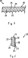
Vorrichtung (3, 13, 23) zum schneidenden und/oder spanenden Bearbeiten eines Objektes, aufweisend einen Bearbeitungskörper (2, 12, 22), welcher zumindest zwei Seitenflächen (1, 11, 21, 4, 14, 24) und mindestens eine die beiden Seitenflächen (1, 11, 21, 4, 14, 24) miteinander verbindende Schneide (5, 15, 25) umfasst, dadurch gekennzeichnet, dass zumindest in einem an die Schneide (5, 15, 25) angrenzenden Bereich an einer einzigen der beiden Seitenflächen (1, 11, 21, 4, 14, 24) eine reibungsmindernde Oberflächenstrukturierung (6, 16, 26) mittels eines Laserbehandlungsverfahrens angeordnet ist und dass an der anderen Seitenfläche (1, 11, 21, 4, 14, 24) erst in einem vorgebbaren Abstand (A) von der Schneide (5, 15, 25) zumindest teilweise eine reibungsmindernde Oberflächenstrukturierung (17) mittels eines Laserbehandlungsverfahrens angeordnet ist.Device (3, 13, 23) for cutting and / or machining an object, comprising a processing body (2, 12, 22), which has at least two side surfaces (1, 11, 21, 4, 14, 24) and at least one of Both side surfaces (1, 11, 21, 4, 14, 24) interconnecting blade (5, 15, 25), characterized in that at least in one of the cutting edge (5, 15, 25) adjacent to a single area both side surfaces (1, 11, 21, 4, 14, 24) a friction-reducing surface structuring (6, 16, 26) is arranged by means of a laser treatment process and that on the other side surface (1, 11, 21, 4, 14, 24) only at least partially a friction-reducing surface structuring (17) by means of a laser treatment process is arranged at a predetermined distance (A) from the cutting edge (5, 15, 25).
Description
Die Erfindung betrifft eine Vorrichtung zum schneidenden und/oder spanenden Bearbeiten eines Objektes, aufweisend einen Bearbeitungskörper, welcher zumindest zwei Seitenflächen und mindestens eine die beiden Seitenflächen miteinander verbindende Schneide umfasst.The invention relates to a device for cutting and / or machining an object, comprising a machining body, which comprises at least two side surfaces and at least one cutting edge connecting the two side surfaces.
Des Weiteren betrifft die Erfindung ein Verfahren zum Herstellen einer einen Bearbeitungskörper umfassenden Vorrichtung zum schneidenden und/oder spanenden Bearbeiten eines Objektes.Furthermore, the invention relates to a method for producing a device comprising a processing body for the cutting and / or machining of an object.
Vorrichtungen zum schneidenden und/oder spanenden Bearbeiten eines Objektes sind beispielsweise in Form von Messern und Sägen bekannt. Ein Messer weist einen eine Klinge ausbildenden Bearbeitungskörper auf, mit dem ein Objekt schneidend bearbeitet werden kann. Eine Säge weist einen ein Blatt ausbildenden Bearbeitungskörper auf, mit dem ein Objekt spanend bearbeitet werden kann.Devices for cutting and / or machining an object are known, for example, in the form of knives and saws. A knife has a blade forming a processing body, with which an object can be edited by cutting. A saw has a processing body forming a sheet with which an object can be machined.
Im Zusammenhang mit Messern ist es – wie beispielsweise aus
Aufgabe der Erfindung ist es, eine neue Vorrichtung zum schneidenden und/oder spanenden Bearbeiten eines Objektes bereitzustellen, deren Bearbeitungskörper eine selbsttätig schärfende Schneide aufweist und welche unter geringem Kraftaufwand handhabbar ist.The object of the invention is to provide a new device for cutting and / or machining an object whose processing body has an automatically sharpening edge and which can be handled with little effort.
Diese Aufgabe wird durch eine Vorrichtung gemäß Anspruch 1 und ein Verfahren gemäß Anspruch 7 gelöst. Vorteilhafte Ausgestaltungen sind in den Unteransprüchen angegeben, welche jeweils für sich genommen oder in verschiedener Kombination miteinander einen Aspekt der Erfindung darstellen können.This object is achieved by a device according to claim 1 and a method according to claim 7. Advantageous embodiments are specified in the subclaims, which taken alone or in different combination with each other can represent an aspect of the invention.
Mit Anspruch 1 wird eine Vorrichtung zum schneidenden und/oder spanenden Bearbeiten eines Objektes vorgeschlagen, aufweisend einen Bearbeitungskörper, welcher zumindest zwei Seitenflächen und mindestens eine die beiden Seitenflächen miteinander verbindende Schneide umfasst, dadurch gekennzeichnet, dass zumindest in einem an die Schneide angrenzenden Bereich an einer einzigen der beiden Seitenflächen eine reibungsmindernde Oberflächenstrukturierung mittels eines Laserbehandlungsverfahrens angeordnet ist und dass an der anderen Seitenfläche (
Durch die erfindungsgemäße Ausbildung der reibungsmindernden Beschichtung an einer einzigen Seitenfläche des Bearbeitungskörpers in einem an die Schneide angrenzenden Bereich dieser Seitenfläche mittels eines Laserbehandlungsverfahrens wird diese Seitenfläche bzw. die ihr zugeordnete Seite des Bearbeitungskörpers veredelt und gehärtet und weist daher eine größere Härte als die andere Seitenfläche des Bearbeitungskörpers auf. Bei einer Verwendung der erfindungsgemäßen Vorrichtung kommt es aufgrund dieses Härteunterschied zwischen den an die Schneide angrenzenden Seitenflächen des Bearbeitungskörpers zu einem stärkeren Materialabtrag an der nicht mit der reibungsmindernden Oberflächenstruktur versehenen Seitenfläche des Bearbeitungskörpers als an der mit der reibungsmindernden Oberflächenstrukturierung versehenen Seitenfläche des Bearbeitungskörpers. Hierdurch wird die Schneide des Bearbeitungskörpers bei Verwendung der erfindungsgemäßen Vorrichtung selbsttätig geschärft, so dass die Schneide über die Lebensdauer der Vorrichtung scharf bleibt.The inventive design of the friction-reducing coating on a single side surface of the machining body in a region adjacent to the cutting edge of this side surface by means of a laser treatment process, this side surface or its associated side of the processing body is finished and cured and therefore has a higher hardness than the other side surface of the Processing body on. When using the device according to the invention, due to this difference in hardness between the side surfaces of the processing body adjacent to the cutting edge, a greater material removal occurs on the side surface of the processing body not provided with the friction-reducing surface structure than on the side surface of the processing body provided with the friction-reducing surface structuring. As a result, the cutting edge of the processing body is automatically sharpened when using the device according to the invention, so that the cutting edge remains sharp over the life of the device.
Durch die reibungsmindernde Eigenschaft der Oberflächenstrukturierung treten bei einer Durchführung einer schneidenden und/oder spanenden Bearbeitung eines Objektes mittels der erfindungsgemäßen Vorrichtung geringere Reibungskräfte zwischen dem Bearbeitungskörper der Vorrichtung und dem Objekt auf.Due to the friction-reducing property of the surface structuring occur when performing a cutting and / or machining an object by means of the device according to the invention lower frictional forces between the processing body of the device and the object.
Als Laserbehandlungsverfahren kann beispielsweise ein Kaltlaser-Verfahren verwendet werden.As a laser treatment method, for example, a cold laser method can be used.
Gemäß einer vorteilhaften Ausgestaltung ist an der Seitenfläche, die mit der reibungsmindernden Oberflächenstrukturierung versehen ist, die reibungsmindernde Oberflächenstrukturierung vollflächig angeordnet und an der anderen Seitenfläche in einem vorgebbaren Abstand von der Schneide zumindest teilweise eine reibungsmindernde Oberflächenstrukturierung mittels eines Laserbehandlungsverfahrens angeordnet. Hierdurch können die bei einer Durchführung einer schneidenden und/oder spanenden Bearbeitung eines Objektes mittels der Vorrichtung zwischen dem Bearbeitungskörper der Vorrichtung und dem Objekt auftretenden Reibungskräfte weiter verringert werden, was den Kraftaufwand zur Handhabung der Vorrichtung weiter reduziert. Wichtig ist allerdings, dass die an der anderen Seitenfläche des Bearbeitungskörpers zumindest teilweise mittels eines Laserbehandlungsverfahrens angeordnete reibungsmindernde Oberflächenstrukturierung in einem vorgebbaren Abstand von der Schneide entfernt angeordnet ist, da ansonsten keine selbsttätige Schärfung der Schneide des Bearbeitungskörpers während der Verwendung der Vorrichtung auftritt. Die reibungsmindernden Oberflächenstrukturierungen der beiden Seitenflächen können sich in ihren Eigenschaften voneinander unterscheiden oder gleich aufgebaut sein.According to an advantageous embodiment, the friction-reducing surface structuring is arranged over the entire surface on the side surface, which is provided with the friction-reducing surface structuring, and at least partially a friction-reducing surface structuring by means of a laser treatment process is arranged on the other side surface at a predeterminable distance from the cutting edge. As a result, the frictional forces occurring when carrying out a cutting and / or machining of an object by means of the device between the processing body of the device and the object can be further reduced, which further reduces the force required to handle the device. It is important, however, that at least partially on the other side surface of the machining body arranged by means of a laser treatment process arranged friction-reducing surface structuring at a predeterminable distance from the cutting edge, otherwise there is no automatic sharpening of the cutting edge of the processing body during use of the device. The friction-reducing surface structuring of the two side surfaces may differ in their properties from each other or be constructed the same.
Vorteilhafterweise ist die reibungsmindernde Oberflächenstrukturierung eine wellenförmige Strukturierung. Die wellenförmige Strukturierung, auch Ripple-Strukturierung genannt, kann auf einfache Art und Weise beispielsweise mittels eines Femtosekundenlasers hergestellt werden. Als Strukturierung können unterschiedliche Ausführungsformen einer Ripple-Struktur, einer Riffle Struktur, einer Doppelripple-Struktur oder einer unterbrochenen Doppelripple-Struktur vorgesehen sein. Eine Doppelripple-Struktur kann v-förmig ausgebildet sein. Aber auch eine unterbrochene Doppelripple-Struktur oder eine einfache Ripple-Struktur kann v-förmig ausgestaltet sein. Die Strukturierung kann auch durch wenigstens zwei sich kreuzende, wellenförmig ausgebildete Unterstrukturen ausgebildet sein. Die wellenförmig ausgebildete Strukturierung kann eine Periode in einem Bereich von etwa 200 Nanometer bis etwa 1500 Nanometer, vorzugsweise von etwa 220 Nanometer, 690 Nanometer, 900 Nanometer oder 1400 Nanometer, aufweisen.Advantageously, the friction-reducing surface structuring is a wavy structuring. The wavy structuring, also called ripple structuring, can be produced in a simple manner, for example by means of a femtosecond laser. As structuring, different embodiments of a ripple structure, a riffle structure, a double ripple structure or an interrupted double ripple structure can be provided. A double ripple structure may be V-shaped. But even an interrupted double ripple structure or a simple ripple structure can be configured in a V-shape. The structuring can also be formed by at least two intersecting, wave-shaped substructures. The undulating pattern may have a period in a range of about 200 nanometers to about 1500 nanometers, preferably about 220 nanometers, 690 nanometers, 900 nanometers or 1400 nanometers.
Nach einer weiteren vorteilhaften Ausgestaltung ist wenigstens eine Seitenfläche zumindest teilweise durch eine an einem metallischen Grundkörper des Bearbeitungskörpers angeordnete, wenigstens einschichtig aufgebaute Beschichtung aus einem hochfesten keramischen Werkstoff ausgebildet. Die Beschichtung kann eine Schichtdicke von etwa 1 bis etwa 4 Mikrometer, vorzugsweise von etwa 1 bis etwa 1,5 Mikrometer, aufweisen. Die Beschichtung kann auch aus zwei oder mehreren Unterschichten gebildet sein, welche sich in ihren Eigenschaften voneinander unterscheiden oder gleich ausgebildet sein können. Solche Unterschichten können beispielsweise eine Schichtdicke von etwa 50 bis etwa 75 Nanometer aufweisen. Die Beschichtung kann auf ihrer dem metallischen Grundkörper abgewandten Seite beispielsweise einen Reibungskoeffizienten von etwa 0,05 bis etwa 0,2, vorzugsweise etwa 0,1, aufweisen.According to a further advantageous embodiment, at least one side surface is formed at least partially by a coating made of a high-strength ceramic material arranged on a metallic main body of the processing body and constructed at least in one layer. The coating may have a layer thickness of from about 1 to about 4 microns, preferably from about 1 to about 1.5 microns. The coating may also be formed from two or more sub-layers, which differ in their properties from each other or may be the same. Such sublayers may, for example, have a layer thickness of about 50 to about 75 nanometers. By way of example, the coating may have a coefficient of friction of about 0.05 to about 0.2, preferably about 0.1, on its side facing away from the metallic base body.
Vorzugsweise ist die Beschichtung zumindest teilweise aus Titannitrid, Titanaluminiumnitrid oder diamantähnlichem amorphem Kohlenstoff („Diamant Like Carbon”; DLC) gebildet. Die Beschichtung kann eine Härte zwischen etwa 2500 bis etwa 10000 HV (Vickershärte), vorzugsweise zwischen etwa 4000 bis etwa 5000 HV, und Reibwerte zwischen etwa 0,3 bis etwa 0,01 aufweisen. Der zur Ausbildung der Beschichtung verwendete Werkstoff kann mit unterschiedlichen Stoffen versetzt sein, um für den jeweiligen Anwendungsfall optimale Eigenschaften für den Bearbeitungskörper bzw. die Vorrichtung zu erzielen.Preferably, the coating is at least partially formed of titanium nitride, titanium aluminum nitride, or diamond-like amorphous carbon ("DLC"). The coating may have a hardness between about 2500 to about 10000 HV (Vickers hardness), preferably between about 4000 to about 5000 HV, and friction values between about 0.3 to about 0.01. The material used to form the coating can be mixed with different substances in order to achieve optimal properties for the respective application for the processing body or the device.
Vorteilhafterweise enthält die Beschichtung Silber. Das Silber kann in eine Unterschicht einer mehrschichtig angeordneten Beschichtung angeordnet sein, welche durch die Ausbildung der reibungsmindernden Oberflächenstrukturierung an dem Bearbeitungskörper zumindest teilweise freigelegt wird. Alternativ kann das Silber in einer am weitesten von dem metallischen Grundkörper entfernt angeordneten Unterschicht angeordnet sein. Die Einbringung von Silber in die Beschichtung ist mit einer antibakteriellen Wirkung verbunden.Advantageously, the coating contains silver. The silver may be disposed in an underlayer of a multilayer coating which is at least partially exposed by the formation of the friction reducing surface structuring on the processing body. Alternatively, the silver may be disposed in a sub-layer farthest from the metallic base. The incorporation of silver into the coating has an antibacterial effect.
Eine weitere vorteilhafte Ausgestaltung sieht vor, dass die Vorrichtung als Messer, Säge, Kanüle oder Bohrer ausgebildet ist. Mit einem Messer und einer Kanüle kann eine schneidende Bearbeitung eines Objektes und mit einer Säge und einem Bohrer eine spanende Bearbeitung eines Objektes durchgeführt werden.A further advantageous embodiment provides that the device is designed as a knife, saw, cannula or drill. With a knife and a cannula, a cutting processing of an object and with a saw and a drill a machining of an object can be performed.
Mit Anspruch 7 wird ein Verfahren zum Herstellen einer einen Bearbeitungskörper umfassenden Vorrichtung zum schneidenden und/oder spanenden Bearbeiten eines Objektes vorgeschlagen, aufweisend die Schritte:
- – Bereitstellen eines Bearbeitungskörpers, welcher zumindest zwei Seitenflächen und mindestens eine die beiden Seitenflächen miteinander verbindende Schneide umfasst;
- – Ausbilden einer reibungsmindernden Oberflächenstrukturierung zumindest in einem an die Schneide angrenzenden Bereich an einer einzigen der beiden Seitenflächen mittels eines Laserbehandlungsverfahrens.
- - Providing a processing body, which at least two side surfaces and at least one of the two side surfaces interconnecting edge comprises;
- - Forming a friction-reducing surface structuring at least in a region adjacent to the cutting edge on a single of the two side surfaces by means of a laser treatment process.
Mit diesem Verfahren sind die oben mit Bezug auf die Vorrichtung genannten Vorteile und Ausführungsvarianten entsprechend verbunden. Das Bereitstellen eines Bearbeitungskörpers kann eine Neuherstellung eines speziellen Bearbeitungskörpers umfassen. Alternativ kann das Bereitstellen eines Bearbeitungskörpers einen Rückgriff auf bereits vorhandene Vorrichtungen bzw. deren Bearbeitungskörper umfassen. Letzteres mach ein Verfahren zum Behandeln von bereits vorhandenen entsprechenden Vorrichtungen möglich.With this method, the advantages and variants mentioned above with regard to the device are connected accordingly. The provision of a processing body may include a re-manufacturing of a particular processing body. Alternatively, the provision of a processing body may involve a recourse to already existing devices or their processing bodies. The latter makes possible a method of treating already existing corresponding devices.
Gemäß einer vorteilhaften Ausgestaltung wird an der Seitenfläche, die mit der reibungsmindernden Oberflächenstrukturierung versehen wird, die reibungsmindernde Oberflächenstrukturierung vollflächig ausgebildet und an der anderen Seitenfläche in einem vorgebbaren Abstand von der Schneide zumindest teilweise eine reibungsmindernde Oberflächenstrukturierung mittels eines Laserbehandlungsverfahrens ausgebildet. Mit dieser Ausgestaltung sind die oben mit Bezug auf die entsprechende Ausgestaltung der Vorrichtung genannten Vorteile und Ausführungsvarianten entsprechend verbunden.According to an advantageous embodiment, the friction-reducing surface structuring is formed on the side surface, which is provided with the friction-reducing surface structuring over the entire surface and on the other side surface at a predetermined distance from the cutting edge at least partially a friction-reducing Surface structuring formed by means of a laser treatment process. With this embodiment, the advantages and design variants mentioned above with reference to the corresponding embodiment of the device are connected accordingly.
Vorteilhafterweise wird die reibungsmindernde Oberflächenstrukturierung als wellenförmige Strukturierung ausgebildet. Auch mit dieser Ausgestaltung sind die oben mit Bezug auf die entsprechende Ausgestaltung der Vorrichtung genannten Vorteile und Ausführungsvarianten entsprechend verbunden.Advantageously, the friction-reducing surface structuring is formed as a wave-shaped structuring. Also with this embodiment, the advantages and embodiments mentioned above with respect to the corresponding embodiment of the device are connected accordingly.
Nach einer weitere vorteilhaften Ausgestaltung wird zur Herstellung des Bearbeitungskörpers ein metallischer Grundkörper bereitgestellt, an dem zur Ausbildung von wenigstens einer Seitenfläche des Bearbeitungskörpers zumindest teilweise eine wenigstens einschichtig aufgebaute Beschichtung aus einem hochfesten keramischen Werkstoff angeordnet wird. Auch mit dieser Ausgestaltung sind die oben mit Bezug auf die entsprechende Ausgestaltung der Vorrichtung genannten Vorteile und Ausführungsvarianten entsprechend verbunden. Die Beschichtung kann an dem metallischen Grundkörper angeordnet und anschließend die Ausbildung der reibungsmindernden Oberflächenstrukturierung an der Beschichtung ausgebildet werden. Der metallische Grundkörper kann neu hergestellt sein oder durch einen Rückgriff auf bereits vorhandene Vorrichtungen bereitgestellt werden.According to a further advantageous embodiment, a metallic base body is provided for the production of the machining body, at least partially arranged to form at least one side surface of the machining body of at least one layer structure of a high-strength ceramic material. Also with this embodiment, the advantages and embodiments mentioned above with respect to the corresponding embodiment of the device are connected accordingly. The coating can be arranged on the metallic base body and subsequently the formation of the friction-reducing surface structuring on the coating can be formed. The metallic base body may be newly manufactured or provided by resorting to existing devices.
Vorzugsweise wird die Beschichtung zumindest teilweise aus Titannitrid, Titanaluminiumnitrid und/oder diamantähnlichem amorphem Kohlenstoff gebildet. Auch mit dieser Ausgestaltung sind die oben mit Bezug auf die entsprechende Ausgestaltung der Vorrichtung genannten Vorteile und Ausgestaltungsvarianten entsprechend verbunden.Preferably, the coating is at least partially formed of titanium nitride, titanium aluminum nitride and / or diamond-like amorphous carbon. Also with this embodiment, the advantages and design variants mentioned above with reference to the corresponding embodiment of the device are connected accordingly.
Vorteilhafterweise wird in die Beschichtung zumindest teilweise Silber eingebracht. Auch mit dieser Ausgestaltung sind die oben mit Bezug auf die entsprechende Ausgestaltung der Vorrichtung genannten Vorteile und Ausgestaltungsvarianten entsprechend verbunden.Advantageously, at least partially silver is introduced into the coating. Also with this embodiment, the advantages and design variants mentioned above with reference to the corresponding embodiment of the device are connected accordingly.
Eine weitere vorteilhafte Ausgestaltung sieht vor, dass die Beschichtung mittels eines PVD-, insbesondere PLD-, oder Sputter-Verfahrens an dem metallischen Grundkörper angeordnet wird.A further advantageous embodiment provides that the coating by means of a PVD, in particular PLD, or sputtering method is arranged on the metallic base body.
Im Folgenden wird die Erfindung unter Bezugnahme auf die anliegenden Figuren anhand von bevorzugten Ausführungsbeispielen exemplarisch erläutert, wobei die nachfolgend dargestellten Merkmale sowohl jeweils für sich genommen als auch in unterschiedlicher Kombination miteinander einen Aspekt der Erfindung darstellen können. Es zeigenIn the following, the invention will be explained by way of example with reference to the attached figures with reference to preferred exemplary embodiments, wherein the features illustrated below may represent an aspect of the invention both individually and in different combinations with one another. Show it
BezugszeichenlisteLIST OF REFERENCE NUMBERS
- 11
- Seitenflächeside surface
- 22
- Bearbeitungskörpertreating body
- 33
- Vorrichtungcontraption
- 44
- Seitenflächeside surface
- 55
- Schneidecutting edge
- 66
- Oberflächenstrukturierungsurface structuring
- 77
- Grundkörperbody
- 88th
- Beschichtungcoating
- 1111
- Seitenflächeside surface
- 1212
- Bearbeitungskörpertreating body
- 1313
- Vorrichtungcontraption
- 1414
- Seitenflächeside surface
- 1515
- Schneidecutting edge
- 1616
- Oberflächenstrukturierungsurface structuring
- 1717
- Oberflächenstrukturierungsurface structuring
- 2121
- Seitenflächeside surface
- 2222
- Bearbeitungskörpertreating body
- 2323
- Vorrichtungcontraption
- 2424
- Seitenflächeside surface
- 2525
- Schneidecutting edge
- 2626
- Oberflächenstrukturierungsurface structuring
- 2727
- Grundkörperbody
- 2828
- Beschichtungcoating
- AA
- Abstanddistance
Claims (12)
Priority Applications (1)
| Application Number | Priority Date | Filing Date | Title |
|---|---|---|---|
| DE102013114659.7A DE102013114659B4 (en) | 2013-12-20 | 2013-12-20 | Device for cutting and / or machining an object |
Applications Claiming Priority (1)
| Application Number | Priority Date | Filing Date | Title |
|---|---|---|---|
| DE102013114659.7A DE102013114659B4 (en) | 2013-12-20 | 2013-12-20 | Device for cutting and / or machining an object |
Publications (2)
| Publication Number | Publication Date |
|---|---|
| DE102013114659A1 DE102013114659A1 (en) | 2015-06-25 |
| DE102013114659B4 true DE102013114659B4 (en) | 2017-03-16 |
Family
ID=53275048
Family Applications (1)
| Application Number | Title | Priority Date | Filing Date |
|---|---|---|---|
| DE102013114659.7A Expired - Fee Related DE102013114659B4 (en) | 2013-12-20 | 2013-12-20 | Device for cutting and / or machining an object |
Country Status (1)
| Country | Link |
|---|---|
| DE (1) | DE102013114659B4 (en) |
Families Citing this family (4)
| Publication number | Priority date | Publication date | Assignee | Title |
|---|---|---|---|---|
| EP3115137A1 (en) * | 2015-07-07 | 2017-01-11 | ThyssenKrupp Metalúrgica Campo Limpo Ltda. | A machining tool |
| CN110315216B (en) * | 2018-03-29 | 2021-07-30 | 上海名古屋精密工具股份有限公司 | Method for laser machining a workpiece and use thereof for producing a tool |
| CN111593550B (en) * | 2020-06-12 | 2021-09-24 | 拓卡奔马机电科技有限公司 | Cut-off knife and cut-off bed for cut-off bed |
| PL4149732T3 (en) * | 2020-09-16 | 2024-11-04 | Philip Morris Products S.A. | Knife |
Citations (5)
| Publication number | Priority date | Publication date | Assignee | Title |
|---|---|---|---|---|
| EP0446811A1 (en) * | 1990-03-10 | 1991-09-18 | Onoda Cement Company, Ltd. | Method and apparatus for grinding diamond and diamond product using the same |
| DE19724319C1 (en) * | 1997-06-10 | 1998-10-08 | Fette Wilhelm Gmbh | Influencing characteristics of chip flow from tool surfaces |
| EP1537930A1 (en) * | 2003-12-04 | 2005-06-08 | WENDT GmbH | Cutting tool and process for finishing a cutting tool |
| DE102004047878A1 (en) * | 2004-10-01 | 2006-04-20 | Gardena Manufacturing Gmbh | hedge clippers |
| DE102010017625A1 (en) * | 2010-06-28 | 2011-12-29 | Bohle Ag | Cutting tool, in particular cutting wheel and method for its production |
-
2013
- 2013-12-20 DE DE102013114659.7A patent/DE102013114659B4/en not_active Expired - Fee Related
Patent Citations (5)
| Publication number | Priority date | Publication date | Assignee | Title |
|---|---|---|---|---|
| EP0446811A1 (en) * | 1990-03-10 | 1991-09-18 | Onoda Cement Company, Ltd. | Method and apparatus for grinding diamond and diamond product using the same |
| DE19724319C1 (en) * | 1997-06-10 | 1998-10-08 | Fette Wilhelm Gmbh | Influencing characteristics of chip flow from tool surfaces |
| EP1537930A1 (en) * | 2003-12-04 | 2005-06-08 | WENDT GmbH | Cutting tool and process for finishing a cutting tool |
| DE102004047878A1 (en) * | 2004-10-01 | 2006-04-20 | Gardena Manufacturing Gmbh | hedge clippers |
| DE102010017625A1 (en) * | 2010-06-28 | 2011-12-29 | Bohle Ag | Cutting tool, in particular cutting wheel and method for its production |
Also Published As
| Publication number | Publication date |
|---|---|
| DE102013114659A1 (en) | 2015-06-25 |
Similar Documents
| Publication | Publication Date | Title |
|---|---|---|
| DE3700250C2 (en) | ||
| DE102006001816B4 (en) | Saw blade with a base body and teeth with a cutting edge with a wear protection layer | |
| EP2484471B1 (en) | Machining tool | |
| EP2454043B1 (en) | Drill | |
| EP3530389B1 (en) | Milling tool | |
| DE112009000013T5 (en) | end mill | |
| DE102013114659B4 (en) | Device for cutting and / or machining an object | |
| DE3609251A1 (en) | TURNING INTERNAL KNIFE FOR AN ELECTRIC SHAVER AND MANUFACTURING METHOD THEREFOR | |
| EP3184073B1 (en) | Tool for the treatment of interdental surfaces | |
| DE102011076584A1 (en) | Cutting tool, useful for machining workpieces, comprises a base body that comprises cutting edges in a region of its free end, where the cutting edges extend radially outward starting from the center of the base body | |
| EP2682219A1 (en) | Method for workpiece processing | |
| EP3493937B1 (en) | Harvesting knife and method for the production thereof | |
| DE102014010791A1 (en) | Method for producing a surface electrode | |
| DE202009009800U1 (en) | Apparatus for creating a hole in a sheet material | |
| EP3974087A1 (en) | Milling tool and method for manufacturing such a milling tool | |
| AT15155U1 (en) | peeling plate | |
| DE102006034010A9 (en) | Saw tooth with hard coating | |
| AT404658B (en) | CUTTING BAR | |
| DE102012025040A1 (en) | Tool e.g. milling cutter for roughening metallic surface of workpiece for receiving thermal coating, has cutting edges that are formed as profiled cutting edges and are made to intersect over other | |
| DE102013106257A1 (en) | Component for an injection molding machine | |
| DE102011054677B4 (en) | Milling tool | |
| DE69020551T2 (en) | SURGICAL BLADES. | |
| DE102016214701B4 (en) | Hob and method of making a hob | |
| DE102018125464B4 (en) | Saw chain for working wood and plastic and method for manufacturing a saw link | |
| DE102018113912B3 (en) | Cutting device for producing an expandable root vegetable |
Legal Events
| Date | Code | Title | Description |
|---|---|---|---|
| R012 | Request for examination validly filed | ||
| R016 | Response to examination communication | ||
| R016 | Response to examination communication | ||
| R018 | Grant decision by examination section/examining division | ||
| R020 | Patent grant now final | ||
| R119 | Application deemed withdrawn, or ip right lapsed, due to non-payment of renewal fee |