DE102013102401B4 - vehicle seat adjustment - Google Patents
vehicle seat adjustment Download PDFInfo
- Publication number
- DE102013102401B4 DE102013102401B4 DE102013102401.7A DE102013102401A DE102013102401B4 DE 102013102401 B4 DE102013102401 B4 DE 102013102401B4 DE 102013102401 A DE102013102401 A DE 102013102401A DE 102013102401 B4 DE102013102401 B4 DE 102013102401B4
- Authority
- DE
- Germany
- Prior art keywords
- seat
- function
- polynomial
- angular velocity
- circuit
- Prior art date
- Legal status (The legal status is an assumption and is not a legal conclusion. Google has not performed a legal analysis and makes no representation as to the accuracy of the status listed.)
- Active
Links
Images


Classifications
-
- G—PHYSICS
- G05—CONTROLLING; REGULATING
- G05B—CONTROL OR REGULATING SYSTEMS IN GENERAL; FUNCTIONAL ELEMENTS OF SUCH SYSTEMS; MONITORING OR TESTING ARRANGEMENTS FOR SUCH SYSTEMS OR ELEMENTS
- G05B19/00—Programme-control systems
- G05B19/02—Programme-control systems electric
- G05B19/18—Numerical control [NC], i.e. automatically operating machines, in particular machine tools, e.g. in a manufacturing environment, so as to execute positioning, movement or co-ordinated operations by means of programme data in numerical form
- G05B19/19—Numerical control [NC], i.e. automatically operating machines, in particular machine tools, e.g. in a manufacturing environment, so as to execute positioning, movement or co-ordinated operations by means of programme data in numerical form characterised by positioning or contouring control systems, e.g. to control position from one programmed point to another or to control movement along a programmed continuous path
-
- B—PERFORMING OPERATIONS; TRANSPORTING
- B60—VEHICLES IN GENERAL
- B60N—SEATS SPECIALLY ADAPTED FOR VEHICLES; VEHICLE PASSENGER ACCOMMODATION NOT OTHERWISE PROVIDED FOR
- B60N2/00—Seats specially adapted for vehicles; Arrangement or mounting of seats in vehicles
- B60N2/02—Seats specially adapted for vehicles; Arrangement or mounting of seats in vehicles the seat or part thereof being movable, e.g. adjustable
- B60N2/0224—Non-manual adjustments, e.g. with electrical operation
- B60N2/0244—Non-manual adjustments, e.g. with electrical operation with logic circuits
- B60N2/0272—Non-manual adjustments, e.g. with electrical operation with logic circuits using sensors or detectors for detecting the position of seat parts
-
- G—PHYSICS
- G05—CONTROLLING; REGULATING
- G05B—CONTROL OR REGULATING SYSTEMS IN GENERAL; FUNCTIONAL ELEMENTS OF SUCH SYSTEMS; MONITORING OR TESTING ARRANGEMENTS FOR SUCH SYSTEMS OR ELEMENTS
- G05B2219/00—Program-control systems
- G05B2219/30—Nc systems
- G05B2219/45—Nc applications
- G05B2219/45022—Auto seat, dentist chair, roll wheel chair
Landscapes
- Engineering & Computer Science (AREA)
- Human Computer Interaction (AREA)
- Manufacturing & Machinery (AREA)
- Physics & Mathematics (AREA)
- General Physics & Mathematics (AREA)
- Automation & Control Theory (AREA)
- Aviation & Aerospace Engineering (AREA)
- Transportation (AREA)
- Mechanical Engineering (AREA)
- Seats For Vehicles (AREA)
Abstract
Schaltung (1; 1'; 1") zum Ansteuern eines Elektromotors zur Lehnenneigungseinstellung abhängig von einer Sitzneigungseinstellung einer Sitzeinheit, die für eine elektromotorische Sitzneigungseinstellung und eine elektromotorische Lehnenneigungseinstellung konfiguriert ist, mittels eines Ansteuersignals (z), wobei die Schaltung Folgendes aufweist:einen Eingang (11; 11'; 11") zum Empfangen eines ersten und eines zweiten Positionssignals (x, y),einen Speicher (13), in welchem Polynomialkoeffizienten pckgespeichert sind,einen Prozessor (12; 12'; 12"), welcher an den Eingang (11; 11'; 11") und an den Speicher (13) gekoppelt ist,wobei der Prozessor (12; 12'; 12") dafür eingerichtet ist, das Ansteuersignal z als Polynomialfunktion der empfangenen Positionssignale (x, y) mittels der in dem Speicher (13) gespeicherten Polynomialkoeffizienten pckzu bestimmen,wobei die Polynomialfunktion mit den Polynomialkoeffizienten pckeine Annäherung an eine Funktion F der Positionssignale (x, y) bildet, wobei die Annäherung einer ersten polynomialen Regression der Funktion F in Abhängigkeit des ersten Positionssignals x entspricht, deren Koeffizienten durch eine zweite polynomiale Regression in Abhängigkeit des zweiten Positionssignals (y) angenähert sind,wobei die Schaltung (1") ferner eine Ansteuereinheit (15) für einen Elektromotor umfasst, welche zum Empfangen des Ansteuersignals an den Prozessor (12") gekoppelt ist und dafür eingerichtet ist, eine Sollwinkelgeschwindigkeit des Elektromotors abhängig von dem Ansteuersignal einzustellen, wobei die Abhängigkeit der Sollwinkelgeschwindigkeit des Elektromotors von dem Ansteuersignal eine lineare Abhängigkeit ist,wobei in der Schaltung ferner eine Eingangswinkelgeschwindigkeit gespeichert ist oder wobei die Ansteuereinheit (15) dafür eingerichtet ist, eine Eingangswinkelgeschwindigkeit zu empfangen und die Sollwinkelgeschwindigkeit des Elektromotors zur Lehnenneigungseinstellung ferner abhängig von der gespeicherten bzw. empfangenen Eingangswinkelgeschwindigkeit einzustellen.Circuit (1; 1'; 1") for driving an electric motor for adjusting the backrest angle depending on a seat angle adjustment of a seat unit configured for an electromotive seat angle adjustment and an electromotive backrest angle adjustment, by means of a control signal (z), the circuit having the following:an input (11; 11'; 11") for receiving a first and a second position signal (x, y), a memory (13) in which polynomial coefficients pck are stored, a processor (12; 12'; 12") connected to the input (11; 11'; 11") and coupled to the memory (13), wherein the processor (12; 12'; 12") is set up to process the control signal z as a polynomial function of the received position signals (x, y) by means of the polynomial coefficients pck stored in the memory (13), the polynomial function with the polynomial coefficients pc forming no approximation to a function F of the position signals (x, y), wobe i corresponds to the approximation of a first polynomial regression of the function F as a function of the first position signal x, the coefficients of which are approximated by a second polynomial regression as a function of the second position signal (y), the circuit (1") also having a control unit (15) for comprises an electric motor which is coupled to the processor (12") to receive the control signal and is set up to set a target angular velocity of the electric motor as a function of the control signal, the dependency of the target angular velocity of the electric motor on the control signal being a linear dependency, wherein in an input angular velocity is also stored in the circuit or wherein the control unit (15) is set up to receive an input angular velocity and the setpoint angular velocity of the electric motor for adjusting the backrest angle is also dependent on the stored or received input set angular velocity.
Description
Die Erfindung betrifft eine Schaltung, eine elektromotorische Einheit, eine Sitzeinheit sowie ein Verfahren und ein Speichermedium zum Ansteuern eines Elektromotors, insbesondere zum Verstellen eines Sitzes, zum Beispiel eines Fahrzeugsitzes.The invention relates to a circuit, an electromotive unit, a seat unit and a method and a storage medium for controlling an electric motor, in particular for adjusting a seat, for example a vehicle seat.
Fahrer- und Beifahrersitz eines PKW verfügen in der Regel über mehrere Achsen, mittels welcher Bereiche des Sitzes über Elektromotoren verstellt werden können. So können üblicherweise die Sitzhöheneinstellung SHE, die Sitzneigungseinstellung SNE sowie die Lehnenneigungseinstellung LNE angepasst werden, indem ein Sitzhöhenwinkel φHE, ein Sitzneigungswinkel φSNE bzw. ein Sitzkissenwinkel φSK mittels der Elektromotoren verändert werden. Der schematische Aufbau eines Sitzes mit den genannten Winkeln ist in
Weiterer Stand der Technik ist aus der
Der Sitz weist dabei eine Sitzkissenauflage auf, welche sich entlang der mit f dargestellten Linie erstreckt. Die Sitzkissenauflage schließt mit einer Längsachse des Fahrzeugs einen Sitzkissenwinkel φSK ein. Der Sitz ist an mehreren Punkten fest mit dem Fahrzeugchassis verbunden.The seat has a seat cushion support which extends along the line shown with f. The seat cushion cover encloses a seat cushion angle φ SK with a longitudinal axis of the vehicle. The seat is firmly connected to the vehicle chassis at several points.
Nachteilig an der gezeigten Konstruktion ist, dass ein Verstellen des Sitzhöhenwinkels φHE durch die mechanische Kopplung auch den Sitzkissenwinkel φSK verändert. Die Kopplung ist, wie in der
Da diese Veränderung des Sitzkissenwinkels φSK vom Fahrer in der Regel nicht gewünscht ist, muss dieser Effekt durch eine Veränderung des Lehnenwinkels, der an den Sitzkissenwinkel gekoppelt ist, kompensiert werden.Since this change in the seat cushion angle φ SK is generally not desired by the driver, this effect must be compensated for by changing the backrest angle, which is linked to the seat cushion angle.
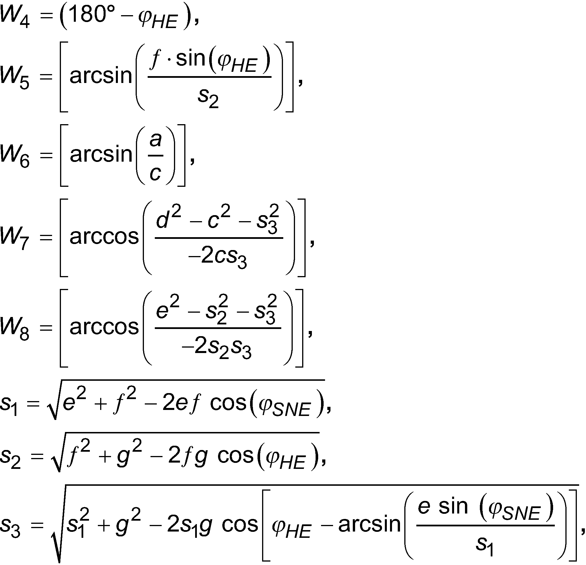
Es ist daher wünschenswert, dass der Elektromotor, welcher die Lehnenneigung einstellt, automatisch betätigt wird, wenn die Sitzneigung vom Fahrer verstellt wird, um die absolute Lehnenneigung relativ zur Fahrkabine konstant zu halten. Die zur optimalen Kompensation erforderliche Sollwinkelgeschwindigkeit nLNE für die Lehnenneigungsverstellung hängt dabei von dem aktuellen Sitzneigungswinkel φSNE, dem aktuellen Sitzhöhenwinkel φHE sowie der Winkelgeschwindigkeit nSNE, mit welcher der Sitzneigungswinkel φSNE verändert wird, ab:![]()
![]()
Dabei lässt sich der Ausdruck (1) vereinfachen zu:![]()
![]()
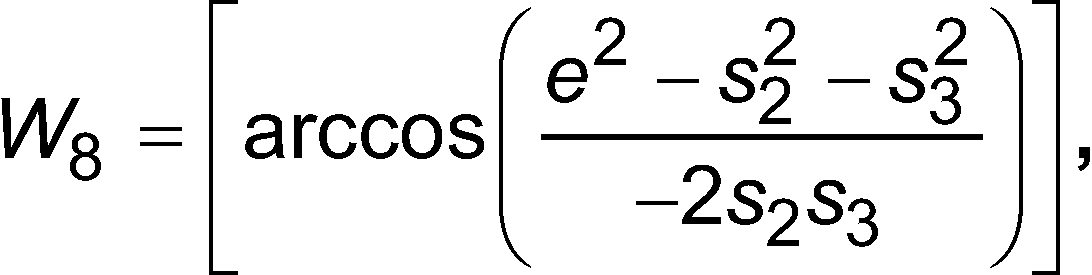
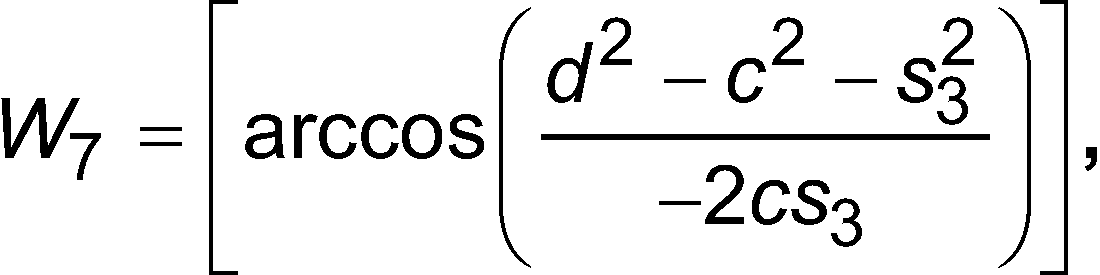
Die Funktion F entspricht dabei der ersten partiellen Ableitung des Sitzkissenwinkels φSK nach dem Sitzneigungswinkel φSNE. Gemäß der ![]()
- a :
- die Höhe einer Unterkante einer Vorderseite des Sitzes relativ zu einem Untergrund,
- c :
- die Länge einer Bodenseite des Sitzes, von der Unterkante der Vorderseite bis zu einem Auflagepunkt des Sitzes auf dem Untergrund gemessen,
- b :
- der Anteil in horizontaler Richtung der Länge c,
- d :
- die Länge einer ersten Vorderkante des Sitzes,
- e :
- die Länge einer zweiten Vorderkante des Sitzes,
- f:
- die Länge einer Sitzfläche des Sitzes und
- g :
- die Länge einer hinteren Kante des Sitzes, vom Auflagepunkt bis zu einem Drehpunkt (D2) gemessen.
- a :
- the height of a lower edge of a front of the seat relative to a ground,
- c :
- is the length of a floor side of the seat, measured from the lower edge of the front side to a point where the seat rests on the ground,
- b :
- the proportion in the horizontal direction of the length c,
- d :
- the length of a first front edge of the seat,
- e :
- the length of a second front edge of the seat,
- f:
- the length of a seat surface of the seat and
- g :
- the length of a rear edge of the seat, measured from the support point to a pivot point (D2).
Der Verlauf der Funktion (3) ist in
Die optimale Ansteuerung der Lehnenneigungsverstellung ergibt sich somit als komplizierte Funktion F der beiden Winkel φHE und φSNE, so dass eine exakte Berechnung des erforderlichen Ansteuersignals, d.h. der optimalen Sollwinkelgeschwindigkeit nLNE der Lehnenneigungsverstellung, nur unter großem rechentechnischen Aufwand möglich ist. Um dies in Echtzeit, d. h. ohne eine für den Benutzer spürbare und möglicherweise störende Verzögerung durchzuführen, ist für die Auswertung der Ausdrücke (3) und (4) ein leistungsfähiger und somit verbrauchsintensiver und teurer Mikroprozessor erforderlich.The optimal control of the backrest inclination adjustment is thus obtained as a complicated function F of the two angles φ HE and φ SNE , so that an exact calculation of the required control signal, ie the optimal setpoint angular velocity n LNE of the backrest inclination adjustment, is only possible with great computational effort. In order to do this in real time, ie without a delay that is noticeable to the user and possibly disturbing, a powerful and therefore consumption-intensive and expensive microprocessor is required for the evaluation of expressions (3) and (4).
Es ist daher die Aufgabe der Erfindung, eine Ansteuerung des der Lehnenneigungseinstellung zugeordneten Elektromotors zu ermöglichen, durch welche ein Einfluss der Sitzneigungsverstellung auf die absolute Lehnenneigung praktisch verzögerungsfrei und ohne zusätzliche Hardware kompensiert wird.It is therefore the object of the invention to enable control of the electric motor associated with the backrest inclination adjustment, by means of which an influence of the seat inclination adjustment on the absolute backrest inclination is compensated for practically without delay and without additional hardware.
Die Aufgabe wird durch eine Schaltung gemäß Anspruch 1, eine elektromotorische Einheit gemäß Anspruch 7, eine Sitzeinheit gemäß Anspruch 8, ein Verfahren gemäß Anspruch 11 sowie ein Speichermedium gemäß Anspruch 16 gelöst.The object is achieved by a circuit according to
Die Erfindung stellt in einem ersten Aspekt eine Schaltung zum Ansteuern eines Elektromotors mittels eines Ansteuersignals z bereit, wobei die Schaltung einen Eingang zum Empfangen eines ersten und eines zweiten Positionssignals x, y aufweist. Die Schaltung weist ferner einen Speicher, in welchem Polynomialkoeffizienten pck gespeichert sind, und einen Prozessor, welcher an den Eingang und an den Speicher gekoppelt ist, auf. Der Prozessor ist dafür eingerichtet, das Ansteuersignal z als Polynomialfunktion der empfangenen Positionssignale x, y mittels der in dem Speicher gespeicherten Polynomialkoeffizienten pck zu bestimmen. Die Polynomialfunktion mit den Polynomialkoeffizienten pck bildet dabei eine Annäherung an eine Funktion F der Positionssignale x, y, wobei die Annäherung einer ersten polynomialen Regression der Funktion F in Abhängigkeit des ersten Positionssignals x entspricht, deren Koeffizienten durch eine zweite polynomiale Regression in Abhängigkeit des zweiten Positionssignals y angenähert sind.In a first aspect, the invention provides a circuit for driving an electric motor by means of a drive signal z, the circuit having an input for receiving a first and a second position signal x, y. The circuit further includes a memory in which polynomial coefficients p ck are stored and a processor coupled to the input and to the memory. The processor is set up to determine the control signal z as a polynomial function of the received position signals x, y using the polynomial coefficients p ck stored in the memory. The polynomial function with the polynomial coefficients p ck forms an approximation to a function F of the position signals x, y, with the approximation corresponding to a first polynomial regression of the function F as a function of the first position signal x, whose coefficients are determined by a second polynomial regression as a function of the second Position signal y are approximated.
Das Signal z kann dabei in der Form![]()
![]()
Durch die Schaltung kann somit ein Elektromotor zum Einstellen der Lehnenneigung angesteuert werden, indem der Prozessor der Schaltung lediglich ein Polynom zweier Positionssignale x, y berechnet. Mit Bezug auf
Gegenüber anderen Näherungsverfahren wie beispielsweise der Taylor-Näherung bietet die erfindungsgemäße Schaltung den Vorteil, dass die Näherung nicht nur eine Approximation in einem engen Bereich um einen einzelnen Aufpunkt darstellt. Vielmehr werden bei den Regressionen die gesamten relevanten Wertebereiche der Positionssignale berücksichtigt. Somit wird eine optimale Kompensation auch bei extremen Sitzeinstellungen ermöglicht.Compared to other approximation methods such as the Taylor approximation, the circuit according to the invention offers the advantage that the approximation does not only represent an approximation in a narrow range around a single reference point. Rather, the entire relevant value ranges of the position signals are taken into account in the regressions. This enables optimal compensation even with extreme seat adjustments.
Der Speicher kann als nicht flüchtiger Speicher ausgebildet sein. In einer Ausführungsform kann der Speicher einen Flash-Speicher, ein EPROM und/oder ein EEPROM aufweisen. In einigen Ausführungsformen sind die Polynomialkoeffizienten mittels Widerständen oder Kondensatoren fest in dem Speicher programmiert. Der Speicher kann über den Eingang der Schaltung und/oder über eine separate Verbindung programmierbar sein. Dies ist insbesondere vorteilhaft, wenn die gleiche Schaltung für verschiedene Sitze mit unterschiedlichen Abmessungen eingesetzt werden soll.The memory can be in the form of a non-volatile memory. In one embodiment, the memory may include flash memory, EPROM, and/or EEPROM. In some embodiments, the polynomial coefficients are hard-coded into memory using resistors or capacitors. The memory can be programmable via the input of the circuit and/or via a separate connection. This is particularly advantageous if the same circuit is to be used for different seats with different dimensions.
Die Positionssignale x, y beziehen sich in einigen Ausführungsformen auf eine Winkelposition einer ersten bzw. zweiten Achse. In anderen Ausführungsformen können sich die Positionssignale x, y auf eine lineare Position, beispielsweise eine Position entlang einer Achse beziehen. Auch wenn die Erfindung mit Hilfe von Winkeln φHE und φSNE beschrieben ist, wird der Fachmann erkennen, dass die erfindungsgemäße Kompensation auch erreicht wird, wenn andere Definitionen der Winkel oder sogar lineare Größen wie beispielsweise eine absolute Höhe der Sitzvorderkante oder einer Sitzmitte als Positionssignale verwendet werden.In some embodiments, the position signals x, y relate to an angular position of a first or second axis. In other embodiments, the position signals x, y can relate to a linear position, for example a position along an axis. Even if the invention is described using angles φ HE and φ SNE , those skilled in the art will recognize that the compensation according to the invention is also achieved when other definitions of the angles or even linear quantities such as an absolute height of the seat front edge or a seat center are used as position signals be used.
Die erste und/oder zweite polynomiale Regression kann zum Beispiel mittels eines Least-Square-Verfahrens durchgeführt sein. Die erste und/oder zweite Regression kann beispielsweise eine lineare Regression sein. Es ist jedoch bevorzugt, dass die erste und die zweite Regression jeweils Terme zweiter Ordnung berücksichtigen, um eine bessere Annäherung an die Funktion F zu erreichen. Ferner ist die Auswertung eines Polynoms, welches Terme zweiter Ordnung berücksichtigt, nicht besonders aufwendig, so dass sie von einem kostengünstigen und energiesparenden Mikroprozessor, beispielsweise einem 8bit-Mikroprozessor, ohne merkliche Verzögerung ausgeführt werden kann. Ferner müssen nur wenige Polynomialkoeffizienten gespeichert werden, so dass der Speicher der Schaltung klein dimensioniert sein kann. Es ist daher bevorzugt, dass der Prozessor beim Bestimmen des Ansteuersignals z das erste und/oder das zweite Positionssignal x, y bis zu Termen zweiter Ordnung berücksichtigt. Andere erfindungsgemäße Ausführungsformen, bei welchen auch Terme höherer Ordnung, insbesondere Terme bis zu dritter Ordnung oder Terme bis zu vierter Ordnung, berücksichtigt werden, bieten hingegen eine bessere Annäherung an die Funktion F.The first and/or second polynomial regression can be carried out using a least squares method, for example. The first and/or second regression can be a linear regression, for example. However, it is preferred that the first and the second regression each consider second-order terms in order to achieve a better approximation of the function F. Furthermore, the evaluation of a polynomial that takes second-order terms into account is not particularly complicated, so that it can be carried out by an inexpensive and energy-saving microprocessor, for example an 8-bit microprocessor, without any noticeable delay. Furthermore, only a few polynomial coefficients have to be stored, so that the memory of the circuit can have small dimensions. It is therefore preferred that the processor, when determining the control signal z, takes into account the first and/or the second position signal x, y up to terms of the second order. On the other hand, other embodiments according to the invention, in which terms of a higher order, in particular terms of up to third order or terms of up to fourth order, are also taken into account, offer a better approximation of the function F.
Gemäß einer bevorzugten Ausführungsform ist der Eingang dafür eingerichtet, um das erste und zweite Positionssignal x, y über einen Bus, insbesondere einen LIN-Bus zu empfangen. Ein Bus, insbesondere ein LIN-Bus stellt dabei ein kostengünstiges und einfaches Medium bereit, um die benötigten Positionssignale zu übertragen. Es kann vorgesehen sein, dass der Eingang der Schaltung mit einer Buchse oder einem Stecker versehen ist. In einigen Ausführungsformen weist der Eingang einen ersten und einen zweiten Sub-Eingang zum Empfangen des ersten bzw. zweiten Positionssignals auf. Dies ermöglicht ein gleichzeitiges Empfangen beider Positionssignale.According to a preferred embodiment, the input is set up to receive the first and second position signal x, y via a bus, in particular a LIN bus. A bus, in particular a LIN bus, provides an inexpensive and simple medium for transmitting the required position signals. It can be provided that the input of the circuit is provided with a socket or a plug. In some embodiments, the input has a first and a second sub-input for receiving the first and second position signals, respectively. This enables both position signals to be received simultaneously.
Gemäß einer bevorzugten Ausführungsform ist die Funktion F definiert durch die partielle Ableitung F = ∂φSK /∂φSNE folgender Funktion, wobei φHE und φSNE den Positionssignalen x, y entsprechen: 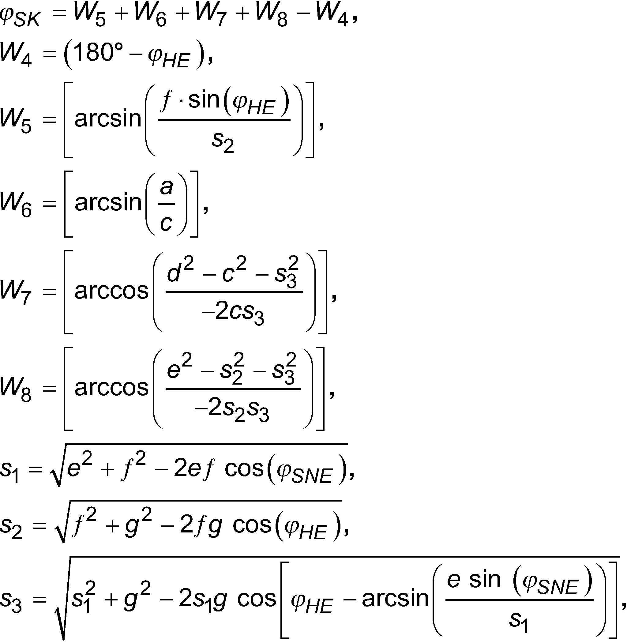
Gemäß einer bevorzugten Ausführungsform ergibt die erste polynomiale Regression der Funktion F in Abhängigkeit des ersten Positionssignals x eine Polynomfunktion![]()
![]()
![]()
![]()
Um zu einer Näherung zu gelangen, werden also zunächst n Stützstellen in y-Richtung definiert wie in
Hierzu kann der Verlauf der Koeffizienten bic über die n Stützstellen in y-Richtung hinweg ebenfalls jeweils durch ein Polynom angenähert werden. Um diese Näherung durchzuführen, werden Koeffizientenfunktionen v-ter Ordnung gemäß Gleichung (7) mit Koeffizienten pck als Annäherung für die Koeffizienten bic definiert. Um zu den Koeffizienten pck zu gelangen, wird eine zweite Regression für jeden der 1+1 Koeffizienten bic in Abhängigkeit von i durchgeführt. Die sich ergebenden Koeffizienten pck werden in einem Speicher abgelegt, wo sie für einen Abruf zur Ansteuerung der Sitzverstellung zur Verfügung stehen.For this purpose, the progression of the coefficients b ic across the n support points in the y-direction can also be approximated by a polynomial. To perform this approximation, v-th order coefficient functions are defined according to equation (7) with coefficients p ck as an approximation for the coefficients b ic . To arrive at the p ck coefficients, a second regression is performed for each of the 1+1 b ic coefficients as a function of i. The resulting coefficients p ck are stored in a memory where they are available for retrieval to control the seat adjustment.
In einer Ausführungform erfolgt die erste Regression in Abhängigkeit der Sitzhöheneinstellung und die zweite Regression in Abhängigkeit der Sitzneigungseinstellung, während in einer weiteren Ausführungsform die erste Regression in Abhängigkeit der Sitzneigungseinstellung und die zweite Regression in Abhängigkeit der Sitzhöheneinstellung erfolgt. Die Winkel der Sitzneigungseinstellung φSNE und der Sitzhöheneinstellung φHE können prinzipiell in einem Bereich von 0° bis 90° liegen. Die tatsächlich möglichen Werte können durch die konkrete Ausgestaltung der Sitzmechanik weiter eingeschränkt werden. In typischen Ausführungsbeispiel kann die Sitzneigungseinstellung φSNE auf einen Bereich zwischen 10° und 80° und die Sitzhöheneinstellung φHE auf einen Bereich von 15° bis 65° begrenzt sein.In one embodiment, the first regression takes place as a function of the seat height setting and the second regression as a function of the seat angle setting, while in a further embodiment the first regression takes place as a function of the seat angle setting and the second regression as a function of the seat height setting. In principle, the angles of the seat inclination adjustment φ SNE and the seat height adjustment φ HE can be in a range from 0° to 90°. The actually possible values can be further limited by the specific design of the seat mechanism. In typical exemplary embodiments, the seat inclination adjustment φ SNE can be limited to a range between 10° and 80° and the seat height adjustment φ HE to a range from 15° to 65°.
Zur Programmierung der erfindungsgemäßen Schaltung werden die beschriebenen ersten und zweiten Regressionen durchgeführt und in einigen Ausführungsformen die resultierenden Koeffizienten pck in dem Speicher der Schaltung gespeichert. Es sind aber auch Ausführungsformen der Erfindung möglich, bei denen aus den Koeffizienten pck abgeleitete Größen gespeichert werden. Die Anzahl der Koeffizienten pck ist dabei durch die Ordnungen 1 und v der ersten und zweiten Regression bestimmt.To program the circuit according to the invention, the first and second regressions described are carried out and, in some embodiments, the resulting coefficients p ck are stored in the memory of the circuit. However, embodiments of the invention are also possible in which quantities derived from the coefficients p ck are stored. The number of coefficients p ck is determined by the
Während des Betriebs wird sodann die Polynomialfunktion basierend auf den empfangenen Positionssignalen mit den Koeffizienten pck ausgewertet. Die Anzahl der zur Auswertung der Polynomialfunktion erforderlichen Multiplikationsvorgänge ist ebenfalls durch die Ordnungen 1 und v der ersten und zweiten Regression vorgegeben und kann beispielsweise für Regressionen zweiter Ordnungen (1=2, v=2) von einem herkömmlichen 8bit-Mikrokontroller annähernd in Echtzeit durchgeführt werden, so dass die auftretenden Verzögerungen bei der Ansteuerung des Elektromotors nicht spürbar sind. Die Schaltung kann dafür eingerichtet sein, das Ansteuersignal innerhalb von weniger als 50 ms, insbesondere weniger als 30 ms und bevorzugt weniger als 10 ms nach dem Empfangen der Positionssignale zu bestimmen.During operation, the polynomial function is then evaluated based on the received position signals with the coefficients p ck . The number of multiplication processes required to evaluate the polynomial function is also specified by the
Gemäß einer bevorzugten Ausführungsform umfasst die Schaltung ferner eine Ansteuereinheit für einen Elektromotor, welche zum Empfangen des Ansteuersignals an den Prozessor gekoppelt ist und eingerichtet ist, eine Sollwinkelgeschwindigkeit des Elektromotors abhängig, insbesondere linear abhängig, von dem Ansteuersignal einzustellen. In dieser Ausführungsform kann der Elektromotor direkt von der Schaltung angesteuert werden, ohne dass es hier zu einer weiteren Leistungsstufe bedarf. Dies ermöglicht einen kompakten und kostengünstigen Aufbau.According to a preferred embodiment, the circuit also includes a control unit for an electric motor, which is coupled to the processor to receive the control signal and is set up to set a setpoint angular velocity of the electric motor as a function, in particular as a linear function, of the control signal. In this embodiment, the electric motor can be controlled directly by the circuit without the need for a further power stage. This enables a compact and inexpensive construction.
Da die optimale Sollwinkelgeschwindigkeit nLNE gemäß Gleichung (2) linear von der aktuellen Winkelgeschwindigkeit nSNE der Sitzneigungseinstellung abhängt, kann in der Schaltung ferner eine Normwinkelgeschwindigkeit nSNE gespeichert sein, wobei die Ansteuereinheit die Sollwinkelgeschwindigkeit nLNE des Elektromotors linear abhängig von der gespeicherten Normwinkelgeschwindigkeit nSNE einstellt. Dies ist insbesondere dann vorteilhaft, wenn die Winkelgeschwindigkeit nSNE der Sitzneigungseinstellung im Betrieb nicht wesentlich von dem Normwert abweicht. In dieser Ausführungsform kann daher auf eine Übertragung der Winkelgeschwindigkeit nSNE verzichtet werden, wodurch der Verdrahtungsaufwand reduziert und der Schaltungsaufbau vereinfacht wird.Since the optimal target angular velocity n LNE according to equation (2) depends linearly on the current angular velocity n SNE of the seat inclination setting, a standard angular velocity n SNE can also be stored in the circuit, with the control unit linearly determining the target angular velocity n LNE of the electric motor as a function of the stored standard angular velocity n SNE set. This is particularly advantageous when the angular velocity n SNE of the seat inclination adjustment during operation does not deviate significantly from the standard value. In this embodiment, the angular velocity n SNE therefore does not need to be transmitted, which reduces the amount of wiring and simplifies the circuit design.
Es ist allerdings bevorzugt, dass die Ansteuereinheit ferner eingerichtet ist, eine Eingangswinkelgeschwindigkeit zu empfangen und die Sollwinkelgeschwindigkeit des Elektromotors linear abhängig von der Eingangswinkelgeschwindigkeit einzustellen. Diese Ausführungsform ermöglicht es, dass die Schaltung den Elektromotor optimal in Abhängigkeit der tatsächlichen Winkelgeschwindigkeit nSNE ansteuert. Die Ansteuereinheit kann insbesondere dafür eingerichtet sein, die Eingangswinkelgeschwindigkeit an dem Eingang der Schaltung zu empfangen.However, it is preferred that the control unit is also set up to receive an input angular velocity and to set the target angular velocity of the electric motor in a linear manner as a function of the input angular velocity. This embodiment makes it possible for the circuit to optimally control the electric motor as a function of the actual angular velocity n SNE . In particular, the control unit can be set up to receive the input angular velocity at the input of the circuit.
In einem weiteren Aspekt stellt die Erfindung eine elektromotorische Einheit für einen Sitz, insbesondere für einen Fahrzeugsitz bereit, welche eine Schaltung der beschriebenen Art sowie einen Elektromotor umfasst, wobei der Elektromotor an einen Ausgang der Ansteuereinheit der Schaltung gekoppelt ist. Dies ermöglicht eine platzsparende, kompakte und stabile Anordnung der Bauelemente. Die elektromotorische Einheit kann insbesondere zum Einstellen einer Lehnenneigung eines Fahrzeugsitzes eingerichtet sein.In a further aspect, the invention provides an electromotive unit for a seat, in particular for a vehicle seat, which comprises a circuit of the type described and an electric motor, the electric motor being coupled to an output of the control unit of the circuit. This enables a space-saving, compact and stable arrangement of the components. The electromotive unit can be set up in particular for adjusting a backrest inclination of a vehicle seat.
Gemäß einem weiteren Aspekt stellt die Erfindung eine Sitzeinheit mit einem verstellbaren Sitz, insbesondere einem verstellbaren Fahrzeugsitz, und der beschriebenen elektromotorischen Einheit bereit, wobei die elektromotorische Einheit dazu eingerichtet ist, den Sitz zu verstellen und wobei der Eingang der Schaltung mit zumindest einem Sensor zur Erfassung einer Sitzposition des Sitzes gekoppelt ist. Der Fahrzeugsitz kann beispielsweise ein Sitz in einem Kfz, einem Flugzeug, einem Schiff, etc. sein.According to a further aspect, the invention provides a seat unit with an adjustable seat, in particular an adjustable vehicle seat, and the electromotive unit described, the electromotive unit being set up to adjust the seat and the input of the circuit having at least one sensor for detection a seating position of the seat is coupled. The vehicle seat can be a seat in a motor vehicle, an airplane, a ship, etc., for example.
In einer bevorzugten Ausführungsform sind die Positionssignale x, y durch einen Sitzkissenwinkel φSK und einen Sitzneigungswinkel φSNE des Sitzes gegeben.In a preferred embodiment, the position signals x, y are given by a seat cushion angle φ SK and a seat inclination angle φ SNE of the seat.
In einer bevorzugten Ausführungsform ist die Funktion F definiert durch die partielle Ableitung F = ∂φSK / ∂φSNE folgender Funktion, wobei φHE und φSNE den Positionssignalen x, y entsprechen: ![]()
![]()
![]()


![]()
![]()

- a = Höhe einer Unterkante einer Vorderseite des Sitzes relativ zu einem Untergrund,
- c = Länge einer Bodenseite des Sitzes, von der Unterkante der Vorderseite bis zu einem Auflagepunkt des Sitzes auf dem Untergrund gemessen,
- b = Anteil in horizontaler Richtung der Länge c,
- d = Länge einer ersten Vorderkante des Sitzes,
- e = Länge einer zweiten Vorderkante des Sitzes,
- f = Länge einer Sitzfläche des Sitzes und
- g = Länge einer hinteren Kante des Sitzes, vom Auflagepunkt bis zu einem Drehpunkt (D2) gemessen,
- und wobei φHE eine Sitzhöheneinstellung des Sitzes ist und φSNE eine Sitzneigungseinstellung des Sitzes ist.
- a = height of a lower edge of a front of the seat relative to a ground,
- c = length of a floor side of the seat, measured from the lower edge of the front side to a point where the seat rests on the ground,
- b = portion in horizontal direction of length c,
- d = length of a first front edge of the seat,
- e = length of a second front edge of the seat,
- f = length of a seat surface of the seat and
- g = length of a rear edge of the seat, measured from the support point to a pivot point (D2),
- and where φ HE is a seat height setting of the seat and φ SNE is a seat recline setting of the seat.
Gemäß einem weiteren Aspekt stellt die Erfindung ein Verfahren zum Ansteuern eines Elektromotors, insbesondere eines Elektromotors zum Verstellen eines Sitzes, bevorzugt zum Verstellen der Lehnenneigung eines Sitzes, mit einer Sollwinkelgeschwindigkeit bereit, wobei das Verfahren Folgendes umfasst:
- (a) Empfangen von zwei Positionssignalen x, y,
- (b) Bestimmen eines Ansteuersignals z als Polynomialfunktion der empfangenen Positionssignale x, y mittels vorbestimmter Polynomialkoeffizienten pck,
- (c) Ansteuern des Elektromotors mit einer Sollwinkelgeschwindigkeit in Abhängigkeit, insbesondere in linearer Abhängigkeit, von dem bestimmten Ansteuersignal,
- (a) receiving two position signals x, y,
- (b) determining a control signal z as a polynomial function of the received position signals x, y using predetermined polynomial coefficients p ck ,
- (c) activation of the electric motor with a setpoint angular velocity as a function, in particular as a linear function, of the specific activation signal,
Gemäß einer bevorzugten Ausführungsform geben das erste und das zweite Positionssignal x, y Winkelpositionen einer ersten bzw. einer zweiten Achse des Sitzes an.According to a preferred embodiment, the first and second position signals x, y indicate angular positions of a first and a second axis, respectively, of the seat.
In einer bevorzugten Ausführungsform wird beim Bestimmen des Ansteuersignals z das erste und/oder zweite Positionssignal x, y bis zu Termen zweiter Ordnung berücksichtigt.In a preferred embodiment, when determining the control signal z, the first and/or second position signal x, y is taken into account up to terms of the second order.
Gemäß einer bevorzugten Ausführungsform umfasst das Verfahren ferner ein
- (a1) Empfangen einer Eingangswinkelgeschwindigkeit.
- (a1) Receiving an input angular velocity.
In einem weiteren Aspekt schafft die Erfindung ein Verfahren zum Bereitstellen von Polynomialkoeffizienten pck einer Polynomialfunktion, insbesondere von Polynomialkoeffizienten pck zur oben beschriebenen Verwendung, zur Approximation einer Funktion F eines ersten x und eines zweiten y Positionssignals, wobei das Verfahren Folgendes umfasst:
- (a) Definieren von n Stützstellen des zweiten Positionssignals y,
- (b) Durchführen einer ersten eindimensionalen polynomialen Regression der Funktion F zum Bestimmen von Polynomfunktionen

wobei 1 die Ordnung der ersten polynomialen Regression angibt, - (c) Durchführen einer zweiten eindimensionalen polynomialen Regression zum Bestimmen eines Satzes von Koeffizientenfunktionen

- (a) defining n interpolation points of the second position signal y,
- (b) performing a first one-dimensional polynomial regression of the function F to determine polynomial functions
- (c) performing a second one-dimensional polynomial regression to determine a set of coefficient functions
In einem weiteren Aspekt stellt die Erfindung ein computerlesbares Medium bereit, auf welchem Instruktionen gespeichert sind, welche einen Computer, wenn sie darauf ausgeführt werden, dazu veranlassen, das oben beschriebene Verfahren durchzuführen.In a further aspect, the invention provides a computer-readable medium on which are stored instructions which, when executed thereon, cause a computer to carry out the method described above.
Weitere Merkmale und Vorteile der Erfindung werden anhand der folgenden Beschreibung bevorzugter Ausführungsformen deutlich. Darin zeigt
-
1 eine schematische Abbildung eines Fahrzeugsitzes nach dem Stand der Technik, -
2 die zur Kompensation erforderliche Winkelposition des Sitzkissenwinkels in Abhängigkeit des Sitzhöhenwinkels und des Sitzneigungswinkels, -
3 eine schematische Skizze zur Illustration der Näherung, -
4 eine Schaltung gemäß einer ersten Ausführungsform, -
5 eine Schaltung gemäß einer zweiten Ausführungsform und -
6 eine Schaltung gemäß einer dritten Ausführungsform.
-
1 a schematic illustration of a vehicle seat according to the prior art, -
2 the angular position of the seat cushion angle required for compensation as a function of the seat height angle and the seat inclination angle, -
3 a schematic sketch to illustrate the approximation, -
4 a circuit according to a first embodiment, -
5 a circuit according to a second embodiment and -
6 a circuit according to a third embodiment.
Modifikationen der dargestellten Ausführungsformen sind möglich. Insbesondere kann in der Schaltung eine Normwinkelgeschwindigkeit gespeichert sein, wobei eine Ansteuereinheit der Schaltung die Sollwinkelgeschwindigkeit des Elektromotors linear abhängig von der gespeicherten Normwinkelgeschwindigkeit einstellt.Modifications of the illustrated embodiments are possible. In particular, a standard angular velocity can be stored in the circuit, with a control unit of the circuit setting the target angular velocity of the electric motor linearly as a function of the stored standard angular velocity.
Im Folgenden ist ein Quellcode einer Programmierung des Verfahrens gemäß einer Ausführungsform angegeben:
clc
clear all
close all
%------------------------ Kalkulati on des Kennfeldes------------------------
%Kennfelddefinition x = SNE Winkel° , y = HE Winkel°, z = Kennfeld der
%Sitzwinkel°
SNEmin = 0;
SNEmax = 40;
HEmin = 0;
HEmax = 50;
acc = 50;
x = SNEmin:((SNEmax-SNEmin)/acc):SNEmax;
y = HEmin:((HEmax-HEmin)/acc):HEmax;
%Geometriedefinition
a = 43.00;
b = 271.62;
c = 275;
d = 100;
e = 35;
f= 306.4;
g = 90;
for i = 1 :length(x)
for j = 1:length(y)
SNE_grad = x(i);
HE_grad = y(j);
%Winkel in rad (Bogenmass)
SNE = (SNE_grad * pi)/180;
HE = (HE_grad * pi)/180;
s1 = sqrt(e^2+f^2-2*e*f*cos(SNE));
W3 = acos((e^2-f^2-s1^2)/(-2*fs1));
W9 = HE-W3;
s2 = sqrt(g^2+f^2-2*g*f*cos(HE));
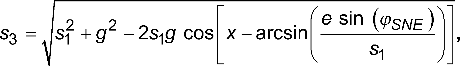
s3 = sqrt(s1^2+g^2-2*s1*g*cos(W9));
W4 = pi - HE;
W5 = acos((f^2-s2^2-g^2)/(-2*g*s2));
W6 = asin(a/c);
W7 = acos((d^2-c^2-s3^2)/(-2*c*s3));
W8 = acos((e^2-s2^2-s3^2)/(-2*s2*s3));
W11 = pi-W5-W6-W7-W8;
SKW = W5+W6+W7+W8-W4;
SKW_grad = (SKW * 180)/pi;
z(i,j) = SKW_grad;
end
end
% -------------------------Basis Datenmenge x, y, und z---------------------
% x = 0:0.025:1;
% y = 0:0.025:1;
%
% for i = 1 :length(x)
% for j = 1:length(y)
%
% z(i,j) = 100*sqrt(cos(y(j))+x(i))+100*sqrt(sin(x(i))+y(j))-acos(x(i)*y(j));
% end
% end
%
% -------------------------------------------------------------------------
%-------------------------Approximation 1ten Grades (in x-Richtung)--------
A = [2*sum(x.^2) 2*sum(x.^1) 2*sum(x.^0);
2*sum(x.^3) 2*sum(x.^2) 2*sum(x.^1);
2*sum(x.^4) 2*sum(x.^3) 2*sum(x.^2)];
Ainv = A^-1;
for i= 1:1 ength(z( 1,:))
%Ausgangsvektor w
w = z(:,i)';
b = [2*sum(w.*x.^0);
2*sum(w.*x.^1);
2*sum(w.*x.^2)];
% parameter solution vector p = A^-1 * z
p = Ainv * b;
for j=1:length(p)
p_1Grad(i,j) = p(j);
end
%This means q = a2*x^2 + a1*x...
q_1 = p(1)*x.^2 + p(2)*x.^1 + p(3)*x.^0;
R_1Grad(i) = (sum((w-q_1).^2)/sum(w))*100;
%plot(x,z(:, 5),x,q)
end
% -------------------------------------------------------------------------
%----------------Approximation 2ten Grades (in Parameter-Richtung)--------
A = [2*sum(y.^2) 2*sum(y.^1) 2*sum(y.^0);
2*sum(y.^3) 2*sum(y.^2) 2*sum(y.^1);
2*sum(y.^4) 2*sum(y.^3) 2*sum(y.^2)];
Ainv = A^-1;
figure;
for i = 1:length(p _1Grad(1,:))
%Eingangsvektor ist y, Ausgangsvektor ist solution(:,i)
w = p_1Grad(:,i)';
b = [2*sum(w.*y.^0);
2*sum(w.*y.^1);
2*sum(w.*y.^2)];
% parameter solution vector p = A^-1 * z
p = Ainv * b;
for j=1:length(p)
p_2Grad(i,j) = p(j);
end
%This means r = a2*y^2 + a1*y...
q_2= p(1)*x.^2 + p(2)*x.^1 + p(3)*x.^0;
R_2Grad(i) = (sum((w-q_2).^2)/sum(w))*100;
subplot(1,3,i); plot(y,p_1Grad(:,i)',y,q_2)
title(['Konvergenz 2.Grad ',num2str(i),'-ter Parametersatz'])
end
%------------------------------------------------------------------------------
%----------------Berechnung der Zielfunktion zum Abgleich --------
for i = 1:length(x)
for j = 1:length(y)
d1 = (p_2Grad(1,1)*y(j)^2 + p_2Grad(1,2)*y(j)^1 +
p_2Grad(1,3)*y(j)^0);
d2 = (p_2Grad(2, 1)*y(j)^2 + p_2Grad(2,2)*y(j)^1 +
p_2Grad(2,3)*y(j)^0);
d3 = (p_2Grad(3,1)*y(j)^2 + p_2Grad(3,2)*y(j)^1 +
p_2Grad(3,3)*y(j)^0);
q_3(i,j) = d1*x(i)^2 + d2*x(i)^1 + d3*x(i)^0;
end
end
%----------------Berechnung der Fehler ----------------------------------
R_ges = abs(q_3-z);
%Fehler der Approximation in Prozent
dR_ges = (R_ges ./ abs(z)).*100;
% Malen
figure;
h1 = surf(x,y,z);;
hold on
title(['Match des gesamten Feldes'])
h2 = surf(x,y,q_3);;
set(h2,'facealpha',0.4);
figure;
surf(x,y,dR_ges);
title(['Fehlerfeld in Prozent']) A source code for programming the method according to one embodiment is given below: clc
clear all
close all
%----------------------- Calculation of the map--------------------- ---
%map definition x = SNE angle° , y = HE angle°, z = map of
%seat angle°
SNEmin = 0;
SNE max = 40;
HE min = 0;
HE max = 50;
acc = 50;
x = SNEmin:((SNEmax-SNEmin)/acc):SNEmax;
y = HEmin:((HEmax-HEmin)/acc):HEmax;
%geometry definition
a = 43.00;
b = 271.62;
c = 275;
d = 100;
e = 35;
f= 306.4;
g = 90;
for i = 1 :length(x)
for j = 1:length(y)
SNE_grad = x(i);
HE_grad = y(j);
%angle in rad (radians)
SNE = (SNE_grad * pi)/180;
HE = (HE_grad * pi)/180;
s1 = sqrt(e^2+f^2-2*e*f*cos(SNE));
W3 = acos((e^2-f^2-s1^2)/(-2*fs1));
W9 = HE-W3;
s2 = sqrt(g^2+f^2-2*g*f*cos(HE));
s3 = sqrt(s1^2+g^2-2*s1*g*cos(W9));
W4 = pi - HE;
W5 = acos((f^2-s2^2-g^2)/(-2*g*s2));
W6 = asin(a/c);
W7 = acos((d^2-c^2-s3^2)/(-2*c*s3));
W8 = acos((e^2-s2^2-s3^2)/(-2*s2*s3));
W11 = pi-W5-W6-W7-W8;
SKW = W5+W6+W7+W8-W4;
SKW_grad = (SKW * 180)/pi;
z(i,j) = SKW_grad;
end
end
% -------------------------Base Dataset x, y, and z---------------- -----
%x = 0:0.025:1;
%y = 0:0.025:1;
%
% for i = 1 :length(x)
% for j = 1:length(y)
%
% z(i,j) = 100*sqrt(cos(y(j))+x(i))+100*sqrt(sin(x(i))+y(j))-acos(x(i) *y(j));
% final
% final
%
% ------------------------------------------------- ------------------------
%-------------------------Approximation of the 1st degree (in x-direction)--------
A = [2*sum(x.^2) 2*sum(x.^1) 2*sum(x.^0);
2*sum(x.^3) 2*sum(x.^2) 2*sum(x.^1);
2*sum(x.^4) 2*sum(x.^3) 2*sum(x.^2)];
Ainv = A^-1;
for i= 1:1 narrow(z( 1,:))
%Output Vector w
w = z(:,i)';
b = [2*sum(w.*x.^0);
2*sum(w.*x.^1);
2*sum(w.*x.^2)];
% parameter solution vector p = A^-1 * z
p = Ainv * b;
for j=1:length(p)
p_1degree(i,j) = p(j);
end
%This means q = a2*x^2 + a1*x...
q_1 = p(1)*x.^2 + p(2)*x.^1 + p(3)*x.^0;
R_1degree(i) = (sum((w-q_1).^2)/sum(w))*100;
%plot(x,z(:, 5),x,q)
end
% ------------------------------------------------- ------------------------
%----------------2nd degree approximation (in parameter direction)--------
A = [2*sum(y.^2) 2*sum(y.^1) 2*sum(y.^0);
2*sum(y.^3) 2*sum(y.^2) 2*sum(y.^1);
2*sum(y.^4) 2*sum(y.^3) 2*sum(y.^2)];
Ainv = A^-1;
figure;
for i = 1:length(p _1degree(1,:))
%input vector is y, output vector is solution(:,i)
w = p_1degree(:,i)';
b = [2*sum(w.*y.^0);
2*sum(w.*y.^1);
2*sum(w.*y.^2)];
% parameter solution vector p = A^-1 * z
p = Ainv * b;
for j=1:length(p)
p_2degrees(i,j) = p(j);
end
%This means r = a2*y^2 + a1*y...
q_2= p(1)*x.^2 + p(2)*x.^1 + p(3)*x.^0;
R_2degree(i) = (sum((w-q_2).^2)/sum(w))*100;
subplot(1,3,i); plot(y,p_1degree(:,i)',y,q_2)
title(['2nd degree convergence ',num2str(i),'-th parameter set'])
end
%------------------------------------------------ -----------------------------
%----------------Calculation of target function for matching--------
for i = 1:length(x)
for j = 1:length(y)
d1 = (p_2deg(1,1)*y(j)^2 + p_2deg(1,2)*y(j)^1 +
p_2degrees(1,3)*y(j)^0);
d2 = (p_2deg(2, 1)*y(j)^2 + p_2deg(2,2)*y(j)^1 +
p_2degrees(2,3)*y(j)^0);
d3 = (p_2deg(3,1)*y(j)^2 + p_2deg(3,2)*y(j)^1 +
p_2degrees(3,3)*y(j)^0);
q_3(i,j) = d1*x(i)^2 + d2*x(i)^1 + d3*x(i)^0;
end
end
%----------------Calculation of errors ------------------------------ ----
R_ges = abs(q_3-z);
%Error of the approximation in percent
dR_ges = (R_ges ./ abs(z)).*100;
% To paint
figure;
h1 = surf(x,y,z);;
hold on
title(['Match Entire Field'])
h2 = surf(x,y,q_3);;
set(h2,'facealpha',0.4);figure;surf(x,y,dR_ges);title(['Error Field Percentage'])
BezugszeichenlisteReference List
- 1, 1', 1"1, 1', 1"
- Schaltungcircuit
- 11, 11', 11"11, 11', 11"
- EingangEntry
- 12, 12', 12"12, 12', 12"
- Prozessorprocessor
- 1313
- SpeicherStorage
- 1414
- Ausgang der Schaltungoutput of the circuit
- 1515
- Ansteuereinheitcontrol unit
- 1616
- Ausgang des Prozessorsoutput of the processor
- D1, D2, D3D1, D2, D3
- Drehpunktepivot points
- W3, W4, W5, W6, W7, W8, W9W3, W4, W5, W6, W7, W8, W9
- Winkelangle
- a, b, c, d, e, f, ga, b, c, d, e, f, g
- Kantenlängenedge lengths
- φSNEφSNE
- Winkel SitzneigungseinstellerAngle seat recline adjuster
- φHEφHE
- Winkel HöheneinstellerAngle height adjuster
- φLNEφLNE
- Winkel LehnenneigungseinstellerAngle of backrest angle adjuster
- φSKφSK
- Winkel Sitzkissenangle seat cushion
Claims (16)


Priority Applications (1)
| Application Number | Priority Date | Filing Date | Title |
|---|---|---|---|
| DE102013102401.7A DE102013102401B4 (en) | 2013-03-11 | 2013-03-11 | vehicle seat adjustment |
Applications Claiming Priority (1)
| Application Number | Priority Date | Filing Date | Title |
|---|---|---|---|
| DE102013102401.7A DE102013102401B4 (en) | 2013-03-11 | 2013-03-11 | vehicle seat adjustment |
Publications (2)
| Publication Number | Publication Date |
|---|---|
| DE102013102401A1 DE102013102401A1 (en) | 2014-09-11 |
| DE102013102401B4 true DE102013102401B4 (en) | 2022-05-12 |
Family
ID=51385424
Family Applications (1)
| Application Number | Title | Priority Date | Filing Date |
|---|---|---|---|
| DE102013102401.7A Active DE102013102401B4 (en) | 2013-03-11 | 2013-03-11 | vehicle seat adjustment |
Country Status (1)
| Country | Link |
|---|---|
| DE (1) | DE102013102401B4 (en) |
Citations (6)
| Publication number | Priority date | Publication date | Assignee | Title |
|---|---|---|---|---|
| US4308584A (en) | 1978-12-20 | 1981-12-29 | Agency Of Industrial Science & Technology | Apparatus for control of manipulator |
| DE4228849C1 (en) | 1992-08-29 | 1993-10-14 | Daimler Benz Ag | Adjustable automobile seat with headrest - has setting motor controlling automatic adjustment of headrest in dependence on detected position adjustment of seat |
| DE69708524T2 (en) | 1996-06-28 | 2002-08-01 | Siemens Medical Systems, Inc. | Virtual compensator |
| US20070119647A1 (en) | 2004-11-09 | 2007-05-31 | Nissan Motor Co., Ltd. | Automatic driving position adjustment control system and method |
| DE102008053475A1 (en) | 2008-10-28 | 2010-04-29 | Dr. Ing. H.C. F. Porsche Aktiengesellschaft | Adjustable vehicle seat |
| DE102010038009A1 (en) | 2010-10-06 | 2012-04-12 | Dr. Ing. H.C. F. Porsche Aktiengesellschaft | Frame for seat in motor car, has backrest frame portion pivotable around pivot of frame, and pivot formed as seat separation point and comprising pivot bolt disassembled for separating seat back frame portion from cushion frame portion |
-
2013
- 2013-03-11 DE DE102013102401.7A patent/DE102013102401B4/en active Active
Patent Citations (6)
| Publication number | Priority date | Publication date | Assignee | Title |
|---|---|---|---|---|
| US4308584A (en) | 1978-12-20 | 1981-12-29 | Agency Of Industrial Science & Technology | Apparatus for control of manipulator |
| DE4228849C1 (en) | 1992-08-29 | 1993-10-14 | Daimler Benz Ag | Adjustable automobile seat with headrest - has setting motor controlling automatic adjustment of headrest in dependence on detected position adjustment of seat |
| DE69708524T2 (en) | 1996-06-28 | 2002-08-01 | Siemens Medical Systems, Inc. | Virtual compensator |
| US20070119647A1 (en) | 2004-11-09 | 2007-05-31 | Nissan Motor Co., Ltd. | Automatic driving position adjustment control system and method |
| DE102008053475A1 (en) | 2008-10-28 | 2010-04-29 | Dr. Ing. H.C. F. Porsche Aktiengesellschaft | Adjustable vehicle seat |
| DE102010038009A1 (en) | 2010-10-06 | 2012-04-12 | Dr. Ing. H.C. F. Porsche Aktiengesellschaft | Frame for seat in motor car, has backrest frame portion pivotable around pivot of frame, and pivot formed as seat separation point and comprising pivot bolt disassembled for separating seat back frame portion from cushion frame portion |
Also Published As
| Publication number | Publication date |
|---|---|
| DE102013102401A1 (en) | 2014-09-11 |
Similar Documents
| Publication | Publication Date | Title |
|---|---|---|
| DE102017105305B4 (en) | METHOD FOR AUTOMATIC DETERMINATION OF A SENSOR POSITION | |
| DE69515184T2 (en) | METHOD AND DEVICE FOR AUTOMATICALLY ADJUSTING MIRRORS | |
| DE102017124375A1 (en) | CONTROL PROCEDURES USING TRAILER RATING MEASUREMENTS FOR TRAILER REVERSE ASSISTANCE | |
| DE102009047476A1 (en) | Method and control unit for determining a section trajectory of a curve section of a roadway | |
| DE112016006989T5 (en) | VEHICLE ASSISTANCE AND VEHICLE ASSISTANCE PROCEDURE | |
| DE112016007206T5 (en) | Parking assist apparatus | |
| DE102015103279A1 (en) | Autonomous vehicle with reconfigurable interior | |
| DE112019001855B4 (en) | VEHICLE TAX DEVICE AND PROPERTY APPRAISAL METHOD | |
| DE102007047914A1 (en) | Seat device for vehicle, has drive control equipment that starts controlling of drive devices to move supporting sections in direction, if vehicle reaches point of kind of steering stored in mechanism for storing point of kind of steering | |
| DE102019214544A1 (en) | Method and device for determining a desired position of an environmental sensor of a vehicle | |
| DE102008060770A1 (en) | Driver aiding method for use during parking of car, involves producing representation of trajectory via stored reference circle data in dependent of steering angle, vehicle data, and position and adjustment of camera | |
| DE102016207435B4 (en) | Vehicle and system and method for generating feedback forces acting on a steering wheel of a steer-by-wire steering system | |
| DE102017119507B4 (en) | Method for the variable control of the sideslip angle of a vehicle with a rear wheel steering system | |
| DE102022124144A1 (en) | SYSTEMS AND METHODS TO ASSIST MANEUVERING OF A TRAILER TOWED BY A VEHICLE | |
| DE102017122169B4 (en) | Estimating a payload using electric power steering signals | |
| EP4264322A1 (en) | Method for calibrating at least one signal parameter and/or system parameter of a wave-based measurement system | |
| DE102015224080A1 (en) | Vehicle and map generating process for the vehicle | |
| DE102020209628A1 (en) | DRIVER ASSISTANCE DEVICE AND PROCEDURE FOR OPERATING THE SELEBN | |
| DE102013102401B4 (en) | vehicle seat adjustment | |
| DE102018221822B4 (en) | Torque compensation device and method for sudden steering action in a motor-driven power steering system | |
| DE102007013261B4 (en) | Method and device for estimating the lateral speed of a vehicle | |
| DE102017207393B4 (en) | METHOD AND SYSTEM FOR DETECTING A TILT ANGLE BY DETECTING A TORQUE CHANGE IN A VEHICLE | |
| DE102019204565A1 (en) | Method of maneuvering a vehicle | |
| DE69608381T2 (en) | Method and device for guiding a mobile object | |
| DE112020001530T5 (en) | SYSTEM AND METHOD FOR CONTROLLING THE SPEED AND COURSE OF A MOTOR VEHICLE BASED ON PREVIEW INFORMATION |
Legal Events
| Date | Code | Title | Description |
|---|---|---|---|
| R163 | Identified publications notified | ||
| R081 | Change of applicant/patentee |
Owner name: MINEBEA MITSUMI INC., JP Free format text: FORMER OWNER: MINEBEA CO., LTD., NAGANO, JP |
|
| R082 | Change of representative |
Representative=s name: BOEHMERT & BOEHMERT ANWALTSPARTNERSCHAFT MBB -, DE |
|
| R012 | Request for examination validly filed | ||
| R016 | Response to examination communication | ||
| R018 | Grant decision by examination section/examining division | ||
| R020 | Patent grant now final |