[go: up one dir, main page]

DE102013015108A1 - Positioning device for positioning an X-ray source - Google Patents

Positioning device for positioning an X-ray source Download PDF

Info

Publication number
DE102013015108A1
DE102013015108A1 DE102013015108.2A DE102013015108A DE102013015108A1 DE 102013015108 A1 DE102013015108 A1 DE 102013015108A1 DE 102013015108 A DE102013015108 A DE 102013015108A DE 102013015108 A1 DE102013015108 A1 DE 102013015108A1
Authority
DE
Germany
Prior art keywords
positioning device
ray source
contact surface
applicator
positioning
Prior art date
Legal status (The legal status is an assumption and is not a legal conclusion. Google has not performed a legal analysis and makes no representation as to the accuracy of the status listed.)
Withdrawn
Application number
DE102013015108.2A
Other languages
German (de)
Inventor
Frank Weigand
Current Assignee (The listed assignees may be inaccurate. Google has not performed a legal analysis and makes no representation or warranty as to the accuracy of the list.)
Carl Zeiss Meditec AG
Original Assignee
Carl Zeiss Meditec AG
Priority date (The priority date is an assumption and is not a legal conclusion. Google has not performed a legal analysis and makes no representation as to the accuracy of the date listed.)
Filing date
Publication date
Application filed by Carl Zeiss Meditec AG filed Critical Carl Zeiss Meditec AG
Priority to DE102013015108.2A priority Critical patent/DE102013015108A1/en
Publication of DE102013015108A1 publication Critical patent/DE102013015108A1/en
Withdrawn legal-status Critical Current

Links

Images

Classifications

    • AHUMAN NECESSITIES
    • A61MEDICAL OR VETERINARY SCIENCE; HYGIENE
    • A61NELECTROTHERAPY; MAGNETOTHERAPY; RADIATION THERAPY; ULTRASOUND THERAPY
    • A61N5/00Radiation therapy
    • A61N5/10X-ray therapy; Gamma-ray therapy; Particle-irradiation therapy
    • A61N5/1001X-ray therapy; Gamma-ray therapy; Particle-irradiation therapy using radiation sources introduced into or applied onto the body; brachytherapy
    • A61N5/1028X-ray therapy; Gamma-ray therapy; Particle-irradiation therapy using radiation sources introduced into or applied onto the body; brachytherapy using radiation sources applied onto the body
    • AHUMAN NECESSITIES
    • A61MEDICAL OR VETERINARY SCIENCE; HYGIENE
    • A61BDIAGNOSIS; SURGERY; IDENTIFICATION
    • A61B18/00Surgical instruments, devices or methods for transferring non-mechanical forms of energy to or from the body
    • A61B2018/00053Mechanical features of the instrument of device
    • A61B2018/00273Anchoring means for temporary attachment of a device to tissue
    • A61B2018/00291Anchoring means for temporary attachment of a device to tissue using suction
    • AHUMAN NECESSITIES
    • A61MEDICAL OR VETERINARY SCIENCE; HYGIENE
    • A61BDIAGNOSIS; SURGERY; IDENTIFICATION
    • A61B6/00Apparatus or devices for radiation diagnosis; Apparatus or devices for radiation diagnosis combined with radiation therapy equipment
    • A61B6/40Arrangements for generating radiation specially adapted for radiation diagnosis
    • AHUMAN NECESSITIES
    • A61MEDICAL OR VETERINARY SCIENCE; HYGIENE
    • A61NELECTROTHERAPY; MAGNETOTHERAPY; RADIATION THERAPY; ULTRASOUND THERAPY
    • A61N5/00Radiation therapy
    • A61N5/10X-ray therapy; Gamma-ray therapy; Particle-irradiation therapy
    • A61N5/1001X-ray therapy; Gamma-ray therapy; Particle-irradiation therapy using radiation sources introduced into or applied onto the body; brachytherapy
    • A61N2005/1019Sources therefor
    • A61N2005/1022Generators, e.g. X-ray tubes
    • AHUMAN NECESSITIES
    • A61MEDICAL OR VETERINARY SCIENCE; HYGIENE
    • A61NELECTROTHERAPY; MAGNETOTHERAPY; RADIATION THERAPY; ULTRASOUND THERAPY
    • A61N5/00Radiation therapy
    • A61N5/10X-ray therapy; Gamma-ray therapy; Particle-irradiation therapy
    • A61N2005/1085X-ray therapy; Gamma-ray therapy; Particle-irradiation therapy characterised by the type of particles applied to the patient
    • A61N2005/1091Kilovoltage or orthovoltage range photons

Landscapes

  • Health & Medical Sciences (AREA)
  • Engineering & Computer Science (AREA)
  • Biomedical Technology (AREA)
  • Pathology (AREA)
  • Nuclear Medicine, Radiotherapy & Molecular Imaging (AREA)
  • Radiology & Medical Imaging (AREA)
  • Life Sciences & Earth Sciences (AREA)
  • Animal Behavior & Ethology (AREA)
  • General Health & Medical Sciences (AREA)
  • Public Health (AREA)
  • Veterinary Medicine (AREA)
  • Radiation-Therapy Devices (AREA)

Abstract

Die Erfindung betrifft eine Positioniervorrichtung zur Positionierung einer Röntgenstrahlenquelle 601 relativ zu einer Gewebeoberfläche 202, mit einem formstabilen Grundkörper 101, 301, 701, 801, der eine Kontaktfläche 103, 303, 703, 803 aufweist, die mit der Gewebeoberfläche 202 in Kontakt gebracht werden kann.
Erfindungsgemäß umfasst die Positioniervorrichtung eine Kammer 104, 304, 704, 812 mit einer Öffnung 105, 311, 711, die derart in der Positioniervorrichtung angeordnet ist, dass sie durch Anlegen der Positioniervorrichtung an die Gewebeoberfläche verschlossen werden kann. Ferner sind Mittel zum Erzeugen eines Unterdrucks 108 vorhanden, mit deren Hilfe bei an der Gewebeoberfläche 202 angelegter Positioniervorrichtung ein Unterdruck in der Kammer 104, 312, 704, 812 erzeugbar ist, so dass die Gewebeoberfläche 202 an der Kontaktfläche 103, 303, 703, 803 anliegt.
The invention relates to a positioning device for positioning an X-ray source 601 relative to a tissue surface 202, with a dimensionally stable base 101, 301, 701, 801, which has a contact surface 103, 303, 703, 803, which can be brought into contact with the tissue surface 202 ,
According to the invention, the positioning device comprises a chamber 104, 304, 704, 812 with an opening 105, 311, 711, which is arranged in the positioning device such that it can be closed by applying the positioning device to the tissue surface. Furthermore, there are means for generating a negative pressure 108, with the aid of which a negative pressure can be generated in the chamber 104, 312, 704, 812 in the case of a positioning device applied to the tissue surface 202, so that the tissue surface 202 at the contact surface 103, 303, 703, 803 is applied.

Figure DE102013015108A1_0001

Description

Die Erfindung betrifft eine Positioniervorrichtung zur Positionierung einer Röntgenstrahlenquelle relativ zu einer Gewebeoberfläche. Die Positioniervorrichtung umfasst einen formstabilen Grundkörper, der eine Kontaktfläche aufweist, die mit der Gewebeoberfläche in Kontakt gebracht werden kann. Weiterhin betrifft die Erfindung einen Applikator für eine Röntgenstrahlenquelle mit einer solchen Positioniervorrichtung sowie eine Strahlentherapievorrichtung mit einer Röntgenstrahlenquelle und einer Positioniervorrichtung.The invention relates to a positioning device for positioning an X-ray source relative to a tissue surface. The positioning device comprises a dimensionally stable base body which has a contact surface which can be brought into contact with the tissue surface. Furthermore, the invention relates to an applicator for an X-ray source with such a positioning device and a radiotherapy device with an X-ray source and a positioning device.

Die Strahlentherapie stellt ein bewährtes Verfahren zur Bekämpfung von Krebstumoren oder von Tumorresten nach einer operativen Entfernung des Tumors dar. Dabei wird das betroffene Gewebe nach einem festgelegten Behandlungsplan der Strahlung einer Röntgenstrahlenquelle ausgesetzt, um die Tumorzellen zu zerstören. Die verwendeten Strahlentherapievorrichtungen lassen sich nach Art der verwendeten Röntgenstrahlenquellen unterscheiden. In einer Klasse von Strahlentherapievorrichtungen werden hochenergetische Röntgenstrahlenquellen zur Tumorbehandlung verwendet, deren Röntgenstrahlen von außerhalb auf den Körper des Patienten gerichtet werden. Nachteilig an diesen Strahlentherapievorrichtungen mit hochenergetischen Röntgenstrahlenquellen ist, dass die Strahlung dem Körper des Patienten immer aus einem Abstand zugeführt wird. Aufgrund von Streueffekten und von Ungenauigkeiten in der Strahlausrichtung lässt es sich praktisch nicht vermeiden, dass auch umliegendes, gesundes Gewebe einer Strahlendosis ausgesetzt ist.Radiation therapy is a proven method for combating cancerous tumors or tumor remnants after surgical removal of the tumor. The affected tissue is exposed to the radiation of an X-ray source according to a defined treatment plan in order to destroy the tumor cells. The radiotherapy devices used can be differentiated according to the type of X-ray sources used. One class of radiotherapy devices uses high energy X-ray sources for tumor treatment, whose X-rays are directed from the outside to the body of the patient. A disadvantage of these radiotherapy devices with high-energy X-ray sources is that the radiation is always supplied to the body of the patient from a distance. Due to scattering effects and inaccuracies in the beam alignment, it is practically unavoidable that even surrounding, healthy tissue is exposed to a radiation dose.

Um diesem Nachteil zu begegnen, werden in jüngster Zeit vermehrt miniaturisierte Strahlentherapievorrichtungen mit niedrigenergetischen Röntgenstrahlenquellen eingesetzt, bei denen die Röntgenstrahlung in unmittelbarer Nähe zum Behandlungsort erzeugt und abgegeben wird. Die Röntgenstrahlenquellen stehen dabei in der Regel unmittelbar oder über einen Applikator in Kontakt mit dem zu bestrahlenden Gewebe. Ein Vorteil derartiger Strahlentherapievorrichtungen besteht darin, dass das umliegende, gesunde Gewebes einer wesentlich geringeren Strahlenbelastung ausgesetzt ist.In order to counteract this disadvantage, recently miniaturized radiotherapy devices with low-energy x-ray sources are increasingly used in which the x-ray radiation is generated and delivered in the immediate vicinity of the treatment site. The x-ray sources are usually directly or via an applicator in contact with the tissue to be irradiated. An advantage of such radiation therapy devices is that the surrounding, healthy tissue is exposed to a much lower radiation exposure.

In der WO 2013/024086 A1 ist das Funktionsprinzip einer solchen miniaturisierten Strahlentherapievorrichtung zur Bestrahlung eines Gewebes mit niedrigenergetischer Röntgenstrahlung beschrieben. In einer Elektronenquelle werden zunächst Elektronen freigesetzt und in Richtung eines sogenannten Targets beschleunigt. Beim Auftreffen der Elektronen auf das Target, dass beispielsweise aus Gold besteht, werden die Elektronen stark verzögert, wodurch Röntgenstrahlung entsteht, die weitgehend ungerichtet abgegeben wird. Durch geeignete Abschirmungen lässt sich eine Abstrahlcharakteristik beeinflussen.In the WO 2013/024086 A1 is the principle of operation of such a miniaturized radiotherapy device for irradiation of a tissue with low-energy X-radiation described. In an electron source, electrons are initially released and accelerated in the direction of a so-called target. Upon impact of the electrons on the target, which consists for example of gold, the electrons are greatly delayed, resulting in X-rays, which is released largely non-directional. Suitable shielding can influence a radiation characteristic.

Eine Strahlentherapievorrichtung, die besonders zur Bestrahlung einer ebenen Gewebeoberfläche oder eines Gewebes unmittelbar unter einer ebenen Gewebeoberfläche geeignet ist, ist aus der DE 10 2009 058 581 A1 der Anmelderin bekannt. Die Strahlentherapievorrichtung umfasst ein sogenanntes Strahlungsquellenelement, das in einem Applikatorelement einer Applikatoreinrichtung aufgenommen ist. Das Applikatorelement weist ein freies Ende auf, das auf der zu bestrahlenden Oberfläche platziert werden kann. Die Applikatoreinrichtung kann mit einer als Befestigungseinrichtung bezeichneten Positioniervorrichtung auf der zu behandelnden Oberfläche positioniert werden. Hierfür wird die Positioniervorrichtung mit der Gewebeoberfläche verklebt oder an der Oberfläche festgenäht. Bei einer Verklebung besteht jedoch die Gefahr, dass diese sich während der Behandlung löst beziehungsweise erst gar nicht hält. Eine Vernähen erfordert Zeit und führt zu einer zusätzlichen Verletzung des Gewebes.A radiotherapy device which is particularly suitable for irradiation of a flat tissue surface or tissue immediately beneath a planar tissue surface is known from US 5,378,237 DE 10 2009 058 581 A1 the applicant known. The radiation therapy device comprises a so-called radiation source element, which is accommodated in an applicator element of an applicator device. The applicator element has a free end that can be placed on the surface to be irradiated. The applicator device can be positioned on the surface to be treated with a positioning device, referred to as a fastening device. For this purpose, the positioning device is glued to the fabric surface or sewn to the surface. In the case of bonding, however, there is a risk that it dissolves during treatment or does not even last. Sewing takes time and leads to additional tissue damage.

Eine Aufgabe der vorliegenden Erfindung besteht darin, eine Positioniervorrichtung für eine Röntgenstrahlenquelle bereitzustellen, die sich durch einen sicheren Halt auf der zu behandelnden Oberfläche auszeichnet und leicht wieder lösen lässt.An object of the present invention is to provide a positioning device for an X-ray source, which is characterized by a secure grip on the surface to be treated and easy to solve again.

Die Aufgabe wird durch eine Positioniervorrichtung mit den Merkmalen des Anspruchs 1 gelöst.The object is achieved by a positioning device with the features of claim 1.

Eine erfindungsgemäße Positioniervorrichtung umfasst eine Kammer mit einer Öffnung, wobei die Öffnung derart in der Positioniervorrichtung angeordnet ist, dass sie durch Anlegen der Positioniervorrichtung an die Gewebeoberfläche verschließbar ist. Ferner umfasst die Positioniervorrichtung Mittel zum Erzeugen eines Unterdrucks, mit deren Hilfe bei an der Gewebeoberfläche angelegter Positioniervorrichtung ein Unterdruck in der Kammer erzeugbar ist, durch den die Gewebeoberfläche an die Kontaktfläche anpressbar ist, so dass eine Normalkraft zwischen der Kontaktfläche und der Gewebeoberfläche verstärkt ist. Der Begriff „Unterdruck” ist dabei hier wie im Fortfolgenden so zu verstehen, dass ein durch die Mittel zur Erzeugung eines Unterdrucks in der Kammer der Positioniervorrichtung erzeugter Druck geringer ist als ein herrschender Umgebungsdruck.A positioning device according to the invention comprises a chamber with an opening, wherein the opening is arranged in the positioning device such that it can be closed by applying the positioning device to the tissue surface. Furthermore, the positioning device comprises means for generating a negative pressure, with the help of which applied to the tissue surface positioning a negative pressure in the chamber can be generated, through which the tissue surface is pressed against the contact surface, so that a normal force between the contact surface and the tissue surface is reinforced. The term "negative pressure" is understood here as in the following so that a pressure generated by the means for generating a negative pressure in the chamber of the positioning device is lower than a prevailing ambient pressure.

Nach einem sachgerechten Anlegen der Positioniervorrichtung an die Gewebeoberfläche ist die Öffnung der Kammer in der Positioniervorrichtung durch die Gewebeoberfläche verschlossen. Die Öffnung der Kammer kann sich in einem Abstand zu der Kontaktfläche befinden. Alternativ kann die Öffnung der Kammer auch in der Kontaktfläche ausgebildet sein. Durch die Erzeugung eines Unterdrucks in der Kammer wird die Gewebeoberfläche an die Kontaktfläche herangezogen, so dass eine kraftschlüssige Verbindung zwischen Kontaktfläche und Gewebeoberfläche entsteht, die nur unter Aufbietung vergleichsweise großer Kräfte überwunden werden kann. Dadurch ist die Gefahr eines Verrutschens der Positioniervorrichtung auf der Gewebeoberfläche deutlich verringert. Wird der Unterdruck beseitigt, lässt dich die Positioniervorrichtung leicht von der Gewebeoberfläche abheben.After a proper application of the positioning device to the tissue surface, the opening of the chamber in the positioning device is closed by the tissue surface. The opening of the chamber may be at a distance from the contact surface. Alternatively, the opening of the chamber may also be formed in the contact surface. By creating a negative pressure in the chamber, the tissue surface becomes used on the contact surface, so that a frictional connection between the contact surface and tissue surface is formed, which can be overcome only by putting comparatively large forces. As a result, the risk of slippage of the positioning device on the tissue surface is significantly reduced. If the negative pressure is eliminated, the positioning device will make you lift it off the tissue surface.

In einer Ausgestaltung der Erfindung ist die Kammer zumindest teilweise in dem Grundkörper ausgebildet, wobei die Öffnung der Kammer in der Ebene der Kontaktfläche angeordnet ist. Bevorzugt ist die Kammer als Leitung ausgestaltet, die mit den Mitteln zum Erzeugen eines Unterdrucks strömungsleitend verbunden ist und die an einem den Mitteln zum Erzeugen eines Unterdrucks gegenüberliegenden Ende in die Kontaktfläche ausmündet. Diese Ausgestaltungsform zeichnet sich durch besondere Einfachheit aus und ist kostengünstig herzustellen.In one embodiment of the invention, the chamber is at least partially formed in the base body, wherein the opening of the chamber is arranged in the plane of the contact surface. Preferably, the chamber is designed as a conduit which is flow-conductively connected to the means for generating a negative pressure and which opens at an opposite end of the means for generating a negative pressure in the contact surface. This embodiment is characterized by particular simplicity and is inexpensive to manufacture.

In einer Ausgestaltung der Erfindung ist auf dem Grundkörper eine erste Dichtvorrichtung ausgebildet, die die Kontaktfläche umschließt, wobei die Kammer durch die Kontaktfläche und die erste Dichtvorrichtung begrenzt ist und wobei die Öffnung der Kammer durch die erste Dichtvorrichtung beziehungsweise ein freies Ende der ersten Dichtvorrichtung festgelegt beziehungsweise gebildet ist. Dadurch ist eine besonders gute Abdichtung der (verschlossenen) Kammer gegenüber der Umgebung gewährleistet, so dass der Halt der Positioniervorrichtung auf der Gewebeoberfläche weiter verbessert ist.In one embodiment of the invention, a first sealing device is formed on the base body, which surrounds the contact surface, wherein the chamber is bounded by the contact surface and the first sealing device and wherein the opening of the chamber defined by the first sealing device or a free end of the first sealing device or is formed. As a result, a particularly good sealing of the (closed) chamber from the environment is ensured, so that the hold of the positioning device on the tissue surface is further improved.

In einer weiteren Ausgestaltung der Erfindung umfasst die Positioniervorrichtung eine Befestigungsvorrichtung zur Befestigung einer Röntgenstrahlenquelle oder eines Applikator der Röntgenstrahlenquelle an der Positioniervorrichtung, die derart ausgestaltet ist, dass bei befestigter Positioniervorrichtung eine Verschiebung der Röntgenstrahlenquelle in einer Ebene parallel zur Kontaktfläche zumindest weitgehend unterdrückt ist. Auf diese Weise kann die Röntgenstrahlenquelle relativ zu einem Punkt auf der Gewebeoberfläche fixiert werden, wobei eine Verschiebung unter einem Winkel zur Oberfläche zu dem Punkt hin oder von dem Punkt weg noch möglich ist.In a further embodiment of the invention, the positioning device comprises a fastening device for fixing an X-ray source or an applicator of the X-ray source to the positioning device, which is designed such that when the positioning device is fixed, a displacement of the X-ray source in a plane parallel to the contact surface is at least largely suppressed. In this way, the x-ray source can be fixed relative to a point on the tissue surface, with displacement at an angle to the surface toward or away from the point still possible.

In einer weiteren Ausgestaltung der Erfindung ist die Befestigungsvorrichtung derart ausgestaltet, dass bei befestigter Röntgenstrahlenquelle eine Verschiebung der Röntgenstrahlenquelle senkrecht zur Kontaktfläche zumindest weitgehend unterdrückt ist. Damit ist eine sichere Positionierung der Röntgenstrahlenquelle relativ zur Gewebeoberfläche in allen drei Raumrichtungen gewährleistet.In a further embodiment of the invention, the fastening device is designed such that when the X-ray source is fixed, a displacement of the X-ray source perpendicular to the contact surface is at least largely suppressed. This ensures a secure positioning of the X-ray source relative to the tissue surface in all three spatial directions.

In einer weiteren Ausgestaltung der Erfindung ist der Grundkörper der Positioniervorrichtung als Ring ausgestaltet, wobei die Kontaktfläche durch eine Oberseite des Rings gebildet ist und wobei der Ring eine Innenkontur aufweist, die an eine Außenkontur eines aufzunehmenden Bereichs der Röntgenstrahlenquelle oder eines Applikators der Röntgenstrahlenquelle angepasst ist. Dadurch ist eine sichere Abstützung und Fixierung des Röntgenstrahlenquelle oder des Applikators in der Positioniervorrichtung gewährleistet.In a further embodiment of the invention, the base body of the positioning device is designed as a ring, wherein the contact surface is formed by an upper side of the ring and wherein the ring has an inner contour which is adapted to an outer contour of a male portion of the X-ray source or an applicator of the X-ray source. This ensures a secure support and fixation of the X-ray source or the applicator in the positioning device.

In einer weiteren Ausgestaltung der Erfindung ist an einem Übergang von der Kontaktfläche zur Innenkontur eine zweite Dichtvorrichtung angeordnet, wobei die Öffnung der Kammer durch die erste Dichtvorrichtung beziehungsweise ein freies Ende der ersten Dichtvorrichtung und die zweite Dichtvorrichtung beziehungsweise ein freies Ende der zweiten Dichtvorrichtung festgelegt ist. Dadurch ist eine besonders gute Abdichtung der Kammer gegenüber der Umgebung gewährleistet, so dass der Halt der Positioniervorrichtung auf der Gewebeoberfläche weiter verbessert ist.In a further embodiment of the invention, a second sealing device is arranged at a transition from the contact surface to the inner contour, wherein the opening of the chamber by the first sealing device or a free end of the first sealing device and the second sealing device or a free end of the second sealing device is fixed. As a result, a particularly good sealing of the chamber from the environment is ensured, so that the hold of the positioning device on the fabric surface is further improved.

Ein erfindungsgemäßer Applikator für eine Röntgenstrahlenquelle ist mit einer Positioniervorrichtung nach einem der Ansprüche 1 bis 7 ausgestattet. Applikator und Positioniervorrichtung sind dabei als ein Bauteil ausgeführt oder fest miteinander verbunden. Die einteilige Ausgestaltung von Applikator und Positioniervorrichtung bietet gegenüber der aus dem Stand der Technik bekannten Lösung mit separatem Applikator und herkömmlicher Positioniervorrichtung den Vorteil, dass der Applikator sofort nach dem Aufsetzen der Positioniervorrichtung auf dem Gewebe mit der gesamten Kontaktfläche an dem Gewebe anliegt. Dadurch ist die Gefahr verringert, dass sich während der Positionierung des Applikators Fremdkörper oder Flüssigkeiten, zum Beispiel Wundflüssigkeit, auf der Gewebeoberfläche ansammeln, die sich nach dem Einfahren des Applikators in die Positioniervorrichtung zwischen der Kontaktfläche und der Gewebeoberfläche befinden. Ferner zeichnet sich diese Ausgestaltungsform dadurch aus, dass während der Positionierung des Applikators auf der Gewebeoberfläche keine Luft zwischen der Kontaktfläche und der Gewebeoberfläche eingeschlossen werden kann, was zu einer Fehlpositionierung der Röntgenquelle fahren würde.An applicator according to the invention for an X-ray source is equipped with a positioning device according to one of claims 1 to 7. Applicator and positioning device are designed as a component or firmly connected. The one-piece design of the applicator and positioning device offers over the known from the prior art solution with a separate applicator and conventional positioning device the advantage that the applicator rests immediately after placing the positioning on the fabric with the entire contact surface of the tissue. This reduces the risk that, during the positioning of the applicator, foreign bodies or liquids, for example wound fluid, accumulate on the tissue surface, which after insertion of the applicator are located in the positioning device between the contact surface and the tissue surface. Furthermore, this embodiment is characterized in that during the positioning of the applicator on the tissue surface, no air between the contact surface and the tissue surface can be trapped, which would lead to a mispositioning of the X-ray source.

Eine erfindungsgemäße Strahlentherapievorrichtung umfasst eine Positioniervorrichtung zur Positionierung der Röntgenstrahlenquelle relativ zu einer Gewebeoberfläche.A radiotherapy device according to the invention comprises a positioning device for positioning the X-ray source relative to a tissue surface.

Im Nachfolgenden wird die Erfindung anhand der Zeichnungen näher erläutert.In the following the invention will be explained in more detail with reference to the drawings.

Dabei zeigen im EinzelnenThis shows in detail
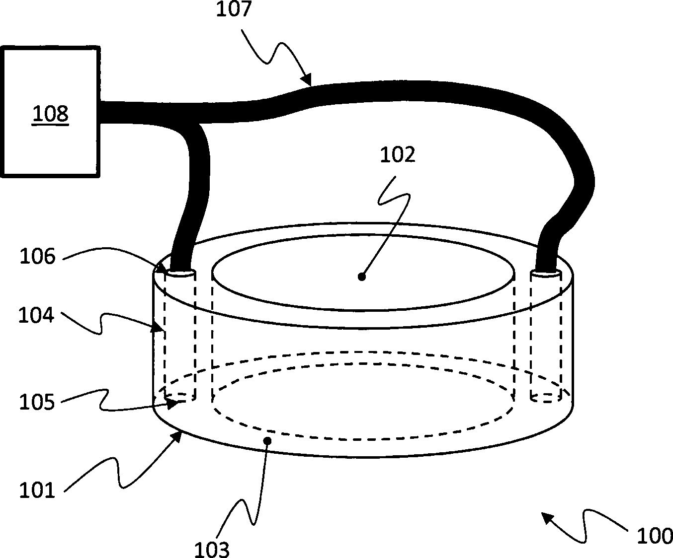
1: eine erste Ausführungsform einer erfindungsgemäßen Positionierhilfe; 1 a first embodiment of a positioning aid according to the invention;

2: die Positioniervorrichtung aus 1 in einer Schnittdarstellung; 2 : the positioning device off 1 in a sectional view;

3: eine zweite Ausführungsform einer erfindungsgemäßen Positionierhilfe; 3 a second embodiment of a positioning aid according to the invention;

4: die Positioniervorrichtung aus 3 in einer aufgesetzten Position; 4 : the positioning device off 3 in an attached position;

5: die Positioniervorrichtung aus 3 in einer fixierten Position; 5 : the positioning device off 3 in a fixed position;

6: die Positioniervorrichtung aus 1 oder 3 im Zusammenspiel mit einer Strahlentherapievorrichtung; 6 : the positioning device off 1 or 3 in interaction with a radiotherapy device;

7: eine erste Ausführungsform eines erfindungsgemäßen Applikators mit Positioniervorrichtung; 7 a first embodiment of an applicator according to the invention with positioning device;

8: eine zweite Ausführungsform eines erfindungsgemäßen Applikators mit Positioniervorrichtung; und 8th a second embodiment of an applicator according to the invention with positioning device; and

9: den Applikator aus 8 in einer fixierten Position. 9 : the applicator off 8th in a fixed position.

In 1 ist ein erstes Ausführungsbeispiel einer erfindungsgemäßen Positioniervorrichtung 100 zur Positionierung einer Röntgenstrahlenquelle relativ zu einer Gewebeoberfläche dargestellt. Die Positioniervorrichtung umfasst einen Grundkörper, der als Ring 101 ausgebildet ist und eine beispielsweise zylindrische, den Grundkörper durchdringende Aufnahmeöffnung 102 umfasst. Die Aufnahmeöffnung 102 weist eine Innenkontur auf, die an eine Außenkontur einer aufzunehmenden Röntgenstrahlenquelle oder eines aufzunehmenden Applikators einer Röntgenstrahlenquelle angepasst ist. Auf einer Seite des Rings 101 ist eine ebene Kontaktfläche 103 ausgebildet, die mit der Gewebeoberfläche in Kontakt gebracht werden kann, beziehungsweise indem der Ring 101 auf die Gewebeoberfläche aufgelegt wird. Ohne Einschränkung der Allgemeinheit kann die Kontaktfläche 103 auch eine von einer ebenen Form abweichende, definierte Formgebung aufweisen. Beispielsweise kann die Kontaktfläche auch konvex oder konkav und sphärisch oder asphärisch ausgeführt sein.In 1 is a first embodiment of a positioning device according to the invention 100 for positioning an x-ray source relative to a tissue surface. The positioning device comprises a base body, which serves as a ring 101 is formed and an example cylindrical, the main body penetrating receiving opening 102 includes. The receiving opening 102 has an inner contour, which is adapted to an outer contour of a male X-ray source or a male applicator of an X-ray source. On one side of the ring 101 is a flat contact surface 103 formed, which can be brought into contact with the tissue surface, or by the ring 101 is placed on the tissue surface. Without restriction of generality, the contact surface 103 also have a defined shape deviating from a planar shape. For example, the contact surface may also be convex or concave and spherical or aspherical.

In dem Ring 101 sind zwei Kammern 104 ausgebildet, die an einer Seite in Öffnungen 105 in der Kontaktfläche 103 ausmünden. An der der Kontaktfläche gegenüberliegenden Seite des Rings 101 sind die Kammern mit Leitungsanschlüssen 106 verbunden. Die Kammern können auf vielfältige Weisen hergestellt werden. In dem vorliegenden Ausführungsbeispiel sind die Kammern als Bohrungen 104 ausgeführt. Ohne Einschränkung der Allgemeinheit können auch mehr als zwei Kammern beziehungsweise Bohrungen vorgesehen sein, die jeweils an einer Seite in die Kontaktfläche und an der anderen Seite in Leitungsanschlüsse ausmünden. In einem weiteren, nicht dargestellten Ausführungsbeispiel können die Öffnungen 105 der Bohrungen 104 in der Kontaktfläche 103 zumindest teilweise auch über einen beispielsweise ringförmigen Kanal in der Kontaktfläche miteinander verbunden sein.In the ring 101 are two chambers 104 formed on one side in openings 105 in the contact area 103 open out. At the opposite side of the contact surface of the ring 101 are the chambers with pipe connections 106 connected. The chambers can be made in a variety of ways. In the present embodiment, the chambers are as bores 104 executed. Without limiting the generality, more than two chambers or bores can also be provided, each of which opens into the contact area on one side and into line connections on the other side. In a further, not shown embodiment, the openings 105 drilling 104 in the contact area 103 be at least partially connected via an example annular channel in the contact surface with each other.

Die Bohrungen 104 sind über die Leitungsanschlüsse 106 und über Schlauchleitungen 107 mit Mitteln zum Erzeugen eines Unterdrucks verbunden, die in diesem Ausführungsbeispiel als Vakuumpumpe 108 ausgeführt sind.The holes 104 are over the line connections 106 and over hose lines 107 connected to means for generating a negative pressure, in this embodiment as a vacuum pump 108 are executed.

Das Funktionsprinzip einer Fixierung der Positioniervorrichtung auf einer Gewebeoberfläche 202 ist in 2 dargestellt. Ein zu bestrahlendes Gewebe 201 befindet sich auf beziehungsweise unmittelbar unter einer Gewebeoberfläche 202a. Der Ring 101 wird so auf der Gewebeoberfläche 202 positioniert, dass er sich um das zu bestrahlende Gewebe 201 herum erstreckt, wobei die Öffnungen 105 der Bohrungen 104 durch die Gewebeoberfläche 202b verschlossen sind. Bei korrekter Positionierung des Rings 101 befindet sich das zu bestrahlende Gewebe 201 im Bereich der Aufnahmeöffnung 102 des Rings 101. Mit Hilfe der (in 2 nicht dargestellten) Vakuumpumpe 108 wird nachfolgend ein Unterdruck erzeugt, durch den der Ring 101 an die das zu bestrahlende Gewebe 201 umgebende Gewebeoberfläche 202b angesaugt wird. Dadurch entsteht eine Normalkraft zwischen der Kontaktfläche 103 des Rings 101 und der mit der Kontaktfläche 103 in Berührung stehenden Gewebeoberfläche 202b, so dass eine Haftung des Rings 101 auf der Gewebeoberfläche 202 verbessert ist. Durch die definierte, in diesem Ausführungsbeispiel ebene Form der Kontaktfläche 103 wird die Gewebeoberfläche 202b unter dem Ring in eine an die Form der Kontaktfläche 103 angepasste Lage gebracht.The functional principle of a fixation of the positioning device on a tissue surface 202 is in 2 shown. A tissue to be irradiated 201 is located on or immediately below a tissue surface 202a , The ring 101 becomes so on the tissue surface 202 positioned it around the tissue to be irradiated 201 extends around, with the openings 105 drilling 104 through the tissue surface 202b are closed. With correct positioning of the ring 101 is the tissue to be irradiated 201 in the area of the receiving opening 102 of the ring 101 , With the help of (in 2 not shown) vacuum pump 108 Subsequently, a negative pressure is generated, through which the ring 101 to the tissue to be irradiated 201 surrounding tissue surface 202b is sucked. This creates a normal force between the contact surface 103 of the ring 101 and the one with the contact surface 103 in contact with the tissue surface 202b , so that adhesion of the ring 101 on the tissue surface 202 is improved. By the defined, in this embodiment, planar shape of the contact surface 103 becomes the tissue surface 202b under the ring in one to the shape of the contact surface 103 adjusted position.

Damit weist auch die Gewebeoberfläche 202a im Bereich der Aufnahmeöffnung 102 des Rings 101 oberhalb des zu bestrahlenden Gewebes 201 eine definierte, durch die Kontaktfläche 103 des Rings 101 bestimmte Form auf. Wie nachfolgend noch genauer erläutert wird, lässt sich anschließend die Röntgenstrahlenquelle oder ein Applikator einer Röntgenstrahlenquelle nach Einbringen derselben in die Aufnahmeöffnung 102 des Rings 101 relativ zu der Gewebeoberfläche 202 ausrichten.This also indicates the tissue surface 202a in the area of the receiving opening 102 of the ring 101 above the tissue to be irradiated 201 a defined, through the contact surface 103 of the ring 101 certain form. As will be explained in more detail below, then the X-ray source or an applicator of an X-ray source after insertion of the same can be in the receiving opening 102 of the ring 101 relative to the tissue surface 202 align.

In den 3 bis 5 ist eine zweite Ausführungsform einer erfindungsgemäßen Positioniervorrichtung dargestellt, die als Ring 301 mit einer Aufnahmeöffnung 302 und einer Kontaktfläche 303 ausgestaltet ist. In dem Ring 301 sind Bohrungen 304 eingebracht, die über Leitungsanschlüsse 306 und Schlauchleitungen 307 mit einer in den Figuren nicht dargestellten Vakuumpumpe in Verbindung stehen. Von der in den 1 und 2 dargestellten Ausführungsform unterscheidet sich die zweite Ausführungsform der Erfindung dadurch, dass entlang eines Außenrands der Kontaktfläche 303 eine erste Dichtvorrichtung in Form einer ersten Gummilippe 309 angeordnet ist. An dem Übergang von der Kontaktfläche 303 zur Innenkontur der Aufnahmeöffnung 302 ist eine zweite Dichtvorrichtung angebracht, die in diesem Ausführungsbeispiel als zweite Gummilippe 310 ausgeführt ist. In anderen, nicht dargestellten Ausführungsbeispielen können die erste Dichtvorrichtung und/oder die zweite Dichtvorrichtung auch als Faltenbalg oder allgemein als beliebiges anderes Mittel zur luftdichten Abdichtung des Raums zwischen der Kontaktfläche und der Gewebeoberfläche gegenüber der Umgebung ausgestaltet sein.In the 3 to 5 is a second embodiment of a positioning device according to the invention shown as a ring 301 with a receiving opening 302 and a contact surface 303 is designed. In the ring 301 are holes 304 introduced, via line connections 306 and hose lines 307 with a not shown in the figures vacuum pump in connection. From the in the 1 and 2 illustrated embodiment, the second embodiment of the invention differs in that along an outer edge of the contact surface 303 a first sealing device in the form of a first rubber lip 309 is arranged. At the transition from the contact surface 303 to the inner contour of the receiving opening 302 a second sealing device is mounted, which in this embodiment as a second rubber lip 310 is executed. In other embodiments, not shown, the first sealing device and / or the second sealing device may also be designed as bellows or in general as any other means for airtight sealing of the space between the contact surface and the tissue surface relative to the environment.

Durch die Kontaktfläche 303, die erste Gummilippe 309 und die zweite Gummilippe 310 ist eine Kammer 312 gebildet, die an einer der Kontaktfläche 303 gegenüberliegenden Seite eine Öffnung 311 aufweist, die durch die freien Enden der ersten Gummilippe 309 und der zweiten Gummilippe 310 begrenzt ist. Aus 4 ist ersichtlich, dass die Öffnung 311 nach dem Positionieren des Rings 301 auf der Gewebeoberfläche 202 um das zu bestrahlende Gewebe herum durch die Gewebeoberfläche 202b verschlossen ist. Dadurch ist ein Volumen gebildet, das durch die Kontaktfläche 303, die erste Gummilippe 309, die zweite Gummilippe 310 sowie die Gewebeoberfläche 202b begrenzt und über die Bohrungen 304 sowie die Schlauchleitungen 307 mit der Vakuumpumpe verbunden ist. Mit Hilfe der Vakuumpumpe wird die Luft aus dem Volumen abgesaugt, so dass die Kontaktfläche 303 des Rings 301 an die Gewebeoberfläche 202b gepresst wird (5). Dadurch wird der Ring 301 wie im ersten Ausführungsbeispiel an die Gewebeoberfläche 202b herangesogen, und es entsteht eine Normalkraft zwischen der Kontaktfläche 303 des Rings 301 und der mit der Kontaktfläche 303 in Berührung stehenden Gewebeoberfläche 202b, durch die die Haftung des Rings 301 auf der Gewebeoberfläche 202 verbessert ist. Durch die definierte Form der Kontaktfläche 303 wird die Gewebeoberfläche 202b unter dem Ring in eine an die Form der Kontaktfläche 303 angepasste Lage gebracht, so dass eine Röntgenstrahlenquelle oder ein Applikator einer Röntgenstrahlenquelle nach Einbringen in die Aufnahmeöffnung 302 relativ zu der Gewebeoberfläche 202 ausgerichtet werden kann. Ein Vorteil der zweiten Ausführungsform besteht darin, dass durch die Abdichtung der Kontaktfläche 303 mit geeigneten Dichtvorrichtungen eine größere Normalkraft zwischen der Kontaktfläche und der Gewebeoberfläche erzeugt werden kann, wodurch die Haftung der Positioniervorrichtung auf der Gewebeoberfläche verbessert ist. Außerdem kann durch die Vakuumpumpe auch eventuell während des Positioniervorgangs eingetretene Wundflüssigkeit aus der Kammer 312 entfernt werden.Through the contact surface 303 , the first rubber lip 309 and the second rubber lip 310 is a chamber 312 formed at one of the contact surface 303 opposite side an opening 311 passing through the free ends of the first rubber lip 309 and the second rubber lip 310 is limited. Out 4 it can be seen that the opening 311 after positioning the ring 301 on the tissue surface 202 around the tissue to be irradiated through the tissue surface 202b is closed. As a result, a volume is formed by the contact surface 303 , the first rubber lip 309 , the second rubber lip 310 as well as the tissue surface 202b limited and over the holes 304 as well as the hose lines 307 connected to the vacuum pump. With the help of the vacuum pump, the air is sucked out of the volume, so that the contact surface 303 of the ring 301 to the tissue surface 202b is pressed ( 5 ). This will make the ring 301 as in the first embodiment of the tissue surface 202b pulled in, and there is a normal force between the contact surface 303 of the ring 301 and the one with the contact surface 303 in contact with the tissue surface 202b through which the adhesion of the ring 301 on the tissue surface 202 is improved. Due to the defined shape of the contact surface 303 becomes the tissue surface 202b under the ring in one to the shape of the contact surface 303 adapted position, so that an X-ray source or an applicator of an X-ray source after insertion into the receiving opening 302 relative to the tissue surface 202 can be aligned. An advantage of the second embodiment is that the sealing of the contact surface 303 With suitable sealing devices, a larger normal force can be generated between the contact surface and the tissue surface, whereby the adhesion of the positioning device is improved on the tissue surface. In addition, by the vacuum pump also possibly occurring during the positioning wound fluid from the chamber 312 be removed.

In 6 ist die Positioniervorrichtung im Zusammenspiel mit einer miniaturisierten Strahlentherapievorrichtung 600 dargestellt. Die Strahlentherapievorrichtung 600 umfasst eine niederenergetische Röntgenstrahlenquelle 601 zur Erzeugung weicher Röntgenstrahlung sowie einen Applikator 620.In 6 is the positioning device in interaction with a miniaturized radiotherapy device 600 shown. The radiotherapy device 600 includes a low energy X-ray source 601 for generating soft X-radiation as well as an applicator 620 ,

Die Röntgenstrahlenquelle 601 weist eine Elektronenquelle 603 zur Erzeugung eines Elektronenstrahl 604 auf. Mittels elektromagnetischer Ablenkelemente 605, zum Beispiel Spulen, lässt sich die Bahn des Elektronenstrahls beeinflussen. Die Röntgenstrahlenquelle umfasst ferner ein Sondenelement 606 mit einem freien Ende 607, in dem ein sogenanntes Target 608 angeordnet ist, das beispielsweise aus Gold besteht. Beim Aufprall des Elektronenstrahls 604 auf das Target 608 werden die Elektronen stark verzögert, wodurch Röntgenstrahlung freigesetzt wird, die weitgehend ungerichtet abgegeben wird. Der Aufprallort des Elektronenstrahls auf dem Target lässt sich mit Hilfe der elektromagnetischen Ablenkelemente 605 einstellen, wodurch die Abstrahlcharakteristik der Röntgenstrahlenquelle beeinflusst werden kann. Die erzeugte Röntgenstrahlung weist eine Strahlungsenergie von 0 bis maximal 100 keV, insbesondere von 0 bis 50 keV auf.The X-ray source 601 has an electron source 603 for generating an electron beam 604 on. By means of electromagnetic deflection elements 605 , For example, coils, the path of the electron beam can be influenced. The x-ray source further comprises a probe element 606 with a free end 607 in which a so-called target 608 is arranged, which consists for example of gold. Upon impact of the electron beam 604 on the target 608 The electrons are greatly delayed, whereby X-ray radiation is released, which is largely discharged undirected. The impact location of the electron beam on the target can be determined by means of the electromagnetic deflection elements 605 adjust, whereby the radiation characteristic of the X-ray source can be influenced. The generated X-ray radiation has a radiation energy of 0 to a maximum of 100 keV, in particular from 0 to 50 keV.

Die Röntgenstrahlenquelle 601 beinhaltet ferner einen Fußbereich 609, an dem ein Applikator 620 der Strahlentherapievorrichtung 600 befestigbar ist.The X-ray source 601 also includes a foot area 609 on which an applicator 620 the radiotherapy device 600 is fastened.

Ein freies Ende 621 des Applikators 620 weist in radialer Richtung eine unterschiedliche Massenverteilung auf, so dass die durch den Aufprall des Elektronenstrahls 604 auf dem Target 608 erzeugte Röntgenstrahlung in Abhängigkeit von der Abstrahlrichtung unterschiedlich stark abgeschwächt wird. Dadurch lässt sich die Abstrahlcharakteristik der Röntgenstrahlung aus dem Applikator 620 heraus beeinflussen. Durch eine geeignete Wahl der Massenverteilung ist eine zumindest annähernd konstante Strahlungsintensität in einer Austrittsebene 622 des Applikators 620 einstellbar.A free end 621 of the applicator 620 has a different mass distribution in the radial direction, so that by the impact of the electron beam 604 on the target 608 generated X-ray radiation is attenuated to different extents depending on the emission direction. This allows the emission characteristic of the X-ray radiation from the applicator 620 influence out. By a suitable choice of the mass distribution is an at least approximately constant radiation intensity in an exit plane 622 of the applicator 620 adjustable.

Der Applikator 620 ist zylinderförmig ausgeführt, wobei eine Außenkontur des Zylinders in Größe und Form an die Innenkontur der Aufnahmeöffnung 102 der Positioniervorrichtung 100 angepasst ist. Nachdem die Positioniervorrichtung wie vorstehend beschrieben auf der Gewebeoberfläche fixiert ist, kann der Applikator 620 in die Aufnahmeöffnung 102 der Positioniervorrichtung 100 eingeführt und entlang der Längsachse des Applikators beziehungsweise der Längsachse der Positioniervorrichtung auf dem zu bestrahlenden Gewebe 201 positioniert werden. Dabei kann wahlweise erst der Applikator 620 in die Aufnahmeöffnung 102 und anschließend die Röntgenstrahlenquelle 601 in den Applikator 620 eingeführt werden, oder der Applikator 620 wird zuerst an der Röntgenstrahlenquelle 601 befestigt und beide gemeinsam werden anschließend in die Positioniervorrichtung eingeführt.The applicator 620 is cylindrical, wherein an outer contour of the cylinder in size and shape to the inner contour of the receiving opening 102 the positioning device 100 is adjusted. After the positioning device is fixed on the tissue surface as described above, the applicator can 620 in the receiving opening 102 the positioning device 100 introduced and along the longitudinal axis of the applicator or the longitudinal axis of the positioning device on the tissue to be irradiated 201 positioned become. Optionally, the applicator can be used first 620 in the receiving opening 102 and then the X-ray source 601 in the applicator 620 be introduced, or the applicator 620 is first at the X-ray source 601 attached and both together are then inserted into the positioning device.

Die Positioniervorrichtung ist mit Hilfe der Vakuumpumpe sicher auf der Gewebeoberfläche fixiert. Durch die an die Innenkontur der Aufnahmeöffnung angepasste Außenkontur des Applikators ist ein Verrutschen oder Verschieben des Applikators parallel zur Gewebeoberfläche beziehungsweise zur Kontaktfläche der Positioniervorrichtung weitgehend verhindert. Der Applikator lässt sich sicher auf der zu bestrahlenden Oberfläche positionieren, so dass die Röntgenstrahlungsquelle (und hierbei insbesondere das Target 608, in dem die Röntgenstrahlung entsteht,) auf definierte Art und Weise relativ zu der zu bestrahlenden Gewebeoberfläche ausgerichtet ist.The positioning device is securely fixed on the tissue surface with the help of the vacuum pump. By adapted to the inner contour of the receiving opening outer contour of the applicator slipping or displacement of the applicator is largely prevented parallel to the tissue surface or the contact surface of the positioning device. The applicator can be safely positioned on the surface to be irradiated, so that the X-ray source (and in particular the target 608 , in which the X-radiation is formed,) is oriented in a defined manner relative to the tissue surface to be irradiated.

In einer nicht dargestellten Ausführungsform der Erfindung umfasst die Positioniervorrichtung eine Befestigungsvorrichtung zur Befestigung des Applikators oder der Röntgenstrahlenquelle an der Positioniervorrichtung, durch die nach dem Einführen des Applikators oder der Röntgenstrahlenquelle in die Positioniervorrichtung auch ein Verschieben des Applikators oder der Röntgenstrahlenquelle in einer Richtung senkrecht zu der Kontaktfläche zumindest weitgehend unterdrückt ist. Damit ist der Applikator in allen drei Raumrichtungen in der Positioniervorrichtung fixiert, so dass auch der Abstand zwischen dem Target und der Gewebeoberfläche sicher und wohldefiniert eingestellt ist.In an embodiment of the invention which is not shown, the positioning device comprises a fastening device for fastening the applicator or the X-ray source to the positioning device, by means of which the applicator or the X-ray source is also displaced in a direction perpendicular to the position after the applicator or X-ray source has been inserted into the positioning device Contact surface is at least largely suppressed. Thus, the applicator is fixed in all three spatial directions in the positioning device, so that the distance between the target and the tissue surface is set safe and well-defined.

In 7 ist eine erste Ausführungsform eines erfindungsgemäßen Applikators 720 mit einer Positioniervorrichtung 701 dargestellt. Der wesentliche Unterschied zu der in 6 dargestellten Ausführungsform der Erfindung besteht darin, dass die Positioniervorrichtung 701 und der Applikator 720 einstückig ausgeführt sind. Zur Bestrahlung wird der Applikator 720 mit der Positioniervorrichtung 701 auf das zu bestrahlende Gewebe 201 aufgesetzt. In der Positioniervorrichtungen sind Kammern in Form von Bohrungen 704 vorhanden, die an einer Seite in Öffnungen 705 in einer Kontaktfläche 703 des Applikators 720 ausmünden. Mit Hilfe der in 7 nicht dargestellten Vakuumpumpe ist ein Unterdruck in den Bohrungen 704 erzeugbar, durch den der Applikator an die Gewebeoberfläche 202 herangesogen wird, so dass der Gewebeoberfläche die Form der Kontaktfläche aufgeprägt wird. Diese Ausgestaltungsform zeichnet sich dadurch aus, dass weniger Arbeitsgänge zur Positionierung der Röntgenstrahlenquelle und speziell des Targets 708 relativ zur Gewebeoberfläche 202 erforderlich sind, und dass eine Ansammlung von Gewebeflüssigkeit oder Luft unter dem Applikator 720 während des Positionierungsvorgangs weitgehend vermieden wird.In 7 is a first embodiment of an applicator according to the invention 720 with a positioning device 701 shown. The main difference to the in 6 illustrated embodiment of the invention is that the positioning device 701 and the applicator 720 are made in one piece. For irradiation, the applicator 720 with the positioning device 701 on the tissue to be irradiated 201 placed. In the positioning devices are chambers in the form of holes 704 present, on one side in openings 705 in a contact area 703 of the applicator 720 open out. With the help of in 7 Vacuum pump, not shown, is a negative pressure in the holes 704 producible, by which the applicator to the tissue surface 202 is sucked, so that the tissue surface is impressed on the shape of the contact surface. This embodiment is characterized in that fewer operations for positioning the X-ray source and especially of the target 708 relative to the tissue surface 202 are required, and that an accumulation of tissue fluid or air under the applicator 720 is largely avoided during the positioning process.

In 8 ist eine weitere Ausführungsform eines erfindungsgemäßen Applikators 820 mit Positioniervorrichtung 801 dargestellt. Der Applikator unterscheidet sich von dem zuvor behandelten Ausführungsbeispiel dadurch, dass eine erste Dichtvorrichtung in Form einer Gummilippe 809 vorhanden ist, die die Kontaktfläche 803 des Applikators 820 umschließt. Durch die Kontaktfläche 803 und die umlaufende Gummilippe 809 ist eine Kammer 812 gebildet, die an einer der Kontaktfläche 803 gegenüberliegenden Seite eine Öffnung aufweist, die durch das freie Ende der Gummilippe 809 begrenzt ist. Aus 8 ist ersichtlich, dass die Öffnung nach dem Positionieren des Applikators 820 auf der Gewebeoberfläche 202 durch die Gewebeoberfläche verschlossen ist. Dadurch ist ein Volumen gebildet, das durch die Kontaktfläche 803, die Gummilippe 809 und die Gewebeoberfläche 202 begrenzt und über die Bohrungen 804 sowie die Schlauchleitungen 807 mit der (nicht dargestellten) Vakuumpumpe verbunden ist. Mit Hilfe der Vakuumpumpe wird die Luft aus diesem Volumen abgesaugt, so dass die Kontaktfläche 803 des Applikators 820 an die Gewebeoberfläche 202 gepresst wird (9). Dadurch wird der Applikator an die Gewebeoberfläche 202 herangesogen, und es entsteht eine Normalkraft zwischen der Kontaktfläche 803 und der mit der Kontaktfläche in Berührung stehenden Gewebeoberfläche 202, durch die die Haftung des Applikators auf der Gewebeoberfläche 202 verbessert ist. Durch die definierte Form der Kontaktfläche 803 wird der Gewebeoberfläche 202 unter dem Applikator die Form der Kontaktfläche 803 aufgeprägt, so dass die Röntgenstrahlenquelle relativ zu der Gewebeoberfläche 202 ausgerichtet ist. Ein Vorteil dieser Ausführungsform im Vergleich zu der vorhergehend beschriebenen Ausführungsform besteht darin, dass durch die Abdichtung der Kontaktfläche 803 mit einer geeigneten Dichtvorrichtung eine größere Normalkraft zwischen der Kontaktfläche und der Gewebeoberfläche erzeugt werden kann, wodurch die Haftung des Applikators auf der Gewebeoberfläche weiter verbessert ist. Außerdem kann durch die Vakuumpumpe auch eventuell während des Positioniervorgangs eingetretene Wundflüssigkeit aus der Kammer 812 entfernt werden. Dadurch ist die Gefahr einer Fehlbestrahlung verringert, die durch Wundflüssigkeit zwischen dem Applikator und dem zu bestrahlenden Gewebe verursacht werden kann, da Wundflüssigkeit an dieser Stelle zu einer unkontrollierten lokalen Abschwächung der Röntgenstrahlung führen würde.In 8th is another embodiment of an applicator according to the invention 820 with positioning device 801 shown. The applicator differs from the previously discussed embodiment in that a first sealing device in the form of a rubber lip 809 present is the contact surface 803 of the applicator 820 encloses. Through the contact surface 803 and the circumferential rubber lip 809 is a chamber 812 formed at one of the contact surface 803 opposite side has an opening through the free end of the rubber lip 809 is limited. Out 8th It can be seen that the opening after positioning the applicator 820 on the tissue surface 202 is closed by the tissue surface. As a result, a volume is formed by the contact surface 803 , the rubber lip 809 and the tissue surface 202 limited and over the holes 804 as well as the hose lines 807 is connected to the (not shown) vacuum pump. With the help of the vacuum pump, the air is sucked out of this volume, so that the contact surface 803 of the applicator 820 to the tissue surface 202 is pressed ( 9 ). This will cause the applicator to touch the tissue surface 202 pulled in, and there is a normal force between the contact surface 803 and the tissue surface in contact with the contact surface 202 , by which the adhesion of the applicator on the tissue surface 202 is improved. Due to the defined shape of the contact surface 803 becomes the tissue surface 202 under the applicator the shape of the contact surface 803 imprinted so that the x-ray source relative to the tissue surface 202 is aligned. An advantage of this embodiment compared to the previously described embodiment is that the sealing of the contact surface 803 With a suitable sealing device, a larger normal force between the contact surface and the tissue surface can be generated, whereby the adhesion of the applicator on the tissue surface is further improved. In addition, by the vacuum pump also possibly occurring during the positioning wound fluid from the chamber 812 be removed. As a result, the risk of mistreatment is reduced, which can be caused by wound fluid between the applicator and the tissue to be irradiated, since wound fluid at this point would lead to an uncontrolled local attenuation of the X-radiation.

ZITATE ENTHALTEN IN DER BESCHREIBUNG QUOTES INCLUDE IN THE DESCRIPTION

Diese Liste der vom Anmelder aufgeführten Dokumente wurde automatisiert erzeugt und ist ausschließlich zur besseren Information des Lesers aufgenommen. Die Liste ist nicht Bestandteil der deutschen Patent- bzw. Gebrauchsmusteranmeldung. Das DPMA übernimmt keinerlei Haftung für etwaige Fehler oder Auslassungen.This list of the documents listed by the applicant has been generated automatically and is included solely for the better information of the reader. The list is not part of the German patent or utility model application. The DPMA assumes no liability for any errors or omissions.

Zitierte PatentliteraturCited patent literature

  • WO 2013/024086 A1 [0004] WO 2013/024086 A1 [0004]
  • DE 102009058581 A1 [0005] DE 102009058581 A1 [0005]

Claims (9)

Positioniervorrichtung zur Positionierung einer Röntgenstrahlenquelle (601) relativ zu einer Gewebeoberfläche (202), mit einem formstabilen Grundkörper (101, 301, 701, 801), der eine Kontaktfläche (103, 303, 703, 803) aufweist, die mit der Gewebeoberfläche (202) in Kontakt gebracht werden kann, dadurch gekennzeichnet, dass die Positioniervorrichtung eine Kammer (104, 304, 704, 812) mit einer Öffnung (105, 311, 705) umfasst, wobei die Öffnung (105, 311, 705) derart in der Positioniervorrichtung angeordnet ist, dass sie durch Anlegen der Positioniervorrichtung an die Gewebeoberfläche verschließbar ist; und dass Mittel zum Erzeugen eines Unterdrucks (108) vorhanden sind, mit deren Hilfe bei an der Gewebeoberfläche (202) angelegter Positioniervorrichtung ein Unterdruck in der Kammer (104, 304, 704, 812) erzeugbar ist, durch den die Gewebeoberfläche (202) an die Kontaktfläche (103, 303, 703, 803) anpressbar ist, so dass eine Normalkraft zwischen der Kontaktfläche (103, 303, 703, 803) und der Gewebeoberfläche verstärkt ist.Positioning device for positioning an X-ray source ( 601 ) relative to a tissue surface ( 202 ), with a dimensionally stable base body ( 101 . 301 . 701 . 801 ), which has a contact surface ( 103 . 303 . 703 . 803 ) which is in contact with the tissue surface ( 202 ), characterized in that the positioning device comprises a chamber ( 104 . 304 . 704 . 812 ) with an opening ( 105 . 311 . 705 ), wherein the opening ( 105 . 311 . 705 ) is arranged in the positioning device such that it can be closed by applying the positioning device to the tissue surface; and that means for generating a negative pressure ( 108 ), with the aid of which at the tissue surface ( 202 ) applied positioning a negative pressure in the chamber ( 104 . 304 . 704 . 812 ) is producible through which the tissue surface ( 202 ) to the contact surface ( 103 . 303 . 703 . 803 ) is pressable, so that a normal force between the contact surface ( 103 . 303 . 703 . 803 ) and the tissue surface is reinforced. Positioniervorrichtung nach Anspruch 1, dadurch gekennzeichnet, dass die Kammer (104, 704) zumindest teilweise in dem Grundkörper (101, 701) ausgebildet ist, wobei die Öffnung (105, 705) in einer Ebene der Kontaktfläche (103, 703) angeordnet ist.Positioning device according to claim 1, characterized in that the chamber ( 104 . 704 ) at least partially in the body ( 101 . 701 ) is formed, wherein the opening ( 105 . 705 ) in a plane of the contact surface ( 103 . 703 ) is arranged. Positioniervorrichtung nach Anspruch 1, dadurch gekennzeichnet, dass auf dem Grundkörper (301, 801) eine erste Dichtvorrichtung (309, 809) ausgebildet ist, die die Kontaktfläche (303, 803) umschließt, wobei die Kammer (312, 812) durch die Kontaktfläche (303, 803) und die erste Dichtvorrichtung (309, 809) begrenzt ist und wobei die Öffnung (311, 811) der Kammer durch die erste Dichtvorrichtung festgelegt ist.Positioning device according to claim 1, characterized in that on the base body ( 301 . 801 ) a first sealing device ( 309 . 809 ) is formed, the contact surface ( 303 . 803 ), the chamber ( 312 . 812 ) through the contact surface ( 303 . 803 ) and the first sealing device ( 309 . 809 ) and the opening ( 311 . 811 ) of the chamber is defined by the first sealing device. Positioniervorrichtung nach einem der vorhergehenden Ansprüche, dadurch gekennzeichnet, dass die Positioniervorrichtung eine Befestigungsvorrichtung (102, 302) zur Befestigung einer Röntgenstrahlenquelle oder eines Applikator (620) der Röntgenstrahlenquelle umfasst, die derart ausgestaltet ist, dass bei befestigter Positioniervorrichtung eine Verschiebung der Röntgenstrahlenquelle (601) in einer Ebene parallel zur Kontaktfläche (103, 303) zumindest weitgehend unterdrückt ist.Positioning device according to one of the preceding claims, characterized in that the positioning device comprises a fastening device ( 102 . 302 ) for fixing an X-ray source or an applicator ( 620 ) of the X-ray source, which is designed in such a way that, when the positioning device is fastened, a displacement of the X-ray source ( 601 ) in a plane parallel to the contact surface ( 103 . 303 ) is at least largely suppressed. Positioniervorrichtung nach Anspruch 4, dadurch gekennzeichnet, dass die Befestigungsvorrichtung derart ausgestaltet ist, dass bei befestigter Röntgenstrahlenquelle eine Verschiebung der Röntgenstrahlenquelle (601) senkrecht zur Kontaktfläche (103, 303) zumindest weitgehend unterdrückt ist.Positioning device according to claim 4, characterized in that the fastening device is designed such that when the X-ray source is fixed a displacement of the X-ray source ( 601 ) perpendicular to the contact surface ( 103 . 303 ) is at least largely suppressed. Positioniervorrichtung nach einem der vorhergehenden Ansprüche, dadurch gekennzeichnet, dass der Grundkörper (101, 301) der Positioniervorrichtung als Ring ausgestaltet ist, wobei die Kontaktfläche (103, 303) durch eine Oberseite des Rings gebildet ist und wobei der Ring eine Innenkontur aufweist, die an eine Außenkontur eines aufzunehmenden Bereichs der Röntgenstrahlenquelle oder eines Applikators (620) der Röntgenstrahlenquelle (601) angepasst ist.Positioning device according to one of the preceding claims, characterized in that the basic body ( 101 . 301 ) of the positioning device is designed as a ring, wherein the contact surface ( 103 . 303 ) is formed by an upper side of the ring, and wherein the ring has an inner contour which matches an outer contour of a region of the X-ray source or an applicator ( 620 ) of the X-ray source ( 601 ) is adjusted. Positioniervorrichtung nach Anspruch 6, dadurch gekennzeichnet, dass an einem Übergang von der Kontaktfläche zur Innenkontur eine zweite Dichtvorrichtung (310) angeordnet ist.Positioning device according to claim 6, characterized in that at a transition from the contact surface to the inner contour of a second sealing device ( 310 ) is arranged. Applikator für eine Röntgenstrahlenquelle, dadurch gekennzeichnet, dass der Applikator (720, 820) eine Positioniervorrichtung nach einem der Ansprüche 1 bis 7 umfasst.An applicator for an X-ray source, characterized in that the applicator ( 720 . 820 ) comprises a positioning device according to one of claims 1 to 7. Strahlentherapievorrichtung mit einer Röntgenstrahlenquelle, dadurch gekennzeichnet, dass die Strahlentherapievorrichtung eine Positioniervorrichtung nach einem der Ansprüche 1 bis 7 zur Positionierung einer Röntgenstrahlenquelle relativ zu einer Gewebeoberfläche umfasst.Radiotherapy device with an X-ray source, characterized in that the radiotherapy device comprises a positioning device according to one of claims 1 to 7 for positioning an X-ray source relative to a tissue surface.
DE102013015108.2A 2013-09-12 2013-09-12 Positioning device for positioning an X-ray source Withdrawn DE102013015108A1 (en)

Priority Applications (1)

Application Number Priority Date Filing Date Title
DE102013015108.2A DE102013015108A1 (en) 2013-09-12 2013-09-12 Positioning device for positioning an X-ray source

Applications Claiming Priority (1)

Application Number Priority Date Filing Date Title
DE102013015108.2A DE102013015108A1 (en) 2013-09-12 2013-09-12 Positioning device for positioning an X-ray source

Publications (1)

Publication Number Publication Date
DE102013015108A1 true DE102013015108A1 (en) 2014-12-24

Family

ID=52010235

Family Applications (1)

Application Number Title Priority Date Filing Date
DE102013015108.2A Withdrawn DE102013015108A1 (en) 2013-09-12 2013-09-12 Positioning device for positioning an X-ray source

Country Status (1)

Country Link
DE (1) DE102013015108A1 (en)

Citations (6)

* Cited by examiner, † Cited by third party
Publication number Priority date Publication date Assignee Title
US20070129592A1 (en) * 2005-11-18 2007-06-07 Senorx, Inc. Treatment of a body cavity
US20080300443A1 (en) * 2007-06-04 2008-12-04 Lovoi Paul A Method for modifying skin distance from a brachytherapy balloon applicator
US20090264968A1 (en) * 2008-04-18 2009-10-22 Varian Medical System, Inc. Breast treatment machine
DE102009058581A1 (en) 2009-12-17 2011-06-22 Carl Zeiss Surgical GmbH, 73447 Applicator device for radiotherapy, fastening device and radiotherapy device
WO2013024086A1 (en) 2011-08-16 2013-02-21 Carl Zeiss Meditec Ag Method and apparatus for generating x-ray radiation
US20130072930A1 (en) * 2011-08-01 2013-03-21 Yoav Ben-Haim Applicator and Tissue Interface Module for Dermatological Device

Patent Citations (6)

* Cited by examiner, † Cited by third party
Publication number Priority date Publication date Assignee Title
US20070129592A1 (en) * 2005-11-18 2007-06-07 Senorx, Inc. Treatment of a body cavity
US20080300443A1 (en) * 2007-06-04 2008-12-04 Lovoi Paul A Method for modifying skin distance from a brachytherapy balloon applicator
US20090264968A1 (en) * 2008-04-18 2009-10-22 Varian Medical System, Inc. Breast treatment machine
DE102009058581A1 (en) 2009-12-17 2011-06-22 Carl Zeiss Surgical GmbH, 73447 Applicator device for radiotherapy, fastening device and radiotherapy device
US20130072930A1 (en) * 2011-08-01 2013-03-21 Yoav Ben-Haim Applicator and Tissue Interface Module for Dermatological Device
WO2013024086A1 (en) 2011-08-16 2013-02-21 Carl Zeiss Meditec Ag Method and apparatus for generating x-ray radiation

Similar Documents

Publication Publication Date Title
DE102004057726B4 (en) Medical examination and treatment facility
EP0402584B1 (en) Aiming device for lithotriptor
DE102007054919B4 (en) Fast control of the range of high-energy ion beams for precision irradiation of moving target volumes
EP2335778B1 (en) Radiotherapy device
DE102008012394B4 (en) Apparatus and method for generating digital x-ray images of a sample
EP2268360A2 (en) Balloon catheter and x-ray applicator comprising a balloon catheter
DE102010036046A1 (en) Particle beam irradiation apparatus and particle beam irradiation method
EP2335777B1 (en) Application device for X-ray therapy and radiotherapy device
DE112012003176T5 (en) Electron gun and charged particle beam device
DE102009032429B4 (en) Radiotherapy device with rotatable gantry
DE102017200437A1 (en) Glasses for holding at least one radiation protection material and use of the glasses
DE102009032430B3 (en) Radiotherapy assembly, for patient treatment by radiation, incorporates a camera for computer tomography
DE102008058299A1 (en) Apparatus and method for reducing beam expansion of radiation
DE102010034101A1 (en) Support arm for arrangement for radiation therapy, for detector or diagnostic radiation source attached at arm end, has radiation therapy system attached to arm in area of another arm end in radiator header section
WO2019161953A1 (en) Method and device for changing the spatial intensity distribution of an x-ray beam
DE102013015108A1 (en) Positioning device for positioning an X-ray source
DE102011102977A1 (en) Multiple range modulators
DE102005056698B4 (en) Medical radiotherapy device with displaceable position of the beam exit window
DE102015200431B4 (en) Diaphragm arrangement for an X-ray device and associated X-ray device
DE102011004224A1 (en) Radiation therapy system with a telescopic arm
AT512730B1 (en) Protective body for insertion into a body cavity
DE102007018288B4 (en) Apparatus for irradiation field control in radiological radiotherapy devices
DE202015101579U1 (en) System for reducing the respiratory movement of abdominal organs
DE102014218795B4 (en) Applicator device for performing brachytherapy and / or magnetic resonance imaging
EP3046623B1 (en) Applicator and receptacle for a radioactive source for brachytherapy

Legal Events

Date Code Title Description
R012 Request for examination validly filed
R230 Request for early publication
R120 Application withdrawn or ip right abandoned

Effective date: 20150314