DE102012110260B4 - Operating handle for a microsurgical instrument - Google Patents
Operating handle for a microsurgical instrument Download PDFInfo
- Publication number
- DE102012110260B4 DE102012110260B4 DE102012110260.0A DE102012110260A DE102012110260B4 DE 102012110260 B4 DE102012110260 B4 DE 102012110260B4 DE 102012110260 A DE102012110260 A DE 102012110260A DE 102012110260 B4 DE102012110260 B4 DE 102012110260B4
- Authority
- DE
- Germany
- Prior art keywords
- lever
- handle
- shaft
- levers
- inner shaft
- Prior art date
- Legal status (The legal status is an assumption and is not a legal conclusion. Google has not performed a legal analysis and makes no representation as to the accuracy of the status listed.)
- Active
Links
- 230000005540 biological transmission Effects 0.000 description 4
- 238000011109 contamination Methods 0.000 description 3
- 238000004519 manufacturing process Methods 0.000 description 3
- 238000002324 minimally invasive surgery Methods 0.000 description 2
- 230000001154 acute effect Effects 0.000 description 1
- 238000013130 cardiovascular surgery Methods 0.000 description 1
- 230000000694 effects Effects 0.000 description 1
- 230000036512 infertility Effects 0.000 description 1
- 208000014674 injury Diseases 0.000 description 1
- 238000003780 insertion Methods 0.000 description 1
- 230000037431 insertion Effects 0.000 description 1
- 239000000314 lubricant Substances 0.000 description 1
- 238000002406 microsurgery Methods 0.000 description 1
- 238000005096 rolling process Methods 0.000 description 1
- 230000002269 spontaneous effect Effects 0.000 description 1
- 238000001356 surgical procedure Methods 0.000 description 1
- 230000008733 trauma Effects 0.000 description 1
Images


Classifications
-
- A—HUMAN NECESSITIES
- A61—MEDICAL OR VETERINARY SCIENCE; HYGIENE
- A61B—DIAGNOSIS; SURGERY; IDENTIFICATION
- A61B17/00—Surgical instruments, devices or methods
- A61B17/28—Surgical forceps
- A61B17/29—Forceps for use in minimally invasive surgery
- A61B17/2909—Handles
-
- A—HUMAN NECESSITIES
- A61—MEDICAL OR VETERINARY SCIENCE; HYGIENE
- A61B—DIAGNOSIS; SURGERY; IDENTIFICATION
- A61B17/00—Surgical instruments, devices or methods
- A61B17/28—Surgical forceps
- A61B17/2812—Surgical forceps with a single pivotal connection
-
- A—HUMAN NECESSITIES
- A61—MEDICAL OR VETERINARY SCIENCE; HYGIENE
- A61B—DIAGNOSIS; SURGERY; IDENTIFICATION
- A61B17/00—Surgical instruments, devices or methods
- A61B17/32—Surgical cutting instruments
- A61B17/3201—Scissors
-
- A—HUMAN NECESSITIES
- A61—MEDICAL OR VETERINARY SCIENCE; HYGIENE
- A61B—DIAGNOSIS; SURGERY; IDENTIFICATION
- A61B17/00—Surgical instruments, devices or methods
- A61B2017/0046—Surgical instruments, devices or methods with a releasable handle; with handle and operating part separable
-
- A—HUMAN NECESSITIES
- A61—MEDICAL OR VETERINARY SCIENCE; HYGIENE
- A61B—DIAGNOSIS; SURGERY; IDENTIFICATION
- A61B17/00—Surgical instruments, devices or methods
- A61B17/28—Surgical forceps
- A61B17/29—Forceps for use in minimally invasive surgery
- A61B17/2909—Handles
- A61B2017/2912—Handles transmission of forces to actuating rod or piston
- A61B2017/2919—Handles transmission of forces to actuating rod or piston details of linkages or pivot points
- A61B2017/292—Handles transmission of forces to actuating rod or piston details of linkages or pivot points connection of actuating rod to handle, e.g. ball end in recess
-
- A—HUMAN NECESSITIES
- A61—MEDICAL OR VETERINARY SCIENCE; HYGIENE
- A61B—DIAGNOSIS; SURGERY; IDENTIFICATION
- A61B17/00—Surgical instruments, devices or methods
- A61B17/28—Surgical forceps
- A61B17/29—Forceps for use in minimally invasive surgery
- A61B2017/2946—Locking means
-
- A—HUMAN NECESSITIES
- A61—MEDICAL OR VETERINARY SCIENCE; HYGIENE
- A61B—DIAGNOSIS; SURGERY; IDENTIFICATION
- A61B17/00—Surgical instruments, devices or methods
- A61B17/30—Surgical pincettes, i.e. surgical tweezers without pivotal connections
- A61B2017/305—Tweezer like handles with tubular extensions, inner slidable actuating members and distal tools, e.g. microsurgical instruments
Landscapes
- Health & Medical Sciences (AREA)
- Surgery (AREA)
- Life Sciences & Earth Sciences (AREA)
- Medical Informatics (AREA)
- Nuclear Medicine, Radiotherapy & Molecular Imaging (AREA)
- Engineering & Computer Science (AREA)
- Biomedical Technology (AREA)
- Heart & Thoracic Surgery (AREA)
- Molecular Biology (AREA)
- Animal Behavior & Ethology (AREA)
- General Health & Medical Sciences (AREA)
- Public Health (AREA)
- Veterinary Medicine (AREA)
- Ophthalmology & Optometry (AREA)
- Pathology (AREA)
- Surgical Instruments (AREA)
Abstract
Betätigungsgriff (1) für ein mikrochirurgisches Instrument mit zumindest einem inneren Schaft (16), der koaxial-zylindrisch von einem äußeren Schaft (15) umgeben ist, wobei die Schäfte (15, 16) axial gegeneinander verschiebbar sind, wobei an einem proximalen Ende (1') des Betätigungsgriffs (1) zwei Griffteile (11) mit jeweils zwei Enden (111, 112) schwenkbar angekoppelt sind, dadurch gekennzeichnet, dass
- an jedem Griffteil (11) ein erster Hebel (12) über einen Anschlagpunkt (113) zwischen den Enden (111, 112) des Griffteils (11) drehbar angelenkt ist und
- die beiden ersten Hebel (12) an je einem Kreuzungspunkt (122) zwischen ihren Enden (121, 123) eine Bohrung (126) aufweisen, in der ein Achsstift (124) angeordnet ist, der die beiden ersten Hebel (12) drehbar miteinander koppelt, und
- die ersten Hebel (12) an ihren den Griffteilen (11) abgewandten Enden (121) drehbar jeweils mit zumindest einem zweiten Hebel (13) verbunden sind, so dass die ersten Hebel (12) mit den zweiten Hebeln (13) ein Doppel-Scherengelenk ausbilden und
- die zweiten Hebel (13) an ihren den ersten Hebeln (12) abgewandten Enden (131) auf einem gemeinsamen Führungsbolzen (14) drehbar gelagert sind, der in gegenüberliegenden Ausnehmungen (162) einer Schaftwand eines Schaftes (15, 16) festgelegt ist, und dass der Achsstift (124)
- sich an dem Kreuzungspunkt (122) beidendig über die aneinander liegenden Bohrungen (126) der ersten Hebel (12) hinaus erstreckt,
- beidendig in jeweils einem Langloch (161) des inneren Schafts (16) geführt ist, über Führungsrollen (125), die an den Enden des Achsstifts (124) angeordnet sind und die ausgebildet sind, in dem Langloch (161) abzurollen.
- On each handle part (11) a first lever (12) via an abutment point (113) between the ends (111, 112) of the handle part (11) is rotatably articulated and
- The two first lever (12) at a respective intersection point (122) between their ends (121, 123) have a bore (126) in which an axle pin (124) is arranged, the two first lever (12) rotatable with each other couples, and
- The first lever (12) at its handle parts (11) facing away from the ends (121) are rotatably connected to at least one second lever (13), so that the first lever (12) with the second levers (13) a double Training scissors joint and
- The second lever (13) at its first levers (12) facing away from the ends (131) are rotatably mounted on a common guide pin (14) which is in opposite recesses (162) of a shaft wall of a shaft (15, 16) fixed and that the axle pin (124)
extends at both ends (126) of the first lever (12) at the crossing point (122),
- At both ends in a slot (161) of the inner shaft (16) is guided, via guide rollers (125) which are arranged at the ends of the axle pin (124) and which are formed in the slot (161) to unroll.
Description
Die Erfindung betrifft ein mikrochirurgisches Instrument für die minimal-invasive Chirurgie (MIC) und einen Betätigungsgriff für selbiges.The invention relates to a microsurgical instrument for minimally invasive surgery (MIC) and an actuating handle for selbiges.
An mikrochirurgische Instrumente für die MIC werden besondere Anforderungen gerade im Hinblick auf hohe Präzision und ergonomische (d. h. optimierte Bedienkräfte und Kinematik) sowie einhändige Bedienbarkeit gestellt. Die MIC wird vermehrt auch für Eingriffe am Patienten eingesetzt, die bisher eine Öffnung des Körpers an den entsprechenden Stellen erforderten, da dadurch die negativen Auswirkungen von Traumata weitgehend vermieden werden können.Special demands are placed on microsurgical instruments for the MIC especially with regard to high precision and ergonomic (ie optimized operating forces and kinematics) as well as one-handed operation. The MIC is increasingly being used for interventions on the patient, which previously required an opening of the body in the appropriate places, as this can largely avoid the negative effects of trauma.
Aus dem Stand der Technik ist in der Mikrochirurgie, z. B. bei der endoskopischen Herzgefäßchirurgie, die Verwendung von mikrochirurgischen Instrumenten bekannt. Diese umfassen dort ein distal an einem Führungsschaft angeordnetes Werkzeug, meist aus zwei Backen bestehend, von denen zumindest eine beweglich ist, und einen proximal an dem Führungsschaft angebrachten Betätigungsgriff, der durch den Chirurgen bedient wird. Das mikrochirurgische Instrument samt seinem Betätigungsgriff kann so gestaltet sein, dass es vom Chirurgen ergonomisch betätigt werden kann; es soll die vom Chirurgen an dem Betätigungsgriff ausgeführten Bedienwege in möglichst kurze Arbeitswege des Werkzeugs übersetzen. Ein solcher Betätigungsgriff ist häufig als „Pinzetten-Handgriff“ ausgeführt, d. h. der Chirurg hält und betätigt den Betätigungsgriff wie eine Pinzette oder Schere.From the prior art is in microsurgery, z. As in endoscopic cardiovascular surgery, the use of microsurgical instruments known. These comprise a tool arranged distally on a guide shaft, usually consisting of two jaws, of which at least one is movable, and an actuating handle attached proximally to the guide shaft, which is operated by the surgeon. The microsurgical instrument, including its actuating handle, can be designed so that it can be ergonomically operated by the surgeon; It is intended to translate the operating paths carried out by the surgeon on the actuating handle into the shortest possible working distances of the tool. Such an operating handle is often designed as a "tweezers handle" d. H. The surgeon holds and operates the operating handle like a pair of tweezers or scissors.
Die
Auch aus der
Das europäische Patent
Die Offenlegungsschrift
Ausgehend von diesem Stand der Technik liegt der vorliegenden Erfindung die Aufgabe zugrunde, einen Betätigungsgriff für ein solches medizinisches Instrument zu schaffen, der ein verbessertes Übersetzungsverhältnis und eine homogenere Übersetzung über den kompletten Schwenkbereich der Griffteile bietet und möglichst keine offen liegenden Teile seines Mechanismus' und geringes Spiel aufweist.Based on this prior art, the present invention has the object, an operating handle for such To provide medical instrument that provides an improved gear ratio and a more homogeneous translation over the entire pivoting range of the handle parts and as possible has no exposed parts of his mechanism 'and low clearance.
Diese Aufgabe wird durch einen Betätigungsgriff mit den Merkmalen des unabhängigen Anspruchs 1 gelöst.This object is achieved by an actuating handle having the features of
Bevorzugte Ausführungsformen werden jeweils durch die Unteransprüche beschrieben.Preferred embodiments are each described by the subclaims.
Eine erste Ausführungsform des erfindungsgemäßen Betätigungsgriffs für ein mikrochirurgisches Instrument weist zumindest einen inneren Schaft, der koaxial-zylindrisch von einem äußeren Schaft umgeben ist, auf, wobei die Schäfte axial gegeneinander verschiebbar sind. An einem proximalen Ende des Betätigungsgriffs sind zwei schwenkbare Griffteile mit jeweils zwei Enden schwenkbar angekoppelt, die einen ergonomischen „Pinzetten-Handgriff“ bilden. Der innere Schaft kann dabei zumindest abschnittsweise hohl ausgebildet sein. Vorliegend wird unter dem „proximalen Ende“ das in der Hand des Chirurgen liegend Ende des Handgriffs oder Instruments verstanden. Dementsprechend ist mit „distalem Ende“ das dem proximalen Ende gegenüberliegende, chirurgenferne bzw. patientennahe Ende gemeint.A first embodiment of the operating handle for a microsurgical instrument according to the invention has at least one inner shaft which is coaxially cylindrical surrounded by an outer shaft, wherein the shafts are axially displaceable against each other. At a proximal end of the operating handle, two pivotable handle parts are pivotally coupled, each having two ends, which form an ergonomic "tweezer handle". The inner shaft can be formed hollow at least in sections. In the present context, the "proximal end" is understood to be the end of the handle or instrument in the surgeon's hand. Accordingly, the term "distal end" refers to the proximal end opposite, distant from the surgical or near the patient.
An jedem Griffteil ist ein erster Hebel, der im Wesentlichen s-förmig ist, über einen Anschlagpunkt zwischen den Enden des Griffteils drehbar angelenkt. Die beiden ersten Hebel weisen an je einem Kreuzungspunkt zwischen ihren Enden eine Bohrung auf, in der ein Achsstift angeordnet ist, der die beiden ersten Hebel drehbar miteinander koppelt, wobei der Achsstift beweglich in einem Langloch in zumindest einem der beiden Schäfte gelagert und somit auf der Instrumentenhauptachse geführt ist. Es handelt sich bei dem Kreuzungspunkt um einen gemeinsamen Kreuzungspunkt, wobei „je“ bedeuten soll, dass in beiden ersten Hebeln eine Bohrung vorliegt, die beide Bohrungen zum Einstecken des Achsstifts deckungsgleich angeordnet sind.At each handle part, a first lever, which is substantially s-shaped, is rotatably articulated via a stop point between the ends of the handle part. The two first lever have at a crossing point between their ends a bore in which an axle pin is arranged, which rotatably couples the two first lever with each other, the axle pin movably mounted in a slot in at least one of the two shafts and thus on the Instrument main axis is guided. It is at the intersection point to a common intersection point, where "each" should mean that in both first levers a hole is present, the two holes are arranged congruently for insertion of the axle pin.
Die ersten Hebel sind an ihren den Griffteilen abgewandten Enden drehbar jeweils mit zumindest einem zweiten Hebel verbunden, so dass die ersten Hebel mit den zweiten Hebeln ein Doppel-Scherengelenk bilden. Ferner sind die zweiten Hebel an ihren den ersten Hebeln abgewandten Enden auf einem gemeinsamen Führungsbolzen drehbar gelagert, wobei der Führungsbolzen in gegenüberliegenden Ausnehmungen in der Schaftwand eines Schaftes, der beweglich ist und zur Betätigung des Werkzeugs dient, festgelegt ist. Die s-förmigen ersten Hebel sind hierbei vorteilhaft so ausgebildet, dass sie einen vergleichsweise langen Abschnitt zwischen Anschlagpunkt an den Griffteilen und Kreuzungspunkt und einen relativ kurzen Abschnitt zwischen Kreuzungspunkt und dem Drehpunkt, an dem die zweiten Hebel angebunden sind, aufweisen, wobei auch die Krümmung des zweiten Bogens des „s“ in dem Bereich zwischen dem Kreuzungspunkt und dem Drehpunkt, an dem die zweiten Hebel gelenkig mit den Griffteilen verbunden sind, mit einem deutlich geringeren Krümmungsradius vorliegt. Der engere Krümmungsradius des „s“ der ersten Hebel wird auch von den zweiten Hebeln, die etwa die Form eines sehr flachen „u“ haben können, beschrieben.The first levers are rotatably connected at their ends facing away from the handle parts, each with at least one second lever, so that the first lever with the second levers form a double scissors joint. Furthermore, the second levers are rotatably mounted on their ends remote from the first levers on a common guide pin, wherein the guide pin in opposite recesses in the shaft wall of a shaft which is movable and is used for actuating the tool is fixed. The s-shaped first lever in this case are advantageously designed so that they have a comparatively long section between the attachment point on the handle parts and crossing point and a relatively short section between the crossing point and the pivot point to which the second lever are connected, wherein the curvature of the second arc of the "s" in the region between the point of intersection and the point of rotation at which the second levers are pivotally connected to the handle parts, having a much smaller radius of curvature. The narrower radius of curvature of the "s" of the first lever is also described by the second levers, which may have the shape of a very flat "u".
Das Doppel-Scherengelenk dient dazu, eine Schwenkbewegung der Griffteile, die mittels der ersten Hebel auf dieses übertragen wird, in eine Axialbewegung umzusetzen und auf die Schäfte zu übertragen, wodurch diese axial gegeneinander verschoben werden können.The double scissors hinge serves to convert a pivotal movement of the handle parts, which is transmitted by the first lever on this, in an axial movement and to transfer to the shafts, whereby they can be axially displaced from each other.
Im Vergleich mit der bekannten Zapfen-Schlitz-Steuerung weist das Doppel-Scherengelenk den Vorteil auf, dass deutlich größere Übersetzungsverhältnisse erreicht werden können. Dies trägt dazu bei, dass ein Operateur durch Verwendung des erfindungsgemäßen Betätigungsgriffs Bewegungen eines chirurgischen Instruments sehr genau steuern kann. Darüber hinaus trägt das hohe erreichbare Übersetzungsverhältnis dazu bei, die Bedienkräfte gering zu halten und somit ein ermüdungsfreies Arbeiten zu ermöglichen, was auch dazu beiträgt, Operationsfehler zu vermeiden. Ferner lässt sich ein erfindungsgemäßer Betätigungsgriff auch günstiger herstellen als beispielsweise ein Betätigungsgriff, der mit der bekannten Zapfen-Schlitz Steuerung ausgestattet ist, da Fertigungstoleranzen bei der Zapfen-Schlitz Steuerung einen viel größeren Einfluss auf das Übersetzungsverhältnis haben, nachdem kleinste Unebenheiten auf den Laufbahnen der Zapfen zu einer spontanen Änderung des Übersetzungsverhältnisses und zu erhöhter Reibung führen. Der erfindungsgemäße Betätigungsgriff dagegen kann mit vergleichsweise weiten Toleranzen hergestellt werden, da das Übersetzungsverhältnis durch das Verhältnis der Längen der Hebel bzw. deren Form, nicht aber durch Oberflächeneigenschaften bestimmt wird.In comparison with the known pin-slot control, the double scissors joint has the advantage that significantly larger ratios can be achieved. This contributes to a surgeon being able to control movements of a surgical instrument very precisely by using the actuating handle according to the invention. In addition, the high achievable gear ratio helps to keep the operating forces low and thus allow fatigue-free working, which also helps to avoid operational errors. Furthermore, an operating handle according to the invention can also be manufactured more favorably than, for example, an actuating handle equipped with the known pin-slot control, since manufacturing tolerances in the pin-and-slot control have a much greater influence on the gear ratio, after the smallest unevenness on the tracks of the pins lead to a spontaneous change in the gear ratio and increased friction. By contrast, the actuating handle according to the invention can be produced with comparatively wide tolerances, since the transmission ratio is determined by the ratio of the lengths of the levers or their shape, but not by surface properties.
Gemäß einer bevorzugten Ausführungsform kann der Führungsbolzen in gegenüberliegenden Ausnehmungen einer Schaftwand des inneren Schaftes festgelegt sein.According to a preferred embodiment, the guide pin can be fixed in opposite recesses of a skirt wall of the inner shaft.
Diese Ausführungsform zeichnet sich durch eine kompakte Bauweise aus. Ferner ermöglicht es die Festlegung des Führungsbolzens im inneren Schaft, den äußeren Schaft ohne Öffnung in diesem Bereich auszuführen, was die Sterilhaltung eines solchen Betätigungsgriffs erleichtert, da die Hohlräume in Inneren des äußeren Schafts an dieser Stelle dadurch quasi unzugänglich sind.This embodiment is characterized by a compact design. Furthermore, the fixing of the guide pin in the inner shaft makes it possible to carry out the outer shaft without opening in this area, which facilitates the sterility of such an actuating handle, since the cavities inside of the outer shaft at this point are thus virtually inaccessible.
In einer bevorzugten Ausführungsform kann der Achsstift sich an dem Kreuzungspunkt, an dem sich die beiden ersten Hebel überkreuzen, beidendig über die deckungsgleich übereinander liegenden Bohrungen der ersten Hebel hinaus erstrecken, wobei der Achsstift an seinen beiden Enden in jeweils einem Langloch, das im inneren oder äußeren Schaft vorliegt, geführt ist. Zusätzlich können an den Enden des Achsstifts Führungsrollen angeordnet sein, die in dem Langloch abrollen.In a preferred embodiment, the axle pin at the crossing point at which cross over the two first lever extend at both ends on the congruent superimposed holes of the first lever out, the axle pin at its two ends in each case a slot inside or outer shaft is present, is guided. In addition, guide rollers can be arranged at the ends of the axle pin, which roll in the slot.
Die Führung des Achsstifts in den Langlöchern des inneren oder äußeren Schafts trägt dazu bei, dass die ersten Hebel bzw. die Griffteile bei der Betätigung durch den Operateur nicht übermäßig in einer Richtung, die nicht der vorbestimmten Schwenkrichtung entspricht, bewegt werden können. Insbesondere vermindert die Führung des Achsstifts einem Drehfreiheitsgrad der ersten Hebel bzw. Griffteile um die Längsachse der Schäfte, wodurch eine sehr genaue Kontrolle des Betätigungsweges und ein hochwertiges Betätigungserlebnis ermöglicht werden. Kommen keine Führungsrollen zum Einsatz, d. h., der Achsstift gleitet in dem Langloch, so muss immer ein Kompromiss zwischen angularem Spiel um die Längsachse und noch akzeptabler Betätigungskraft gefunden werden, während der Einsatz von Führungsrollen zu einem minimalen angularen Spiel und gleichzeitig zu geringen Betätigungskräften führt. Die Führungsrollen können beispielsweise als wälz- oder gleitgelagerte Führungsrollen, die mit oder ohne Schmiermittel operabel sind, ausgeführt sein.The guidance of the axle pin in the oblong holes of the inner or outer shaft contributes to the fact that the first lever or the handle parts can not be moved excessively in a direction which does not correspond to the predetermined pivoting direction when actuated by the operator. In particular, the guidance of the axle pin reduces a rotational degree of freedom of the first lever or handle parts about the longitudinal axis of the shafts, whereby a very precise control of the actuating travel and a high-quality operating experience are possible. Are no leadership roles used, d. h., The axle pin slides in the slot, so a compromise between angular play around the longitudinal axis and still acceptable operating force must always be found, while the use of guide rollers to a minimum angular play and at the same time leads to low operating forces. The guide rollers can be designed, for example, as rolling or sliding bearing guide rollers that are operable with or without lubricant.
Gemäß einer noch weiteren Ausführungsform weist der innere Schaft an einem Umfang, an dem auch die Langlöcher vorliegen, um 90 ° versetzt zu den Langlöchern einen Durchsteckschlitz für die ersten Hebel auf.According to yet another embodiment, the inner shaft on a circumference, in which the slots are present, by 90 ° offset from the slots on a through slot for the first lever.
Der Durchsteckschlitz ist also eine durchgängige, d. h. zu zwei Seiten offene Radialnut, die sich entlang der Längsachse des Schafts erstreckt und die mit den Langlöchern verbunden ist. Durch bzw. in den Durchsteckschlitz sind die ersten Hebel eingeführt und es befinden sich auch die zweiten Hebel abschnittsweise darin, wobei die zweiten Hebel in radialer Richtung im Sinne einer kompakten Bauweise nicht aus dem Durchsteckschlitz respektive aus der Außenkontur des inneren Schafts hinausragen.The through-slot is thus a continuous, d. H. radial groove open on two sides, which extends along the longitudinal axis of the shaft and which is connected to the oblong holes. Through or into the through-slot, the first lever is inserted and there are also the second lever sections in it, wherein the second lever in the radial direction in terms of a compact design does not protrude from the through-slot respectively from the outer contour of the inner shaft.
Des Weiteren kann der erfindungsgemäße Betätigungsgriff an einem distalen Ende eine Wechselvorrichtung für mikrochirurgische Instrumente aufweisen, wobei eine Schnellwechselvorrichtung vorteilhaft ist, da dadurch beispielsweise während einer laufenden Operation mehrere verschiedene mikrochirurgische Instrumente mit demselben Betätigungsgriff bedient werden können.Furthermore, the operating handle according to the invention can have a microsurgical instrument changing device at a distal end, wherein a quick-change device is advantageous because, for example, several different microsurgical instruments can be operated with the same actuating handle during an ongoing operation.
Ferner kann einer der ersten Hebel aus zwei planparallel angeordneten identischen ersten Hebelhälften bestehen, die entlang des Achsstifts voneinander beabstandet sind, wobei zwischen den beiden Hebelhälften der andere erste Hebel - der einteilig ist - aufgenommen ist. Dazu können die beiden Hebelhälften eine geringere Dicke aufweisen als ein einteiliger Hebel. Der einteilige erste Hebel wird seinerseits an seinem dem Griffteil abgewandten Ende von einem zweiten Hebel aufgenommen, der aus zwei parallel angeordneten identischen zweiten Hebelhälften besteht, die entlang des Führungsstifts voneinander beabstandet sind.Further, one of the first lever may consist of two plane-parallel arranged identical first lever halves, which are spaced apart along the axle pin, wherein between the two lever halves of the other first lever - which is in one piece - is added. For this purpose, the two lever halves may have a smaller thickness than a one-piece lever. The one-piece first lever is in turn received at its end facing away from the handle portion of a second lever, which consists of two parallel identical identical second lever halves, which are spaced apart along the guide pin.
Diese Ausführungsform ermöglicht es, dass die Krafteinleitung von den Griffteilen auf das Doppel-Scherengelenk ideal zentrisch und ohne Verkippung der ersten oder zweiten Hebel stattfinden kann, was zu genauer Bedienbarkeit und wenig Spiel beiträgt.This embodiment makes it possible that the introduction of force from the handle parts on the double scissor hinge can take place ideally centric and without tilting the first or second lever, which contributes to accurate operability and little play.
Die ersten Hebel können länger als die zweiten Hebel ausgeführt sein, wobei das Längenverhältnis vorteilhaft in einem Bereich zwischen 15 zu 1 und 3 zu 1 liegt und ein Bereich zwischen 12 zu 1 und 6 zu 1 besonders vorteilhaft ist. Mittels des Längenverhältnisses der ersten zu den zweiten Hebeln und der Position des Kreuzungspunktes der ersten Hebel lässt sich das Übersetzungsverhältnis der Kinematik einstellen. Ein hohes Übersetzungsverhältnis wird angestrebt um selbst kleinste Bewegungen eines chirurgischen Werkzeugs durch vergleichsweise grobe Handbewegungen mittels des Betätigungsgriffs steuern zu können, wobei auch die erreichbare Kraft, die für die Betätigung des chirurgischen Werkzeugs zur Verfügung steht, erhöht wird.The first levers may be made longer than the second levers, the aspect ratio advantageously being in a range between 15 to 1 and 3 to 1 and a range between 12 to 1 and 6 to 1 being particularly advantageous. By means of the ratio of the length of the first to the second levers and the position of the crossing point of the first lever, the transmission ratio of the kinematics can be adjusted. A high gear ratio is sought in order to control even the smallest movements of a surgical tool by comparatively coarse hand movements by means of the actuating handle, whereby the achievable force, which is available for the operation of the surgical tool, is increased.
In einer alternativen Ausführungsform kann zumindest ein Griffteil durch eine Verriegelungsvorrichtung in einer vorbestimmten Winkelposition in Bezug zu einer Längsachse der Schäfte arretierbar sein. Als Arretierungsvorrichtung kommen jegliche dem Fachmann bekannte Arretierungsvorrichtungen, wie korrespondierende Klemmen und Zinken, ein Rastmechanismus oder eine Sperrzahnvorrichtung in Frage, wobei mittels eines Rastmechanismus das Griffteil auch in Winkelpositionen arretierbar ist, die nicht seine Endstellungen sind. Eine Arretierungsmöglichkeit ist für einen Operateur hilfreich, wenn beispielsweise Gewebeteile während einer Operation geklemmt werden sollen.In an alternative embodiment, at least one gripping member may be lockable by a locking device in a predetermined angular position with respect to a longitudinal axis of the shafts. As a locking device any known to those skilled locking devices, such as corresponding terminals and prongs, a locking mechanism or a ratchet device in question, by means of a latching mechanism, the handle portion is locked in angular positions, which are not its end positions. A locking option is helpful for a surgeon when, for example, tissue parts are to be clamped during surgery.
Alternativ oder zusätzlich kann der Betätigungsgriff auch mit einem Axialfederelement in einem der Schäfte ausgeführt sein, das zur Kraftübertragung auf den jeweils anderen Schaft dient. Durch ein solches Axialfederelement ist es möglich, dass der Betätigungsgriff beim Loslassen der Griffteile jederzeit in seine Ruhestellung „zurückfedert“. Es kann grundsätzlich auch ein anderes Federelement eingesetzt werden, das dazu geeignet ist, eine Kraft in axialer Richtung auf die beiden Schäfte auszuüben und / oder die Griffteile nach außen in ihre Ruhestellung zu bewegen, wobei es sich etwa um eine am proximalen Ende angeordnete und mit den Griffteilen operativ gekoppelte Blattfeder handeln kann.Alternatively or additionally, the actuating handle can also be designed with an axial spring element in one of the shafts, which serves to transmit power to the respective other shaft. By such axial spring element, it is possible that the operating handle when releasing the handle parts at any time in his rest position "springs back". It can also be used in principle, another spring element which is adapted to exert a force in the axial direction of the two shafts and / or to move the handle parts outwardly to its rest position, which is about a arranged at the proximal end and with the handle parts operatively coupled leaf spring can act.
Ferner kann das Doppel-Scherengelenk vollständig innerhalb einer Außenkontur des inneren Schafts vorliegen, wodurch der Mechanismus vor schädlichen Einflüssen und Verunreinigung geschützt ist. Ferner erhöht dies die Bewegungsfreiheit des Operateurs, da sich kein offener Mechanismus, wie etwa die Zapfen-Schlitz Steuerung oder die bekannten offenen einfachen Scherengelenke, an Trokarhülsen oder Einschnittöffnungen im Patientenkörper verhaken können, wodurch Bewegungen, die bisher unmöglich waren, ermöglicht werden.Furthermore, the double scissor hinge can be completely within an outer contour of the inner shaft, thereby protecting the mechanism from harmful influences and contamination. Furthermore, this increases the freedom of movement of the surgeon, since no open mechanism, such as the pin-slot control or the known open simple scissors joints, can get caught on trocar sleeves or incision openings in the patient's body, thereby movements that were previously impossible to be possible.
Eine erste Ausführungsform eines mikrochirurgischen Instruments für die minimal-invasive Chirurgie weist zumindest einen hohlen Schaft und eine axial dazu verschiebbare Betätigungseinrichtung auf, wobei an einem proximalen Ende ein mittels einer Wechselaufnahme für Betätigungsgriffe gekoppelter erfindungsgemäßer Betätigungsgriff und an einem distalen Ende ein chirurgisches Werkzeug vorliegt. Das chirurgische Werkzeug ist durch die Betätigungseinrichtung betätigbar, wobei der Betätigungsgriff operativ mit der Betätigungseinrichtung gekoppelt ist.A first embodiment of a microsurgical instrument for minimally invasive surgery has at least one hollow shaft and an axially displaceable actuating device, wherein at a proximal end there is an actuating handle according to the invention coupled by means of an interchangeable grip for operating handles and at a distal end a surgical tool. The surgical tool is operable by the actuator, wherein the actuating handle is operatively coupled to the actuator.
Mittels des erfindungsgemäßen mikrochirurgischen Instruments ist es möglich, kleinste Bewegungen eines chirurgischen Werkzeugs mit geringem Krafteinsatz und höchster Kontrolle auszuführen. Durch den Einsatz eines erfindungsgemäßen Betätigungsgriffs mit hohem Übersetzungsverhältnis können ferner grobe Handbewegungen zu feinsten Bewegungen des chirurgischen Werkzeugs gewandelt werden.By means of the microsurgical instrument according to the invention, it is possible to carry out the smallest movements of a surgical tool with a minimum of force and maximum control. By using an actuating handle according to the invention with a high transmission ratio coarse hand movements can also be converted to the finest movements of the surgical tool.
Das chirurgische Werkzeug kann ferner eine Schere, eine Zange, ein Greifer oder eine Pinzette sein, wobei sämtliche dem Fachmann bekannte, durch eine beschriebene Axialbewegung steuerbare, chirurgischen Werkzeuge eingesetzt werden können.The surgical tool can also be a pair of scissors, forceps, grippers or tweezers, wherein all surgical tools known to those skilled in the art and controllable by a described axial movement can be used.
Diese und weitere Vorteile werden durch die nachfolgende Beschreibung unter Bezug auf die begleitenden Figuren dargelegt. Gegenstände oder Teile von Gegenständen, die im Wesentlichen gleich oder ähnlich sind, können mit denselben Bezugszeichen versehen sein. Die Figuren sind lediglich schematische Darstellungen von Ausführungsbeispielen der Erfindung.These and other advantages are set forth by the following description with reference to the accompanying figures. Articles or parts of objects which are substantially the same or similar may be given the same reference numerals. The figures are merely schematic representations of embodiments of the invention.
Es zeigen:
-
1 einen Längsschnitt durch einen Betätigungsgriff, -
2 einen Längsschnitt eines Bereichs eines Betätigungsgriffs mit Doppel-Scherengelenk, -
3 eine perspektivische Ansicht der Griffteile, der ersten und zweiten Hebel sowie des inneren Schafts eines Betätigungsgriffs.
-
1 a longitudinal section through an operating handle, -
2 a longitudinal section of a portion of an operating handle with double scissors joint, -
3 a perspective view of the handle parts, the first and second lever and the inner shaft of an operating handle.
Ein erfindungsgemäßer Betätigungsgriff
Wichtig für das durch das Doppel-Scherengelenk erreichbare Übersetzungsverhältnis sind hierbei die Längenverhältnisse der ersten Hebel
Der Achsstift
Werden nun die Griffteile
Nicht figurativ dargestellt ist, dass das Doppel-Scherengelenk grundsätzlich auch so an den Schäften
In der
Die Verriegelungsvorrichtung kann an ihrem dem äußeren Schaft zugeordneten Teil ferner einen Schieber aufweisen, mit dem sie aktivierbar ist, was figurativ nicht dargestellt ist.The locking device may further comprise on its part associated with the outer shaft a slider with which it can be activated, which is not shown figuratively.
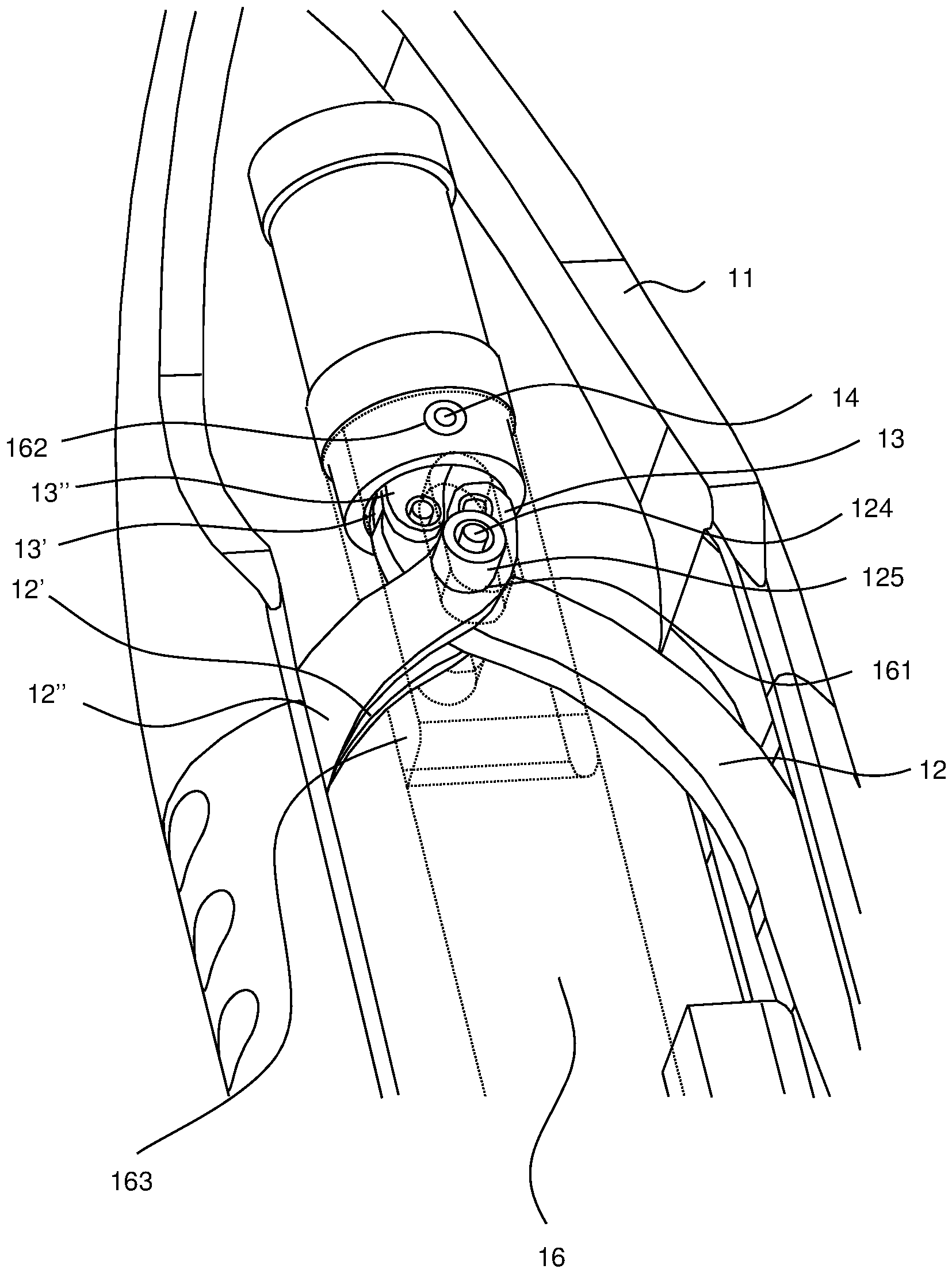
In der
In der
An beiden Enden des Achsstifts
Ferner ist eine Ausnehmung
BezugszeichenlisteLIST OF REFERENCE NUMBERS
- 11
- Betätigungsgriffoperating handle
- 1'1'
- Proximales Ende des BetätigungsgriffsProximal end of the operating handle
- 1"1"
- Distales Ende des BetätigungsgriffsDistal end of the operating handle
- 1111
- Griffteilhandle part
- 111111
- Proximales Ende des GriffteilsProximal end of the grip part
- 112112
- Distales Ende des GriffteilsDistal end of the handle
- 113113
- Anschlagpunkt des ersten Hebels am GriffteilLifting point of the first lever on the handle
- 1212
- Erster HebelFirst lever
- 12'12 '
- Erste Hebelhälfte des ersten HebelsFirst lever half of the first lever
- 12"12 "
- Zweite Hebelhälfte des ersten HebelsSecond lever half of the first lever
- 121121
- Dem Griffteil abgewandtes Ende des ersten HebelsThe handle part facing away from the first lever
- 122122
- Kreuzungspunkt der ersten HebelCrossing point of the first lever
- 123123
- Dem Griffteil zugewandtes Ende des ersten HebelsThe handle part facing the end of the first lever
- 124124
- Achsstiftaxle pin
- 125125
- Führungsrolleleadership
- 126126
- Bohrung am KreuzungspunktBore at the crossing point
- 1313
- Zweiter HebelSecond lever
- 13'13 '
- Erste Hebelhälfte des zweiten HebelsFirst lever half of the second lever
- 13"13 "
- Zweite Hebelhälfte des zweiten HebelsSecond lever half of the second lever
- 131131
- Dem ersten Hebel abgewandtes Ende des zweiten HebelsThe first lever facing away from the second lever
- 132132
- Dem ersten Hebel zugewandtes Ende des zweiten HebelsThe first lever facing the end of the second lever
- 1414
- Führungsstiftguide pin
- 1515
- Äußerer SchaftOuter shaft
- 1616
- Innerer SchaftInner shaft
- 161161
- Langloch im inneren SchaftLong hole in the inner shaft
- 162162
- Ausnehmung des inneren Schafts zur Aufnahme des FührungsstiftsRecess of the inner shaft for receiving the guide pin
- 163163
- Durchstecköffnung des inneren Schafts für erste HebelThrough opening of the inner shaft for first lever
- 1717
- Verriegelungsvorrichtunglocking device
- 1818
- SchnellwechselvorrichtungQuick change device
Claims (9)
Priority Applications (5)
| Application Number | Priority Date | Filing Date | Title |
|---|---|---|---|
| DE102012110260.0A DE102012110260B4 (en) | 2012-10-26 | 2012-10-26 | Operating handle for a microsurgical instrument |
| GB1317825.6A GB2509211B (en) | 2012-10-26 | 2013-10-08 | Actuation grip for a microsurgical instrument, and microsurgical instrument |
| FR1360260A FR2997286B1 (en) | 2012-10-26 | 2013-10-22 | HANDLE FOR MICROSURGERY INSTRUMENT, AND INSTRUMENT EQUIPPED WITH SAID HANDLE |
| IT001760A ITMI20131760A1 (en) | 2012-10-26 | 2013-10-22 | DRIVE HANDLE FOR A MICRO SURGICAL INSTRUMENT AND MICROSURGERY INSTRUMENT. |
| US14/062,416 US9566081B2 (en) | 2012-10-26 | 2013-10-24 | Actuation grip for a microsurgical instrument, and microsurgical instrument |
Applications Claiming Priority (1)
| Application Number | Priority Date | Filing Date | Title |
|---|---|---|---|
| DE102012110260.0A DE102012110260B4 (en) | 2012-10-26 | 2012-10-26 | Operating handle for a microsurgical instrument |
Publications (2)
| Publication Number | Publication Date |
|---|---|
| DE102012110260A1 DE102012110260A1 (en) | 2014-04-30 |
| DE102012110260B4 true DE102012110260B4 (en) | 2018-10-11 |
Family
ID=49630395
Family Applications (1)
| Application Number | Title | Priority Date | Filing Date |
|---|---|---|---|
| DE102012110260.0A Active DE102012110260B4 (en) | 2012-10-26 | 2012-10-26 | Operating handle for a microsurgical instrument |
Country Status (5)
| Country | Link |
|---|---|
| US (1) | US9566081B2 (en) |
| DE (1) | DE102012110260B4 (en) |
| FR (1) | FR2997286B1 (en) |
| GB (1) | GB2509211B (en) |
| IT (1) | ITMI20131760A1 (en) |
Families Citing this family (2)
| Publication number | Priority date | Publication date | Assignee | Title |
|---|---|---|---|---|
| US20160302810A1 (en) * | 2015-04-16 | 2016-10-20 | Whitney Surgical Labs, LLC | Surgical Tool |
| EP3373831B1 (en) * | 2015-11-13 | 2024-01-03 | Intuitive Surgical Operations, Inc. | Push-pull stapler with two degree of freedom wrist |
Citations (4)
| Publication number | Priority date | Publication date | Assignee | Title |
|---|---|---|---|---|
| DE69532918T2 (en) | 1994-02-14 | 2004-09-02 | Heartport, Inc., Redwood City | ENDOSCOPIC, MICROSURGICAL INSTRUMENTS |
| WO2005072105A2 (en) | 2004-01-23 | 2005-08-11 | Ethicon, Inc. | Surgical clamp possessing a combined parallel and scissor style clamp head |
| EP1201193B1 (en) | 2000-10-19 | 2008-12-03 | Alcon Grieshaber AG | Surgical instrument |
| DE102010013916A1 (en) | 2010-04-01 | 2011-10-06 | Karl Storz Gmbh & Co. Kg | Medical instrument |
Family Cites Families (46)
| Publication number | Priority date | Publication date | Assignee | Title |
|---|---|---|---|---|
| CA925395A (en) * | 1969-07-04 | 1973-05-01 | Dbm Industries Limited | Stapler device |
| US5133727A (en) * | 1990-05-10 | 1992-07-28 | Symbiosis Corporation | Radial jaw biopsy forceps |
| US5020519A (en) * | 1990-12-07 | 1991-06-04 | Zimmer, Inc. | Sagittal approximator |
| US5201743A (en) * | 1992-05-05 | 1993-04-13 | Habley Medical Technology Corp. | Axially extendable endoscopic surgical instrument |
| US5282806A (en) * | 1992-08-21 | 1994-02-01 | Habley Medical Technology Corporation | Endoscopic surgical instrument having a removable, rotatable, end effector assembly |
| US5281235A (en) * | 1992-02-21 | 1994-01-25 | Habley Medical Technology Corporation | Needle manipulator |
| DE4210803C1 (en) * | 1992-04-01 | 1993-06-17 | Emka Beschlagteile Gmbh & Co Kg, 5620 Velbert, De | |
| US5251638A (en) * | 1992-04-16 | 1993-10-12 | Cordis Corporation | Biopsy forceps device having improved handle assembly |
| US5478351A (en) * | 1992-06-24 | 1995-12-26 | Microsurge, Inc. | Endoscopic surgical tool with handle and detachable tool assembly |
| US5308357A (en) * | 1992-08-21 | 1994-05-03 | Microsurge, Inc. | Handle mechanism for manual instruments |
| US5868761A (en) * | 1992-10-09 | 1999-02-09 | United States Surgical Corporation | Surgical clip applier |
| CA2133687C (en) * | 1992-10-09 | 2007-03-27 | David T. Green | Surgical clip applier |
| US5507773A (en) * | 1994-02-18 | 1996-04-16 | Ethicon Endo-Surgery | Cable-actuated jaw assembly for surgical instruments |
| DE19508186C2 (en) * | 1995-03-09 | 1998-01-15 | Stefan Koscher | Surgical instrument |
| US5893873A (en) * | 1995-10-23 | 1999-04-13 | Johns Hopkins University | Surgical instrument having a handle with a removable, rotatable tip |
| US6391039B1 (en) * | 1996-07-23 | 2002-05-21 | United States Surgical Corporation | Anastomosis instrument and method |
| US20020019642A1 (en) * | 1996-07-23 | 2002-02-14 | Keith Milliman | Anastomosis instrument and method for performing same |
| US7223273B2 (en) * | 1996-07-23 | 2007-05-29 | Tyco Healthcare Group Lp | Anastomosis instrument and method for performing same |
| US6083234A (en) * | 1996-07-23 | 2000-07-04 | Surgical Dynamics, Inc. | Anastomosis instrument and method |
| US6024748A (en) * | 1996-07-23 | 2000-02-15 | United States Surgical Corporation | Singleshot anastomosis instrument with detachable loading unit and method |
| US5891140A (en) * | 1996-12-23 | 1999-04-06 | Cardiothoracic Systems, Inc. | Electrosurgical device for harvesting a vessel especially the internal mammary artery for coronary artery bypass grafting |
| US6322578B1 (en) * | 1997-07-14 | 2001-11-27 | Heartport, Inc. | Endoscopic microsurgical instruments |
| US5954746A (en) * | 1997-10-09 | 1999-09-21 | Ethicon Endo-Surgery, Inc. | Dual cam trigger for a surgical instrument |
| US5928263A (en) * | 1998-02-02 | 1999-07-27 | Aslan Medical Technologies | Surgical instrument with flexible actuator and rigid actuator cover |
| US7578828B2 (en) * | 1999-01-15 | 2009-08-25 | Medtronic, Inc. | Methods and devices for placing a conduit in fluid communication with a target vessel |
| GB9919722D0 (en) * | 1999-08-20 | 1999-10-20 | Surgical Innovations Ltd | Laparoscopic forceps handle |
| US6533797B1 (en) * | 1999-11-24 | 2003-03-18 | Nuvasive | Control grip assembly |
| DE10293222B4 (en) * | 2001-07-21 | 2008-10-02 | Dausch Medizintechnik Gmbh | Pliers-like surgical element |
| US7195142B2 (en) * | 2003-05-30 | 2007-03-27 | Tyco Healthcare Group Lp | End-to-end anastomosis instrument and method for performing same |
| US6769594B2 (en) * | 2002-05-31 | 2004-08-03 | Tyco Healthcare Group, Lp | End-to-end anastomosis instrument and method for performing same |
| US7211092B2 (en) * | 2002-11-19 | 2007-05-01 | Pilling Weck Incorporated | Automated-feed surgical clip applier and related methods |
| US8905937B2 (en) * | 2009-02-26 | 2014-12-09 | Integrated Vascular Systems, Inc. | Methods and apparatus for locating a surface of a body lumen |
| US8979879B2 (en) * | 2004-08-10 | 2015-03-17 | Asico, Llc. | Nucleus chopper and splitter |
| US20060079933A1 (en) * | 2004-10-08 | 2006-04-13 | Dylan Hushka | Latching mechanism for forceps |
| DE102006007107B4 (en) * | 2006-02-16 | 2007-10-18 | Peter Lazic Gmbh | Pipe tongs with power transmission |
| WO2007098231A2 (en) * | 2006-02-21 | 2007-08-30 | Cook Incorporated | Implant retrieval assemby and method for retrieving an implant |
| US8182495B2 (en) * | 2009-07-21 | 2012-05-22 | Distefano James G | Suture tensioner with gauge |
| DE102010026305A1 (en) * | 2010-07-06 | 2012-01-12 | Deutsches Zentrum für Luft- und Raumfahrt e.V. | robot structure |
| US9084683B2 (en) * | 2011-01-07 | 2015-07-21 | Pbn Spinal Implants, Llc | Spinal implant system and method |
| JP5793618B2 (en) * | 2011-06-21 | 2015-10-14 | クック・メディカル・テクノロジーズ・リミテッド・ライアビリティ・カンパニーCook Medical Technologies Llc | Control system for stent delivery system |
| US9902032B2 (en) * | 2011-10-18 | 2018-02-27 | Phd, Inc. | Pin clamp with multi-thickness clamping feature |
| JP5883343B2 (en) * | 2012-04-12 | 2016-03-15 | 株式会社スズキプレシオン | Medical manipulator |
| US9468453B2 (en) * | 2013-05-03 | 2016-10-18 | Covidien Lp | Endoscopic surgical forceps |
| US9827141B2 (en) * | 2013-06-21 | 2017-11-28 | Novartis Ag | Systems and techniques for tissue manipulation during ocular surgery |
| US9248555B2 (en) * | 2013-09-03 | 2016-02-02 | Vernon James Ford, JR. | Locking V hinge tool device |
| DE102014115600A1 (en) * | 2014-10-27 | 2016-04-28 | Karl Storz Gmbh & Co. Kg | Surgical instrument with a manual control device |
-
2012
- 2012-10-26 DE DE102012110260.0A patent/DE102012110260B4/en active Active
-
2013
- 2013-10-08 GB GB1317825.6A patent/GB2509211B/en active Active
- 2013-10-22 IT IT001760A patent/ITMI20131760A1/en unknown
- 2013-10-22 FR FR1360260A patent/FR2997286B1/en active Active
- 2013-10-24 US US14/062,416 patent/US9566081B2/en active Active
Patent Citations (4)
| Publication number | Priority date | Publication date | Assignee | Title |
|---|---|---|---|---|
| DE69532918T2 (en) | 1994-02-14 | 2004-09-02 | Heartport, Inc., Redwood City | ENDOSCOPIC, MICROSURGICAL INSTRUMENTS |
| EP1201193B1 (en) | 2000-10-19 | 2008-12-03 | Alcon Grieshaber AG | Surgical instrument |
| WO2005072105A2 (en) | 2004-01-23 | 2005-08-11 | Ethicon, Inc. | Surgical clamp possessing a combined parallel and scissor style clamp head |
| DE102010013916A1 (en) | 2010-04-01 | 2011-10-06 | Karl Storz Gmbh & Co. Kg | Medical instrument |
Also Published As
| Publication number | Publication date |
|---|---|
| GB2509211A (en) | 2014-06-25 |
| GB2509211B (en) | 2019-01-16 |
| US20140121692A1 (en) | 2014-05-01 |
| FR2997286B1 (en) | 2019-08-09 |
| ITMI20131760A1 (en) | 2014-04-27 |
| FR2997286A1 (en) | 2014-05-02 |
| GB201317825D0 (en) | 2013-11-20 |
| US9566081B2 (en) | 2017-02-14 |
| DE102012110260A1 (en) | 2014-04-30 |
Similar Documents
| Publication | Publication Date | Title |
|---|---|---|
| EP1453415B1 (en) | Endoscope | |
| DE19912038C1 (en) | Handle for a medical instrument | |
| DE69218688T2 (en) | Pliers | |
| EP2510888B1 (en) | Handling device for a micro-invasive surgical instrument | |
| DE19707373C1 (en) | Releasable connection of two tube shaft instruments or instrument parts | |
| EP1839604B1 (en) | Device for performing examinations and surgical operations on the uterus | |
| EP2249715B1 (en) | Surgical instrument which can be disassembled | |
| EP2904978B1 (en) | Retractor and operating method | |
| DE4323809A1 (en) | Surgical instrument with pair of circular grip parts - has pair of relatively movable working elements at distal end, and actuator | |
| DE69223382T2 (en) | Endoscopic surgical instruments and jaw structure | |
| DE102011007119A1 (en) | Handling device for a micro-invasive-surgical instrument | |
| EP3351192A2 (en) | Surgical instrument, in particular for neurosurgery | |
| EP1488749A1 (en) | Medical instrument | |
| EP1750599B9 (en) | Grip element for a surgical instrument | |
| DE102010054333B4 (en) | Surgical retractor | |
| DE102012110260B4 (en) | Operating handle for a microsurgical instrument | |
| EP1701661B1 (en) | Medical cutting and/or holding instrument | |
| DE10341561B4 (en) | Medical device | |
| DE102010033424B4 (en) | Endoscopic instrument | |
| EP1629785B1 (en) | Medical forceps | |
| DE202007000427U1 (en) | Surgical handle and surgical instrument | |
| DE202009003255U1 (en) | Trocar guide sleeve and trocar system | |
| DE102007001752B4 (en) | Surgical handle and surgical instrument | |
| EP3503820A1 (en) | Surgical jaw-type instrument comprising a counterbalanced lever system | |
| DE102007001749B4 (en) | Surgical instrument |
Legal Events
| Date | Code | Title | Description |
|---|---|---|---|
| R163 | Identified publications notified | ||
| R012 | Request for examination validly filed | ||
| R081 | Change of applicant/patentee |
Owner name: KARL STORZ SE & CO. KG INTELLECTUAL PROPERTY, DE Free format text: FORMER OWNER: KARL STORZ GMBH & CO. KG, 78532 TUTTLINGEN, DE Owner name: KARL STORZ SE & CO. KG, DE Free format text: FORMER OWNER: KARL STORZ GMBH & CO. KG, 78532 TUTTLINGEN, DE |
|
| R016 | Response to examination communication | ||
| R018 | Grant decision by examination section/examining division | ||
| R020 | Patent grant now final |