DE102012103425A1 - Microwave plasma generating device and method of operation thereof - Google Patents
Microwave plasma generating device and method of operation thereof Download PDFInfo
- Publication number
- DE102012103425A1 DE102012103425A1 DE102012103425A DE102012103425A DE102012103425A1 DE 102012103425 A1 DE102012103425 A1 DE 102012103425A1 DE 102012103425 A DE102012103425 A DE 102012103425A DE 102012103425 A DE102012103425 A DE 102012103425A DE 102012103425 A1 DE102012103425 A1 DE 102012103425A1
- Authority
- DE
- Germany
- Prior art keywords
- plasma
- microwave
- chamber
- generating device
- microwave plasma
- Prior art date
- Legal status (The legal status is an assumption and is not a legal conclusion. Google has not performed a legal analysis and makes no representation as to the accuracy of the status listed.)
- Withdrawn
Links
Images


Classifications
-
- H—ELECTRICITY
- H01—ELECTRIC ELEMENTS
- H01J—ELECTRIC DISCHARGE TUBES OR DISCHARGE LAMPS
- H01J37/00—Discharge tubes with provision for introducing objects or material to be exposed to the discharge, e.g. for the purpose of examination or processing thereof
- H01J37/32—Gas-filled discharge tubes
- H01J37/32009—Arrangements for generation of plasma specially adapted for examination or treatment of objects, e.g. plasma sources
- H01J37/32192—Microwave generated discharge
- H01J37/32211—Means for coupling power to the plasma
- H01J37/3222—Antennas
-
- H—ELECTRICITY
- H01—ELECTRIC ELEMENTS
- H01J—ELECTRIC DISCHARGE TUBES OR DISCHARGE LAMPS
- H01J37/00—Discharge tubes with provision for introducing objects or material to be exposed to the discharge, e.g. for the purpose of examination or processing thereof
- H01J37/32—Gas-filled discharge tubes
- H01J37/32009—Arrangements for generation of plasma specially adapted for examination or treatment of objects, e.g. plasma sources
- H01J37/32192—Microwave generated discharge
- H01J37/32211—Means for coupling power to the plasma
- H01J37/32229—Waveguides
-
- H—ELECTRICITY
- H01—ELECTRIC ELEMENTS
- H01J—ELECTRIC DISCHARGE TUBES OR DISCHARGE LAMPS
- H01J37/00—Discharge tubes with provision for introducing objects or material to be exposed to the discharge, e.g. for the purpose of examination or processing thereof
- H01J37/32—Gas-filled discharge tubes
- H01J37/32431—Constructional details of the reactor
- H01J37/32532—Electrodes
- H01J37/32568—Relative arrangement or disposition of electrodes; moving means
-
- H—ELECTRICITY
- H01—ELECTRIC ELEMENTS
- H01J—ELECTRIC DISCHARGE TUBES OR DISCHARGE LAMPS
- H01J37/00—Discharge tubes with provision for introducing objects or material to be exposed to the discharge, e.g. for the purpose of examination or processing thereof
- H01J37/32—Gas-filled discharge tubes
- H01J37/32431—Constructional details of the reactor
- H01J37/3266—Magnetic control means
- H01J37/32669—Particular magnets or magnet arrangements for controlling the discharge
-
- H—ELECTRICITY
- H05—ELECTRIC TECHNIQUES NOT OTHERWISE PROVIDED FOR
- H05H—PLASMA TECHNIQUE; PRODUCTION OF ACCELERATED ELECTRICALLY-CHARGED PARTICLES OR OF NEUTRONS; PRODUCTION OR ACCELERATION OF NEUTRAL MOLECULAR OR ATOMIC BEAMS
- H05H1/00—Generating plasma; Handling plasma
- H05H1/24—Generating plasma
- H05H1/46—Generating plasma using applied electromagnetic fields, e.g. high frequency or microwave energy
-
- H—ELECTRICITY
- H01—ELECTRIC ELEMENTS
- H01J—ELECTRIC DISCHARGE TUBES OR DISCHARGE LAMPS
- H01J2237/00—Discharge tubes exposing object to beam, e.g. for analysis treatment, etching, imaging
- H01J2237/32—Processing objects by plasma generation
- H01J2237/33—Processing objects by plasma generation characterised by the type of processing
- H01J2237/332—Coating
- H01J2237/3321—CVD [Chemical Vapor Deposition]
-
- H—ELECTRICITY
- H05—ELECTRIC TECHNIQUES NOT OTHERWISE PROVIDED FOR
- H05H—PLASMA TECHNIQUE; PRODUCTION OF ACCELERATED ELECTRICALLY-CHARGED PARTICLES OR OF NEUTRONS; PRODUCTION OR ACCELERATION OF NEUTRAL MOLECULAR OR ATOMIC BEAMS
- H05H1/00—Generating plasma; Handling plasma
- H05H1/24—Generating plasma
- H05H1/46—Generating plasma using applied electromagnetic fields, e.g. high frequency or microwave energy
- H05H1/461—Microwave discharges
- H05H1/463—Microwave discharges using antennas or applicators
-
- H—ELECTRICITY
- H05—ELECTRIC TECHNIQUES NOT OTHERWISE PROVIDED FOR
- H05H—PLASMA TECHNIQUE; PRODUCTION OF ACCELERATED ELECTRICALLY-CHARGED PARTICLES OR OF NEUTRONS; PRODUCTION OR ACCELERATION OF NEUTRAL MOLECULAR OR ATOMIC BEAMS
- H05H1/00—Generating plasma; Handling plasma
- H05H1/24—Generating plasma
- H05H1/46—Generating plasma using applied electromagnetic fields, e.g. high frequency or microwave energy
- H05H1/461—Microwave discharges
- H05H1/4637—Microwave discharges using cables
Landscapes
- Physics & Mathematics (AREA)
- Engineering & Computer Science (AREA)
- Plasma & Fusion (AREA)
- Chemical & Material Sciences (AREA)
- Analytical Chemistry (AREA)
- Electromagnetism (AREA)
- Spectroscopy & Molecular Physics (AREA)
- Chemical Vapour Deposition (AREA)
- Plasma Technology (AREA)
- Drying Of Semiconductors (AREA)
- Physical Or Chemical Processes And Apparatus (AREA)
Abstract
Die vorliegende Erfindung beinhaltet eine Mikrowellenplasmaerzeugungsvorrichtung mit einer Plasmakammer. Außerhalb der Plasmakammer ist wenigstens eine Mikrowellenerzeugungsvorrichtung vorgesehen, deren Mikrowellen über wenigstens eine Mikrowelleneinkoppelvorrichtung in die Plasmakammer eingekoppelt werden. Die Mikrowelleneinkoppelvorrichtung weist einen durch wenigstens eine Kammerwand der Plasmakammer in die Plasmakammer führenden Innenleiter, ein den Innenleiter einschließendes und den Innenleiter von einem Innenraum der Plasmakammer abtrennendes Isolierrohr und wenigstens einen durch die wenigstens eine Kammerwand in die Plasmakammer führenden, koaxial, aber nicht vollumfänglich um den gesamten Innenleiter vorgesehenen Außenleiter auf. Der Außenleiter besitzt in der Plasmakammer wenigstens ein Außenleiter-Ende. Der Innenleiter und der Außenleiter bilden eine Mikrowellenleitung aus, wobei in der Plasmakammer ein Austritt von Mikrowellen aus der Mikrowellenleitung zur Erzeugung eines Mikrowellenplasmas in dem Innenraum der Plasmakammer vorgesehen ist. Erfindungsgemäß ist in dem Innenraum der Plasmakammer, koaxial zu dem Innenleiter wenigstens eine gegenüber der Kammerwand elektrisch isolierte und mit einer DC-, NF- oder HF-Spannung beaufschlagbare Plasmaelektrode vorgesehen, mit welcher das Mikrowellenplasma elektrisch kontaktierbar ist, sodass dem Mikrowellenplasma zumindest teilweise die Funktion des Außenleiters übertragbar ist. Die Erfindung betrifft ferner ein Verfahren zum Betreiben einer solchen Mikrowellenplasmaerzeugungsvorrichtung.The present invention includes a microwave plasma generating device having a plasma chamber. Outside the plasma chamber, at least one microwave generating device is provided, the microwaves of which are coupled into the plasma chamber via at least one microwave coupling device. The microwave coupling device has an inner conductor leading through at least one chamber wall of the plasma chamber into the plasma chamber, an insulating tube enclosing the inner conductor and separating the inner conductor from an interior of the plasma chamber and at least one coaxially, but not fully, around the at least one chamber wall into the plasma chamber entire inner conductor provided on outer conductor. The outer conductor has at least one outer conductor end in the plasma chamber. The inner conductor and the outer conductor form a microwave line, wherein an exit of microwaves from the microwave line for generating a microwave plasma in the interior of the plasma chamber is provided in the plasma chamber. According to the invention, at least one plasma electrode which is electrically insulated from the chamber wall and can be acted upon by a DC, NF or HF voltage is provided in the interior of the plasma chamber, with which the microwave plasma is electrically contactable, so that the function of the microwave plasma is at least partially the external conductor is transferable. The invention further relates to a method of operating such a microwave plasma generating device.
Description
Die vorliegende Erfindung betrifft eine Mikrowellenplasmaerzeugungsvorrichtung mit einer Plasmakammer, wenigstens einer außerhalb der Plasmakammer vorgesehenen Mikrowellenerzeugungsvorrichtung zur Erzeugung von Mikrowellen und einer Mikrowelleneinkoppelvorrichtung, mit der die Mikrowellen in die Plasmakammer einkoppelbar sind, wobei die Mikrowelleneinkoppelvorrichtung einen durch wenigstens eine Kammerwand der Plasmakammer in die Plasmakammer führenden Innenleiter, ein den Innenleiter einschließendes und den Innenleiter von einem Innenraum der Plasmakammer abtrennendes Isolierrohr und einen durch die wenigstens eine Kammerwand in die Plasmakammer führenden, koaxial, aber nicht um den gesamten Umfang des Innenleiters vorgesehenen und in der Plasmakammer wenigstens ein Außenleiter-Ende aufweisenden Außenleiter aufweist, wobei der Innenleiter und der Außenleiter eine Mikrowellenleitung ausbilden und in der Plasmakammer ein Austritt von Mikrowellen aus der Mikrowellenleitung zur Erzeugung eines Mikrowellenplasmas in dem Innenraum der Plasmakammer vorgesehen ist. Die Erfindung betrifft ferner ein Verfahren zum Betreiben einer solchen Mikrowellenplasmaerzeugungsvorrichtung. The present invention relates to a microwave plasma generating device comprising a plasma chamber, at least one microwave generating device provided outside the plasma chamber for generating microwaves and a microwave coupling device with which the microwaves can be coupled into the plasma chamber, the microwave coupling device having an inner conductor leading into the plasma chamber through at least one chamber wall of the plasma chamber , an insulating tube enclosing the inner conductor and separating the inner conductor from an inner space of the plasma chamber and an outer conductor leading through the at least one chamber wall into the plasma chamber, but not coaxially provided around the entire circumference of the inner conductor and having at least one outer conductor end in the plasma chamber in which the inner conductor and the outer conductor form a microwave line and in the plasma chamber an exit of microwaves from the microwave line to the ore Diffusion of a microwave plasma is provided in the interior of the plasma chamber. The invention further relates to a method of operating such a microwave plasma generating device.
Mikrowellenplasmaerzeugungsvorrichtungen der genannten Gattung sind aus dem Stand der Technik beispielsweise aus der Druckschrift
Mit einer solchen Mikrowellenplasmaerzeugungsvorrichtung können durch die hohe erzeugbare Plasmadichte effektive Plasmabearbeitungen durchgeführt werden. Die Mikrowellenplasmaerzeugungsvorrichtungen können gepulst oder kontinuierlich betrieben werden. Bei einer Pulsung der Mikrowellenleistung können die Pulse sowohl phasengleich oder auch definiert phasenversetzt zueinander eingestellt werden. With such a microwave plasma generating apparatus, effective plasma processing can be performed by the high plasma density that can be generated. The microwave plasma generating devices may be pulsed or continuously operated. With a pulsation of the microwave power, the pulses can be adjusted both in phase or defined in phase with each other.
Beispielsweise können plasmaunterstützte CVD-Abscheidungen mit hohen Abscheideraten realisiert werden. Typisch für plasmagestützte CVD-Abscheidungen mit Mikrowellenplasmen ist, dass die Ionenenergie der auf die Schicht einwirkenden Ionen relativ gering ist. Das kann bei sensiblen Substratoberflächen sehr vorteilhaft sein, führt aber mitunter zu einer geringeren Schichtqualität zum Beispiel dann, wenn bei hohen Abscheideraten gleichzeitig sehr dichte Schichten erreicht werden sollen. Eine bekannte Möglichkeit zur Steigerung der Schichtdichte besteht in der Erhöhung der Ionenenergien durch eine die Ionen beschleunigende elektrische Substratvorspannung. Allerdings erweist sich die zuverlässige Einstellung der gewünschten Substratvorspannung in der Praxis insbesondere bei bewegten Substratträgern und Substraten als schwierig. For example, plasma enhanced CVD depositions can be realized with high deposition rates. Typical of plasma-enhanced CVD deposition with microwave plasmas is that the ion energy of the ions acting on the layer is relatively low. This can be very advantageous for sensitive substrate surfaces, but sometimes leads to a lower layer quality, for example, when at high deposition rates very dense layers are to be achieved simultaneously. A known possibility for increasing the layer density consists in the increase of the ion energies by an ion-accelerating electrical substrate bias. However, the reliable setting of the desired substrate bias proves difficult in practice, especially with moving substrate carriers and substrates.
Es ist daher die Aufgabe der Erfindung, ein einfaches Verfahren zur Abscheidung qualitativ hochwertiger Schichten bei einer hohen Abscheiderate und eine entsprechende Anlagentechnik zur Ausführung dieses Verfahrens vorzuschlagen. It is therefore the object of the invention to propose a simple method for depositing high-quality layers at a high deposition rate and a corresponding system technology for carrying out this method.
Die Aufgabe wird in einem Aspekt der Erfindung durch eine Mikrowellenplasmaerzeugungsvorrichtung der eingangs genannten Gattung gelöst, wobei in dem Innenraum der Plasmakammer, koaxial zu dem Innenleiter wenigstens eine gegenüber der Kammerwand elektrisch isolierte und mit einer DC-, NF- oder HF-Spannung beaufschlagbare Plasmaelektrode vorgesehen ist, mit welcher das Mikrowellenplasma elektrisch kontaktierbar ist, sodass dem Mikrowellenplasma zumindest teilweise die Funktion des Außenleiters übertragbar ist. Dabei wird erfindungsgemäß unter einer DC-Spannung eine Gleichspannung, unter einer NF-Spannung eine niederfrequente Spannung, das heißt eine Spannung mit einer Frequenz von 20 bis 20000 Hz, und unter einer HF-Spannung eine hochfrequente Spannung, das heißt eine Spannung einer Frequenz von 3 MHz bis ca. 300 GHz, verstanden. The object is achieved in one aspect of the invention by a microwave plasma generating device of the type mentioned, wherein provided in the interior of the plasma chamber, coaxial with the inner conductor at least one with respect to the chamber wall electrically isolated and acted upon by a DC, NF or HF voltage plasma electrode is, with which the microwave plasma is electrically contacted, so that the microwave plasma at least partially the function of the outer conductor is transferable. According to the invention, under a DC voltage, a DC voltage, below a low-frequency voltage, a low-frequency voltage, that is a voltage having a frequency of 20 to 20,000 Hz, and under an RF voltage, a high-frequency voltage, that is, a voltage of a frequency of 3 MHz to about 300 GHz, understood.
Der Außenleiter einer mit großen elektrischen Leistungen betriebenen Mikrowellenleitung ist vorzugsweise elektrisch geerdet. Durch die Erdung werden ein einfacher technischer Aufbau und eine große Betriebssicherheit der erfindungsgemäßen Mikrowellenplasmaerzeugungsvorrichtung erreicht. The outer conductor of a microwave line operated with large electrical powers is preferably electrically grounded. By grounding a simple technical structure and a high reliability of the microwave plasma generating device according to the invention are achieved.
In der erfindungsgemäßen Mikrowellenplasmaerzeugungsvorrichtung endet der Außenleiter im Inneren der Plasmakammer an dem wenigstens einen Außenleiter-Ende. An das Außenleiter-Ende anschließend ist das Mikrowellenplasma als elektrischer Leiter vorgesehen, wobei das Mikrowellenplasma die Aufgabe des Außenleiters bei der Mikrowellenleitung zumindest teilweise übernimmt. Das Außenleiter-Ende kann um den gesamten Umfang der Mikrowelleneinkoppelvorrichtung oder nur um einen Teil des Umfangs der Mikrowelleneinkoppelvorrichtung vorgesehen sein. Jedenfalls ist ab dem Außenleiter-Ende der Außenleiter zumindest teilweise unterbrochen, sodass in dem unterbrochenen Bereich durch den Außenleiter selbst keine Abschirmung mehr zur Verfügung gestellt wird, die ein Austreten von Mikrowellen aus dem Innenleiter in den Innenraum der Plasmakammer verhindern könnte. Das Mikrowellenplasma dient nach dem Außenleiter-Ende in der linearen Mikrowellenplasmaerzeugungsvorrichtung als Ersatz für den dort fehlenden Außenleiter. In the microwave plasma generating device according to the present invention, the outer conductor terminates inside the plasma chamber at the at least one outer conductor end. Subsequently, the microwave plasma is provided as an electrical conductor to the outer conductor end, wherein the microwave plasma at least partially takes over the task of the outer conductor in the microwave line. The outer conductor end may be provided around the entire circumference of the microwave coupling device or only around a part of the circumference of the microwave coupling device. In any case, at least partially interrupted from the outer conductor end of the outer conductor, so that in the interrupted area by the outer conductor itself no shielding is provided, which could prevent leakage of microwaves from the inner conductor in the interior of the plasma chamber. The microwave plasma is used after the outer conductor end in the linear microwave plasma generating device as a replacement for the missing there outer conductor.
Letzteres geschieht dadurch, dass dann, wenn das Plasma der erfindungsgemäßen Mikrowellenerzeugungsvorrichtung die Cut-Off-Dichte erreicht, dieses Plasma zum hochleitfähigen Koaxial-Außenleiter der Mikrowellenerzeugungsvorrichtung wird. Wenn dieses hochdichte Plasma isoliert zu einer möglichen „Masse“-Umgebung angeordnet wird, kann dieses Plasma als neue Elektrode für ein Niederdruckplasma verwendet werden. Dafür ist bei der erfindungsgemäßen Mikrowellenplasmaerzeugungsvorrichtung die Verschlusstechnik am Isolierrohr der Mikrowellenerzeugungsvorrichtung isoliert gegenüber Masse aufgebaut und die Plasmaelektrode, die der Kontaktierung des Mikrowellenplasmas dient, mit einer äußeren Spannungsquelle verbunden. The latter happens because when the plasma of the microwave generating device according to the invention reaches the cut-off density, this plasma becomes the highly conductive coaxial outer conductor of the microwave generating device. When this high density plasma is isolated to a possible "ground" environment, this plasma can be used as a new electrode for a low pressure plasma. For this purpose, in the microwave plasma generating device according to the invention, the closure technique is insulated from the insulating tube of the microwave generating device and the plasma electrode, which serves to contact the microwave plasma, is connected to an external voltage source.
Jedes erzeugte Plasma bildet zu den mit ihm in Wechselwirkung stehenden beziehungsweise einschließenden Wänden ein Plasmarandschichtpotenzial aus. Die Plasmaelektrode kann deshalb keinen wirklichen ohmschen Kontakt zum Mikrowellenplasma ausbilden. Es ist deshalb wichtig, dass die koppelnde Plasmaelektrodenfläche ausreichend groß bemessen wird, um einen gewünschten Ladungsträgerstrom zum Substrat einstellen zu können. Each generated plasma forms a plasma sand layer potential to the walls interacting with it or enclosing it. The plasma electrode can therefore not form a real ohmic contact with the microwave plasma. It is therefore important that the coupling plasma electrode surface be sized sufficiently large to be able to set a desired carrier current to the substrate.
Die Plasmaelektrode ist bei der erfindungsgemäßen Mikrowellenerzeugungsvorrichtung um den Außenleiter, in der Nähe des Außenleiter-Endes vorgesehen. Diese Plasmaelektrode ist gegenüber der Kammerwand und gegenüber dem Außenleiter elektrisch isoliert und kann mit einer DC-, NF- oder HF-Spannung beaufschlagt werden. In der erfindungsgemäßen Mikrowellenplasmaerzeugungsvorrichtung werden somit die elektrischen Eigenschaften des Mikrowellenplasmas nicht nur durch die über die Mikrowellenleitung eingeleiteten Mikrowellen, sondern auch über die an die Plasmaelektrode angelegte DC-, NF- oder HF-Spannung bestimmt. The plasma electrode is provided in the microwave generating device according to the invention around the outer conductor, in the vicinity of the outer conductor end. This plasma electrode is electrically insulated from the chamber wall and from the outer conductor and can be supplied with a DC, NF or HF voltage. In the microwave plasma generating device according to the invention, therefore, the electrical properties of the microwave plasma are determined not only by the microwaves introduced via the microwave line but also by the DC, NF or HF voltage applied to the plasma electrode.
Als Spannungsversorgungen der Plasmaelektroden können Gleichspannungen oder Wechselspannungen verwendet werden. Die Spannungsversorgungen können dabei entweder kontinuierlich oder gepulst betrieben werden. Der Frequenzbereich der Wechselspannungen liegt vorteilhaft zwischen ca. 50 Hz und 13,56 MHz. Die konkrete Auswahl erfolgt dabei nach den technologischen Erfordernissen und ist nicht auf den angegebenen Frequenzbereich beschränkt. Bei bestimmten Anwendungen kann es vorteilhaft sein, wenn auch die Mikrowellenerzeugungsvorrichtungen und die Spannungsversorgungen der Plasmaelektrode zeitlich zueinander definiert betrieben werden können. Damit kann zum Beispiel in zeitlicher Abfolge der Substratbearbeitung ein Ionenbeschuss mit hoher Ionenenergie oder mit niedriger Ionenenergie eingestellt werden. DC voltages or AC voltages can be used as voltage supplies of the plasma electrodes. The power supplies can be operated either continuously or pulsed. The frequency range of the alternating voltages is advantageously between about 50 Hz and 13.56 MHz. The concrete selection is made according to the technological requirements and is not limited to the specified frequency range. In certain applications, it may be advantageous if the microwave generation devices and the power supplies of the plasma electrode can be operated in a timely manner with respect to each other. Thus, for example, in time sequence of the substrate processing, ion bombardment with high ion energy or with low ion energy can be set.
Bei herkömmlichen, aus dem Stand der Technik bekannten Mikrowellenplasmaerzeugungsvorrichtungen schließt sich das Mikrowellenplasma meist direkt an den geerdeten Außenleiter an beziehungsweise steht in intensiver Wechselwirkung mit umliegenden Wänden, die sich auf Erdpotenzial befinden, und weist deshalb auch selbst ein Potenzial in der Nähe des Erdpotenzials auf. Dadurch kann das Mikrowellenplasma, selbst mit einer zusätzlichen Plasmaelektrode, nicht auf ein höheres Plasmapotenzial angehoben werden. Erfindungsgemäß wird dieser Nachteil dadurch behoben, dass das Mikrowellenplasma konsequent von umgebenden und geerdeten Wänden isoliert wird und dann an die Plasmaelektrode eine DC-, NF- oder HF-Spannung angelegt wird, sodass die Potenzialdifferenz zwischen Mikrowellenplasma und Substrat vergrößert wird und Ionen aus dem Mikrowellenplasma mit größerer Energie auf die Substrate auftreffen. Die damit einstellbare Ionenenergie erlaubt beispielsweise eine Erhöhung der Schichtdichte der abgeschiedenen Schichten und ermöglicht die Überwindung energetischer Barrieren bei Ausheilvorgängen in der Schicht. Die Plasmaelektrode ist ein stationärer Bestandteil der erfindungsgemäßen Mikrowellenplasmaerzeugungsvorrichtung. Die Plasmaelektrode kann deshalb einfach und zuverlässig elektrisch angeschlossen werden. In conventional microwave plasma generating devices known from the prior art, the microwave plasma usually directly adjoins the grounded outer conductor or is in intensive interaction with surrounding walls, which are at ground potential, and therefore itself has a potential in the vicinity of the ground potential. As a result, the microwave plasma, even with an additional plasma electrode, can not be raised to a higher plasma potential. According to the invention, this disadvantage is eliminated by consistently isolating the microwave plasma from surrounding and grounded walls and then applying a DC, NF or RF voltage to the plasma electrode so that the potential difference between the microwave plasma and the substrate is increased and ions from the microwave plasma hit the substrates with greater energy. The thus adjustable ion energy allows, for example, an increase in the layer density of the deposited layers and allows the overcoming of energy barriers during annealing processes in the layer. The plasma electrode is a stationary component of the microwave plasma generating device according to the invention. The plasma electrode can therefore be easily and reliably connected electrically.
Mit der Plasmaelektrode wird ein ähnlicher technischer Effekt wie mit einer Substratvorspannung erzielt, die Lösung mit der Plasmaelektrode ist jedoch zuverlässiger und zudem einfach. The plasma electrode achieves a similar technical effect to a substrate bias, but the solution with the plasma electrode is more reliable and also simple.
Das erfindungsgemäß verwendete Mikrowellenplasma zeichnet sich durch eine einfache lineare Skalierbarkeit aus. Gegenüber niederfrequenteren Anregungsfrequenzen können Mikrowellen-Plasmen sehr hohe Plasmadichten erreichen und sind deshalb besonders für Hochrateprozesse geeignet. Zudem ist es durch die erfindungsgemäße Überlagerung des Mikrowellenplasmas mit einer Niederfrequenz- oder Hochfrequenzentladung möglich, gegenüber der Bezugsmasse ein variierbares Randschichtpotenzial einzustellen. Damit kann die Energie stoßender Ionen mit der Substratoberfläche in einem gewissen Umfang frei eingestellt werden. Da das gebildete Mikrowellenplasma der erfindungsgemäßen Mikrowellenplasmaerzeugungsvorrichtung immer am Außendurchmesser der Mikrowelleneinkoppelvorrichtung erzeugt wird, ist auch immer eine hochleitfähige Elektrode vorhanden, die die Rolle einer neuen Elektrode gegenüber der Bezugsmasse übernehmen kann. Das ist auch dann so, wenn isolierende Beschichtungen am dielektrischen Isolierrohr der Mikrowellenkoppelvorrichtung aufwachsen. The microwave plasma used according to the invention is characterized by a simple linear scalability. Compared to lower frequency excitation frequencies, microwave Plasmas reach very high plasma densities and are therefore particularly suitable for high-rate processes. In addition, it is possible by the superposition of the microwave plasma according to the invention with a low-frequency or high-frequency discharge to set a variable edge layer potential with respect to the reference ground. Thus, the energy of impinging ions can be freely adjusted with the substrate surface to a certain extent. Since the formed microwave plasma of the microwave plasma generating device according to the invention is always generated at the outer diameter of the Mikrowelleneinkoppelvorrichtung, also always a highly conductive electrode is present, which can take over the role of a new electrode relative to the reference ground. This is also the case when insulating coatings grow on the dielectric insulating tube of the microwave coupling device.
Vorzugsweise ist in der erfindungsgemäßen Mikrowellenplasmaerzeugungsvorrichtung, die als eine lineare Plasmaquelle ausgebildet ist, der wenigstens eine Außenleiter im Bereich der Kammerwand geerdet. Die Kammerwand und der Außenleiter können somit aus Metallen, welche geerdet sind, bestehen. Für die erfindungsgemäße Mikrowellenplasmaerzeugungsvorrichtung ergibt sich ein besonders einfacher Aufbau, wenn die Verbindungsstelle des Außenleiters mit der Kammerwand auf Erdpotenzial liegt. Der Außenleiter kann in diesem Fall einfach montiert werden, beispielsweise mit Hilfe einer Schweiß- oder Schraubverbindung. Der Außenleiter muss jedoch nicht unbedingt im Bereich der Kammerwand geerdet sein, der Außenleiter kann beispielsweise auch gegenüber einer leitenden Kammerwand isoliert oder in einer isolierenden Kammerwand befestigt sein. Preferably, in the microwave plasma generating device according to the invention, which is designed as a linear plasma source, the at least one outer conductor is earthed in the region of the chamber wall. The chamber wall and the outer conductor can thus consist of metals which are grounded. For the microwave plasma generating device according to the invention, a particularly simple structure results when the junction of the outer conductor with the chamber wall is at ground potential. The outer conductor can be easily mounted in this case, for example by means of a welded or screwed connection. However, the outer conductor does not necessarily have to be earthed in the region of the chamber wall, for example the outer conductor can also be insulated from a conductive chamber wall or fixed in an insulating chamber wall.
In einer anderen Variante der erfindungsgemäßen Mikrowellenplasmaerzeugungsvorrichtung kann der Außenleiter auch mit einer Spannungsversorgung verbunden sein. Dabei müsste der Außenleiter mit einer Wechselspannung höherer Frequenz versorgt und sonst gegenüber Masse isoliert werden. In diesem Fall könnte über den innerhalb des Isolierrohres befindlichen Außenleiter eine dielektrische Kopplung des Mikrowellenplasmas erfolgen. Dabei würde der wenigstens eine Außenleiter die erfindungsgemäße Funktion der Plasmaelektrode erfüllen und die Plasmaelektroden könnten grundsätzlich entfallen. In another variant of the microwave plasma generating device according to the invention, the outer conductor can also be connected to a power supply. In this case, the outer conductor would have to be supplied with an alternating voltage of higher frequency and otherwise isolated from ground. In this case, a dielectric coupling of the microwave plasma could take place via the outer conductor located inside the insulating tube. In this case, the at least one outer conductor would fulfill the function of the plasma electrode according to the invention and the plasma electrodes could basically be dispensed with.
In einer vorteilhaften Ausbildung der erfindungsgemäßen Mikrowellenplasmaerzeugungsvorrichtung ist der wenigstens eine Außenleiter innerhalb des Isolierrohres angeordnet. Die Plasmakammer muss regelmäßig gegenüber der Umwelt abgeschlossen betrieben werden. Das heißt, die Plasmakammer muss auch im Bereich der Mikrowellenleitung abgedichtet werden. Das Isolierrohr ist eine vorteilhafte Lösung für eine solche Abdichtung. Rohre sind generell stabile Bauelemente bei mechanischer Belastung durch Druckdifferenzen von innen nach außen und folglich für den Einsatz in der erfindungsgemäßen Mikrowellenplasmaerzeugungsvorrichtung gut geeignet. In an advantageous embodiment of the microwave plasma generating device according to the invention, the at least one outer conductor is arranged inside the insulating tube. The plasma chamber must be operated regularly against the environment. This means that the plasma chamber must also be sealed in the area of the microwave line. The insulating tube is an advantageous solution for such a seal. Tubes are generally stable components under mechanical stress due to pressure differences from the inside to the outside and thus well suited for use in the microwave plasma generating device according to the invention.
Durch die Anordnung des Außenleiters innerhalb des Isolierrohres ist dieser von dem Mikrowellenplasma räumlich getrennt und es findet keine Schichtabscheidung oder sonstige Plasmaeinwirkung auf den Außenleiter statt. Das Isolierrohr wirkt in dieser Lösung als räumliche Trennung und gleichzeitig als Austrittsfenster für die Mikrowellen von dem Inneren des Isolierrohres in den außerhalb des Isolierrohres befindlichen Innenraum der Plasmakammer. The arrangement of the outer conductor within the insulating tube, this is spatially separated from the microwave plasma and there is no deposition of layers or other plasma action on the outer conductor instead. The insulating tube acts in this solution as a spatial separation and at the same time as an exit window for the microwaves from the interior of the insulating tube in the outside of the insulating tube located inside the plasma chamber.
Gemäß einer günstigen Variante der erfindungsgemäßen Mikrowellenplasmaerzeugungsvorrichtung ist das wenigstens eine Außenleiter-Ende ein gerades Rohrende. In dieser Ausbildung bildet das Mikrowellenplasma im Anschluss an das Außenleiter-Ende einen hohlzylinderförmigen Außenleiter um den Innenleiter herum aus. Das Mikrowellenplasma befindet sich also in diesem Fall nicht nur substratseitig gegenüber dem Innenleiter, sondern auch auf der dem Substrat abgewandten Seite des Innenleiters. Eine solche Mikrowellenplasmaerzeugungsvorrichtung ist beispielsweise in Plasmabearbeitungsprozessen von Vorteil, in denen eine lange Verweildauer von Gasmolekülen in dem Mikrowellenplasma vorteilhaft ist. According to a favorable variant of the microwave plasma generating device according to the invention, the at least one outer conductor end is a straight tube end. In this embodiment, the microwave plasma forms a hollow cylindrical outer conductor around the inner conductor following the outer conductor end. The microwave plasma is thus in this case not only on the substrate side with respect to the inner conductor, but also on the side facing away from the substrate of the inner conductor. Such a microwave plasma generating device is advantageous, for example, in plasma processing processes in which a long residence time of gas molecules in the microwave plasma is advantageous.
In einer alternativen Ausgestaltung der erfindungsgemäßen Mikrowellenplasmaerzeugungsvorrichtung ist der Außenleiter rohrförmig mit wenigstens einer sich in der Längsrichtung des Außenleiters erstreckenden Streifenöffnung ausgebildet. In dieser Ausbildung weist der rohrförmige Außenleiter eine sich in Längsrichtung desselben erstreckende Öffnung auf, die eine streifenförmige Ausnehmung in dem hohlzylinderförmigen Außenleiter ist. Durch die Breite und Länge des oder der Streifen kann das Dämpfungsmaß der Mikrowelle in der Mikrowellenleitung beeinflusst werden. Der Streifen kann zudem räumlich zwischen dem Innenleiter und dem mit der Mikrowellenplasmaerzeugungsvorrichtung zu behandelnden Substrat angeordnet werden, sodass das Mikrowellenplasma vorteilhaft in der Nähe eines gewünschten Ortes der direkten Plasmabearbeitung lokalisiert ist. In an alternative embodiment of the microwave plasma generating device according to the invention, the outer conductor is tubular with at least one strip opening extending in the longitudinal direction of the outer conductor. In this embodiment, the tubular outer conductor has a longitudinally extending opening thereof, which is a strip-shaped recess in the hollow cylindrical outer conductor. The width and length of the strip or strips can influence the attenuation of the microwave in the microwave line. The strip may also be spatially located between the inner conductor and the substrate to be treated with the microwave plasma generating device so that the microwave plasma is advantageously located near a desired location of direct plasma processing.
In einem besonders geeigneten Ausführungsbeispiel der erfindungsgemäßen Mikrowellenplasmaerzeugungsvorrichtung bildet die Kammerwand, zumindest abschnittsweise, den Außenleiter aus. Der Außenleiter ist nicht in jedem Fall als ein einfaches mechanisches Bauteil, wie beispielsweise ein Rohr, zu verstehen. Mitunter, beispielsweise im Bereich von Mikrowellenverteilungen, kann der Außenleiter auch mechanisch komplex aus verschiedenen Teilen zusammengesetzt sein. Die Kammerwand kann beispielsweise in diesen Fällen als einfache und kostengünstige Befestigungsmöglichkeit für Außenleiter-Teile verwendet werden und dabei auch abschnittsweise selbst den Außenleiter ausbilden. In a particularly suitable embodiment of the microwave plasma generating device according to the invention, the chamber wall forms, at least in sections, the outer conductor. The outer conductor is not to be understood in any case as a simple mechanical component, such as a pipe. Sometimes, for example in the field of microwave distributions, the Outer conductor also be mechanically complex composed of different parts. The chamber wall can be used, for example, in these cases as a simple and cost-effective mounting option for outer conductor parts while also forming sections of the outer conductor itself.
Gemäß einer bevorzugten Option der erfindungsgemäßen Mikrowellenplasmaerzeugungsvorrichtung ist die Mikrowellenleitung durch zwei einander gegenüber liegende Kammerwände durchgeführt, wobei in der Plasmakammer an den gegenüber liegenden Kammerwänden zwei einander gegenüber liegende Plasmaelektroden angeordnet sind, zwischen denen die Ausbildung des Mikrowellenplasmas vorgesehen ist. In dieser Ausbildung der Erfindung wird das Mikrowellenplasma in den Außenbereichen der Plasmakammer durch zwei Plasmaelektroden kontaktiert. According to a preferred option of the microwave plasma generating device according to the invention, the microwave line is performed by two mutually opposite chamber walls, wherein in the plasma chamber on the opposite chamber walls two opposing plasma electrodes are arranged, between which the formation of the microwave plasma is provided. In this embodiment of the invention, the microwave plasma in the outer regions of the plasma chamber is contacted by two plasma electrodes.
Zur Vermeidung der Ausbildung von undefinierten Plasmen im Bereich der Plasmaelektroden werden diese nach dem Stand der Technik mit einer Dunkelraumabschirmung versehen. Dabei ist zu beachten, dass das Mikrowellenplasma selbst keinen wesentlichen Kontakt zu geerdeten Bauteilen der Dunkelraumabschirmung hat. To avoid the formation of undefined plasmas in the region of the plasma electrodes, these are provided with a dark space shield according to the prior art. It should be noted that the microwave plasma itself has no significant contact with earthed components of the dark space shield.
Im Zentrum der Plasmakammer erstreckt sich das Mikrowellenplasma unterbrechungsfrei über einen großen Teil der Breite der Plasmakammer. Mit dem ununterbrochenen Mikrowellenplasma ist es möglich, einen großen Bereich homogener Plasmabearbeitung zu realisieren. Über die zwei Durchführungen durch zwei Kammerwände kann die Mikrowelleneinkoppelvorrichtung einfach und sicher an den Kammerwänden befestigt werden. Wenn die Mikrowelleneinkoppelvorrichtung ein geschlossenes, an den Kammerwänden abgedichtetes Rohr aufweist, kann durch das Rohr des Weiteren ein Medium, beispielsweise ein Kühlmedium, geleitet werden. In anderen Ausbildungen kann die Mikrowelleneinkoppelvorrichtung jedoch auch nur durch eine Kammerwand durchgeführt sein und in dem Innenraum der Plasmakammer enden. In the center of the plasma chamber, the microwave plasma extends uninterrupted over a large part of the width of the plasma chamber. With the uninterrupted microwave plasma, it is possible to realize a wide range of homogeneous plasma processing. Through the two passages through two chamber walls, the microwave coupling device can be easily and securely attached to the chamber walls. Further, when the microwave coupling device has a closed tube sealed to the chamber walls, a medium, such as a cooling medium, may be passed through the tube. However, in other embodiments, the Mikrowelleneinkoppelvorrichtung can also be performed only through a chamber wall and end in the interior of the plasma chamber.
In einer vorteilhaften Ausbildung der Mikrowellenplasmaerzeugungsvorrichtung ist die wenigstens eine Plasmaelektrode rohrförmig ausgebildet, wobei jeweils ein Rohrende der Plasmaelektrode als elektrischer Kontakt zu dem Mikrowellenplasma vorgesehen ist. Die rohrförmige Ausbildung der Plasmaelektrode ist besonders einfach. Die rohrförmigen Plasmaelektroden können sowohl in Kombination mit vollumfänglichen als auch in Kombination mit verschiedenen teilumfänglichen Außenleiter-Enden verwendet werden. In an advantageous embodiment of the microwave plasma generating device, the at least one plasma electrode is tubular, wherein in each case one tube end of the plasma electrode is provided as electrical contact to the microwave plasma. The tubular formation of the plasma electrode is particularly simple. The tubular plasma electrodes can be used both in combination with full-circumference and in combination with various part-circumferential outer conductor ends.
In einer einfachen Ausführungsform der Erfindung kann das Rohrende der Plasmaelektrode gerade ausgebildet sein. Es ist jedoch auch möglich, dass das Rohrende der Plasmaelektrode einen Radius besitzt, der sich stetig, stufenartig oder diskontinuierlich vergrößert. Dadurch sind unterschiedliche kontaktierende Flächenbereiche der Plasmaelektroden zum Mikrowellenplasma erreichbar. In a simple embodiment of the invention, the tube end of the plasma electrode can be straight. However, it is also possible that the tube end of the plasma electrode has a radius which increases continuously, stepwise or discontinuously. As a result, different contacting surface areas of the plasma electrodes to the microwave plasma can be achieved.
In einer Alternative zu der eben beschriebenen Ausbildung der erfindungsgemäßen Mikrowellenplasmaerzeugungsvorrichtung ist die Plasmaelektrode als ein durchgehendes Rohr mit wenigstens einer sich in seiner Längsrichtung erstreckenden Plasmaelektrodenöffnung in dem Mantel des Rohres ausgebildet, wobei in der wenigstens einen Plasmaelektrodenöffnung das Mikrowellenplasma vorgesehen ist. In dieser Ausbildung wird nur eine Plasmaelektrode verwendet, die folglich auch nur einmal angeschlossen werden muss. Diese Plasmaelektrode weist wenigstens eine Plasmaelektrodenöffnung auf, wobei an den Kanten der Plasmaelektrodenöffnung das Mikrowellenplasma kontaktiert wird. Alle anderen Bereiche der Plasmaelektrode werden zumindest teilweise mit einer Dunkelraumabschirmung versehen. An offenen Bereichen der Dunkelraumabschirmung können definierte Bereiche für eine Plasmaausbildung vorgesehen sein. Diese Bereiche werden dann vorwiegend mit der jeweiligen Spannung der Plasmaelektroden aufrecht erhalten. In an alternative to the just described embodiment of the microwave plasma generating device according to the invention, the plasma electrode is formed as a continuous tube with at least one plasma electrode opening extending in its longitudinal direction in the shell of the tube, wherein the microwave plasma is provided in the at least one plasma electrode opening. In this embodiment, only one plasma electrode is used, which consequently also has to be connected only once. This plasma electrode has at least one plasma electrode opening, wherein the microwave plasma is contacted at the edges of the plasma electrode opening. All other areas of the plasma electrode are at least partially provided with a dark space shield. Defined areas for plasma formation can be provided at open areas of the darkroom screen. These areas are then maintained predominantly with the respective voltage of the plasma electrodes.
Diese Plasmaelektrode muss selbstverständlich so montiert werden, dass die Plasmaelektrodenöffnung passend zu dem wenigstens einen Außenleiter-Ende ausgerichtet ist. Form, Größe und Lage der wenigstens einen Plasmaelektrodenöffnung ermöglichen dabei auch eine Einflussnahme auf das Mikrowellenplasma, die beispielsweise zur Einstellung einer guten Bearbeitungshomogenität entlang der linearen Ausdehnung der Mikrowellenplasmaerzeugungsvorrichtung ausgenutzt werden kann. Of course, this plasma electrode must be mounted so that the plasma electrode opening is aligned with the at least one outer conductor end. The shape, size and position of the at least one plasma electrode opening thereby also make it possible to influence the microwave plasma, which can be utilized, for example, to set a good processing homogeneity along the linear extent of the microwave plasma generating device.
Vorzugsweise ist die Plasmaelektrodenöffnung zwischen dem Innenleiter und wenigstens einem von dem Mikrowellenplasma zu bearbeitenden Substrat angeordnet. Dadurch wird das Mikrowellenplasma in der Nähe des Substrates lokalisiert, sodass die zugeführte Mikrowellenleistung effektiv zur Schichterzeugung bzw. sonstigen Substratbearbeitung ausgenutzt werden kann. Preferably, the plasma electrode opening is arranged between the inner conductor and at least one substrate to be processed by the microwave plasma. As a result, the microwave plasma is localized in the vicinity of the substrate, so that the supplied microwave power can be effectively utilized for layer generation or other substrate processing.
In einer vorteilhaften Ausführungsform der erfindungsgemäßen Mikrowellenplasmaerzeugungsvorrichtung ist die wenigstens eine Plasmaelektrode derart zu Kammerwänden und wenigstens einem, zu bearbeitenden Substrat entfernt angeordnet, dass zwischen der Plasmaelektrode und dem wenigstens einen Substrat wenigstens ein Plasma ausbildbar ist. In dieser Weiterbildung ist die Plasmaelektrode nicht nur zur Kontaktierung des Mikrowellenplasmas geeignet, stattdessen kann in der Umgebung der Plasmaelektrode durch Anlegen einer DC-, NF- oder HF-Spannung ein Plasma betrieben werden. Dieses Plasma kann für verschiedene Zwecke, beispielsweise zur Unterstützung des Mikrowellenplasmaprozesses oder für einen von dem Mikrowellenplasmaprozess unabhängigen Reinigungsprozess, ausgenutzt werden. In an advantageous embodiment of the microwave plasma generating device according to the invention, the at least one plasma electrode is arranged in such a way to chamber walls and at least one, to be processed substrate, that at least one plasma can be formed between the plasma electrode and the at least one substrate. In this development, the plasma electrode is not only suitable for contacting the microwave plasma, instead in the vicinity of the plasma electrode by applying a DC, NF or RF voltage to be operated plasma. This plasma can be exploited for various purposes, for example to support the microwave plasma process or for a cleaning process independent of the microwave plasma process.
In einer besonders bevorzugten Weiterbildung der eben beschriebenen Ausführungsform der erfindungsgemäßen Mikrowellenplasmaerzeugungsvorrichtung ist das Plasma als Teil des elektrischen Kontakts zwischen der Plasmaelektrode und dem Mikrowellenplasma ausbildbar. Bei der körperlichen Plasmaelektrode kann es beispielsweise durch eine auftretende Beschichtung im Dauerbetrieb zu einer Veränderung der elektrischen Kontakteigenschaften kommen. Eine solche Veränderung kann reduziert oder sogar vermieden werden, wenn das Mikrowellenplasma nicht nur über die körperliche Plasmaelektrode, sondern auch über das Plasma kontaktiert wird. In a particularly preferred development of the just described embodiment of the microwave plasma generating device according to the invention, the plasma can be formed as part of the electrical contact between the plasma electrode and the microwave plasma. In the case of the physical plasma electrode, for example, an occurring coating in continuous operation may result in a change in the electrical contact properties. Such a change can be reduced or even avoided if the microwave plasma is not only contacted via the physical plasma electrode, but also via the plasma.
In einer weiteren Ausführungsform weist die erfindungsgemäße Mikrowellenplasmaerzeugungsvorrichtung wenigstens einen gasdurchlässigen Plasmaschirm und/oder wenigstens eine Magnetanordnung zur Formung des Mikrowellenplasmas auf. Mit dem Plasmaschirm und/oder der Magnetanordnung können verschiedene Plasmaparameter, wie beispielsweise die Plasmageometrie, die Plasmadichte und/oder die Ionenverweildauer, in dem Plasma gezielt den bestehenden Anforderungen entsprechend eingestellt werden. Dadurch kann eine weitere Verbesserung der Schichtqualität und/oder eine Erhöhung der Prozesseffektivität erreicht werden. In a further embodiment, the microwave plasma generating device according to the invention has at least one gas-permeable plasma screen and / or at least one magnet arrangement for shaping the microwave plasma. With the plasma screen and / or the magnet arrangement, various plasma parameters, such as, for example, the plasma geometry, the plasma density and / or the ion residence time, can be set in the plasma in a targeted manner in accordance with the existing requirements. Thereby, a further improvement of the layer quality and / or an increase of the process efficiency can be achieved.
Die Aufgabe der Erfindung wird in einem zweiten Aspekt durch ein Verfahren zum Betreiben einer Mikrowellenplasmaerzeugungsvorrichtung gelöst, wobei Mikrowellen einer außerhalb einer Plasmakammer der Mikrowellenplasmaerzeugungsvorrichtung vorgesehenen Mikrowellenerzeugungsvorrichtung mittels einer durch wenigstens eine Kammerwand in die Plasmakammer führenden Mikrowelleneinkoppelvorrichtung in die Plasmakammer eingekoppelt werden, wobei die Mikrowelleneinkoppelvorrichtung einen durch die wenigstens eine Kammerwand der Plasmakammer in die Plasmakammer führenden Innenleiter, ein den Innenleiter einschließendes und den Innenleiter von einem Innenraum der Plasmakammer abtrennendes Isolierrohr und wenigstens einen durch die wenigstens eine Kammerwand in die Plasmakammer führenden, koaxial, aber nicht um den gesamten Umfang des Innenleiters vorgesehenen und in der Plasmakammer wenigstens ein Außenleiter-Ende aufweisenden Außenleiter aufweist, wobei der Innenleiter und der Außenleiter eine Mikrowellenleitung ausbilden und in der Plasmakammer ein Austritt von Mikrowellen aus der Mikrowellenleitung zur Erzeugung eines Mikrowellenplasmas in dem Innenraum der Plasmakammer vorgesehen ist, und wobei in dem Innenraum der Plasmakammer, koaxial zu dem Innenleiter wenigstens eine gegenüber der Kammerwand elektrisch isolierte Plasmaelektrode vorgesehen ist, die mit einer DC-, NF- oder HF-Spannung beaufschlagt wird und welche das Mikrowellenplasma elektrisch kontaktiert, wobei in der Mikrowellenleitung eine Mikrowellenleistung transportiert und zu einer Ionisierung des Mikrowellenplasmas verwendet wird, sodass das Mikrowellenplasma zumindest teilweise die Funktion des Außenleiters übernimmt, wobei das elektrische Potenzial des Mikrowellenplasmas durch die DC-, NF- oder HF-Spannung an der wenigstens einen Plasmaelektrode eingestellt wird. The object of the invention is achieved in a second aspect by a method for operating a microwave plasma generating device, wherein microwaves of a provided outside a plasma chamber of the microwave plasma generating device microwave generating device are coupled by means of at least one chamber wall leading into the plasma chamber Mikrowelleneinkoppelvorrichtung in the plasma chamber, wherein the microwave coupling device by a the at least one chamber wall of the plasma chamber leading into the plasma chamber inner conductor, a the inner conductor and enclosing the inner conductor from an interior of the plasma chamber separating insulating and at least one leading through the at least one chamber wall in the plasma chamber, coaxial, but not provided around the entire circumference of the inner conductor and in the plasma chamber at least one outer conductor end having outer conductor, wherein the inner conductor and the outer conductor form a microwave line and in the plasma chamber an exit of microwaves from the microwave line for generating a microwave plasma in the interior of the plasma chamber is provided, and wherein in the interior of the plasma chamber, coaxial with the inner conductor at least one opposite the chamber wall electrically insulated plasma electrode is provided is applied to a DC, NF or RF voltage and which electrically contacts the microwave plasma, wherein in the microwave line a microwave power is transported and used to ionize the microwave plasma, so that the microwave plasma at least partially takes over the function of the outer conductor, wherein the electric Potential of the microwave plasma is adjusted by the DC, NF or RF voltage at the at least one plasma electrode.
In diesem Verfahren wird einerseits durch das Transportieren elektrischer Mikrowellenleistung in die Plasmakammer hinein ein Mikrowellenplasma erzeugt, welches eine hohe Ladungsträgerdichte und dadurch eine große Plasmawirkung, beispielsweise eine schnelle Plasmaschichtabscheidung, bewirkt. Desweiteren wird in dem erfindungsgemäßen Verfahren dieses Mikrowellenplasma durch die wenigstens eine Plasmaelektrode elektrisch kontaktiert und mit einer DC-, NF- oder HF-Spannung gekoppelt. Dadurch wird das elektrische Potenzial des Mikrowellenplasmas gegenüber dem Substratpotenzial verschoben, sodass über die Potenzialdifferenz beschleunigte Ionen eine gewünschte Energie erhalten und beim Auftreffen auf zu behandelnde Substrate eine vorteilhafte Wirkung entfalten. In this method, a microwave plasma is generated on the one hand by transporting electrical microwave power into the plasma chamber, which causes a high charge carrier density and thereby a large plasma effect, for example a rapid plasma layer deposition. Furthermore, in the method according to the invention, this microwave plasma is electrically contacted by the at least one plasma electrode and coupled with a DC, NF or HF voltage. As a result, the electric potential of the microwave plasma is shifted with respect to the substrate potential, so that ions which have been accelerated via the potential difference receive a desired energy and unfold a beneficial effect on the substrates to be treated.
In einer günstigen Ausgestaltung des erfindungsgemäßen Verfahrens wird das elektrische Potenzial des Mikrowellenplasmas relativ zu wenigstens einem geerdeten Substrat oder relativ zu wenigstens einem auf einem Biaspotenzial liegenden Substrat eingestellt. Die Potenzialverschiebung des Mikrowellenplasmas über die Plasmaelektrode ist zunächst als alternative Maßnahme zu einer prinzipiell ähnlich wirkenden Potenzialverschiebung des Substrates gedacht. Unabhängig von der Beeinflussung des Mikrowellenplasmas über die Plasmaelektrode kann jedoch auch zusätzlich noch das Potenzial des Substrates, das auch als Biaspotenzial bezeichnet wird, eingestellt werden. Durch diese zusätzliche Option können die Potenziale des Mikrowellenplasmas und des Substrates in Bezug zueinander gebracht werden. Dabei können diese Potenziale beispielsweise vorteilhaft symmetrisch zum Erdpotenzial eingestellt werden. In a favorable embodiment of the method according to the invention, the electric potential of the microwave plasma is set relative to at least one grounded substrate or relative to at least one substrate lying on a bias potential. The potential shift of the microwave plasma via the plasma electrode is initially intended as an alternative measure to a basically similar potential shift of the substrate. Regardless of the influence of the microwave plasma on the plasma electrode, however, the potential of the substrate, which is also referred to as bias potential, can additionally be set. This additional option allows the potentials of the microwave plasma and the substrate to be related to each other. For example, these potentials can advantageously be set symmetrically with respect to the ground potential.
Bevorzugte Ausführungsformen der vorliegenden Erfindung, deren Aufbau, Funktion und Vorteile werden im Folgenden anhand von Figuren näher erläutert, wobei Preferred embodiments of the present invention, their structure, function and advantages are explained in more detail below with reference to figures, wherein
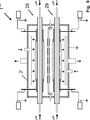
Die Plasmakammer
In dem dargestellten Ausführungsbeispiel ist die Mikrowelleneinkoppelvorrichtung
In anderen, nicht dargestellten Ausführungsbeispielen der vorliegenden Erfindung liegen die Substrate
Die Mikrowelleneinkoppelvorrichtung
Die Mikrowelleneinkoppelvorrichtung
In der in
Ferner ist um das Isolierrohr
Wie in
Die Plasmaelektroden
Im Inneren der Plasmakammer
In dem Ausführungsbeispiel von
In der Plasmakammer
In der erfindungsgemäßen Mikrowellenplasmaerzeugungsvorrichtung
In anderen, nicht gezeigten Ausführungsvarianten der vorliegenden Erfindung ist es prinzipiell auch möglich, das Mikrowellenplasma
In dem in
In dem in
In anderen, nicht dargestellten Ausführungsbeispielen ist die Plasmakammer
In dem in
Vorliegend ist der Heizer
Die Ausführungsform von
Die Winkelausrichtung der Streifenöffnung
Die Mikrowellenplasmaerzeugungsvorrichtung
In
Die Mikrowellenplasmaerzeugungsvorrichtung
Die schematisch angedeutete Gaszuführung
Das in
Auch die Ausführungsform von
Die Mikrowellenplasmaerzeugungsvorrichtung
Beispielsweise kann bei einer Siliziumnitridabscheidung durch den Gaseinlass
Die Mikrowellenplasmaerzeugungsvorrichtung
ZITATE ENTHALTEN IN DER BESCHREIBUNG QUOTES INCLUDE IN THE DESCRIPTION
Diese Liste der vom Anmelder aufgeführten Dokumente wurde automatisiert erzeugt und ist ausschließlich zur besseren Information des Lesers aufgenommen. Die Liste ist nicht Bestandteil der deutschen Patent- bzw. Gebrauchsmusteranmeldung. Das DPMA übernimmt keinerlei Haftung für etwaige Fehler oder Auslassungen.This list of the documents listed by the applicant has been generated automatically and is included solely for the better information of the reader. The list is not part of the German patent or utility model application. The DPMA assumes no liability for any errors or omissions.
Zitierte PatentliteraturCited patent literature
- DE 4136297 A1 [0002] DE 4136297 A1 [0002]
Claims (18)
Priority Applications (9)
| Application Number | Priority Date | Filing Date | Title |
|---|---|---|---|
| DE102012103425A DE102012103425A1 (en) | 2012-04-19 | 2012-04-19 | Microwave plasma generating device and method of operation thereof |
| CA2870630A CA2870630C (en) | 2012-04-19 | 2013-04-16 | Microwave plasma generating device and method for operating same |
| PCT/IB2013/053006 WO2013156924A1 (en) | 2012-04-19 | 2013-04-16 | Microwave plasma generating device and method for operating same |
| EP13726028.7A EP2839500B1 (en) | 2012-04-19 | 2013-04-16 | Microwave plasma generating device and method for operating the same |
| JP2015506336A JP6272298B2 (en) | 2012-04-19 | 2013-04-16 | Microwave plasma generator and method of operating the same |
| KR1020147031814A KR101880702B1 (en) | 2012-04-19 | 2013-04-16 | Microwave plasma generating device and method for operating same |
| CN201380032280.8A CN104380429B (en) | 2012-04-19 | 2013-04-16 | Microwave plasma generating device and method of operation thereof |
| US14/395,557 US9431217B2 (en) | 2012-04-19 | 2013-04-16 | Microwave plasma generating device and method for operating same |
| TW102114104A TWI595809B (en) | 2012-04-19 | 2013-04-18 | Micro wave plasma producing device and method for using same |
Applications Claiming Priority (1)
| Application Number | Priority Date | Filing Date | Title |
|---|---|---|---|
| DE102012103425A DE102012103425A1 (en) | 2012-04-19 | 2012-04-19 | Microwave plasma generating device and method of operation thereof |
Publications (1)
| Publication Number | Publication Date |
|---|---|
| DE102012103425A1 true DE102012103425A1 (en) | 2013-10-24 |
Family
ID=48538026
Family Applications (1)
| Application Number | Title | Priority Date | Filing Date |
|---|---|---|---|
| DE102012103425A Withdrawn DE102012103425A1 (en) | 2012-04-19 | 2012-04-19 | Microwave plasma generating device and method of operation thereof |
Country Status (9)
| Country | Link |
|---|---|
| US (1) | US9431217B2 (en) |
| EP (1) | EP2839500B1 (en) |
| JP (1) | JP6272298B2 (en) |
| KR (1) | KR101880702B1 (en) |
| CN (1) | CN104380429B (en) |
| CA (1) | CA2870630C (en) |
| DE (1) | DE102012103425A1 (en) |
| TW (1) | TWI595809B (en) |
| WO (1) | WO2013156924A1 (en) |
Cited By (3)
| Publication number | Priority date | Publication date | Assignee | Title |
|---|---|---|---|---|
| EP3309815A1 (en) | 2016-10-12 | 2018-04-18 | Meyer Burger (Germany) AG | Plasma treatment device with two microwave plasma sources coupled together and method for operating such a plasma treatment device |
| DE102018113444B3 (en) | 2018-06-06 | 2019-10-10 | Meyer Burger (Germany) Gmbh | Linear microwave plasma source with separate plasma spaces |
| DE102018113443A1 (en) * | 2018-06-06 | 2019-12-12 | Meyer Burger (Germany) Gmbh | Plasma treatment apparatus with a linear microwave plasma source and a gas guiding device |
Families Citing this family (14)
| Publication number | Priority date | Publication date | Assignee | Title |
|---|---|---|---|---|
| EP2849204B1 (en) * | 2013-09-12 | 2017-11-29 | Meyer Burger (Germany) AG | Plasma generating apparatus |
| US9240308B2 (en) * | 2014-03-06 | 2016-01-19 | Applied Materials, Inc. | Hall effect enhanced capacitively coupled plasma source, an abatement system, and vacuum processing system |
| WO2017083005A2 (en) * | 2015-09-15 | 2017-05-18 | Enig Associates, Inc. | Space plasma generator for ionospheric control |
| KR101858867B1 (en) * | 2016-12-23 | 2018-05-16 | 한국기초과학지원연구원 | Plasma processing apparatus for generating a plasma by emitting a microwave in a chamber |
| US20180308661A1 (en) | 2017-04-24 | 2018-10-25 | Applied Materials, Inc. | Plasma reactor with electrode filaments |
| US11355321B2 (en) | 2017-06-22 | 2022-06-07 | Applied Materials, Inc. | Plasma reactor with electrode assembly for moving substrate |
| US11114284B2 (en) | 2017-06-22 | 2021-09-07 | Applied Materials, Inc. | Plasma reactor with electrode array in ceiling |
| US10510515B2 (en) | 2017-06-22 | 2019-12-17 | Applied Materials, Inc. | Processing tool with electrically switched electrode assembly |
| TWI788390B (en) | 2017-08-10 | 2023-01-01 | 美商應用材料股份有限公司 | A distributed electrode array for plasma processing |
| JP6579587B2 (en) * | 2017-09-20 | 2019-09-25 | 住友理工株式会社 | Plasma processing equipment |
| US11037765B2 (en) * | 2018-07-03 | 2021-06-15 | Tokyo Electron Limited | Resonant structure for electron cyclotron resonant (ECR) plasma ionization |
| FR3091875B1 (en) * | 2019-01-17 | 2021-09-24 | Innovative Systems Et Tech Isytech | Process and treatment device for the deposition of a barrier effect coating |
| GB2590614B (en) | 2019-12-16 | 2022-09-28 | Dyson Technology Ltd | Method and apparatus for use in generating plasma |
| CN111763926A (en) * | 2020-07-02 | 2020-10-13 | 成都蓝玛尚科技有限公司 | Material synthesis system based on high-temperature normal-pressure microwave plasma |
Citations (7)
| Publication number | Priority date | Publication date | Assignee | Title |
|---|---|---|---|---|
| DE3926023A1 (en) * | 1988-09-06 | 1990-03-15 | Schott Glaswerke | CVD COATING METHOD FOR PRODUCING LAYERS AND DEVICE FOR CARRYING OUT THE METHOD |
| DE4136297A1 (en) | 1991-11-04 | 1993-05-06 | Plasma Electronic Gmbh, 7024 Filderstadt, De | Localised plasma prodn. in treatment chamber - using microwave generator connected to coupling device which passes through the wall of the chamber without using a coupling window |
| JPH08296038A (en) * | 1995-04-28 | 1996-11-12 | Nissin Electric Co Ltd | Method and device for forming film on inner peripheral surface of tubular body |
| DE19722272A1 (en) * | 1997-05-28 | 1998-12-03 | Leybold Systems Gmbh | Device for generating plasma |
| WO2003011696A1 (en) * | 2001-07-31 | 2003-02-13 | Mitsubishi Heavy Industries, Ltd. | Device for forming carbon film on inner surface of plastic vessel, and method of producing inner surface carbon film coated plastic vessel |
| DE102008018902A1 (en) * | 2008-04-14 | 2009-10-15 | Iplas Innovative Plasma Systems Gmbh | Apparatus and method for internal surface treatment of hollow bodies |
| DE102010027619B3 (en) * | 2010-07-20 | 2011-11-17 | Roth & Rau Ag | Microwave plasma source of microwave distribution system used during plasma treatment process of substrate, has inner tube and conduit that are arranged in coaxial manner, and guard portion arranged in conduit is contacted with inner tube |
Family Cites Families (24)
| Publication number | Priority date | Publication date | Assignee | Title |
|---|---|---|---|---|
| JP2965169B2 (en) * | 1990-12-07 | 1999-10-18 | 徳芳 佐藤 | Microwave discharge reaction device and electrode device |
| JPH06243993A (en) * | 1993-02-17 | 1994-09-02 | Nippon Steel Corp | Plasma focusing device |
| JP2959508B2 (en) * | 1997-02-14 | 1999-10-06 | 日新電機株式会社 | Plasma generator |
| US6103070A (en) * | 1997-05-14 | 2000-08-15 | Applied Materials, Inc. | Powered shield source for high density plasma |
| US20110121735A1 (en) * | 2000-02-22 | 2011-05-26 | Kreos Capital Iii (Uk) Limited | Tissue resurfacing |
| EP1398274A1 (en) * | 2001-06-20 | 2004-03-17 | Mitsubishi Shoji Plastics Corporation | MOISTURE AND GAS BARRIER PLASTIC CONTAINER WITH PARTITION PLATES, AND DEVICE AND METHOD FOR MANUFACTURING THE PLASTIC CONTAINER |
| DE10157601B4 (en) | 2001-11-26 | 2011-06-01 | Dieffenbacher Gmbh + Co. Kg | Device for heating pressed material in the manufacture of material plates |
| JP2004055614A (en) * | 2002-07-16 | 2004-02-19 | Tokyo Electron Ltd | Plasma processing apparatus |
| JP2005325395A (en) * | 2004-05-13 | 2005-11-24 | Utec:Kk | Plasma cvd deposition apparatus and method for producing plastic container coated with cvd film |
| US8815014B2 (en) * | 2005-11-18 | 2014-08-26 | Tokyo Electron Limited | Method and system for performing different deposition processes within a single chamber |
| DE102006048814B4 (en) * | 2006-10-16 | 2014-01-16 | Iplas Innovative Plasma Systems Gmbh | Apparatus and method for generating high plasma density microwave plasmas |
| DE102006048815B4 (en) | 2006-10-16 | 2016-03-17 | Iplas Innovative Plasma Systems Gmbh | Apparatus and method for generating high power microwave plasmas |
| US8002946B2 (en) * | 2006-10-30 | 2011-08-23 | Applied Materials, Inc. | Mask etch plasma reactor with cathode providing a uniform distribution of etch rate |
| US20100101728A1 (en) * | 2007-03-29 | 2010-04-29 | Tokyo Electron Limited | Plasma process apparatus |
| DK2253008T3 (en) | 2008-03-12 | 2017-05-08 | Alytus Corp S A | PLASMA SYSTEM |
| DE102008036766B4 (en) | 2008-08-07 | 2013-08-01 | Alexander Gschwandtner | Apparatus and method for generating dielectric layers in microwave plasma |
| TW201130007A (en) | 2009-07-09 | 2011-09-01 | Applied Materials Inc | High efficiency low energy microwave ion/electron source |
| TW201105183A (en) | 2009-07-21 | 2011-02-01 | Delta Electronics Inc | Plasma generating apparatus |
| US8415884B2 (en) * | 2009-09-08 | 2013-04-09 | Tokyo Electron Limited | Stable surface wave plasma source |
| JP2011124293A (en) * | 2009-12-09 | 2011-06-23 | Hitachi High-Technologies Corp | Plasma processing apparatus |
| US8969210B2 (en) * | 2010-09-15 | 2015-03-03 | Tokyo Electron Limited | Plasma etching apparatus, plasma etching method, and semiconductor device manufacturing method |
| JP5851899B2 (en) * | 2011-03-25 | 2016-02-03 | 東京エレクトロン株式会社 | Plasma processing equipment |
| JP5955062B2 (en) * | 2011-04-25 | 2016-07-20 | 東京エレクトロン株式会社 | Plasma processing equipment |
| US8968588B2 (en) * | 2012-03-30 | 2015-03-03 | Tokyo Electron Limited | Low electron temperature microwave surface-wave plasma (SWP) processing method and apparatus |
-
2012
- 2012-04-19 DE DE102012103425A patent/DE102012103425A1/en not_active Withdrawn
-
2013
- 2013-04-16 CN CN201380032280.8A patent/CN104380429B/en not_active Expired - Fee Related
- 2013-04-16 EP EP13726028.7A patent/EP2839500B1/en active Active
- 2013-04-16 US US14/395,557 patent/US9431217B2/en not_active Expired - Fee Related
- 2013-04-16 JP JP2015506336A patent/JP6272298B2/en not_active Expired - Fee Related
- 2013-04-16 WO PCT/IB2013/053006 patent/WO2013156924A1/en not_active Ceased
- 2013-04-16 KR KR1020147031814A patent/KR101880702B1/en not_active Expired - Fee Related
- 2013-04-16 CA CA2870630A patent/CA2870630C/en active Active
- 2013-04-18 TW TW102114104A patent/TWI595809B/en not_active IP Right Cessation
Patent Citations (7)
| Publication number | Priority date | Publication date | Assignee | Title |
|---|---|---|---|---|
| DE3926023A1 (en) * | 1988-09-06 | 1990-03-15 | Schott Glaswerke | CVD COATING METHOD FOR PRODUCING LAYERS AND DEVICE FOR CARRYING OUT THE METHOD |
| DE4136297A1 (en) | 1991-11-04 | 1993-05-06 | Plasma Electronic Gmbh, 7024 Filderstadt, De | Localised plasma prodn. in treatment chamber - using microwave generator connected to coupling device which passes through the wall of the chamber without using a coupling window |
| JPH08296038A (en) * | 1995-04-28 | 1996-11-12 | Nissin Electric Co Ltd | Method and device for forming film on inner peripheral surface of tubular body |
| DE19722272A1 (en) * | 1997-05-28 | 1998-12-03 | Leybold Systems Gmbh | Device for generating plasma |
| WO2003011696A1 (en) * | 2001-07-31 | 2003-02-13 | Mitsubishi Heavy Industries, Ltd. | Device for forming carbon film on inner surface of plastic vessel, and method of producing inner surface carbon film coated plastic vessel |
| DE102008018902A1 (en) * | 2008-04-14 | 2009-10-15 | Iplas Innovative Plasma Systems Gmbh | Apparatus and method for internal surface treatment of hollow bodies |
| DE102010027619B3 (en) * | 2010-07-20 | 2011-11-17 | Roth & Rau Ag | Microwave plasma source of microwave distribution system used during plasma treatment process of substrate, has inner tube and conduit that are arranged in coaxial manner, and guard portion arranged in conduit is contacted with inner tube |
Cited By (5)
| Publication number | Priority date | Publication date | Assignee | Title |
|---|---|---|---|---|
| EP3309815A1 (en) | 2016-10-12 | 2018-04-18 | Meyer Burger (Germany) AG | Plasma treatment device with two microwave plasma sources coupled together and method for operating such a plasma treatment device |
| WO2018069299A1 (en) | 2016-10-12 | 2018-04-19 | Meyer Burger (Germany) Ag | Plasma treatment device comprising two intercoupled microwave plasma sources and method for operating such a plasma treatment device |
| DE102018113444B3 (en) | 2018-06-06 | 2019-10-10 | Meyer Burger (Germany) Gmbh | Linear microwave plasma source with separate plasma spaces |
| WO2019233750A1 (en) * | 2018-06-06 | 2019-12-12 | Meyer Burger (Germany) Gmbh | Linear microwave plasma source having separated plasma chambers |
| DE102018113443A1 (en) * | 2018-06-06 | 2019-12-12 | Meyer Burger (Germany) Gmbh | Plasma treatment apparatus with a linear microwave plasma source and a gas guiding device |
Also Published As
| Publication number | Publication date |
|---|---|
| KR101880702B1 (en) | 2018-07-20 |
| EP2839500A1 (en) | 2015-02-25 |
| EP2839500B1 (en) | 2019-06-05 |
| US20150091442A1 (en) | 2015-04-02 |
| WO2013156924A1 (en) | 2013-10-24 |
| CN104380429A (en) | 2015-02-25 |
| CA2870630C (en) | 2018-08-28 |
| CA2870630A1 (en) | 2013-10-24 |
| KR20140145621A (en) | 2014-12-23 |
| JP6272298B2 (en) | 2018-01-31 |
| TWI595809B (en) | 2017-08-11 |
| TW201406214A (en) | 2014-02-01 |
| US9431217B2 (en) | 2016-08-30 |
| JP2015520478A (en) | 2015-07-16 |
| CN104380429B (en) | 2017-09-29 |
Similar Documents
| Publication | Publication Date | Title |
|---|---|---|
| EP2839500B1 (en) | Microwave plasma generating device and method for operating the same | |
| EP2849204B1 (en) | Plasma generating apparatus | |
| DE3708716A1 (en) | HIGH FREQUENCY ION SOURCE | |
| DE4319717A1 (en) | Device for generating planar low pressure plasma using a coil with its axis parallel to the surface of a coupling window | |
| EP0517999A1 (en) | Apparatus for reactive ion beam etching and plasma-assisted CVD processing | |
| CH696972A5 (en) | Apparatus for sputtering. | |
| EP1290926B1 (en) | High frequency plasma source | |
| DE102006037144A1 (en) | ECR plasma source | |
| DE102009044496B4 (en) | Device for generating plasma using microwaves | |
| EP2425445B1 (en) | Method for producing a plasma jet and plasma source | |
| DE4230290A1 (en) | Appts. for producing plasma using cathode sputtering - comprises plasma chamber, target connected to electrode, magnetron, and microwave emitter | |
| DE102013107659B4 (en) | Plasma-chemical coating device | |
| EP0568049B1 (en) | Apparatus and method for coating the inside of a hollow object by microwave-assisted plasma CVD | |
| DE102004043967B4 (en) | Arrangement and method for plasma treatment of a substrate | |
| DE10008482A1 (en) | High frequency plasma source with support for field coil, gas distribution and plasma jet extraction, has additional high frequency matching network | |
| DE102012111186B4 (en) | Method and apparatus for generating a magnetron discharge | |
| DE10320805A1 (en) | Device for processing cylindrical substrates, such as wires and cables, comprises a process chamber, and a dielectric barrier arranged between an electrode and a lead functioning as the counter electrode | |
| EP1401249A2 (en) | Plasma source | |
| DE102005049266B4 (en) | Apparatus and method for the plasma treatment of objects | |
| WO1992006224A1 (en) | Component-coating process and device | |
| DE69635035T2 (en) | Method and device for coating or cleaning a substrate | |
| WO2010049158A2 (en) | Vhf assembly | |
| DE10247888A1 (en) | Device for generating plasmas by high-frequency discharges | |
| DE102024102647A1 (en) | Dual plasma applicator for a plasma generator, plasma generator, plasma processing system, and method for igniting a plasma | |
| CH633729A5 (en) | Device for coating products |
Legal Events
| Date | Code | Title | Description |
|---|---|---|---|
| R163 | Identified publications notified | ||
| R081 | Change of applicant/patentee |
Owner name: MEYER BURGER (GERMANY) AG, DE Free format text: FORMER OWNER: ROTH & RAU AG, 09337 HOHENSTEIN-ERNSTTHAL, DE |
|
| R082 | Change of representative |
Representative=s name: STEINIGER, CARMEN, DIPL.-ING. DR.-ING., DE |
|
| R005 | Application deemed withdrawn due to failure to request examination |