DE102012101939A1 - Method and device for the layered construction of a shaped body - Google Patents
Method and device for the layered construction of a shaped body Download PDFInfo
- Publication number
- DE102012101939A1 DE102012101939A1 DE102012101939A DE102012101939A DE102012101939A1 DE 102012101939 A1 DE102012101939 A1 DE 102012101939A1 DE 102012101939 A DE102012101939 A DE 102012101939A DE 102012101939 A DE102012101939 A DE 102012101939A DE 102012101939 A1 DE102012101939 A1 DE 102012101939A1
- Authority
- DE
- Germany
- Prior art keywords
- nozzle
- shaped body
- layer
- container
- strand
- Prior art date
- Legal status (The legal status is an assumption and is not a legal conclusion. Google has not performed a legal analysis and makes no representation as to the accuracy of the status listed.)
- Withdrawn
Links
Images


Classifications
-
- B—PERFORMING OPERATIONS; TRANSPORTING
- B29—WORKING OF PLASTICS; WORKING OF SUBSTANCES IN A PLASTIC STATE IN GENERAL
- B29C—SHAPING OR JOINING OF PLASTICS; SHAPING OF MATERIAL IN A PLASTIC STATE, NOT OTHERWISE PROVIDED FOR; AFTER-TREATMENT OF THE SHAPED PRODUCTS, e.g. REPAIRING
- B29C64/00—Additive manufacturing, i.e. manufacturing of three-dimensional [3D] objects by additive deposition, additive agglomeration or additive layering, e.g. by 3D printing, stereolithography or selective laser sintering
- B29C64/10—Processes of additive manufacturing
- B29C64/106—Processes of additive manufacturing using only liquids or viscous materials, e.g. depositing a continuous bead of viscous material
- B29C64/112—Processes of additive manufacturing using only liquids or viscous materials, e.g. depositing a continuous bead of viscous material using individual droplets, e.g. from jetting heads
-
- B—PERFORMING OPERATIONS; TRANSPORTING
- B29—WORKING OF PLASTICS; WORKING OF SUBSTANCES IN A PLASTIC STATE IN GENERAL
- B29C—SHAPING OR JOINING OF PLASTICS; SHAPING OF MATERIAL IN A PLASTIC STATE, NOT OTHERWISE PROVIDED FOR; AFTER-TREATMENT OF THE SHAPED PRODUCTS, e.g. REPAIRING
- B29C64/00—Additive manufacturing, i.e. manufacturing of three-dimensional [3D] objects by additive deposition, additive agglomeration or additive layering, e.g. by 3D printing, stereolithography or selective laser sintering
- B29C64/10—Processes of additive manufacturing
- B29C64/165—Processes of additive manufacturing using a combination of solid and fluid materials, e.g. a powder selectively bound by a liquid binder, catalyst, inhibitor or energy absorber
-
- B—PERFORMING OPERATIONS; TRANSPORTING
- B29—WORKING OF PLASTICS; WORKING OF SUBSTANCES IN A PLASTIC STATE IN GENERAL
- B29C—SHAPING OR JOINING OF PLASTICS; SHAPING OF MATERIAL IN A PLASTIC STATE, NOT OTHERWISE PROVIDED FOR; AFTER-TREATMENT OF THE SHAPED PRODUCTS, e.g. REPAIRING
- B29C64/00—Additive manufacturing, i.e. manufacturing of three-dimensional [3D] objects by additive deposition, additive agglomeration or additive layering, e.g. by 3D printing, stereolithography or selective laser sintering
- B29C64/40—Structures for supporting 3D objects during manufacture and intended to be sacrificed after completion thereof
-
- B—PERFORMING OPERATIONS; TRANSPORTING
- B29—WORKING OF PLASTICS; WORKING OF SUBSTANCES IN A PLASTIC STATE IN GENERAL
- B29C—SHAPING OR JOINING OF PLASTICS; SHAPING OF MATERIAL IN A PLASTIC STATE, NOT OTHERWISE PROVIDED FOR; AFTER-TREATMENT OF THE SHAPED PRODUCTS, e.g. REPAIRING
- B29C64/00—Additive manufacturing, i.e. manufacturing of three-dimensional [3D] objects by additive deposition, additive agglomeration or additive layering, e.g. by 3D printing, stereolithography or selective laser sintering
- B29C64/10—Processes of additive manufacturing
- B29C64/106—Processes of additive manufacturing using only liquids or viscous materials, e.g. depositing a continuous bead of viscous material
- B29C64/124—Processes of additive manufacturing using only liquids or viscous materials, e.g. depositing a continuous bead of viscous material using layers of liquid which are selectively solidified
- B29C64/129—Processes of additive manufacturing using only liquids or viscous materials, e.g. depositing a continuous bead of viscous material using layers of liquid which are selectively solidified characterised by the energy source therefor, e.g. by global irradiation combined with a mask
- B29C64/135—Processes of additive manufacturing using only liquids or viscous materials, e.g. depositing a continuous bead of viscous material using layers of liquid which are selectively solidified characterised by the energy source therefor, e.g. by global irradiation combined with a mask the energy source being concentrated, e.g. scanning lasers or focused light sources
-
- B—PERFORMING OPERATIONS; TRANSPORTING
- B29—WORKING OF PLASTICS; WORKING OF SUBSTANCES IN A PLASTIC STATE IN GENERAL
- B29K—INDEXING SCHEME ASSOCIATED WITH SUBCLASSES B29B, B29C OR B29D, RELATING TO MOULDING MATERIALS OR TO MATERIALS FOR MOULDS, REINFORCEMENTS, FILLERS OR PREFORMED PARTS, e.g. INSERTS
- B29K2995/00—Properties of moulding materials, reinforcements, fillers, preformed parts or moulds
- B29K2995/0018—Properties of moulding materials, reinforcements, fillers, preformed parts or moulds having particular optical properties, e.g. fluorescent or phosphorescent
- B29K2995/002—Coloured
- B29K2995/0021—Multi-coloured
-
- B—PERFORMING OPERATIONS; TRANSPORTING
- B33—ADDITIVE MANUFACTURING TECHNOLOGY
- B33Y—ADDITIVE MANUFACTURING, i.e. MANUFACTURING OF THREE-DIMENSIONAL [3-D] OBJECTS BY ADDITIVE DEPOSITION, ADDITIVE AGGLOMERATION OR ADDITIVE LAYERING, e.g. BY 3-D PRINTING, STEREOLITHOGRAPHY OR SELECTIVE LASER SINTERING
- B33Y10/00—Processes of additive manufacturing
-
- B—PERFORMING OPERATIONS; TRANSPORTING
- B33—ADDITIVE MANUFACTURING TECHNOLOGY
- B33Y—ADDITIVE MANUFACTURING, i.e. MANUFACTURING OF THREE-DIMENSIONAL [3-D] OBJECTS BY ADDITIVE DEPOSITION, ADDITIVE AGGLOMERATION OR ADDITIVE LAYERING, e.g. BY 3-D PRINTING, STEREOLITHOGRAPHY OR SELECTIVE LASER SINTERING
- B33Y30/00—Apparatus for additive manufacturing; Details thereof or accessories therefor
-
- B—PERFORMING OPERATIONS; TRANSPORTING
- B33—ADDITIVE MANUFACTURING TECHNOLOGY
- B33Y—ADDITIVE MANUFACTURING, i.e. MANUFACTURING OF THREE-DIMENSIONAL [3-D] OBJECTS BY ADDITIVE DEPOSITION, ADDITIVE AGGLOMERATION OR ADDITIVE LAYERING, e.g. BY 3-D PRINTING, STEREOLITHOGRAPHY OR SELECTIVE LASER SINTERING
- B33Y40/00—Auxiliary operations or equipment, e.g. for material handling
Landscapes
- Chemical & Material Sciences (AREA)
- Engineering & Computer Science (AREA)
- Materials Engineering (AREA)
- Physics & Mathematics (AREA)
- Manufacturing & Machinery (AREA)
- Mechanical Engineering (AREA)
- Optics & Photonics (AREA)
Abstract
Da bei Anwendung des Prototyping-Verfahrens auf Betonwerkstoffe das Aushärten nicht so schnell geht, dass beim Aufbringen der nächsten Schicht (2b) die darunter liegende Schicht (2a) bereits vollständig ausgehärtet ist, wird zum Ausgleich der fehlenden Druckbelastbarkeit der darunter liegenden Schicht (2a) um den entstehenden Formkörper (100) herum ein Stützmaterial (4) vorgesehen, welches vorzugsweise die gleiche spezifische Dichte wie das Material (3) des Formkörpers (100) besitzt. Dann ist sowohl ein 3D-Printing als auch ein selektives Aushärten als Aufbauverfahren machbar.Since, when the prototyping method is applied to concrete materials, curing does not take place so rapidly that the underlying layer (2a) is already fully cured when the next layer (2b) is applied, the lack of compressive strength of the underlying layer (2a) is compensated. around the resulting molded body (100) around a support material (4) provided, which preferably has the same specific gravity as the material (3) of the shaped body (100). Then both a 3D printing and a selective curing as a construction method is feasible.
Description
I. AnwendungsgebietI. Field of application
Die Erfindung betrifft ein Verfahren zum schichtweisen Aufbau eines Formkörpers aus aushärtendem Material, sowie eine Vorrichtung, die hierfür geeignet ist.The invention relates to a method for the layered structure of a shaped body made of hardening material, as well as a device which is suitable for this purpose.
II. Technischer HintergrundII. Technical background
Wenn in der Vergangenheit ein Formkörper aus einem aushärtenden Material hergestellt werden sollte, so war hierfür zunächst die Herstellung einer entsprechenden Negativ-Form notwendig, in die das meist flüssige Ausgangs-Material eingebracht wurde und in der es aushärten konnte.In the past, when a molded article was to be made of a thermosetting material, it was first necessary to produce a corresponding negative mold into which the mostly liquid starting material was introduced and in which it could cure.
Der Aufwand der Herstellung einer Negativform lohnt sich jedoch erst, wenn diese Negativform mehrfach, am besten sehr häufig, wieder verwendet wird. Dementsprechend teuer war die Herstellung von solchen Formkörpern, die in kleiner Stückzahl oder gar als Einzelanfertigung hergestellt werden sollten, da ein anderes Herstellungsverfahren nicht möglich war.However, the expense of producing a negative mold pays off only if this negative mold is reused several times, preferably very frequently. Accordingly expensive was the production of such moldings, which should be produced in small quantities or even as one-off production, since a different manufacturing process was not possible.
Seit einigen Jahren ist jedoch durch das so genannte Prototyping die Herstellung ohne Negativform möglich, allerdings nur aus bestimmten Kunststoffen als Ausgangsmaterial und nur mit begrenzten Abmessungen bis beispielsweise 1 m3. Dabei sind zwei Verfahren zu unterscheiden, die beide in einem an die Form des herzustellenden Formkörpers nicht angepassten, meist kubusförmigen, Behälter ablaufen:
Beim so genannten 3D-Printing wird mittels einer gesteuerten Düse, ähnlich wie bei einem Tintenstrahldrucker, auf der Bodenfläche des Behälters eine erste Schicht aus dem Körpermaterial aufgebracht im Bereich der Kontur des herzustellenden Formkörpers auf dieser Höhe. Das Körpermaterial ist sehr schnell aushärtend, so dass unmittelbar anschließend die nächste Schicht darüber aufgebracht werden kann und so fort, wobei sich die Querschnitte der Schichten jeweils geringfügig ändern um die gewünschte, sich in der Höhe ändernde, Kontur des Formkörpers zu erzielen.For some years, however, by the so-called prototyping, the production without negative mold possible, but only from certain plastics as starting material and only with limited dimensions up to 1 m 3, for example. In this case, two methods are to be distinguished, both of which take place in a container which is not adapted to the shape of the shaped article to be produced, usually a cube-shaped container.
In so-called 3D printing, a first layer of the body material is applied by means of a controlled nozzle, similar to an ink jet printer, on the bottom surface of the container in the region of the contour of the shaped body to be produced at this height. The body material hardens very rapidly, so that immediately thereafter the next layer can be applied over it, and so on, with the cross sections of the layers each slightly changing to achieve the desired height-varying contour of the shaped body.
Beim so genannten selektiven Aushärten besteht dagegen das Körpermaterial aus einem Material, welches zum Beispiel durch Wärme oder ein aufgebrachtes Bindemittel sehr schnell aushärtet. Dieses Körpermaterial wird zunächst in einer ersten Schicht über die gesamte Bodenfläche des Behälters aufgebracht. Anschließend wird nur in dem Bereich, der den Formkörper umfassen soll, diese pulverförmige Schicht aus Körpermaterial ausgehärtet, zum Beispiel mit einem darauf fokussierten Laserstrahl oder einer anderen eng begrenzten Wärmequelle so stark erhitzt, dass das pulverförmige Füllmaterial in diesen Bereichen sofort aushärtet. Anschließend wird eine weitere Schicht des pulverförmigen Materials über die gesamte Fläche des Behälters gelegt und entsprechend verfahren. Nach Fertigstellung des Formkörpers wird dieser aus dem Behälter entnommen und das umgebende, nicht ausgehärtete Umgebungsmaterial wird durch Abklopfen oder Abbürsten vom Formkörper entfernt.In the case of the so-called selective curing, by contrast, the body material consists of a material which hardens very quickly, for example, by heat or an applied binder. This body material is first applied in a first layer over the entire bottom surface of the container. Subsequently, only in the region which is to comprise the shaped body, this pulverulent layer of body material is cured, for example heated with a laser beam focused thereon or another narrowly limited heat source, so that the pulverulent filling material immediately cures in these areas. Subsequently, another layer of the powdery material is placed over the entire surface of the container and proceed accordingly. After completion of the molding this is removed from the container and the surrounding, uncured ambient material is removed by tapping or brushing from the molding.
Bei beiden Verfahren liegt in der Regel die Schichtdicke im Bereich von deutlich unter 1 mm, beim erstgenannten Verfahren in der Regel bei einem 1/10 mm. Dementsprechend werden für den Aufbau eines Formkörpers, der beispielsweise eine Höhe von 50 cm besitzt, teilweise mehr als 10 h benötigt. Darüber hinaus sind die hierfür geeigneten Materialien teuer, so dass sie für die Herstellung großvolumiger Bauteile, die insbesondere keine allzu hohen Kosten verursachen dürfen, nicht infrage kommen.In both methods, the layer thickness is generally in the range of well below 1 mm, in the former method usually at a 1/10 mm. Accordingly, for the construction of a molded article having, for example, a height of 50 cm, sometimes more than 10 hours are needed. In addition, the materials suitable for this purpose are expensive, so they are not eligible for the production of large-volume components, which in particular may not cause too high a cost.
Es gibt jedoch eine ganze Reihe von Formkörpern, die zu einem geringen Preis und mit einem großen Volumen hergestellt werden müssen, und für die deshalb diese Verfahren bisher nicht infrage kamen, beispielsweise Fertigbauteile aus Beton, Gussformen für den Metallguss, faserverstärkte Kunststoffteile für den sonder-Fahrzeugbau, insbesondere Bootsbau oder Karosseriebau von Personenkraftwagen sowie viele weitere Anwendungen.However, there is a whole range of moldings which have to be produced at a low price and with a large volume, and for which therefore these methods have hitherto been out of the question, for example prefabricated components made of concrete, casting molds for metal casting, fiber-reinforced plastic parts for the special purpose. Vehicle construction, in particular boatbuilding or body construction of passenger cars as well as many other applications.
III. Darstellung der ErfindungIII. Presentation of the invention
a) Technische Aufgabea) Technical task
Es ist daher die Aufgabe gemäß der Erfindung, ein gattungsgemäßes Verfahren sowie eine dafür geeignete Vorrichtung zur Verfügung zu stellen, die auch für die Herstellung von großvolumigen und niederpreisigen Bauteilen geeignet sind.It is therefore the object of the invention to provide a generic method and a device suitable for this purpose, which are also suitable for the production of large-volume and low-priced components.
b) Lösung der Aufgabeb) Solution of the task
Diese Aufgabe wird durch die Merkmale der Ansprüche 1 und 14 gelöst. Vorteilhafte Ausführungsformen ergeben sich aus den Unteransprüchen.This object is solved by the features of
Durch das Aufbringen der nächsten Schicht, bevor die eine Schicht darunter oder gar noch mehrere Schichten darunter ausgehärtet ist, insbesondere vollständig ausgehärtet ist, wird das Verfahren auf eine Vielzahl von Bindungsarten und Bindern erweitert, die relativ langsam abbinden im Vergleich zu den bisher üblichen speziellen Kunststoffen und deren Art der Bindung.By applying the next layer before the one layer below or even several layers below it is cured, in particular fully cured, the method is extended to a variety of types of bonds and binders that set relatively slowly compared to the hitherto customary special plastics and their kind of binding.
Hier können beispielsweise als Füllmaterial die gleichen Füllmaterialien wie bei Beton, also Sand, Kies oder ein Gemenge aus beiden, verwendet werden, während als Binder nicht nur Zement – vor allem in flüssiger oder pastöser Form als Zementschlämme oder Zementpaste – und darüber hinaus die gesamte Palette der im Betonbau verwendeten schneller abbindenden Binder, zum Beispiel Gips oder Binder auf Zementbasis oder auf Kunststoffbasis zum Einsatz kommt.Here, for example, can be used as filler the same filling materials as in concrete, ie sand, gravel or a mixture of both, while as a binder not only cement - especially in liquid or pasty form as cement slurry or cement paste - and, moreover, the entire range of faster setting binder used in concrete construction, for example gypsum or cement-based or plastic-based binder is used.
Auch Holzleim und andere Binder auf natürlicher Basis stehen – je nach Anwendungszweck des herzustellenden Formkörpers – zur Verfügung. Ebenso ist Holzmehl ein unter Umständen geeignetes Füllmaterial. Damit stehen sowohl von Seiten des Füllmaterials als auch von Seiten des Binders sehr kostengünstige und in großer Menge verfügbare Materialien zur Verfügung.Wood glue and other binders on a natural basis are also available, depending on the intended use of the shaped article to be produced. Likewise, wood flour is a possibly suitable filler. Thus, both from the side of the filler and the sides of the binder very inexpensive and available in large quantities available materials.
Der Nachteil ist, dass Zusatzmaßnahmen getroffen werden müssen, um die tiefer liegende, noch nicht ausgehärtete Schicht mit einer neu aufgebrachten Schicht belasten zu können, da sie ja in der Regel hierfür selbst noch nicht ausreichend druckstabil ist.The disadvantage is that additional measures must be taken in order to be able to load the deeper, not yet hardened layer with a newly applied layer, since, as a rule, it is not yet sufficiently pressure-stable for this itself.
Eine erste, in der Praxis jedoch kaum realisierbare, Möglichkeit besteht darin, dass die darunter liegende Schicht noch nicht vollständig ausgehärtet aber dennoch bereits so druckstabil ist, dass die nächste Schicht darüber bereits aufgebracht werden kann.A first, but in practice hardly feasible, possibility is that the underlying layer is not fully cured yet but already so pressure-stable that the next layer can already be applied over it.
Sofern dies jedoch nicht der Fall ist, kommt als zweite Möglichkeit in Betracht, an den Begrenzungsflächen des Formkörpers während dessen Aufbau, also dessen Aushärtezeit, ein Stützmaterial anliegen zu lassen, welches beispielsweise ein unerwünschtes Verformen der noch nicht ausgehärteten Schichten in die Breite verhindert.If this is not the case, however, comes as a second possibility to rest on the boundary surfaces of the molding during its construction, ie its curing time, a support material which prevents, for example, an undesirable deformation of the uncured layers in the width.
Hierbei muss wiederum nach dem Herstellungsverfahren unterschieden werden:
Beim 3D-Printing wird mittels einer Düse das Körpermaterial, aus dem der Formkörper hergestellt wird, Schicht für Schicht und ausschließlich im Bereich des Formkörpers aufgetragen und dadurch der Formkörper hoch gezogen.Here again, a distinction must be made according to the manufacturing process:
In the case of 3D printing, the body material from which the shaped body is produced is applied layer by layer and exclusively in the area of the shaped body by means of a nozzle, thereby pulling the shaped body upwards.
Für die Zwecke der vorliegenden Anmeldung soll klargestellt werden, dass trotz der Verwendung des Begriffes „Düse” hiermit jede Art von Auslassöffnung gemeint ist, auch wenn sie nicht die düsentypische Verengung aufweist.For the purposes of the present application, it is to be understood that despite the use of the term "nozzle", it is meant any type of outlet orifice even though it does not have the nozzle-typical restriction.
Bei diesem Verfahren wird also mittels einer oder mehrerer Düsen jeweils ein Strang eines Materials neben dem anderen ausgebracht, wobei die Stränge des noch nicht ausgehärteten Materiales sich kontaktieren und teilweise durchmischen und im ausgehärteten Zustand daher eine Struktur ergeben, in der die ursprünglich einzelnen aufgebrachten Stränge nicht mehr zu erkennen sind.In this method, one strand of a material is thus applied in addition to the other by means of one or more nozzles, wherein the strands of the uncured material contact and partially mixed and therefore result in the cured state, a structure in which the originally individual applied strands not More can be seen.
Das Problem stellen hierbei die Bereiche der frisch aufgebrachten Schicht nahe der Begrenzungsflächen des Formkörpers dar, in der Regel der äußeren Begrenzungsflächen, aber wenn der Formkörper innere Hohlräume aufweist, auch der inneren Begrenzungsflächen:
Sofern das aufgebrachte Körpermaterial ausreichend weich und pastös ist, wird es sich ohne weitere Zusatzmaßnahmen in die Breite ausdehnen, vor allem wenn die nächste aufgebrachte Schicht darauf zu lasten beginnt.The problem here is the areas of the freshly applied layer near the boundary surfaces of the shaped body, usually the outer boundary surfaces, but if the shaped body has internal cavities, also the inner boundary surfaces:
If the applied body material is sufficiently soft and pasty, it will expand without further additional measures, especially when the next applied layer begins to load on it.
Erfindungsgemäß wird dem entgegen getreten, indem auf der Außenseite der Begrenzungsflächen Stützmaterial angeordnet wird, welches zusammen mit dem Formkörper hochgezogen wird.According to the invention is counteracted by supporting material is arranged on the outside of the boundary surfaces, which is pulled up together with the molding.
In einer bevorzugten Ausführung wird mittels einer Düse ein Strang aus Körpermaterial entlang des Randes der aktuellen Schicht des aufzubauenden Formkörpers gelegt und gleichzeitig oder nur mit geringer zeitlicher Verzögerung auf der Außenseite der Begrenzungsfläche ein Strang aus Stützmaterial.In a preferred embodiment, a strand of body material is placed along the edge of the current layer of the molded body to be constructed by means of a nozzle and at the same time or only with a slight delay on the outside of the boundary surface, a strand of support material.
Da das Ziel bei der Herstellung eines Formkörpers in der Regel darin besteht, eine möglichst maßhaltige Gestalt zu erzeugen und darüber hinaus meist auch eine glatte, absatzfreie Oberfläche, werden erfindungsgemäß die beiden Stränge aus Körpermaterial und Stützmaterial in Verlaufsrichtung vorzugsweise direkt nebeneinander ausgebracht zum Beispiel mit schräg gegeneinander gerichteten Düsen, sodass die beiden Stränge mit dem Ausbringungsdruck gegeneinander gedrückt werden und dadurch eine anschließende weitere Verformung der Außenseite des Stranges aus Körpermaterial nicht mehr eintreten kann.Since the goal in the production of a molded body is usually to produce a dimensionally stable as possible and beyond usually a smooth, paragraph free surface, the two strands of body material and support material in the direction preferably applied directly adjacent to each other, for example, with an angle oppositely directed nozzles, so that the two strands are pressed against each other with the application pressure and thus a subsequent further deformation of the outside of the strand of body material can no longer occur.
Zu diesem Zweck sollte das Stützmaterial ein spezifisches Gewicht und/oder eine Körnung aufweisen, die etwa dem des Körpermaterials entspricht, oder die Körnung des Stützmaterials kleiner ist als die des Körpermaterials.For this purpose, the support material should have a specific weight and / or a grain size which corresponds approximately to that of the body material, or the grain size of the support material is smaller than that of the body material.
Abseits der Begrenzungsflächen kann sowohl der Formkörper einerseits als auch das Stützmaterial andererseits entweder mit gleichartigen Düsen oder mit Düsen größeren Querschnitts, insbesondere größerer Breite, ausgebracht werden, um das Füllen in der Fläche schneller zu erledigen.Away from the boundary surfaces, both the shaped body on the one hand and the support material on the other hand, either with similar nozzles or nozzles larger cross-section, in particular larger width, are applied to make filling in the area faster.
Das Stützmaterial kann dabei ein nur geringfügig oder auch überhaupt nicht aushärtendes Material sein, bevorzugt wird es jedoch feucht ausgebracht. Falls es aushärtet, sollte entweder der Aushärtevorgang des Stützmaterials vorzugsweise schneller erfolgen als der des Körpermaterials oder umgekehrt.The support material can be a material that does not harden at all or even at all, but it is preferably applied moist. If it hardens, either the curing process of the support material should preferably be faster than that of the body material or vice versa.
Der herzustellende Körper kann im Übrigen in seinem Inneren aus unterschiedlichen Materialien bestehen, und die unterschiedlichen Körpermaterialien werden von separaten Düsen innerhalb der einzelnen Schichten eingebracht. Auf diese Art und Weise können beispielsweise Körper erzeugt werden, die aus einem sehr harten und stabilen dünnwandigen Außenmaterial und einem weniger stabilen, beispielsweise isolierenden Innenmaterial bestehen oder auch im Inneren Hohlräume aufweisen, die für die Verwendung des Bauteils von Bedeutung sind, beispielsweise für Installationen, als Wärmetauscher oder ähnliches. Incidentally, the body to be manufactured may be made of different materials in its interior, and the different body materials are introduced from separate nozzles within the individual layers. In this way, for example, bodies can be produced which consist of a very hard and stable thin-walled outer material and a less stable, for example insulating, inner material or also have cavities inside, which are important for the use of the component, for example for installations, as a heat exchanger or the like.
Auch kann beispielsweise das Körpermaterial von Innen nach Außen auch in seiner Körnigkeit variieren, indem beispielsweise nahe der Begrenzungsflächen ein sehr feinkörniges Material verwendet wird, um eine glatte, feinporige Begrenzungsfläche zu erzeugen, während weiter im Inneren des Formkörpers grobkörniges Füllmaterial, beispielsweise in Form von grobkörnigen Zuschlagsstoffen wie etwa Kies, verwendet werden können.Also, for example, the body material from inside to outside in its graininess vary by, for example, near the boundary surfaces, a very fine-grained material is used to produce a smooth, fine-pored boundary surface, while further inside the molding coarse-grained filler, for example in the form of coarse grained Aggregates such as gravel, can be used.
Um eine glatte absatzlose Begrenzungsfläche des späteren Formkörpers zu erzeugen, an der die einzelnen aufgebrachten Schichten nicht mehr sichtbar sind, können weitere Zusatzmaßnahmen durchgeführt werden:
Beispielsweise kann direkt aus der Düse oder auch separat auf die Begrenzungsfläche der frisch aufgebrachten Schicht des Formkörpers ein Glättungsmittel, ein Schnellbinder o. ä. aufgebracht werden, oder die Aushärtung der Außenfläche des äußersten Stranges wird beschleunigt durch Aufbringen von Wärme, beispielsweise in Form von heißer Luft, oder in Form von elektromagnetischer Strahlung, beispielsweise von UV-Strahlung, indem das Körpermaterial und/oder das Stützmaterial, zumindest nahe der Begrenzungsflächen, ein Material enthält, welches auf diese Art und Weise sehr schnell ausgehärtet werden kann.In order to produce a smooth, uncut boundary surface of the subsequent shaped body, at which the individual applied layers are no longer visible, further additional measures can be carried out:
For example, directly from the nozzle or separately on the boundary surface of the freshly applied layer of the molding a smoothing agent, a quick binder o. Ä. Are applied, or the curing of the outer surface of the outermost strand is accelerated by applying heat, for example in the form of hotter Air, or in the form of electromagnetic radiation, such as UV radiation, by the body material and / or the support material, at least near the boundary surfaces, containing a material which can be cured very quickly in this way.
Ebenso wie ein entsprechender Schnellbinder oder ein Glättungsmittel direkt beim Ausbringen mittels der Düse für das Körpermaterial, beispielsweise in speziellen Zusatzauslässen auf der Außenseite der Düse, also an den Begrenzungsflächen des Formkörpers, erfolgen kann, können über solche Zusatzauslässe in der Düse auch spezielle Komponenten dem Körpermaterial zugemischt werden, welche erst ein schnelles Aushärten durch Wärme oder z. B. UV-Licht oder andere physikalische oder chemische Umgebungsbedingungen ermöglichen, die dann vorzugsweise jedoch zur Einwirkung gebracht werden sollen, bevor die entsprechende Außenseite der neuen Schicht durch das Stützmaterial abgedeckt wird.Just as a corresponding rapid binder or a smoothing agent can be carried out directly during application by means of the nozzle for the body material, for example in special Zusatzauslässen on the outside of the nozzle, ie at the boundary surfaces of the shaped body, such special outlets in the nozzle and special components of the body material are admixed, which only a rapid curing by heat or z. As UV light or other physical or chemical environmental conditions allow, but then preferably be brought to act before the corresponding outer side of the new layer is covered by the support material.
Um eine noch bessere Oberfläche zu erzielen und insbesondere ein Anhaften oder Einsickern von Bestandteilen des Körpermaterials in das Stützmaterial oder umgekehrt zu vermeiden, kann an die Begrenzungsflächen bei jeder Schicht zwischen Stützmaterial und Körpermaterial eine Trennschicht aus einem Trennmittel eingebracht werden, welches vorzugsweise wiederum mittels einer separaten, senkrecht stehenden Düse ausgebracht wird. Das Trennmittel wird dabei nur noch so gering wie notwendig pastös sein und insbesondere nicht aushärtend oder kaum aushärtend, denn es soll vor allem sofort nach dem Ausbringen eine seitliche Barriere für den äußersten Strang aus Körpermaterial bilden. Als Trennmittel können auch sehr kostengünstige Materialien wie Lehm, Ton, Wachs o. ä. verwendet werden, die später auch wiederverwendbar sein können.In order to achieve an even better surface and in particular to avoid sticking or infiltration of constituents of the body material into the support material or vice versa, a separating layer of a release agent can be applied to the boundary surfaces in each layer between support material and body material, which in turn preferably by means of a separate , vertical nozzle is discharged. The release agent will be pasty as little as necessary and in particular not hardening or hardly curing, because it should form a lateral barrier for the outermost strand of body material, especially immediately after deployment. As a release agent and very inexpensive materials such as clay, clay, wax o. Ä. Be used, which can be reused later.
Je nach Geschwindigkeit der Aushärtung vor allem der Außenseite des Körpermaterials kann auch das Entlangführen einer Trennklinge an der Begrenzungsfläche, also zwischen Körpermaterial und Stützmaterial, ausreichend sein. Die Trennklinge kann aus einem festen z. B. Blech oder einem flexiblen Materialstreifen wie etwa einem Stück Folie, bestehen und direkt an der Düse befestigt sein. Dadurch wird auch eine mechanisch glättende Wirkung der Außenfläche des Körpermaterials erreicht.Depending on the speed of curing especially the outside of the body material and the passing of a separating blade on the boundary surface, so between body material and support material may be sufficient. The separating blade can be made of a solid z. As sheet metal or a flexible strip of material such as a piece of foil, and be attached directly to the nozzle. As a result, a mechanical smoothing effect of the outer surface of the body material is achieved.
Da in dem erfindungsgemäßen Verfahren vorgesehen ist, auch große Formkörper mit Abmessungen von zum Teil mehreren Metern herzustellen, wird das Material in Schichtdicken von meist mehr als einem Millimeter, besser mehr als zwei Millimetern, besser mehr als fünf Millimetern, ausgebracht, um einen schnellen Aufbau zu ermöglichen.Since it is provided in the method according to the invention to produce large moldings with dimensions of sometimes several meters, the material in layer thicknesses of usually more than one millimeter, more preferably more than two millimeters, more preferably more than five millimeters, applied to a quick set up to enable.
Da die Außenwand des Formkörpers nicht immer genau lotrecht zur Schichtebene steht, sind die Düsen, die vor allem den äußersten Strang und damit die Begrenzungsfläche des Formkörpers erzeugen, vorzugsweise um ihre Längsachse schwenkbar in Anpassung an die momentane Orientierung des Formkörpers bei der herzustellenden Schicht. Die Düse besitzt dann vorzugsweise zumindest eine ebene Seitenfläche, bevorzugt besitzt die Düse einen rechteckigen Querschnitt, und kann somit mit einer ihrer Seitenflächen parallel zur Lage der Begrenzungsfläche bei dieser Schicht eingestellt werden.Since the outer wall of the shaped body is not always exactly perpendicular to the layer plane, the nozzles, which produce especially the outermost strand and thus the boundary surface of the shaped body, preferably about its longitudinal axis pivotally in adaptation to the instantaneous orientation of the shaped body in the layer to be produced. The nozzle then preferably has at least one flat side surface, preferably the nozzle has a rectangular cross section, and thus can be adjusted with one of its side surfaces parallel to the position of the boundary surface in this layer.
Ein anderes Verfahren besteht in der selektiven Aushärtung einer durchgehenden Schicht aus Material:
Dabei besteht das Körpermaterial aus mindestens zwei Komponenten, nämlich einmal einem Füllmaterial wie etwa Sand, Holzmehl, Kies oder ähnlichem und einem Binder, beispielsweise Zementschlämme. Dabei wird Schicht für Schicht über den gesamten Behälter, in dem der Formkörper entsteht, zunächst eine Schicht aus dem Füllmaterial aufgebracht und dann nur in den Bereichen des herzustellenden Formkörpers ein Binder, meist in flüssiger Form, auf der Schicht aus Füllmaterial ausgebracht, welches das Füllmaterial durchdringt und damit tränkt und eine aushärtbare Mischung ergibt.Another method is selective hardening of a continuous layer of material:
In this case, the body material consists of at least two components, namely once a filler such as sand, wood flour, gravel or the like and a binder, such as cement slurry. Here, layer by layer over the entire container in which the shaped body is formed, first a layer of the filler is applied and then only in the areas of the shaped body to be produced a binder, usually in liquid Form, applied to the layer of filler material, which penetrates the filler material and soaks and gives a curable mixture.
Um hier eine saubere Begrenzungsfläche des Formkörpers herzustellen, kann vor oder während des Aufbringens des Binders im Randbereich des Formkörpers entweder die beschriebene Trennschicht aus einem Trennmittel an der Grenze zwischen Formkörper und umgebendem Stützmaterial eingebracht werden, oder die beschriebene Trennklinge an dieser Grenze entlang geführt werden, unter Umständen auch beides in Kombination.In order to produce a clean boundary surface of the molded body here, before or during the application of the binder in the edge region of the molded body, either the separating layer described can be introduced from a release agent at the boundary between the molded body and the surrounding support material, or the separating blade described can be guided along this boundary, possibly both in combination.
Eine solche Trennklinge kann auch beheizt sein und durch ihre Wärme das daran entlang gleitende Körpermaterial aushärten oder die Trennklinge kann Auslassöffnungen für Chemikalien oder zur Erzeugung eines bestimmten physikalischen Zustandes in seiner Umgebung aufweisen, beispielsweise UV-Licht abgeben, um einen entsprechenden ausgewählten Binder an der Begrenzungsfläche des Formkörpers noch während des Entlanggleitens der Trennklinge auszuhärten.Such a separator blade may also be heated and by its heat cure the body material sliding along it, or the separator blade may have chemical discharge ports or to create a particular physical state in its environment, for example emit UV light, to a corresponding selected binder on the boundary surface of the molding still harden during the slipping of the separating blade.
Der durch die Trennklinge entstehende Zwischenraum zwischen Stützmaterial und Körpermaterial wird spätestens durch Aufbringen der nächsten Schichten und deren Gewichtsbelastung geschlossen, kann aber auch schon vorher durch entsprechende, z. B. an der Trennklinge befestigte, Leitbleche, die im Stützmaterial eine Verlagerung von Stützmaterial in Richtung auf den Formkörper zu bewirken, erzielt werden.The gap between the support material and body material resulting from the separating blade is closed at the latest by applying the next layers and their weight load, but can also be previously by appropriate, z. B. attached to the cutting blade, baffles that cause a displacement of support material in the direction of the molding in the support material, are achieved.
Eine andere Möglichkeit besteht darin, außerhalb der Begrenzungsfläche auf das Füllmaterial Wasser oder ggf. auch einen leicht abbindenden Binder aufzubringen, der dann möglichst schnell aber nur leicht aushärten soll. Das Befeuchten des Füllmaterials außerhalb des Formkörpers hat den Zweck, dass an der Begrenzungsfläche kein Feuchtigkeitsgradient entsteht, der ein Nach-Außen-Sickern der z. B. Zementschlämme oder des verwendeten aufgebrachten teilweise flüssigen Binders nach außen in das Stützmaterial nach sich ziehen könnte.Another possibility is to apply water or possibly also a slightly binding binder outside the boundary surface on the filling material, which should then cure as quickly as possible but only slightly. The moistening of the filling material outside of the molded article has the purpose that no moisture gradient arises at the boundary surface, which causes an outward seepage of the z. As cement slurry or used applied partially liquid binder outward in the support material could entail.
Unabhängig vom verwendeten Aufbauverfahren bietet diese Art der Herstellung von großvolumigen Teilen, insbesondere Betonteilen, weitere Vorteile:
Es können in dem Formkörper Hohlräume hergestellt werden, die entweder leer bleiben oder im Zuge des Aufbaus mit einem andersartigen Material gefüllt werden. Diese Hohlräume können auch komplizierte, hinterschnittene Gestalt haben, wie sie mittels konventioneller, formgebundener Herstellungsverfahren nicht herstellbar wären.Regardless of the construction method used, this type of production of large-volume parts, in particular concrete parts, offers further advantages:
It can be made in the molded body cavities that either remain empty or filled in the course of construction with a different type of material. These cavities may also have complicated, undercut shape, as they would not be produced by conventional, molded manufacturing processes.
Ein weiterer Vorteil liegt in der einfachen Einbringung von Armierungen, wobei man hier nicht auf Stahlarmierungen wie im konventionellen Betonbau beschränkt ist, sondern vor allem Armierungen aus flexiblen Fasern wie Glas, Kunststoff oder Kohlenstoff, sei es in Strangform oder als vernetzte Gewebe, geeignet sind:
Diese flexiblen Armierungen passen sich zum Einen jeder gewünschten Form des Formkörpers an, können vor allem aber auf einfache Art und Weise von einer gewickelten Vorratsrolle aus in den Formkörper während des Schichtaufbaus eingebracht werden.Another advantage lies in the simple introduction of reinforcements, which is not limited to steel reinforcements as in conventional concrete construction, but above all reinforcements of flexible fibers such as glass, plastic or carbon, whether in strand form or as networked fabrics, are suitable:
These flexible reinforcements adapt to any desired shape of the shaped body, but above all can be introduced in a simple manner from a wound supply roll into the shaped body during the layer construction.
Ein solcher Armierungsspender mit einer Vorratsrolle oder mehreren Vorratsrollen kann dabei entweder an den Düsen oder den Halterungen für die Düsen mitgeführt werden oder separat zugeführt werden. Dabei kann vor allem ein Gewebe, beispielsweise in Streifen, in den Formkörper eingebracht werden, wobei die Orientierung der Streifen parallel zur Ebene der aufzubringenden Schichten oder auch lotrecht dazu verlaufen kann.Such a reinforcing dispenser with a supply roll or multiple supply rolls can either be carried along to the nozzles or the holders for the nozzles or fed separately. In particular, a tissue, for example in strips, can be introduced into the shaped body, whereby the orientation of the strips can run parallel to the plane of the layers to be applied or also perpendicular thereto.
Bei lotrechtem Verlauf können die streifenförmigen Armierungen wie die Düse parallel zu den Begrenzungsflächen des Formkörpers gelegt werden. Eine andere Möglichkeit besteht jedoch auch darin, solche streifenförmigen oder strangförmigen Armierungen mit einem Ende am Boden des Behälters, also am unteren Ende des Formkörpers, zu befestigen und dann mit dem Aufbau des Formkörpers zunehmend nach oben abzuwickeln, was keineswegs in einer geraden Richtung erfolgen muss, sondern bei einer gebogenen Außenkontur dieser Kontur folgen kann.In the case of a perpendicular course, the strip-shaped reinforcements, like the nozzle, can be laid parallel to the boundary surfaces of the shaped body. Another possibility, however, is to fasten such strip-shaped or strand-like reinforcements with one end at the bottom of the container, ie at the lower end of the shaped body, and then unwound progressively upwards with the structure of the shaped body, which by no means must be in a straight direction but with a curved outer contour can follow this contour.
Als Vorrichtung zur Durchführung dieser Verfahren ist zunächst einmal ein Behälter notwendig, in dem der Formkörper beginnend vom Behälterboden aus aufgebaut werden kann. Zur späteren vereinfachten Entnahme des fertigen Formkörpers kann der Behälter beispielsweise eine oder mehrere herabklappbare Wände aufweisen oder kippbar ausgestaltet sein oder oben offen sein.As a device for carrying out these methods, first of all a container is necessary in which the shaped body can be constructed starting from the container bottom. For later simplified removal of the finished molded article, the container may, for example, have one or more fold-down walls or be designed to be tiltable or open at the top.
Vorteilhaft wäre dabei auch, wenn der Boden des Behälters gegenüber den Wänden höhenverstellbar ist, so dass zu Beginn des Aufbaus des Formkörpers der Behälterboden hoch angeordnet wird und dann jeweils um die Dicke einer Schicht abgesenkt wird. Die gesamte Beweglichkeit in der vertikalen würde dann primär durch den Behälterboden realisiert, was die konstruktive Ausbildung der die Materialien aufbringenden Vorrichtungen und Düsen stark vereinfachen würde.It would also be advantageous if the bottom of the container is height-adjustable relative to the walls, so that at the beginning of the construction of the molded body, the container bottom is arranged high and then lowered in each case by the thickness of a layer. The entire flexibility in the vertical would then be realized primarily by the container bottom, which would greatly simplify the structural design of the materials applying devices and nozzles.
Ferner wird – abhängig vom verwendeten Verfahren – mindestens ein Vorratsbehälter für das Material benötigt und mindestens eine Düse, die sowohl in der horizontalen Z-Ebene als auch in der Z-Richtung gesteuert verfahrbar ist. Des Weiteren ist eine Steuerung notwendig, die den gesamten Verfahrensablauf steuert.Furthermore, depending on the method used, at least one reservoir is required for the material, and at least one nozzle is required in both the horizontal Z-plane and in the Z-plane. Directed controlled is movable. Furthermore, a control is necessary that controls the entire process.
Dabei ist es unerheblich, ob die Düse an einem horizontal verfahrbaren X-Schlitten befestigt ist, der wiederum an einem horizontal verfahrbaren Y-Schlitten sitzt – wie es beispielsweise von Druckern bekannt ist – und beide gemeinsam in der Höhe, also in Z-Richtung einstellbar sind, oder stattdessen die jeweilige Düse an einer Art Roboterarm befestigt ist, und damit frei im Raum zumindest innerhalb des Behälters verfahrbar ist, vorzugsweise auch aus dem Behälter heraus bewegbar ist, vor allem um ein späteres einfaches Entnehmen des Formkörpers zu ermöglichen oder einen Werkzeugwechsel oder Düsenwechsel vorzunehmen.It is irrelevant whether the nozzle is attached to a horizontally movable X-carriage, which in turn sits on a horizontally movable Y-carriage - as it is known for example from printers - and both together in height, ie adjustable in the Z direction are, or instead the respective nozzle is attached to a kind of robot arm, and thus freely in space at least within the container is movable, preferably also from the container is movable, especially to allow a later easy removal of the molding or a tool change or Change the nozzle.
Bei Anwendung des dem 3D-Printing nahe kommenden erstbeschriebenen Verfahrens werden mindestens zwei Vorratsbehälter und mit diesen verbunden und jeweils mindestens eine Düse benötigt, wobei sich in dem einen Vorratsbehälter Stützmaterial und in dem anderen Körpermaterial befindet.When using the first-described method approaching 3D printing, at least two reservoirs are connected and connected thereto, and at least one nozzle is required in each case, with support material in one reservoir and other material in the body.
Eine der Düsen für das Aufbringen der randseitigen Stränge, insbesondere die Düse zum Ausbringen des Körpermaterials, kann an ihrem Austritt eine Beheizung oder Austrittsöffnungen für ein Benetzungsmittel und/oder einen Schnellbinder und/oder heiße Luft und/oder elektromagnetische Strahlen zum schnelleren Aushärten der Begrenzungsfläche des Formkörpers besitzen.One of the nozzles for applying the marginal strands, in particular the nozzle for dispensing the body material, at its outlet, a heating or outlet openings for a wetting agent and / or a quick binder and / or hot air and / or electromagnetic radiation for faster curing of the boundary surface of the Possess molding.
Bei der zweiten Methode des selektiven Aushärtens sind ebenfalls zwei Vorratsbehälter, einmal für Füllmaterial und einmal für den Binder, notwendig. Als Düse wird im Extremfall nur eine einzige Düse zum Ausbringen des Binders benötigt, während das schichtweise Aufbringen des Füllmaterials auch auf andere Art und Weise, zum Beispiel Aufschütten und Abziehen mit einem Abzieher, erfolgen kann. Zum Aufbringen kann eine Spaltdüse verwendet werden, die sich über die gesamte Länge oder Breite des Behälters erstreckt.The second method of selective curing also requires two reservoirs, one for filler and the other for the binder. In the extreme case, only a single nozzle is required for dispensing the binder as the nozzle, while the layered application of the filling material can also take place in other ways, for example by pouring and removing with a puller. For application, a split nozzle can be used, which extends over the entire length or width of the container.
Unabhängig von der Art des Aufbauverfahrens kann die Vorrichtung einen oder mehrere Armierungs-Spender umfassen. Bei flexiblen Armierungen wie Strängen oder Gewebebändern aus Kunststoff, Glas, Kohlenstoff oder ähnlichen flexiblen Materialien können diese auf einfache Art und Weise auf einer Vorratsrolle aufgewickelt vorgehalten werden, von der sie zunehmend abgewickelt werden. Diese Armierungen können in der Ebene der jeweiligen Aufbauschicht verlegt werden, sowohl parallel zu als auch senkrecht zur Hauptebene der Schicht, oder sie können auch alle Schichten durchlaufend mit ihrer Haupterstreckungsrichtung lotrecht zur Schichtebene mit zunehmenden Schichtaufbau eingebracht werden.Regardless of the type of construction method, the device may include one or more armor dispensers. In flexible reinforcements such as strands or fabric strips made of plastic, glass, carbon or similar flexible materials, these can be kept in a simple manner wound up on a supply roll from which they are increasingly unwound. These reinforcements can be laid in the plane of the respective structural layer, both parallel to and perpendicular to the main plane of the layer, or they can also be introduced all layers continuously with their main extension direction perpendicular to the layer plane with increasing layer structure.
Auch konventionelle Armierungen aus Baustahl sind möglich und können beispielsweise mit Hilfe eines Roboterarmes Stück für Stück während des Schichtaufbaus mit eingebracht und mit den bereits vorhandenen Armierungen ebenfalls mit Hilfe des Roboters verschweißt werden.Conventional reinforcements made of structural steel are also possible and, for example with the help of a robot arm, can be introduced piece by piece during the layering process and also welded to the already existing reinforcements with the aid of the robot.
Des Weiteren können Wärmestrahler, Ultraviolett-Strahler oder Austrittsöffnungen für heiße Luft oder Chemikalien vorhanden sein, entweder direkt an der Düse oder an einer separaten, gesteuert verfahrbaren Vorrichtung, beispielsweise einem separaten Roboterarm.Furthermore, there may be heat radiators, ultraviolet radiators, or hot air or chemical discharge ports, either directly on the nozzle or on a separate, controllably movable device, such as a separate robotic arm.
Ferner kann die Vorrichtung eine spezielle Trennmittel-Düse umfassen, mittels der ein Trennmittel auf der Begrenzungsfläche zwischen Stützmaterial und Körpermaterial ausgebracht wird. Die Trennmittel-Düse kann Bestandteil einer der anderen Düsen sein oder eine separat geführte Düse.Furthermore, the device may comprise a special release agent nozzle, by means of which a release agent is applied to the boundary surface between the support material and body material. The release agent nozzle may be part of one of the other nozzles or a separately guided nozzle.
Die Vorrichtung kann ferner eine Trennklinge umfassen, die aus starrem oder flexiblen Material besteht und ebenfalls entlang der Begrenzungsfläche gezogen wird, während oder kurz nach dem Aufbringen des randseitigen Stranges des Formkörpers. Die Trennklinge kann beheizt sein und/oder ebenfalls Auslassöffnungen für Chemikalien, heiße Luft, ultraviolette Strahlung oder ähnliches aufweisen, die allesamt dem Zwecke des Glättens und/oder schnellen Verfestigens der Begrenzungsfläche des Formkörpers dienen.The apparatus may further comprise a separator blade made of rigid or flexible material which is also drawn along the boundary surface during or shortly after application of the peripheral strand of the molded article. The separating blade may be heated and / or may also have discharge ports for chemicals, hot air, ultraviolet radiation or the like, all of which serve the purpose of smoothing and / or rapid solidification of the boundary surface of the shaped article.
c) Ausführungsbeispielec) embodiments
Ausführungsformen gemäß der Erfindung sind im Folgenden beispielhaft näher beschrieben. Es zeigen:Embodiments according to the invention are described in more detail below by way of example. Show it:
Dabei wird in einem oben offenen Behälter
This is done in an open-topped
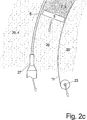
Eine vergrößerte Darstellung im Vertikalschnitt ist in
Das Stützmaterial
Diese Gefahr ist natürlich bei dem frisch entlang des Randes des Formkörpers aufgebrachten Strang
Zu diesem Zweck hat die Düse
Die Düse
Dabei ist in
Dies alles gilt nicht nur für die äußeren Begrenzungsflächen
Anstelle der Hohlräume
Vorzugsweise können die einzelnen Auslassöffnungen einer Düse
Die Düse
Wie die
Eines der Probleme bei einem solchen Herstellen eines Formkörpers
Hierzu können mehrere Maßnahmen einzeln oder einander ergänzend durchgeführt werden:
Wie die
For this purpose, several measures can be carried out individually or as a supplement to one another:
As the
Ergänzend kann beim Ausbringen der beiden Stränge
Dies kann einerseits erreicht werden, indem dem Körpermaterial
Zu diesem Zweck ist die flexible Armierung
For this purpose, the
Dabei besteht das Körpermaterial
This is the
Zu diesem Zweck wird eine neue Schicht
Auf diese Art und Weise werden nicht nur die Bereiche um den Formkörper
Diese zweite Vorgehensweise erschwert aber auch, dass innerhalb des Formkörpers unterschiedliche Materialien verwendet werden, da immer das Gleiche Füllmaterial
Anschließend wird – wie besser in
Dabei wird vorzugsweise mit dem Randbereich des Formkörpers
Dabei muss die Schichtdicke
Um eine saubere Begrenzungsfläche
Anstelle der Trennklinge
Dabei verläuft die Armierung – sei es ein Gewebestreifen oder einzelne, nebeneinander liegende Stränge – vertikal, und ist beispielsweise ursprünglich am Boden des Behälters
Eine solche immer über die oberste Schicht vorstehende Armierung
BezugszeichenlisteLIST OF REFERENCE NUMBERS
- 11
- Behältercontainer
- 2a, b2a, b
- Schichtlayer
- 3, 3a, b3, 3a, b
- Körpermaterialbody material
- 44
- Stützmaterialsupport material
- 55
- Düsejet
- 5'5 '
- Längserstreckunglongitudinal extension
- 5a5a
- Außenseiteoutside
- 66
- Trennmittelrelease agent
- 77
- Binderbinder
- 8a, b8a, b
- Mündungmuzzle
- 99
- Trennklingerelease blade
- 1010
- Hauptebenemain level
- 1111
- Armierungreinforcement
- 1212
- Hohlraumcavity
- 1313
- Strangstrand
- 1414
- Strangstrand
- 1515
- Düsejet
- 1616
- Schichtlayer
- 1717
- Schichtdickelayer thickness
- 1818
- Austrittsrichtungenexit directions
- 19a, b19a, b
- Vorratsbehälterreservoir
- 2020
- Füllmaterialfilling material
- 2121
- Spaltdüseslotted nozzle
- 2222
- Abzieherpuller
- 2323
- ArmierungsspenderArmierungsspender
- 2424
- Luftdüseair nozzle
- 2525
- Roboterarmrobot arm
- 2626
- Auslassoutlet
- 2727
- Düsejet
- 100100
- Formkörpermoldings
- 101101
- Begrenzungsflächenboundary surfaces
- 110110
- FortschrittsrichtungProgress towards
Claims (18)
Priority Applications (4)
| Application Number | Priority Date | Filing Date | Title |
|---|---|---|---|
| DE102012101939A DE102012101939A1 (en) | 2012-03-08 | 2012-03-08 | Method and device for the layered construction of a shaped body |
| ES13158082.1T ES2586694T3 (en) | 2012-03-08 | 2013-03-07 | Procedure for the construction by layers of a body shape |
| US13/789,247 US9457514B2 (en) | 2012-03-08 | 2013-03-07 | Method and device for layered buildup of a shaped element |
| EP13158082.1A EP2636512B1 (en) | 2012-03-08 | 2013-03-07 | Method and apparatus for the layered construction of a moulded part |
Applications Claiming Priority (1)
| Application Number | Priority Date | Filing Date | Title |
|---|---|---|---|
| DE102012101939A DE102012101939A1 (en) | 2012-03-08 | 2012-03-08 | Method and device for the layered construction of a shaped body |
Publications (1)
| Publication Number | Publication Date |
|---|---|
| DE102012101939A1 true DE102012101939A1 (en) | 2013-09-12 |
Family
ID=47877833
Family Applications (1)
| Application Number | Title | Priority Date | Filing Date |
|---|---|---|---|
| DE102012101939A Withdrawn DE102012101939A1 (en) | 2012-03-08 | 2012-03-08 | Method and device for the layered construction of a shaped body |
Country Status (4)
| Country | Link |
|---|---|
| US (1) | US9457514B2 (en) |
| EP (1) | EP2636512B1 (en) |
| DE (1) | DE102012101939A1 (en) |
| ES (1) | ES2586694T3 (en) |
Cited By (2)
| Publication number | Priority date | Publication date | Assignee | Title |
|---|---|---|---|---|
| DE102018132938A1 (en) | 2018-12-19 | 2020-06-25 | Volkswagen Aktiengesellschaft | Process for the generative production of at least one object, use of a printhead and motor vehicle |
| CN111546622A (en) * | 2015-07-31 | 2020-08-18 | 波音公司 | System and method for additive manufacturing of composite parts |
Families Citing this family (118)
| Publication number | Priority date | Publication date | Assignee | Title |
|---|---|---|---|---|
| CN105705319B (en) * | 2013-09-19 | 2018-06-12 | 马克弗巨德有限公司 | Methods of Fiber Reinforced Additive Manufacturing |
| JP6162565B2 (en) * | 2013-10-04 | 2017-07-12 | 株式会社ミマキエンジニアリング | Three-dimensional modeling apparatus and three-dimensional modeling object molding method |
| US10618217B2 (en) | 2013-10-30 | 2020-04-14 | Branch Technology, Inc. | Cellular fabrication and apparatus for additive manufacturing |
| GB2521386A (en) * | 2013-12-18 | 2015-06-24 | Ibm | Improvements in 3D printing |
| DE102014206697A1 (en) | 2014-04-07 | 2015-10-08 | Homag Holzbearbeitungssysteme Gmbh | Device and method for creating solids |
| EP3145798B1 (en) | 2014-05-16 | 2019-11-13 | Divergent Technologies, Inc. | Modular formed nodes for vehicle chassis and their methods of use |
| US9937666B2 (en) | 2014-06-04 | 2018-04-10 | Empire Technology Development Llc | Systems and methods for forming three dimensional objects |
| WO2016003982A1 (en) | 2014-07-02 | 2016-01-07 | Divergent Technologies, Inc. | Systems and methods for fabricating joint members |
| US20160070161A1 (en) * | 2014-09-04 | 2016-03-10 | Massachusetts Institute Of Technology | Illuminated 3D Model |
| CN107206536B (en) | 2014-12-12 | 2019-11-15 | 数字合金公司 | Additive Manufacturing of Metal Structures |
| KR101547820B1 (en) * | 2015-01-27 | 2015-08-28 | 화인케미칼 주식회사 | Equipment for fabrication of three dimensional structures using the transfer pipe |
| JP6235524B2 (en) * | 2015-04-17 | 2017-11-22 | ファナック株式会社 | Sand mold manufacturing system and sand mold manufacturing method for manufacturing sand mold |
| CN104763151B (en) * | 2015-04-21 | 2017-05-03 | 徐晓冰 | 3D printing system for building engineering construction and positioning method of 3D printing system |
| JP6733040B2 (en) * | 2016-04-14 | 2020-07-29 | ブランチ・テクノロジー・インコーポレイテッドBranch Technology, Inc. | Equipment for porous and additive manufacturing |
| KR20190006593A (en) | 2016-06-09 | 2019-01-18 | 디버전트 테크놀로지스, 인크. | Systems and methods for arc and node design and fabrication |
| US10953598B2 (en) * | 2016-11-04 | 2021-03-23 | Continuous Composites Inc. | Additive manufacturing system having vibrating nozzle |
| US11155005B2 (en) | 2017-02-10 | 2021-10-26 | Divergent Technologies, Inc. | 3D-printed tooling and methods for producing same |
| US10759090B2 (en) | 2017-02-10 | 2020-09-01 | Divergent Technologies, Inc. | Methods for producing panels using 3D-printed tooling shells |
| US10363702B2 (en) * | 2017-02-21 | 2019-07-30 | Xyzprinting, Inc. | Three dimensional printing apparatus |
| US10898968B2 (en) | 2017-04-28 | 2021-01-26 | Divergent Technologies, Inc. | Scatter reduction in additive manufacturing |
| US12251884B2 (en) | 2017-04-28 | 2025-03-18 | Divergent Technologies, Inc. | Support structures in additive manufacturing |
| US10703419B2 (en) | 2017-05-19 | 2020-07-07 | Divergent Technologies, Inc. | Apparatus and methods for joining panels |
| US11358337B2 (en) | 2017-05-24 | 2022-06-14 | Divergent Technologies, Inc. | Robotic assembly of transport structures using on-site additive manufacturing |
| US10926329B2 (en) | 2017-05-31 | 2021-02-23 | General Electric Company | Methods and apparatuses to grow compression chambers in powder based additive manufacturing to relieve powder loading on grown part |
| US11123973B2 (en) | 2017-06-07 | 2021-09-21 | Divergent Technologies, Inc. | Interconnected deflectable panel and node |
| US10919230B2 (en) | 2017-06-09 | 2021-02-16 | Divergent Technologies, Inc. | Node with co-printed interconnect and methods for producing same |
| US10781846B2 (en) | 2017-06-19 | 2020-09-22 | Divergent Technologies, Inc. | 3-D-printed components including fasteners and methods for producing same |
| CN107187023A (en) * | 2017-06-20 | 2017-09-22 | 宁夏共享模具有限公司 | A kind of method at the top of use FDM technology printing hollowed mould |
| US10994876B2 (en) | 2017-06-30 | 2021-05-04 | Divergent Technologies, Inc. | Automated wrapping of components in transport structures |
| US11022375B2 (en) | 2017-07-06 | 2021-06-01 | Divergent Technologies, Inc. | Apparatus and methods for additively manufacturing microtube heat exchangers |
| US10895315B2 (en) | 2017-07-07 | 2021-01-19 | Divergent Technologies, Inc. | Systems and methods for implementing node to node connections in mechanized assemblies |
| US10940609B2 (en) | 2017-07-25 | 2021-03-09 | Divergent Technologies, Inc. | Methods and apparatus for additively manufactured endoskeleton-based transport structures |
| US10751800B2 (en) | 2017-07-25 | 2020-08-25 | Divergent Technologies, Inc. | Methods and apparatus for additively manufactured exoskeleton-based transport structures |
| US10605285B2 (en) | 2017-08-08 | 2020-03-31 | Divergent Technologies, Inc. | Systems and methods for joining node and tube structures |
| US10357959B2 (en) | 2017-08-15 | 2019-07-23 | Divergent Technologies, Inc. | Methods and apparatus for additively manufactured identification features |
| US11306751B2 (en) | 2017-08-31 | 2022-04-19 | Divergent Technologies, Inc. | Apparatus and methods for connecting tubes in transport structures |
| US10960611B2 (en) | 2017-09-06 | 2021-03-30 | Divergent Technologies, Inc. | Methods and apparatuses for universal interface between parts in transport structures |
| US11292058B2 (en) | 2017-09-12 | 2022-04-05 | Divergent Technologies, Inc. | Apparatus and methods for optimization of powder removal features in additively manufactured components |
| US10814564B2 (en) | 2017-10-11 | 2020-10-27 | Divergent Technologies, Inc. | Composite material inlay in additively manufactured structures |
| US10668816B2 (en) | 2017-10-11 | 2020-06-02 | Divergent Technologies, Inc. | Solar extended range electric vehicle with panel deployment and emitter tracking |
| US11786971B2 (en) | 2017-11-10 | 2023-10-17 | Divergent Technologies, Inc. | Structures and methods for high volume production of complex structures using interface nodes |
| US10926599B2 (en) | 2017-12-01 | 2021-02-23 | Divergent Technologies, Inc. | Suspension systems using hydraulic dampers |
| US11110514B2 (en) | 2017-12-14 | 2021-09-07 | Divergent Technologies, Inc. | Apparatus and methods for connecting nodes to tubes in transport structures |
| US11085473B2 (en) | 2017-12-22 | 2021-08-10 | Divergent Technologies, Inc. | Methods and apparatus for forming node to panel joints |
| US11534828B2 (en) | 2017-12-27 | 2022-12-27 | Divergent Technologies, Inc. | Assembling structures comprising 3D printed components and standardized components utilizing adhesive circuits |
| US11420262B2 (en) | 2018-01-31 | 2022-08-23 | Divergent Technologies, Inc. | Systems and methods for co-casting of additively manufactured interface nodes |
| US10751934B2 (en) | 2018-02-01 | 2020-08-25 | Divergent Technologies, Inc. | Apparatus and methods for additive manufacturing with variable extruder profiles |
| US11224943B2 (en) | 2018-03-07 | 2022-01-18 | Divergent Technologies, Inc. | Variable beam geometry laser-based powder bed fusion |
| US11267236B2 (en) | 2018-03-16 | 2022-03-08 | Divergent Technologies, Inc. | Single shear joint for node-to-node connections |
| US11872689B2 (en) | 2018-03-19 | 2024-01-16 | Divergent Technologies, Inc. | End effector features for additively manufactured components |
| US11254381B2 (en) | 2018-03-19 | 2022-02-22 | Divergent Technologies, Inc. | Manufacturing cell based vehicle manufacturing system and method |
| US11408216B2 (en) | 2018-03-20 | 2022-08-09 | Divergent Technologies, Inc. | Systems and methods for co-printed or concurrently assembled hinge structures |
| US11613078B2 (en) | 2018-04-20 | 2023-03-28 | Divergent Technologies, Inc. | Apparatus and methods for additively manufacturing adhesive inlet and outlet ports |
| US11214317B2 (en) | 2018-04-24 | 2022-01-04 | Divergent Technologies, Inc. | Systems and methods for joining nodes and other structures |
| US11020800B2 (en) | 2018-05-01 | 2021-06-01 | Divergent Technologies, Inc. | Apparatus and methods for sealing powder holes in additively manufactured parts |
| US10682821B2 (en) | 2018-05-01 | 2020-06-16 | Divergent Technologies, Inc. | Flexible tooling system and method for manufacturing of composite structures |
| US11389816B2 (en) | 2018-05-09 | 2022-07-19 | Divergent Technologies, Inc. | Multi-circuit single port design in additively manufactured node |
| US10691104B2 (en) | 2018-05-16 | 2020-06-23 | Divergent Technologies, Inc. | Additively manufacturing structures for increased spray forming resolution or increased fatigue life |
| US11590727B2 (en) | 2018-05-21 | 2023-02-28 | Divergent Technologies, Inc. | Custom additively manufactured core structures |
| US11441586B2 (en) | 2018-05-25 | 2022-09-13 | Divergent Technologies, Inc. | Apparatus for injecting fluids in node based connections |
| US11035511B2 (en) | 2018-06-05 | 2021-06-15 | Divergent Technologies, Inc. | Quick-change end effector |
| CA3101061A1 (en) | 2018-06-20 | 2019-12-26 | Digital Alloys Incorporated | Multi-diameter wire feeder |
| US11292056B2 (en) | 2018-07-06 | 2022-04-05 | Divergent Technologies, Inc. | Cold-spray nozzle |
| US11269311B2 (en) | 2018-07-26 | 2022-03-08 | Divergent Technologies, Inc. | Spray forming structural joints |
| US10836120B2 (en) | 2018-08-27 | 2020-11-17 | Divergent Technologies, Inc . | Hybrid composite structures with integrated 3-D printed elements |
| US11433557B2 (en) | 2018-08-28 | 2022-09-06 | Divergent Technologies, Inc. | Buffer block apparatuses and supporting apparatuses |
| US11826953B2 (en) | 2018-09-12 | 2023-11-28 | Divergent Technologies, Inc. | Surrogate supports in additive manufacturing |
| US11072371B2 (en) | 2018-10-05 | 2021-07-27 | Divergent Technologies, Inc. | Apparatus and methods for additively manufactured structures with augmented energy absorption properties |
| US11260582B2 (en) | 2018-10-16 | 2022-03-01 | Divergent Technologies, Inc. | Methods and apparatus for manufacturing optimized panels and other composite structures |
| US12115583B2 (en) | 2018-11-08 | 2024-10-15 | Divergent Technologies, Inc. | Systems and methods for adhesive-based part retention features in additively manufactured structures |
| US12194536B2 (en) | 2018-11-13 | 2025-01-14 | Divergent Technologies, Inc. | 3-D printer with manifolds for gas exchange |
| US11504912B2 (en) | 2018-11-20 | 2022-11-22 | Divergent Technologies, Inc. | Selective end effector modular attachment device |
| USD911222S1 (en) | 2018-11-21 | 2021-02-23 | Divergent Technologies, Inc. | Vehicle and/or replica |
| US11449021B2 (en) | 2018-12-17 | 2022-09-20 | Divergent Technologies, Inc. | Systems and methods for high accuracy fixtureless assembly |
| US10663110B1 (en) | 2018-12-17 | 2020-05-26 | Divergent Technologies, Inc. | Metrology apparatus to facilitate capture of metrology data |
| US11529741B2 (en) | 2018-12-17 | 2022-12-20 | Divergent Technologies, Inc. | System and method for positioning one or more robotic apparatuses |
| US11885000B2 (en) | 2018-12-21 | 2024-01-30 | Divergent Technologies, Inc. | In situ thermal treatment for PBF systems |
| US20200232070A1 (en) | 2019-01-18 | 2020-07-23 | Divergent Technologies, Inc. | Aluminum alloy compositions |
| US11203240B2 (en) | 2019-04-19 | 2021-12-21 | Divergent Technologies, Inc. | Wishbone style control arm assemblies and methods for producing same |
| US12314031B1 (en) | 2019-06-27 | 2025-05-27 | Divergent Technologies, Inc. | Incorporating complex geometric features in additively manufactured parts |
| US11853033B1 (en) | 2019-07-26 | 2023-12-26 | Relativity Space, Inc. | Systems and methods for using wire printing process data to predict material properties and part quality |
| US12280554B2 (en) | 2019-11-21 | 2025-04-22 | Divergent Technologies, Inc. | Fixtureless robotic assembly |
| US11912339B2 (en) | 2020-01-10 | 2024-02-27 | Divergent Technologies, Inc. | 3-D printed chassis structure with self-supporting ribs |
| US11590703B2 (en) | 2020-01-24 | 2023-02-28 | Divergent Technologies, Inc. | Infrared radiation sensing and beam control in electron beam additive manufacturing |
| US12194674B2 (en) | 2020-02-14 | 2025-01-14 | Divergent Technologies, Inc. | Multi-material powder bed fusion 3-D printer |
| US11884025B2 (en) | 2020-02-14 | 2024-01-30 | Divergent Technologies, Inc. | Three-dimensional printer and methods for assembling parts via integration of additive and conventional manufacturing operations |
| US11479015B2 (en) | 2020-02-14 | 2022-10-25 | Divergent Technologies, Inc. | Custom formed panels for transport structures and methods for assembling same |
| US12203397B2 (en) | 2020-02-18 | 2025-01-21 | Divergent Technologies, Inc. | Impact energy absorber with integrated engine exhaust noise muffler |
| US11421577B2 (en) | 2020-02-25 | 2022-08-23 | Divergent Technologies, Inc. | Exhaust headers with integrated heat shielding and thermal syphoning |
| US11535322B2 (en) | 2020-02-25 | 2022-12-27 | Divergent Technologies, Inc. | Omni-positional adhesion device |
| US12337541B2 (en) | 2020-02-27 | 2025-06-24 | Divergent Technologies, Inc. | Powder bed fusion additive manufacturing system with desiccant positioned within hopper and ultrasonic transducer |
| US11413686B2 (en) | 2020-03-06 | 2022-08-16 | Divergent Technologies, Inc. | Methods and apparatuses for sealing mechanisms for realizing adhesive connections with additively manufactured components |
| KR20230035571A (en) | 2020-06-10 | 2023-03-14 | 디버전트 테크놀로지스, 인크. | Adaptive production system |
| US11850804B2 (en) | 2020-07-28 | 2023-12-26 | Divergent Technologies, Inc. | Radiation-enabled retention features for fixtureless assembly of node-based structures |
| US11806941B2 (en) | 2020-08-21 | 2023-11-07 | Divergent Technologies, Inc. | Mechanical part retention features for additively manufactured structures |
| EP4210899A4 (en) | 2020-09-08 | 2024-09-25 | Divergent Technologies, Inc. | CREATING AN ASSEMBLY SEQUENCE |
| US12103008B2 (en) | 2020-09-22 | 2024-10-01 | Divergent Technologies, Inc. | Methods and apparatuses for ball milling to produce powder for additive manufacturing |
| US12220819B2 (en) | 2020-10-21 | 2025-02-11 | Divergent Technologies, Inc. | 3-D printed metrology feature geometry and detection |
| FR3115488B1 (en) * | 2020-10-28 | 2023-03-10 | Safran Landing Systems | Means for receiving the powder in an additive manufacturing machine |
| US12311612B2 (en) | 2020-12-18 | 2025-05-27 | Divergent Technologies, Inc. | Direct inject joint architecture enabled by quick cure adhesive |
| US12083596B2 (en) | 2020-12-21 | 2024-09-10 | Divergent Technologies, Inc. | Thermal elements for disassembly of node-based adhesively bonded structures |
| US12226824B2 (en) | 2020-12-22 | 2025-02-18 | Divergent Technologies, Inc. | Three dimensional printer with configurable build plate for rapid powder removal |
| US11872626B2 (en) | 2020-12-24 | 2024-01-16 | Divergent Technologies, Inc. | Systems and methods for floating pin joint design |
| US11947335B2 (en) | 2020-12-30 | 2024-04-02 | Divergent Technologies, Inc. | Multi-component structure optimization for combining 3-D printed and commercially available parts |
| US11928966B2 (en) | 2021-01-13 | 2024-03-12 | Divergent Technologies, Inc. | Virtual railroad |
| US12459377B2 (en) | 2021-01-19 | 2025-11-04 | Divergent Technologies, Inc. | Energy unit cells for primary vehicle structure |
| US12249812B2 (en) | 2021-01-19 | 2025-03-11 | Divergent Technologies, Inc. | Bus bars for printed structural electric battery modules |
| CN116917129A (en) | 2021-03-09 | 2023-10-20 | 戴弗根特技术有限公司 | Rotary additive manufacturing system and method |
| WO2022226411A1 (en) | 2021-04-23 | 2022-10-27 | Divergent Technologies, Inc. | Removal of supports, and other materials from surface, and within hollow 3d printed parts |
| US12138772B2 (en) | 2021-04-30 | 2024-11-12 | Divergent Technologies, Inc. | Mobile parts table |
| US12502792B2 (en) | 2021-05-24 | 2025-12-23 | Divergent Technologies, Inc. | Robotic gripper apparatus |
| US12365965B2 (en) | 2021-07-01 | 2025-07-22 | Divergent Technologies, Inc. | Al—Mg—Si based near-eutectic alloy composition for high strength and stiffness applications |
| US11865617B2 (en) | 2021-08-25 | 2024-01-09 | Divergent Technologies, Inc. | Methods and apparatuses for wide-spectrum consumption of output of atomization processes across multi-process and multi-scale additive manufacturing modalities |
| US12351238B2 (en) | 2021-11-02 | 2025-07-08 | Divergent Technologies, Inc. | Motor nodes |
| US12152629B2 (en) | 2022-01-25 | 2024-11-26 | Divergent Technologies, Inc. | Attachment structure having a connection member with multiple attachment features |
| EP4469265A4 (en) | 2022-01-25 | 2025-06-25 | Divergent Technologies, Inc. | CORRECTIONS BASED ON MEASUREMENTS FOR THE ENTIRE STRUCTURE |
| US20230390999A1 (en) * | 2022-06-03 | 2023-12-07 | Sakuu Corporation | Apparatus and method of binder jetting 3d printing |
| DE102022134212A1 (en) * | 2022-12-20 | 2024-06-20 | Ottobock Se & Co. Kgaa | Method and device for producing an object |
Citations (2)
| Publication number | Priority date | Publication date | Assignee | Title |
|---|---|---|---|---|
| DE19853978C1 (en) * | 1998-11-23 | 2000-05-25 | Fraunhofer Ges Forschung | Apparatus for selective laser smelting comprises a roller that moves over the processing surface using an element to distribute powder |
| EP1391289B1 (en) * | 2002-08-01 | 2006-01-04 | General Motors Corporation | Low shrink low density laminate formulation |
Family Cites Families (12)
| Publication number | Priority date | Publication date | Assignee | Title |
|---|---|---|---|---|
| US5256340A (en) * | 1988-04-18 | 1993-10-26 | 3D Systems, Inc. | Method of making a three-dimensional object by stereolithography |
| US5216616A (en) * | 1989-06-26 | 1993-06-01 | Masters William E | System and method for computer automated manufacture with reduced object shape distortion |
| US5204055A (en) | 1989-12-08 | 1993-04-20 | Massachusetts Institute Of Technology | Three-dimensional printing techniques |
| US5999184A (en) * | 1990-10-30 | 1999-12-07 | 3D Systems, Inc. | Simultaneous multiple layer curing in stereolithography |
| US5503785A (en) * | 1994-06-02 | 1996-04-02 | Stratasys, Inc. | Process of support removal for fused deposition modeling |
| US6658314B1 (en) * | 1999-10-06 | 2003-12-02 | Objet Geometries Ltd. | System and method for three dimensional model printing |
| ES2230086T3 (en) * | 2000-03-24 | 2005-05-01 | Voxeljet Technology Gmbh | METHOD AND APPLIANCE FOR MANUFACTURING A STRUCTURAL PART BY MULTI-LAYER DEPOSITION TECHNIQUE AND MALE MOLDING MANUFACTURED WITH THE METHOD. |
| US20040005374A1 (en) * | 2002-05-16 | 2004-01-08 | Subhash Narang | Creating objects through X and Z movement of print heads |
| US7255825B2 (en) * | 2004-03-10 | 2007-08-14 | Hewlett-Packard Development Company, L.P. | Materials and methods for freeform fabrication of solid three-dimensional objects using fusible, water-containing support materials |
| WO2005107981A2 (en) * | 2004-05-04 | 2005-11-17 | Optomec Design Company | Greater angle and overhanging materials deposition |
| US7236166B2 (en) * | 2005-01-18 | 2007-06-26 | Stratasys, Inc. | High-resolution rapid manufacturing |
| US8460755B2 (en) * | 2011-04-07 | 2013-06-11 | Stratasys, Inc. | Extrusion-based additive manufacturing process with part annealing |
-
2012
- 2012-03-08 DE DE102012101939A patent/DE102012101939A1/en not_active Withdrawn
-
2013
- 2013-03-07 US US13/789,247 patent/US9457514B2/en active Active
- 2013-03-07 ES ES13158082.1T patent/ES2586694T3/en active Active
- 2013-03-07 EP EP13158082.1A patent/EP2636512B1/en active Active
Patent Citations (2)
| Publication number | Priority date | Publication date | Assignee | Title |
|---|---|---|---|---|
| DE19853978C1 (en) * | 1998-11-23 | 2000-05-25 | Fraunhofer Ges Forschung | Apparatus for selective laser smelting comprises a roller that moves over the processing surface using an element to distribute powder |
| EP1391289B1 (en) * | 2002-08-01 | 2006-01-04 | General Motors Corporation | Low shrink low density laminate formulation |
Cited By (3)
| Publication number | Priority date | Publication date | Assignee | Title |
|---|---|---|---|---|
| CN111546622A (en) * | 2015-07-31 | 2020-08-18 | 波音公司 | System and method for additive manufacturing of composite parts |
| DE102018132938A1 (en) | 2018-12-19 | 2020-06-25 | Volkswagen Aktiengesellschaft | Process for the generative production of at least one object, use of a printhead and motor vehicle |
| WO2020126427A1 (en) | 2018-12-19 | 2020-06-25 | Volkswagen Aktiengesellschaft | Method for the generative manufacture of at least one article, use of a printhead and motor vehicle |
Also Published As
| Publication number | Publication date |
|---|---|
| EP2636512B1 (en) | 2016-05-18 |
| ES2586694T3 (en) | 2016-10-18 |
| EP2636512A3 (en) | 2013-10-16 |
| US20130234369A1 (en) | 2013-09-12 |
| EP2636512A2 (en) | 2013-09-11 |
| US9457514B2 (en) | 2016-10-04 |
Similar Documents
| Publication | Publication Date | Title |
|---|---|---|
| EP2636512B1 (en) | Method and apparatus for the layered construction of a moulded part | |
| DE102014112447B4 (en) | 3D printer, 3D printer arrangement and generative manufacturing process | |
| EP3393765B1 (en) | Device and method for producing a three-dimensional object with a fibre feeding device | |
| DE102007054424A1 (en) | Device for producing molded parts from fiber material | |
| DE102011007957A1 (en) | Device and method for constructing a layer body with at least one body limiting the construction field and adjustable in terms of its position | |
| DE102008027315A1 (en) | Forming molded parts made of successive layers, whose boundary surfaces form part of surface of molded parts, by forming molded part as composite part from different materials, and applying material forming layers on base or previous layer | |
| DE1504986A1 (en) | Method and device for the production of fiber-reinforced articles from plastic or resin material | |
| WO2020245301A1 (en) | Method for producing at least one component in a 3d printing method, and 3d printer | |
| DE102007060739B4 (en) | Method and device for producing fiber composite components | |
| EP3705250B1 (en) | Method for producing a concrete component and concrete part producing device | |
| EP2447049B1 (en) | Method and device for producing fibre composite components | |
| EP3243633A1 (en) | 3d printing of workpieces with a cellular structure, in particular plastic | |
| DE102010004678A1 (en) | Apparatus and method for direct sliver spraying | |
| DE102011082192B4 (en) | Process and device for producing prepregs from winding processes | |
| EP3291961A1 (en) | Method and device for producing large-volume containers with a flange by plastic blow molding | |
| EP3012083B1 (en) | Method and tool for producing a component, component | |
| DE102023107846A1 (en) | Device and method for additive manufacturing of a component | |
| WO2024112981A1 (en) | 3d building-material printer for the 3d printing of building-material strands and for connecting the building-material strands via cross-reinforcement elements | |
| EP4221956A1 (en) | Method for producing a component by means of additive manufacturing | |
| DE102013010788A1 (en) | Slot die for extrusion device | |
| DE102013221387A1 (en) | Installation space and method for the production of workpieces in the layer construction process | |
| DE3610782A1 (en) | Process and device for producing a heat-insulating building block (brick) | |
| DE102020125720A1 (en) | Process for manufacturing a component using additive manufacturing | |
| DE3815063A1 (en) | METHOD AND DEVICE FOR PRODUCING A COMPONENT FROM PLASTIC | |
| DE102006046130A1 (en) | Producing a coated large-area part comprises varying the amount and/or composition of polyurethane material deposited on the part in lines or sections |
Legal Events
| Date | Code | Title | Description |
|---|---|---|---|
| R012 | Request for examination validly filed | ||
| R016 | Response to examination communication | ||
| R016 | Response to examination communication | ||
| R016 | Response to examination communication | ||
| R082 | Change of representative |
Representative=s name: PATENTANWAELTE WEICKMANN & WEICKMANN, DE Representative=s name: WEICKMANN & WEICKMANN PATENTANWAELTE - RECHTSA, DE Representative=s name: WEICKMANN & WEICKMANN PATENT- UND RECHTSANWAEL, DE |
|
| R079 | Amendment of ipc main class |
Free format text: PREVIOUS MAIN CLASS: B29C0067000000 Ipc: B29C0064106000 |
|
| R016 | Response to examination communication | ||
| R120 | Application withdrawn or ip right abandoned |