DE102012017205A1 - Method and device for testing sensors to be applied to the skin of a patient for the detection of fluid or moisture - Google Patents
Method and device for testing sensors to be applied to the skin of a patient for the detection of fluid or moisture Download PDFInfo
- Publication number
- DE102012017205A1 DE102012017205A1 DE102012017205.2A DE102012017205A DE102012017205A1 DE 102012017205 A1 DE102012017205 A1 DE 102012017205A1 DE 102012017205 A DE102012017205 A DE 102012017205A DE 102012017205 A1 DE102012017205 A1 DE 102012017205A1
- Authority
- DE
- Germany
- Prior art keywords
- moisture
- sensors
- torsion
- patient
- sensor
- Prior art date
- Legal status (The legal status is an assumption and is not a legal conclusion. Google has not performed a legal analysis and makes no representation as to the accuracy of the status listed.)
- Withdrawn
Links
- 238000000034 method Methods 0.000 title claims abstract description 35
- 238000012360 testing method Methods 0.000 title claims abstract description 27
- 238000001514 detection method Methods 0.000 title abstract description 5
- 239000012530 fluid Substances 0.000 title description 2
- 238000004519 manufacturing process Methods 0.000 claims abstract description 12
- 239000007788 liquid Substances 0.000 claims abstract description 7
- 239000004744 fabric Substances 0.000 claims description 12
- 238000011156 evaluation Methods 0.000 claims description 5
- 238000005259 measurement Methods 0.000 claims description 5
- 239000012876 carrier material Substances 0.000 claims description 2
- 210000000245 forearm Anatomy 0.000 abstract description 13
- 239000008280 blood Substances 0.000 abstract description 9
- 210000004369 blood Anatomy 0.000 abstract description 9
- 230000002792 vascular Effects 0.000 abstract description 9
- 238000012544 monitoring process Methods 0.000 abstract description 7
- 239000004753 textile Substances 0.000 description 8
- 239000004020 conductor Substances 0.000 description 7
- 210000000689 upper leg Anatomy 0.000 description 7
- 238000003908 quality control method Methods 0.000 description 4
- 210000002414 leg Anatomy 0.000 description 3
- 239000000463 material Substances 0.000 description 3
- 238000010998 test method Methods 0.000 description 3
- 238000005452 bending Methods 0.000 description 2
- 230000006835 compression Effects 0.000 description 2
- 238000007906 compression Methods 0.000 description 2
- 230000001351 cycling effect Effects 0.000 description 2
- 230000002950 deficient Effects 0.000 description 2
- 238000002474 experimental method Methods 0.000 description 2
- 238000010972 statistical evaluation Methods 0.000 description 2
- 238000009941 weaving Methods 0.000 description 2
- BUHVIAUBTBOHAG-FOYDDCNASA-N (2r,3r,4s,5r)-2-[6-[[2-(3,5-dimethoxyphenyl)-2-(2-methylphenyl)ethyl]amino]purin-9-yl]-5-(hydroxymethyl)oxolane-3,4-diol Chemical compound COC1=CC(OC)=CC(C(CNC=2C=3N=CN(C=3N=CN=2)[C@H]2[C@@H]([C@H](O)[C@@H](CO)O2)O)C=2C(=CC=CC=2)C)=C1 BUHVIAUBTBOHAG-FOYDDCNASA-N 0.000 description 1
- 230000006378 damage Effects 0.000 description 1
- 230000001419 dependent effect Effects 0.000 description 1
- 238000009658 destructive testing Methods 0.000 description 1
- 238000000502 dialysis Methods 0.000 description 1
- 238000012377 drug delivery Methods 0.000 description 1
- 238000001631 haemodialysis Methods 0.000 description 1
- 238000010438 heat treatment Methods 0.000 description 1
- 230000000322 hemodialysis Effects 0.000 description 1
- 230000002427 irreversible effect Effects 0.000 description 1
- 238000012545 processing Methods 0.000 description 1
- 238000007670 refining Methods 0.000 description 1
- 230000000284 resting effect Effects 0.000 description 1
- 230000002441 reversible effect Effects 0.000 description 1
- 238000004088 simulation Methods 0.000 description 1
- 238000005406 washing Methods 0.000 description 1
Images


Classifications
-
- A—HUMAN NECESSITIES
- A61—MEDICAL OR VETERINARY SCIENCE; HYGIENE
- A61B—DIAGNOSIS; SURGERY; IDENTIFICATION
- A61B5/00—Measuring for diagnostic purposes; Identification of persons
- A61B5/02—Detecting, measuring or recording for evaluating the cardiovascular system, e.g. pulse, heart rate, blood pressure or blood flow
- A61B5/02042—Determining blood loss or bleeding, e.g. during a surgical procedure
-
- G—PHYSICS
- G01—MEASURING; TESTING
- G01R—MEASURING ELECTRIC VARIABLES; MEASURING MAGNETIC VARIABLES
- G01R35/00—Testing or calibrating of apparatus covered by the other groups of this subclass
-
- A—HUMAN NECESSITIES
- A61—MEDICAL OR VETERINARY SCIENCE; HYGIENE
- A61B—DIAGNOSIS; SURGERY; IDENTIFICATION
- A61B5/00—Measuring for diagnostic purposes; Identification of persons
- A61B5/145—Measuring characteristics of blood in vivo, e.g. gas concentration or pH-value ; Measuring characteristics of body fluids or tissues, e.g. interstitial fluid or cerebral tissue
- A61B5/1495—Calibrating or testing of in-vivo probes
-
- A—HUMAN NECESSITIES
- A61—MEDICAL OR VETERINARY SCIENCE; HYGIENE
- A61B—DIAGNOSIS; SURGERY; IDENTIFICATION
- A61B5/00—Measuring for diagnostic purposes; Identification of persons
- A61B5/44—Detecting, measuring or recording for evaluating the integumentary system, e.g. skin, hair or nails
- A61B5/441—Skin evaluation, e.g. for skin disorder diagnosis
- A61B5/443—Evaluating skin constituents, e.g. elastin, melanin, water
-
- A—HUMAN NECESSITIES
- A61—MEDICAL OR VETERINARY SCIENCE; HYGIENE
- A61F—FILTERS IMPLANTABLE INTO BLOOD VESSELS; PROSTHESES; DEVICES PROVIDING PATENCY TO, OR PREVENTING COLLAPSING OF, TUBULAR STRUCTURES OF THE BODY, e.g. STENTS; ORTHOPAEDIC, NURSING OR CONTRACEPTIVE DEVICES; FOMENTATION; TREATMENT OR PROTECTION OF EYES OR EARS; BANDAGES, DRESSINGS OR ABSORBENT PADS; FIRST-AID KITS
- A61F13/00—Bandages or dressings; Absorbent pads
- A61F13/15—Absorbent pads, e.g. sanitary towels, swabs or tampons for external or internal application to the body; Supporting or fastening means therefor; Tampon applicators
- A61F13/42—Absorbent pads, e.g. sanitary towels, swabs or tampons for external or internal application to the body; Supporting or fastening means therefor; Tampon applicators with wetness indicator or alarm
-
- A—HUMAN NECESSITIES
- A61—MEDICAL OR VETERINARY SCIENCE; HYGIENE
- A61M—DEVICES FOR INTRODUCING MEDIA INTO, OR ONTO, THE BODY; DEVICES FOR TRANSDUCING BODY MEDIA OR FOR TAKING MEDIA FROM THE BODY; DEVICES FOR PRODUCING OR ENDING SLEEP OR STUPOR
- A61M1/00—Suction or pumping devices for medical purposes; Devices for carrying-off, for treatment of, or for carrying-over, body-liquids; Drainage systems
- A61M1/36—Other treatment of blood in a by-pass of the natural circulatory system, e.g. temperature adaptation, irradiation ; Extra-corporeal blood circuits
- A61M1/3621—Extra-corporeal blood circuits
- A61M1/3653—Interfaces between patient blood circulation and extra-corporal blood circuit
- A61M1/3656—Monitoring patency or flow at connection sites; Detecting disconnections
-
- A—HUMAN NECESSITIES
- A61—MEDICAL OR VETERINARY SCIENCE; HYGIENE
- A61M—DEVICES FOR INTRODUCING MEDIA INTO, OR ONTO, THE BODY; DEVICES FOR TRANSDUCING BODY MEDIA OR FOR TAKING MEDIA FROM THE BODY; DEVICES FOR PRODUCING OR ENDING SLEEP OR STUPOR
- A61M1/00—Suction or pumping devices for medical purposes; Devices for carrying-off, for treatment of, or for carrying-over, body-liquids; Drainage systems
- A61M1/36—Other treatment of blood in a by-pass of the natural circulatory system, e.g. temperature adaptation, irradiation ; Extra-corporeal blood circuits
- A61M1/3621—Extra-corporeal blood circuits
- A61M1/3653—Interfaces between patient blood circulation and extra-corporal blood circuit
- A61M1/3659—Cannulae pertaining to extracorporeal circulation
-
- G—PHYSICS
- G01—MEASURING; TESTING
- G01M—TESTING STATIC OR DYNAMIC BALANCE OF MACHINES OR STRUCTURES; TESTING OF STRUCTURES OR APPARATUS, NOT OTHERWISE PROVIDED FOR
- G01M3/00—Investigating fluid-tightness of structures
- G01M3/02—Investigating fluid-tightness of structures by using fluid or vacuum
- G01M3/04—Investigating fluid-tightness of structures by using fluid or vacuum by detecting the presence of fluid at the leakage point
- G01M3/16—Investigating fluid-tightness of structures by using fluid or vacuum by detecting the presence of fluid at the leakage point using electric detection means
-
- G—PHYSICS
- G01—MEASURING; TESTING
- G01R—MEASURING ELECTRIC VARIABLES; MEASURING MAGNETIC VARIABLES
- G01R3/00—Apparatus or processes specially adapted for the manufacture or maintenance of measuring instruments, e.g. of probe tips
-
- A—HUMAN NECESSITIES
- A61—MEDICAL OR VETERINARY SCIENCE; HYGIENE
- A61B—DIAGNOSIS; SURGERY; IDENTIFICATION
- A61B2562/00—Details of sensors; Constructional details of sensor housings or probes; Accessories for sensors
- A61B2562/02—Details of sensors specially adapted for in-vivo measurements
- A61B2562/029—Humidity sensors
-
- A—HUMAN NECESSITIES
- A61—MEDICAL OR VETERINARY SCIENCE; HYGIENE
- A61B—DIAGNOSIS; SURGERY; IDENTIFICATION
- A61B2562/00—Details of sensors; Constructional details of sensor housings or probes; Accessories for sensors
- A61B2562/12—Manufacturing methods specially adapted for producing sensors for in-vivo measurements
-
- A—HUMAN NECESSITIES
- A61—MEDICAL OR VETERINARY SCIENCE; HYGIENE
- A61B—DIAGNOSIS; SURGERY; IDENTIFICATION
- A61B5/00—Measuring for diagnostic purposes; Identification of persons
- A61B5/68—Arrangements of detecting, measuring or recording means, e.g. sensors, in relation to patient
- A61B5/6801—Arrangements of detecting, measuring or recording means, e.g. sensors, in relation to patient specially adapted to be attached to or worn on the body surface
- A61B5/683—Means for maintaining contact with the body
- A61B5/6831—Straps, bands or harnesses
-
- A—HUMAN NECESSITIES
- A61—MEDICAL OR VETERINARY SCIENCE; HYGIENE
- A61F—FILTERS IMPLANTABLE INTO BLOOD VESSELS; PROSTHESES; DEVICES PROVIDING PATENCY TO, OR PREVENTING COLLAPSING OF, TUBULAR STRUCTURES OF THE BODY, e.g. STENTS; ORTHOPAEDIC, NURSING OR CONTRACEPTIVE DEVICES; FOMENTATION; TREATMENT OR PROTECTION OF EYES OR EARS; BANDAGES, DRESSINGS OR ABSORBENT PADS; FIRST-AID KITS
- A61F13/00—Bandages or dressings; Absorbent pads
- A61F2013/00361—Plasters
- A61F2013/00365—Plasters use
- A61F2013/00429—Plasters use for conducting tests
-
- A—HUMAN NECESSITIES
- A61—MEDICAL OR VETERINARY SCIENCE; HYGIENE
- A61M—DEVICES FOR INTRODUCING MEDIA INTO, OR ONTO, THE BODY; DEVICES FOR TRANSDUCING BODY MEDIA OR FOR TAKING MEDIA FROM THE BODY; DEVICES FOR PRODUCING OR ENDING SLEEP OR STUPOR
- A61M2209/00—Ancillary equipment
- A61M2209/02—Equipment for testing the apparatus
-
- Y—GENERAL TAGGING OF NEW TECHNOLOGICAL DEVELOPMENTS; GENERAL TAGGING OF CROSS-SECTIONAL TECHNOLOGIES SPANNING OVER SEVERAL SECTIONS OF THE IPC; TECHNICAL SUBJECTS COVERED BY FORMER USPC CROSS-REFERENCE ART COLLECTIONS [XRACs] AND DIGESTS
- Y10—TECHNICAL SUBJECTS COVERED BY FORMER USPC
- Y10T—TECHNICAL SUBJECTS COVERED BY FORMER US CLASSIFICATION
- Y10T29/00—Metal working
- Y10T29/49—Method of mechanical manufacture
- Y10T29/49002—Electrical device making
- Y10T29/49004—Electrical device making including measuring or testing of device or component part
Landscapes
- Health & Medical Sciences (AREA)
- Life Sciences & Earth Sciences (AREA)
- Heart & Thoracic Surgery (AREA)
- Engineering & Computer Science (AREA)
- Veterinary Medicine (AREA)
- Public Health (AREA)
- General Health & Medical Sciences (AREA)
- Animal Behavior & Ethology (AREA)
- Biomedical Technology (AREA)
- Vascular Medicine (AREA)
- Physics & Mathematics (AREA)
- Surgery (AREA)
- Cardiology (AREA)
- Medical Informatics (AREA)
- Molecular Biology (AREA)
- Pathology (AREA)
- Biophysics (AREA)
- Anesthesiology (AREA)
- Hematology (AREA)
- General Physics & Mathematics (AREA)
- Physiology (AREA)
- Optics & Photonics (AREA)
- Nuclear Medicine, Radiotherapy & Molecular Imaging (AREA)
- Epidemiology (AREA)
- Dermatology (AREA)
- External Artificial Organs (AREA)
Abstract
Die Erfindung betrifft ein Verfahren und eine Vorrichtung zum Prüfen von auf die Haut eines Patienten aufzubringenden Sensoren zum Erkennen von Flüssigkeit oder Feuchtigkeit, insbesondere zur Überwachung des Gefäßzugangs bei einer extrakorporalen Blutbehandlung, bei der Blut eines Patienten über eine arterielle Schlauchleitung, die eine arterielle Kanüle aufweist, von dem Patienten abgeführt wird, und über eine venöse Schlauchleitung, die eine venöse Punktionskanüle aufweist, dem Patienten zugeführt wird. Darüber hinaus betrifft die Erfindung ein Verfahren zum Produzieren von auf die Haut eines Patienten aufzubringenden Sensoren zum Erkennen von Flüssigkeit oder Feuchtigkeit. Das erfindungsgemäße Verfahren und die erfindungsgemäße Vorrichtung beruhen auf der Prüfung eines oder mehrerer Feuchtigkeitssensoren, die der laufenden Produktion entnommen werden. Die Erfindung sieht eine Vielzahl von Torsionen des auf einen Torsionskörper (20) aufgebrachten Feuchtigkeitssensors (80) vor. Dadurch werden die mechanischen Beanspruchungen nachempfunden, wie sie in der Praxis auftreten können, wenn der Feuchtigkeitssensor auf die Haut des Patienten, insbesondere dessen Unterarm aufgebracht, insbesondere aufgeklebt wird.The invention relates to a method and a device for testing sensors to be applied to the skin of a patient for the detection of liquid or moisture, in particular for monitoring vascular access in the case of extracorporeal blood treatment, in the blood of a patient via an arterial hose line which has an arterial cannula , is discharged from the patient, and is fed to the patient via a venous hose line which has a venous puncture cannula. Furthermore, the invention relates to a method for producing sensors to be applied to the skin of a patient for the detection of liquid or moisture. The method according to the invention and the device according to the invention are based on the testing of one or more moisture sensors which are taken from the current production. The invention provides for a large number of torsions of the moisture sensor (80) applied to a torsion body (20). This simulates the mechanical stresses that can occur in practice when the moisture sensor is applied, in particular glued, to the patient's skin, in particular his forearm.
Description
Die Erfindung betrifft ein Verfahren und eine Vorrichtung zum Prüfen von auf die Haut eines Patienten aufzubringenden Sensoren zum Erkennen von Flüssigkeit oder Feuchtigkeit, insbesondere Feuchtigkeitssensoren zur Überwachung des Gefäßzugangs bei einer extrakorporalen Blutbehandlung, bei der Blut eines Patienten über eine arterielle Schlauchleitung, die eine arterielle Kanüle aufweist, von dem Patienten abgeführt wird, und über eine venöse Schlauchleitung, die eine venöse Punktionskanüle aufweist, dem Patienten zugeführt wird. Darüber hinaus betrifft die Erfindung ein Verfahren zum Produzieren von auf die Haut eines Patienten aufzubringenden Sensoren zum Erkennen von Flüssigkeit oder Feuchtigkeit.The invention relates to a method and a device for testing sensors for the detection of fluid or moisture to be applied to the skin of a patient, in particular moisture sensors for monitoring the vascular access in an extracorporeal blood treatment, in the blood of a patient via an arterial tube, which is an arterial cannula , is discharged from the patient, and is supplied to the patient via a venous tubing having a venous puncture cannula. Moreover, the invention relates to a method of producing sensors for applying liquid or moisture to the skin of a patient.
Aus der
Die
Neben den resistiven Sensoren sind auch kapazitive Feuchtigkeitssensoren bekannt, die über eine elektrisch leitende Struktur verfügen, die sich aus mehreren elektrisch leitenden Abschnitten zusammensetzt.In addition to the resistive sensors, capacitive humidity sensors are also known which have an electrically conductive structure composed of a plurality of electrically conductive sections.
Die bekannten Feuchtigkeitssensoren zur Überwachung eines Gefäßzugangs, die über eine elektrisch leitende Struktur verfügen, die sich aus mehreren elektrisch leitenden Abschnitten zusammensetzt, erlauben eine Überprüfung der Funktionsfähigkeit dadurch, dass die elektrischen Eigenschaften des Sensors unter definierten Bedingungen gemessen und mit als Referenzwert vorgegebenen Eigenschaften verglichen werden. Wenn die Abweichungen zwischen den gemessenen Eigenschaften und den als Referenzwert vorgegebenen Eigenschaften ein vorbestimmtes Maß überschreiten oder unterschreiten, beispielsweise wegen eines Leiterbahnbruchs oder Kurzschlusses, wird auf einen fehlerhaften Feuchtigkeitssensor geschlossen.The known moisture sensors for monitoring a vascular access, which have an electrically conductive structure, which is composed of a plurality of electrically conductive portions, allow a check of the functionality by the electrical properties of the sensor are measured under defined conditions and compared with predetermined reference properties properties , If the deviations between the measured properties and the properties given as a reference value exceed or fall below a predetermined level, for example because of a conductor break or short circuit, a faulty moisture sensor is concluded.
Die bekannten textilen Feuchtigkeitssensoren werden an der Punktionsstelle auf die Haut des Patienten aufgebracht. Zur Überwachung eines Gefäßzugangs bei einer extrakorporalen Blutbehandlung werden die Feuchtigkeitssensoren beispielsweise auf den Unterarm des Patienten aufgeklebt. Der Unterarm mit Gefäßzugang wird von dem Patienten während der extrakorporalen Blutbehandlung im Allgemeinen ruhig gehalten. Wenn der Patient während der Blutbehandlung aber den Unterarm bewegt, ist der Feuchtigkeitssensor mechanischen Beanspruchungen ausgesetzt, so dass die leitenden Abschnitte der elektrisch leitenden Struktur wiederholt Zug-Druck- oder Biegebeanspruchungen ausgesetzt sind. Das Problem der mechanischen Beanspruchung stellt sich bei textilen Feuchtigkeitssensoren, bei denen Kett- und Schussfäden die elektrisch leitende Struktur bilden. Aber auch bei gedruckten Leiterbahnen, besteht die Gefahr des Leiterbahnbruchs durch Mikrorisse.The known textile moisture sensors are applied to the skin of the patient at the puncture site. To monitor a vascular access in an extracorporeal blood treatment, the moisture sensors are glued, for example, on the forearm of the patient. The vascular access forearm is generally kept quiet by the patient during extracorporeal blood treatment. However, as the patient moves the forearm during the blood treatment, the moisture sensor is subjected to mechanical stresses such that the conductive portions of the electrically conductive structure are repeatedly subjected to tensile, compression or bending stresses. The problem of mechanical stress arises in textile moisture sensors in which warp and weft threads form the electrically conductive structure. But even with printed conductors, there is a risk of conductor breakage by microcracks.
Die textilen Feuchtigkeitssensoren mit gewebten oder gedruckten Leiterbahnen haben den Vorteil, dass sich die Sensoren in großen Stückzahlen auf einer gemeinsamen Gewebebahn kostengünstig herstellen lassen. Nach dem Weben und gegebenenfalls weiteren Bearbeitungsschritten werden die einzelnen Feuchtigkeitssensoren voneinander separiert.The textile moisture sensors with woven or printed conductor tracks have the advantage that the sensors can be produced inexpensively in large quantities on a common fabric web. After weaving and optionally further processing steps, the individual moisture sensors are separated from each other.
Der Erfindung liegt die Aufgabe zugrunde, ein Verfahren für die Produktion von Feuchtigkeitssensoren mit einer elektrisch leitenden Struktur aus mehreren elektrisch leitenden Abschnitten in großen Stückzahlen anzugeben, wobei die hergestellten Feuchtigkeitssensoren hohen Qualitätsanforderungen genügen.The invention has for its object to provide a method for the production of moisture sensors with an electrically conductive structure of a plurality of electrically conductive sections in large numbers, the moisture sensors produced meet high quality requirements.
Eine weitere Aufgabe der Erfindung liegt darin, ein Verfahren zur Qualitätskontrolle von Feuchtigkeitssensoren mit einer elektrisch leitenden Struktur aus mehreren elektrisch leitenden Abschnitten anzugeben.Another object of the invention is to provide a method for quality control of moisture sensors having an electrically conductive structure of a plurality of electrically conductive sections.
Darüber hinaus ist eine Aufgabe der Erfindung, eine Vorrichtung zu schaffen, die eine zuverlässige Qualitätskontrolle der Feuchtigkeitssensoren erlaubt.Moreover, it is an object of the invention to provide a device which allows reliable quality control of the humidity sensors.
Die Lösung dieser Aufgaben erfolgt erfindungsgemäß mit den Merkmalen der unabhängigen Patentansprüche. Die abhängigen Ansprüche betreffen bevorzugte Ausführungsformen der Erfindung.The solution of these objects is achieved according to the invention with the features of the independent claims. The dependent claims relate to preferred embodiments of the invention.
Das erfindungsgemäße Verfahren und die erfindungsgemäße Vorrichtung beruhen auf der zerstörenden Prüfung eines oder mehrerer Feuchtigkeitssensoren, die der laufenden Produktion als Probe entnommen werden. Die Erfindung sieht eine komplexe mechanische Beanspruchung der Feuchtigkeitssensoren vor, die einer Beanspruchung nachempfunden wird, die in der Praxis auftritt, wenn der Feuchtigkeitssensor auf die Haut des Patienten, insbesondere dessen Unterarm aufgebracht, insbesondere aufgeklebt wird. Dabei können die mechanischen Beanspruchungen simuliert werden, die im ungünstigsten Fall auftreten können. Für den Fall, dass der oder die Feuchtigkeitssensoren einer Charge bei der Prüfung den gesetzten Anforderungen nicht entsprechen sollten, wird auf eine Fehlerhaftigkeit der Charge geschlossen. Es können dann weitere Proben genommen oder die gesamte Charge verworfen werden.The inventive method and the device according to the invention are based on the destructive testing of one or more Moisture sensors sampled from current production. The invention provides a complex mechanical stress on the moisture sensors, which is modeled on a stress that occurs in practice, when the moisture sensor is applied to the skin of the patient, in particular his forearm, in particular glued. In this case, the mechanical stresses can be simulated, which can occur in the worst case. In the event that the moisture sensor or sensors of a batch during the test should not meet the set requirements, it is concluded that the batch is defective. It can then be taken more samples or discarded the entire batch.
Es hat sich in Versuchen gezeigt, dass die mechanischen Beanspruchungen des Feuchtigkeitssensors auf der Haut des Patienten dadurch simuliert werden können, wenn der Feuchtigkeitssensor auf einen verformbaren Körper aufgebracht wird, der mehrfach verformt wird. Dabei treten in dem Feuchtigkeitssensor wechselnde Zug-, Druck- und Biegespannungen auf, die zu entsprechenden reversiblen und irreversiblen Verformungen im mikroskopischen Bereich und sogar zum Bruch der Leiterbahnen führen können. Die Prüfung entspricht also einer künstlichen Beanspruchung unter realitätsnahen Bedingungen, wobei eine vorgegebene Anzahl von Lastwechseln erzeugt wird. Der Feuchtigkeitssensor kann auf die Oberfläche des elastischen Körpers geklebt werden. Es ist aber auch jede andere Art der Befestigung des Feuchtigkeitssensors möglich. Entscheidend ist, dass der Feuchtigkeitssensor mit seiner Unterseite fest mit der Oberseite des elastischen Körpers verbunden ist.It has been shown in experiments that the mechanical stresses of the moisture sensor on the skin of the patient can be simulated by applying the moisture sensor to a deformable body which is deformed several times. In this case, alternating tensile, compressive and bending stresses occur in the moisture sensor, which can lead to corresponding reversible and irreversible deformations in the microscopic range and even to breakage of the conductor tracks. The test thus corresponds to an artificial load under realistic conditions, whereby a predetermined number of load changes is generated. The moisture sensor may be adhered to the surface of the elastic body. But it is also possible any other way of attaching the humidity sensor. It is crucial that the moisture sensor is firmly connected with its underside to the top of the elastic body.
Weiterhin hat sich in Versuchen gezeigt, dass eine besonders realitätsnahe Simulation der beim Tragen des Feuchtigkeitssensors auftretenden mechanischen Beanspruchungen dann möglich ist, wenn der Feuchtigkeitssensor auf die Oberfläche eines elastischen Torsionskörpers aufgebracht und der Torsionskörper mehrfach tordiert wird, beispielsweise oszillierend tordiert wird. Besonders bevorzugt wird ein zylindrischer Torsionskörper, auf dessen Mantelfläche der Feuchtigkeitssensor aufgebracht wird.Furthermore, it has been shown in tests that a particularly realistic simulation of the mechanical stresses occurring when the moisture sensor is worn is possible when the moisture sensor is applied to the surface of an elastic torsion body and the torsion body is twisted several times, for example by an oscillating twist. Particularly preferred is a cylindrical torsion body, on the lateral surface of the moisture sensor is applied.
Während der extrakorporalen Blutbehandlung, insbesondere Hämodialysebehandlung, hält der Patient seinen Arm im Allgemeinen derart, dass die Handfläche nach oben zeigt. Die Erfinder haben erkannt, dass in der Praxis eine maximale Beanspruchung des Feuchtigkeitssensors nur dann auftreten kann, wenn der Patient seinen Arm um 180° dreht, so dass die Handfläche nach unten zeigt. Mit der Torsion des zylindrischen Torsionskörpers um einen Winkel von 180° kann also der maximale Bewegungsspielraum des Arms realitätsnah nachempfunden werden.During extracorporeal blood treatment, especially hemodialysis treatment, the patient generally holds his arm with the palm facing up. The inventors have realized that, in practice, maximum exposure of the humidity sensor can only occur when the patient turns his arm 180 ° so that the palm faces down. With the torsion of the cylindrical torsion body by an angle of 180 ° so the maximum range of motion of the arm can be modeled realistically.
Die erfindungsgemäße Prüfung sieht eine Torsion des Torsionskörpers um einen vorgegebenen Torsionswinkel vor, der vorzugsweise zwischen 60 bis 180°, insbesondere 80 bis 160°, vorzugsweise 100 bis 140° liegt. Darüber hinaus sieht die erfindungsgemäße Prüfung eine Anzahl von Torsionen vor, die zwischen 100 und 1000, insbesondere 200 bis 800, vorzugsweise 400 bis 600 Torsionen liegt. Dadurch wird erreicht, dass der Feuchtigkeitssensor relativ großen Lastwechseln ausgesetzt ist, die zu einer Zerstörung des Sensors führen können.The test according to the invention provides for a torsion of the torsion body by a predetermined torsion angle, which is preferably between 60 and 180 °, in particular 80 to 160 °, preferably 100 to 140 °. In addition, the test according to the invention provides a number of torsions which is between 100 and 1000, in particular 200 to 800, preferably 400 to 600, torsions. This ensures that the moisture sensor is exposed to relatively large load changes, which can lead to destruction of the sensor.
Der Torsionskörper wird vorzugsweise an einem Ende fest eingespannt, und wird an dem anderen Ende um einen vorgegebenen Drehwinkel verdreht. Es ist aber auch möglich, den Torsionskörper an beiden Enden in entgegengesetzte Drehwinkel zu verdrehen.The torsion body is preferably fixedly clamped at one end, and is rotated at the other end by a predetermined angle of rotation. But it is also possible to rotate the torsion body at both ends in opposite angles of rotation.
Das erfindungsgemäße Verfahren und die erfindungsgemäße Vorrichtung bieten insbesondere bei der Prüfung von Feuchtigkeitssensoren besondere Vorteile, die als ein textiles Flächengebilde aus nicht leitfähigen Kettfäden und nicht leitfähigen Schussfäden sowie leitfähigen Kettfäden und leitfähigen Schussfäden ausgebildet sind, wobei die nicht leitfähigen Kett- und Schussfäden sowie leitfähigen Kett- und Schussfäden derart angeordnet sind, dass die elektrisch leitende Struktur ausgebildet ist. Das erfindungsgemäße Verfahren und die erfindungsgemäße Vorrichtung können aber auch zur Qualitätskontrolle von Feuchtigkeitssensoren eingesetzt werden, die ein Trägermaterial aufweisen, auf das die elektrisch leitende Struktur aufgebracht, vorzugsweise aufgedruckt ist. Grundsätzlich sind das erfindungsgemäße Verfahren und die erfindungsgemäße Vorrichtung zum Prüfen von allen Arten von Pflastersensoren und auch von Arzneimittel spendenden Pflastern geeignet.The inventive method and device according to the invention offer particular advantages in the testing of moisture sensors, which are formed as a fabric of non-conductive warp threads and non-conductive weft threads and conductive warp threads and conductive weft threads, the non-conductive warp and weft threads and conductive warp - And weft threads are arranged such that the electrically conductive structure is formed. However, the method and the device according to the invention can also be used for the quality control of moisture sensors which have a carrier material to which the electrically conductive structure is applied, preferably printed. In principle, the method and device according to the invention are suitable for testing all types of patch sensors as well as drug-delivery patches.
Für die Erfindung ist grundsätzlich unerheblich, welche elektrischen Eigenschaften zur Qualitätskontrolle mit einem Referenzwert verglichen werden. Bei resistiven Feuchtigkeitssensoren beispielsweise wird der elektrische Widerstand und bei kapazitiven Feuchtigkeitssensoren die Kapazität gemessen. Die elektrischen Eigenschaften können vor und/oder nach der Wechselbeanspruchung und/oder während der mechanischen Wechselbeanspruchung gemessen werden. Zur Festlegung des Referenzwertes können die charakteristischen Eigenschaften auch vor der Wechselbeanspruchung gemessen werden. Beispielsweise ist es möglich, die vor und nach der Wechselbeanspruchung ermittelten Messwerte miteinander zu vergleichen und einer statistischen Auswertung zu unterziehen.For the invention is basically irrelevant, which electrical properties are compared for quality control with a reference value. Resistive moisture sensors, for example, measure electrical resistance and capacitive humidity sensors measure capacitance. The electrical properties can be measured before and / or after the cycling and / or during the mechanical cycling. To determine the reference value, the characteristic properties can also be measured before the alternating stress. For example, it is possible to compare the measured values determined before and after the alternating stress with each other and to subject them to a statistical evaluation.
In Versuchen hat sich gezeigt, dass sich die auf die Oberfläche des elastischen Körpers aufgebrachten, insbesondere aufgeklebten, Feuchtigkeitssensoren nicht oder nur schwer wieder entfernen lassen. Daher sieht die erfindungsgemäße Vorrichtung zur Durchführung des erfindungsgemäßen Verfahrens eine Betätigungseinheit zur auswechselbaren Aufnahme des elastischen Körpers vor, die derart ausgebildet ist, dass der elastische Körper verformt wird. Nach der Prüfung des Feuchtigkeitssensors kann der elastische Körper mit dem Feuchtigkeitssensor einfach verworfen und ein neuer elastischer Körper, auf den der Feuchtigkeitssensor aufgebracht wird, wieder in die Betätigungseinheit eingesetzt werden. Experiments have shown that the applied to the surface of the elastic body, in particular glued, moisture sensors are difficult or impossible to remove again. Therefore, the device according to the invention for carrying out the method according to the invention provides an actuating unit for interchangeable receiving the elastic body, which is designed such that the elastic body is deformed. After checking the humidity sensor, the elastic body with the humidity sensor can be easily discarded and a new elastic body to which the humidity sensor is applied can be reinserted into the operation unit.
Die erfindungsgemäße Vorrichtung verfügt über eine Messeinheit zum Messen der elektrischen Eigenschaften der Feuchtigkeitssensoren und eine Auswerteinheit zum Auswerten der Messergebnisse der Messeinheit.The device according to the invention has a measuring unit for measuring the electrical properties of the moisture sensors and an evaluation unit for evaluating the measurement results of the measuring unit.
Eine besonders bevorzugte Ausführungsform sieht als Torsionskörper einen Schlauch vor. Dieser elastische Körper kommt dem Arm des Patienten am nächsten. Insbesondere werden durch den Schlauch Dehnungen und Stauchungen der Haut des Patienten besonders realitätsnah simuliert. Dabei können die mechanischen Beanspruchungen durch die Materialstärke und/oder die Materialeigenschaften des Schlauchs gezielt verändert werden. Es ist in einer weiteren Ausführungsform grundsätzlich auch möglich, einen Schlauch zu verwenden, der eine nur verhältnismäßig geringe Materialstärke hat. Die für die Prüfung des Feuchtigkeitssensors erforderlichen mechanischen Eigenschaften können in diesem Fall dadurch hergestellt werden, dass der Schlauch mit Druckkluft aufgeblasen wird. Hierzu kann eine Drucklufteinheit vorgesehen sein, die dem an beiden Enden luftdicht verschlossenen Schlauch über eine Druckluftzuführung Druckluft zuführt. Die Druckluft-Einheit kann an dem drehbaren und/oder feststehenden Körper vorgesehen sein, an denen die Schlauchenden luftdicht befestigt werden können, wobei die Druckluft über einen Kanal in dem drehbaren und/oder feststehenden Körper zugeführt werden kann.A particularly preferred embodiment provides as a torsion body before a hose. This elastic body comes closest to the patient's arm. In particular, expansions and compressions of the patient's skin are simulated particularly realistically by the tube. The mechanical stresses can be selectively changed by the material thickness and / or the material properties of the hose. In a further embodiment, it is basically also possible to use a hose which has only a relatively small material thickness. The mechanical properties required for the moisture sensor test can in this case be achieved by inflating the pressure-hose hose. For this purpose, a compressed air unit may be provided which supplies compressed air to the hermetically sealed hose at both ends via a compressed air supply. The compressed air unit may be provided on the rotatable and / or fixed body, to which the hose ends can be hermetically secured, wherein the compressed air can be supplied via a channel in the rotatable and / or fixed body.
Bei der bevorzugten Ausführungsform, die einen Schlauch als Torsionskörper vorsieht, weist die Betätigungseinheit vorzugsweise einen drehbaren zylindrischen Körper auf, an dem das eine Ende des Schlauchs befestigt werden kann und einen feststehenden zylindrischen Körper auf, an dem das andere Ende des Schlauchs befestigt werden kann. Es ist aber auch möglich, dass beide zylindrischen Körper der Betätigungseinheit gegeneinander verdrehbar sind.In the preferred embodiment, which provides a hose as a torsion body, the actuator unit preferably comprises a rotatable cylindrical body to which one end of the hose can be attached and a fixed cylindrical body to which the other end of the hose can be attached. But it is also possible that both cylindrical body of the actuating unit are rotated against each other.
Bei einer weiteren besonders bevorzugten Ausführungsform ist die Steuereinheit derart ausgebildet, dass die Betätigungseinheit eine vorgegebene Anzahl von Torsionen des Torsionskörpers vornimmt. Vorzugsweise ist die Steuereinheit derart ausgebildet, dass die Betätigungseinheit die Torsionen um einen vorgegebenen Torsionswinkel vornimmt. Die Anzahl der Torsionen und der Torsionswinkel können auf einer Eingabeeinheit eingegeben oder in der Steuereinheit fest vorgegeben sein. Die Steuereinheit kann eine automatische Steuerung des gesamten Prüfablaufs vorsehen.In a further particularly preferred embodiment, the control unit is designed such that the actuating unit performs a predetermined number of torsions of the torsion body. Preferably, the control unit is designed such that the actuating unit performs the torsions by a predetermined torsion angle. The number of torsions and the torsion angle can be entered on an input unit or fixed in the control unit. The control unit can provide automatic control of the entire test procedure.
Im Folgenden wird ein Ausführungsbeispiel der Erfindung unter Bezugnahme auf die Zeichnungen näher erläutert.In the following an embodiment of the invention will be explained in more detail with reference to the drawings.
Es zeigen:Show it:
Der Feuchtigkeitssensor
Der Feuchtigkeitssensor weist einen mittleren Bereich
In
Der unter Bezugnahme auf
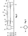
Die Vorrichtung
Die Vorrichtung
Die Betätigungseinheit
Die Anzahl der Drehungen und die Größe des Drehwinkels kann auf einer Eingabeeinheit
Die beiden zylindrischen Körper
Wenn die Schlauchenden an den zylindrischen Körpern
Mit dem mehrfach tordierten Schlauch
Zur Ermittlung eines optimalen Auslenkwinkels wurde ein Gitter auf den Unterarm einer Versuchsperson aufgezeichnet, wobei der Unterarm mit der Handfläche nach oben weisend auflag, was einem Drehwinkel von 0° entspricht. Anschließend wurde das Gitter vermessen, als der Unterarm um 180° verdreht war, wobei die Handfläche nach unten wies. Es zeigte sich eine Verformung der orthogonal zueinander verlaufenden Linien. Diese Verformung der Gitterlinien wurde durch eine Torsion des Schlauchs, auf den das gleiche Gitter mit den gleichen Abmessungen aufgezeichnet wurde, nachempfunden, in dem der Schlauch mit der Vorrichtung um einen bestimmten Torsionswinkel tordiert wurde. Es zeigte sich eine optimale Übereinstimmung der Gitterlinien auf dem Unterarm des Patienten und dem Schlauch bei einem Torsionswinkel von 120°.To determine an optimal deflection angle, a grid was recorded on the forearm of a subject with the forearm resting with the palm facing up, which corresponds to an angle of rotation of 0 °. The grid was then measured when the forearm was twisted 180 ° with the palm facing down. It showed a deformation of the orthogonal lines. This deformation of the grid lines was simulated by a twist of the tubing on which the same grid of the same dimensions was recorded, by twisting the tubing with the device by a certain torsion angle. It showed an optimal match of the grid lines on the forearm of the patient and the tube at a torsion angle of 120 °.
Darüber hinaus weist die Vorrichtung eine Messeinheit
Das oben beschriebene Verfahren zur Herstellung von gewebten Feuchtigkeitssensoren gehört mit Ausnahme der erfindungsgemäßen Prüfung der Feuchtigkeitssensoren zum Stand der Technik. Dieses Verfahren ist im Einzelnen in der
Nachfolgend wird die Überprüfung der Feuchtigkeitssensoren mit dem erfindungsgemäßen Prüfverfahren beschrieben. Das erfindungsgemäße Prüfverfahren sieht eine Endkontrolle (EK) während der laufenden Produktion in dem Prozessschritt II vor. Einer Charge von produzierten Feuchtigkeitssensoren werden für eine Stichprobe ein oder mehrere Sensoren
Die elektrischen Eigenschaften des Feuchtigkeitssensors
Die erfindungsgemäße Vorrichtung erlaubt eine Erfassung der Messwerte vor und/oder während und/oder nach einer oder mehreren Torsionen: Mit Messungen vor den Torsionen lassen sich auch entsprechende Vergleichswerte für eine vorzugsweise statistische Auswertung ermitteln.The device according to the invention permits detection of the measured values before and / or during and / or after one or more torsions: Measurements before the torsions can also be used to determine corresponding comparison values for a preferably statistical evaluation.
ZITATE ENTHALTEN IN DER BESCHREIBUNG QUOTES INCLUDE IN THE DESCRIPTION
Diese Liste der vom Anmelder aufgeführten Dokumente wurde automatisiert erzeugt und ist ausschließlich zur besseren Information des Lesers aufgenommen. Die Liste ist nicht Bestandteil der deutschen Patent- bzw. Gebrauchsmusteranmeldung. Das DPMA übernimmt keinerlei Haftung für etwaige Fehler oder Auslassungen.This list of the documents listed by the applicant has been generated automatically and is included solely for the better information of the reader. The list is not part of the German patent or utility model application. The DPMA assumes no liability for any errors or omissions.
Zitierte PatentliteraturCited patent literature
- WO 2011/116943 [0002, 0035, 0047] WO 2011/116943 [0002, 0035, 0047]
- WO 2010/091852 [0003] WO 2010/091852 [0003]
Claims (17)
Priority Applications (4)
| Application Number | Priority Date | Filing Date | Title |
|---|---|---|---|
| DE102012017205.2A DE102012017205A1 (en) | 2012-08-31 | 2012-08-31 | Method and device for testing sensors to be applied to the skin of a patient for the detection of fluid or moisture |
| EP13753582.9A EP2890422B1 (en) | 2012-08-31 | 2013-08-19 | Method and device for examining sensors to be applied to the skin of a patient for detecting fluids or moisture |
| PCT/EP2013/002486 WO2014032778A1 (en) | 2012-08-31 | 2013-08-19 | Method and device for examining sensors to be applied to the skin of a patient for detecting fluids or moisture |
| US14/012,326 US9645218B2 (en) | 2012-08-31 | 2013-08-28 | Method and device for testing sensors to be applied on a patient's skin for the detection of fluid or moisture |
Applications Claiming Priority (1)
| Application Number | Priority Date | Filing Date | Title |
|---|---|---|---|
| DE102012017205.2A DE102012017205A1 (en) | 2012-08-31 | 2012-08-31 | Method and device for testing sensors to be applied to the skin of a patient for the detection of fluid or moisture |
Publications (1)
| Publication Number | Publication Date |
|---|---|
| DE102012017205A1 true DE102012017205A1 (en) | 2014-03-27 |
Family
ID=50182548
Family Applications (1)
| Application Number | Title | Priority Date | Filing Date |
|---|---|---|---|
| DE102012017205.2A Withdrawn DE102012017205A1 (en) | 2012-08-31 | 2012-08-31 | Method and device for testing sensors to be applied to the skin of a patient for the detection of fluid or moisture |
Country Status (4)
| Country | Link |
|---|---|
| US (1) | US9645218B2 (en) |
| EP (1) | EP2890422B1 (en) |
| DE (1) | DE102012017205A1 (en) |
| WO (1) | WO2014032778A1 (en) |
Families Citing this family (7)
| Publication number | Priority date | Publication date | Assignee | Title |
|---|---|---|---|---|
| DE102015003254A1 (en) * | 2015-03-16 | 2016-09-22 | Fresenius Medical Care Deutschland Gmbh | Textile fabric for application to the skin and / or a wound of a patient and transdermal patch and arrangement of a transdermal patch and an evaluation unit |
| CN109715114A (en) * | 2016-07-22 | 2019-05-03 | 易希提卫生与保健公司 | Sensing device and charging system |
| JP2019208979A (en) * | 2018-06-07 | 2019-12-12 | 日本電信電話株式会社 | Element density measurement device |
| CN109145787A (en) * | 2018-08-07 | 2019-01-04 | 深圳市汇顶科技股份有限公司 | Detect the method, apparatus and terminal of moisture of skin |
| US10759441B1 (en) | 2019-05-06 | 2020-09-01 | Cambridge Mobile Telematics Inc. | Determining, scoring, and reporting mobile phone distraction of a driver |
| US10672249B1 (en) * | 2019-05-06 | 2020-06-02 | Cambridge Mobile Telematics Inc. | Determining, scoring, and reporting mobile phone distraction of a driver |
| US11788918B2 (en) | 2020-06-18 | 2023-10-17 | Trevillyan Labs, Llc | Fluid detection fabric |
Citations (4)
| Publication number | Priority date | Publication date | Assignee | Title |
|---|---|---|---|---|
| US5948994A (en) * | 1998-04-02 | 1999-09-07 | Jen; Ming-Hwa R. | Multi-functional test machine |
| DE102007006274A1 (en) * | 2007-02-08 | 2008-08-14 | Polyic Gmbh & Co. Kg | Measuring device with a measuring wheel |
| WO2010091852A1 (en) | 2009-02-14 | 2010-08-19 | Fresenius Medical Care Deutschland Gmbh | Apparatus for detecting moisture for an apparatus for monitoring the access to a patient, in particular for monitoring the vascular access during extracorporeal blood treatment |
| WO2011116943A1 (en) | 2010-03-23 | 2011-09-29 | Fresenius Medical Care Deutschland Gmbh | Moisture detection device for use with a device for monitoring an access to a patient |
Family Cites Families (10)
| Publication number | Priority date | Publication date | Assignee | Title |
|---|---|---|---|---|
| JPS6157847A (en) * | 1984-08-29 | 1986-03-24 | Sharp Corp | Field effect type humidity sensor |
| US5036859A (en) * | 1988-07-26 | 1991-08-06 | Travis International, Inc. | Moisture detector and indicator |
| US6461329B1 (en) * | 2000-03-13 | 2002-10-08 | Medtronic Minimed, Inc. | Infusion site leak detection system and method of using the same |
| US7147615B2 (en) * | 2001-06-22 | 2006-12-12 | Baxter International Inc. | Needle dislodgement detection |
| US7218237B2 (en) * | 2004-05-27 | 2007-05-15 | Lawrence Kates | Method and apparatus for detecting water leaks |
| WO2006008866A1 (en) * | 2004-07-16 | 2006-01-26 | Kabushiki Kaisha Awajitec | Moisture sensor |
| EP1881322B8 (en) * | 2006-07-18 | 2011-09-28 | Roche Diagnostics GmbH | Space-optimised portable measuring system |
| US7605710B2 (en) * | 2006-08-18 | 2009-10-20 | Fresenius Medical Care Holdings, Inc. | Wetness sensor |
| WO2011050382A2 (en) * | 2009-10-30 | 2011-05-05 | Peter Hagl | Sensor device |
| US9655787B2 (en) * | 2010-11-19 | 2017-05-23 | Covenant Ministries Of Benevolence | Stacked moisture sensing device |
-
2012
- 2012-08-31 DE DE102012017205.2A patent/DE102012017205A1/en not_active Withdrawn
-
2013
- 2013-08-19 WO PCT/EP2013/002486 patent/WO2014032778A1/en not_active Ceased
- 2013-08-19 EP EP13753582.9A patent/EP2890422B1/en not_active Not-in-force
- 2013-08-28 US US14/012,326 patent/US9645218B2/en not_active Expired - Fee Related
Patent Citations (4)
| Publication number | Priority date | Publication date | Assignee | Title |
|---|---|---|---|---|
| US5948994A (en) * | 1998-04-02 | 1999-09-07 | Jen; Ming-Hwa R. | Multi-functional test machine |
| DE102007006274A1 (en) * | 2007-02-08 | 2008-08-14 | Polyic Gmbh & Co. Kg | Measuring device with a measuring wheel |
| WO2010091852A1 (en) | 2009-02-14 | 2010-08-19 | Fresenius Medical Care Deutschland Gmbh | Apparatus for detecting moisture for an apparatus for monitoring the access to a patient, in particular for monitoring the vascular access during extracorporeal blood treatment |
| WO2011116943A1 (en) | 2010-03-23 | 2011-09-29 | Fresenius Medical Care Deutschland Gmbh | Moisture detection device for use with a device for monitoring an access to a patient |
Non-Patent Citations (2)
| Title |
|---|
| www.muehlbauer.sk_1 * |
| www.muehlbauer.sk_2 * |
Also Published As
| Publication number | Publication date |
|---|---|
| EP2890422B1 (en) | 2016-10-05 |
| WO2014032778A1 (en) | 2014-03-06 |
| EP2890422A1 (en) | 2015-07-08 |
| US9645218B2 (en) | 2017-05-09 |
| US20140059837A1 (en) | 2014-03-06 |
Similar Documents
| Publication | Publication Date | Title |
|---|---|---|
| EP2890422B1 (en) | Method and device for examining sensors to be applied to the skin of a patient for detecting fluids or moisture | |
| DE102015003254A1 (en) | Textile fabric for application to the skin and / or a wound of a patient and transdermal patch and arrangement of a transdermal patch and an evaluation unit | |
| EP2836246B1 (en) | Apparatus and method for monitoring vascular access of a patient comprising a woven moisture sensor with a control portion | |
| WO2016029985A1 (en) | Biaxial measuring device and method for determining normal and shear stress-correlated material parameters | |
| DE102009000501A1 (en) | Degradation and integrity measuring device for absorbable metal implants | |
| WO2015185227A1 (en) | Receptacle device for electrical impedance analysis | |
| DE102012112147A1 (en) | Device for detecting leaks in a fluid line, in particular a high-pressure fluid line | |
| DE2848073C2 (en) | ||
| DE19946458C2 (en) | Device and method for characterizing spheroids | |
| EP2545541B1 (en) | Mri training device | |
| DE102008042554A1 (en) | Portable monitoring device for monitoring respiration of patient suffering from e.g. sleep apnea, has elastically deformable electrodes arranged adjacent to insulation layer made of dielectric elastomer material | |
| EP2523007A2 (en) | Method of testing and producing of an electric circuit | |
| AT507293B1 (en) | PRESSURE INDICATOR FOR MEDICAL PRINCIPLES | |
| DE10252211A1 (en) | Viscoelastic foam testing device for determination of foam pressure and deformation behavior, whereby a light rigid plate is used to compress the foam by a given amount for a given period, before the foam is suddenly released | |
| DE102012018124B4 (en) | Isometric Finger Gripper Target Measuring Device | |
| DE102011081713A1 (en) | Verdrahtungsprüfeinrichtung | |
| EP3847466A1 (en) | Method for positioning test substrate, probes and inspection unit relative to one another, and tester for carrying out the method | |
| DE102008062447B3 (en) | Flexible layer structure for the acquisition of mechanical parameters and methods for their adaptive behavior | |
| DE102017109398A1 (en) | METHOD AND DEVICE FOR MONITORING A CONNECTION BETWEEN ELECTRICAL EQUIPMENT | |
| DE102015210638A1 (en) | Method and device for determining a voluntary movement of a limb | |
| DE102005029414B4 (en) | Method for determining the degree of digestion of biological cells by electroporation | |
| DE2344544C2 (en) | Procedure for testing spring slats | |
| DE102009014554A1 (en) | Method and test device for the identification of test samples and multifunctional test samples | |
| EP1235513B1 (en) | Diagnostic device | |
| DE102022209907A1 (en) | Wearable device for detecting stenosis and system therewith |
Legal Events
| Date | Code | Title | Description |
|---|---|---|---|
| R012 | Request for examination validly filed | ||
| R016 | Response to examination communication | ||
| R119 | Application deemed withdrawn, or ip right lapsed, due to non-payment of renewal fee |