DE102011116685A1 - Peilkorrekturverfahren - Google Patents
Peilkorrekturverfahren Download PDFInfo
- Publication number
- DE102011116685A1 DE102011116685A1 DE201110116685 DE102011116685A DE102011116685A1 DE 102011116685 A1 DE102011116685 A1 DE 102011116685A1 DE 201110116685 DE201110116685 DE 201110116685 DE 102011116685 A DE102011116685 A DE 102011116685A DE 102011116685 A1 DE102011116685 A1 DE 102011116685A1
- Authority
- DE
- Germany
- Prior art keywords
- ais
- bearing
- signal
- platform
- transponder signal
- Prior art date
- Legal status (The legal status is an assumption and is not a legal conclusion. Google has not performed a legal analysis and makes no representation as to the accuracy of the status listed.)
- Withdrawn
Links
- 238000000034 method Methods 0.000 claims abstract description 22
- 238000012937 correction Methods 0.000 claims abstract description 16
- 230000007613 environmental effect Effects 0.000 description 7
- 238000005259 measurement Methods 0.000 description 3
- 238000005352 clarification Methods 0.000 description 1
- 230000001419 dependent effect Effects 0.000 description 1
- 230000008030 elimination Effects 0.000 description 1
- 238000003379 elimination reaction Methods 0.000 description 1
- 238000011156 evaluation Methods 0.000 description 1
- 230000002349 favourable effect Effects 0.000 description 1
- 238000001914 filtration Methods 0.000 description 1
- 238000012544 monitoring process Methods 0.000 description 1
- 230000008520 organization Effects 0.000 description 1
- 230000009897 systematic effect Effects 0.000 description 1
Images

Classifications
-
- G—PHYSICS
- G08—SIGNALLING
- G08G—TRAFFIC CONTROL SYSTEMS
- G08G3/00—Traffic control systems for marine craft
-
- G—PHYSICS
- G01—MEASURING; TESTING
- G01S—RADIO DIRECTION-FINDING; RADIO NAVIGATION; DETERMINING DISTANCE OR VELOCITY BY USE OF RADIO WAVES; LOCATING OR PRESENCE-DETECTING BY USE OF THE REFLECTION OR RERADIATION OF RADIO WAVES; ANALOGOUS ARRANGEMENTS USING OTHER WAVES
- G01S1/00—Beacons or beacon systems transmitting signals having a characteristic or characteristics capable of being detected by non-directional receivers and defining directions, positions, or position lines fixed relatively to the beacon transmitters; Receivers co-operating therewith
- G01S1/02—Beacons or beacon systems transmitting signals having a characteristic or characteristics capable of being detected by non-directional receivers and defining directions, positions, or position lines fixed relatively to the beacon transmitters; Receivers co-operating therewith using radio waves
- G01S1/68—Marker, boundary, call-sign, or like beacons transmitting signals not carrying directional information
-
- G—PHYSICS
- G01—MEASURING; TESTING
- G01S—RADIO DIRECTION-FINDING; RADIO NAVIGATION; DETERMINING DISTANCE OR VELOCITY BY USE OF RADIO WAVES; LOCATING OR PRESENCE-DETECTING BY USE OF THE REFLECTION OR RERADIATION OF RADIO WAVES; ANALOGOUS ARRANGEMENTS USING OTHER WAVES
- G01S13/00—Systems using the reflection or reradiation of radio waves, e.g. radar systems; Analogous systems using reflection or reradiation of waves whose nature or wavelength is irrelevant or unspecified
- G01S13/74—Systems using reradiation of radio waves, e.g. secondary radar systems; Analogous systems
- G01S13/76—Systems using reradiation of radio waves, e.g. secondary radar systems; Analogous systems wherein pulse-type signals are transmitted
- G01S13/765—Systems using reradiation of radio waves, e.g. secondary radar systems; Analogous systems wherein pulse-type signals are transmitted with exchange of information between interrogator and responder
-
- G—PHYSICS
- G01—MEASURING; TESTING
- G01S—RADIO DIRECTION-FINDING; RADIO NAVIGATION; DETERMINING DISTANCE OR VELOCITY BY USE OF RADIO WAVES; LOCATING OR PRESENCE-DETECTING BY USE OF THE REFLECTION OR RERADIATION OF RADIO WAVES; ANALOGOUS ARRANGEMENTS USING OTHER WAVES
- G01S3/00—Direction-finders for determining the direction from which infrasonic, sonic, ultrasonic, or electromagnetic waves, or particle emission, not having a directional significance, are being received
- G01S3/02—Direction-finders for determining the direction from which infrasonic, sonic, ultrasonic, or electromagnetic waves, or particle emission, not having a directional significance, are being received using radio waves
- G01S3/023—Monitoring or calibrating
-
- G—PHYSICS
- G01—MEASURING; TESTING
- G01S—RADIO DIRECTION-FINDING; RADIO NAVIGATION; DETERMINING DISTANCE OR VELOCITY BY USE OF RADIO WAVES; LOCATING OR PRESENCE-DETECTING BY USE OF THE REFLECTION OR RERADIATION OF RADIO WAVES; ANALOGOUS ARRANGEMENTS USING OTHER WAVES
- G01S5/00—Position-fixing by co-ordinating two or more direction or position line determinations; Position-fixing by co-ordinating two or more distance determinations
- G01S5/0009—Transmission of position information to remote stations
- G01S5/0072—Transmission between mobile stations, e.g. anti-collision systems
-
- G—PHYSICS
- G01—MEASURING; TESTING
- G01S—RADIO DIRECTION-FINDING; RADIO NAVIGATION; DETERMINING DISTANCE OR VELOCITY BY USE OF RADIO WAVES; LOCATING OR PRESENCE-DETECTING BY USE OF THE REFLECTION OR RERADIATION OF RADIO WAVES; ANALOGOUS ARRANGEMENTS USING OTHER WAVES
- G01S5/00—Position-fixing by co-ordinating two or more direction or position line determinations; Position-fixing by co-ordinating two or more distance determinations
- G01S5/02—Position-fixing by co-ordinating two or more direction or position line determinations; Position-fixing by co-ordinating two or more distance determinations using radio waves
- G01S5/08—Position of single direction-finder fixed by determining direction of a plurality of spaced sources of known location
Landscapes
- Engineering & Computer Science (AREA)
- Radar, Positioning & Navigation (AREA)
- Remote Sensing (AREA)
- Physics & Mathematics (AREA)
- General Physics & Mathematics (AREA)
- Computer Networks & Wireless Communication (AREA)
- Ocean & Marine Engineering (AREA)
- Radar Systems Or Details Thereof (AREA)
Abstract
Die Erfindung betrifft ein Peilkorrekturverfahren für Peilsysteme mit folgenden Verfahrensschritten: – das AIS-Transpondersignal einer Plattform (S1, S2) wird empfangen und isoliert, wobei Signalanteile die nicht zu dem betrachteten Signal gehören unter Ausnutzung der Kenntnis der Signalstruktur des AIS-Transpondersignals ausgefiltert werden; – mit dem derart isolierten Transpondersignal wird eine Peilung durchgeführt; – das gewonnene Peilergebnis wird mit der Richtung verglichen, die sich aus der im AIS-Transpondersignal enthaltenen Positions-Meldung der Plattform (S1, S2) ergibt; – es wird eine Plausibilitätsprüfung durchgeführt, ob das Peilergebnis mit der im AIS-Transpondersignal enthaltenen Positions-Meldung vereinbar ist; – aus plausiblen Abweichungen zwischen dem Peilergebnis und der sich aus der Positions-Meldung ergebenden Richtung der Plattform (S1, S2) werden Korrekturwerte für die Peilung bestimmt.The invention relates to a bearing correction method for direction finding systems with the following method steps: the AIS transponder signal of a platform (S1, S2) is received and isolated, whereby signal portions which do not belong to the signal under consideration are filtered out using the knowledge of the signal structure of the AIS transponder signal; Figs; a bearing is performed with the transponder signal thus isolated; Figs; the obtained bearing result is compared with the direction resulting from the position message of the platform (S1, S2) contained in the AIS transponder signal; Figs; a plausibility check is carried out as to whether the bearing result is compatible with the position message contained in the AIS transponder signal; Figs; From plausible deviations between the bearing result and the direction of the platform (S1, S2) resulting from the position message, correction values for the bearing are determined.
Description
Die Erfindung betrifft ein Peilkorrekturverfahren zur Korrektur eines insbesondere luftfahrzeuggestützten Peilersystems. Das Peilersystem kann z. B. auf einem bemannten oder unbemannten Luftfahrzeug angeordnet sein, z. B. auf einem global operierenden UAV (unmanned aerial vehicle) zur Signalaufklärung. Darüber hinaus kann es sich aber auch um ein stationäres, landgestütztes Peilersystem handeln, z. B. zur Hafenüberwachung.The invention relates to a Peilkorrekturverfahren for correcting a particular aircraft-based Peilersystems. The Peilersystem can z. B. be arranged on a manned or unmanned aerial vehicle, for. On a globally operating UAV (unmanned aerial vehicle) for signal clarification. In addition, it may also be a stationary, land-based Peilersystem, z. B. for port monitoring.
Bei bekannten Peilkorrekturverfahren werden im Vorfeld der Anwendung Korrekturwerte zur Peilung aufgenommen und in einer Korrekturtabelle abgelegt. Bei diesen im Vorfeld aufgenommenen Werten können die im Einsatz auftretenden Umwelteinflüsse nicht berücksichtigt werden.In the case of known bearing correction methods, correction values for the bearing are recorded in advance of the application and stored in a correction table. In the case of these values recorded in advance, the environmental influences occurring in the field can not be taken into account.
Prinzipiell können jedoch Messungenauigkeiten in der Regel auch durch Kalibrierung nicht vollständig beseitigt werden, da sie unter anderem auch von Umweltbedingungen wie z. B. inhomogenes Vereisen eines Radoms oder atmosphärischen Bedingungen, abhängig sein können.In principle, however, measurement inaccuracies can generally not be completely eliminated by calibration, as they are also affected by environmental conditions such as environmental factors. B. inhomogeneous icing of a radome or atmospheric conditions may be dependent.
Um die Sicherheit und Lenkung des internationalen Schiffsverkehrs zu verbessern, wird seit einigen Jahren ein Funksystem unter der Bezeichnung AIS (Automatic Identification System) eingesetzt, das von der Internationalen Seeschifffahrts-Organisation als verbindlicher Standard angenommen wurde. Dabei sind Schiffe mit weitreichenden Transpondern ausgestattet, die schiffsspezifische Daten aussenden, darunter auch dynamische Schiffsdaten wie Schiffsposition, Vorausrichtung, Geschwindigkeit etc. AIS-Signale werden darüber hinaus auch von stationären Plattformen, insbesondere Leuchttürmen ausgesandt.In order to improve the safety and management of international shipping, a radio system called the Automatic Identification System (AIS) has been in use for some years and has been adopted by the International Maritime Organization as a binding standard. These ships are equipped with long-range transponders that send ship-specific data, including dynamic ship data such as ship position, pre-alignment, speed, etc. AIS signals are also sent from stationary platforms, especially lighthouses.
Der Erfindung liegt die Aufgabe zugrunde, ein Peilkorrekturverfahren anzugeben, das mit hoher Zuverlässigkeit während des Einsatzes durchgeführt werden kann.The invention has for its object to provide a Peilkorrekturverfahren that can be performed with high reliability during use.
Diese Aufgabe wird mit dem Verfahren nach Anspruch 1 gelöst. Vorteilhafte Ausführungen sowie ein Aufklärungsverfahren, das die Ergebnisse des erfindungsgemäßen Verfahrens nutzt, sind Gegenstände weiterer Ansprüche.This object is achieved by the method according to claim 1. Advantageous embodiments as well as a reconnaissance method which utilizes the results of the method according to the invention are objects of further claims.
Mit dem erfindungsgemäßen Verfahren können Messungenauigkeiten der Peilung während des Einsatzes flexibel unter den herrschenden Einsatzbedingungen ausgeglichen werden.With the method according to the invention measurement inaccuracies of the bearing during use can be compensated flexibly under the prevailing conditions of use.
Die Erfindung führt insbesondere bei bewegten Peilsystemen, die naturgemäß extremen Umwelteinflüssen ausgesetzt sind, zu einer erheblichen Verbesserung der Leistungsfähigkeit des Peilsystems.The invention leads to a considerable improvement in the performance of the direction finding system, especially in the case of moving direction finding systems, which are naturally exposed to extreme environmental influences.
Das erfindungsgemäße Verfahren nutzt das standardisierte, beliebig verfügbare AIS-Transpondersignal von insbesondere schwimmender oder stationärer Plattformen, welche ihre Eigenposition fortlaufend melden, zur Durchführung der Peilerkorrektur. Die Transpondersignale haben eine charakteristische Struktur und können daher auf einfache Weise identifiziert und von dem sonstigen Signalhintergrund isoliert werden.The method according to the invention uses the standardized, freely available AIS transponder signal, in particular from floating or stationary platforms, which continuously report their own position in order to carry out the correction of the bearing. The transponder signals have a characteristic structure and can therefore be easily identified and isolated from the other signal background.
Gemäß der Erfindung werden zunächst AIS-Transpondersignale gleichzeitig in allen Antennensegmenten des Peilersystems isoliert. Isoliert heißt hierbei, alle Beiträge des empfangenen Signals wegzufiltern, die nicht zum betrachteten AIS-Signal gehören. Bei dieser Filterung wird ausgenutzt, dass Struktur und Inhalt des AIS-Signals detailliert bekannt ist. Mit den isolierten Signalen werden dann unter Verwendung herkömmlicher Peilverfahren Peilungen durchgeführt. Hinsichtlich der zu verwendenden Peilverfahren bestehen keine Einschränkungen. Anschließend werden die derart ermittelten Peilwerte mit den Richtungen der betreffenden AIS-Plattform, welche sich aus den im AIS-Signal enthaltenen Positionsdaten ergeben, verglichen.According to the invention, first AIS transponder signals are simultaneously isolated in all antenna segments of the direction finder system. Isolated means to filter out all contributions of the received signal that do not belong to the considered AIS signal. This filtering makes use of the fact that the structure and content of the AIS signal is known in detail. Bearing is then performed with the isolated signals using conventional direction finding techniques. There are no restrictions with regard to the bearing methods to be used. Subsequently, the bearing values thus determined are compared with the directions of the relevant AIS platform, which result from the position data contained in the AIS signal.
Kann nach Durchführung einer Plausibilitätsprüfung davon ausgegangen werden, dass die gesendete AIS-Position zu der Peilung gehört, wird entsprechend der geometrischen Richtung der gesendeten AIS-Position ein Korrekturwert für die Peilung berechnet.If, after carrying out a plausibility check, it can be assumed that the transmitted AIS position belongs to the bearing, a correction value for the bearing is calculated according to the geometric direction of the transmitted AIS position.
Die Plausibilitätsprüfung ist insbesondere in Fällen von Bedeutung, in denen zu viele AIS-Sendungen gleichzeitig aus einer Richtung kommen oder wenn die AIS-Plattform absichtlich oder versehentlich falsche Positionen meldet.The plausibility check is particularly important in cases where too many AIS shipments come from one direction at the same time or when the AIS platform intentionally or accidentally reports incorrect positions.
Die Plausibilitätsprüfung der empfangenen AIS-Information auf Zugehörigkeit zur Peilung erfolgt z. B. durch Einbeziehung der Peilungenauigkeit des Peilsystems. Liegt die empfangene AIS-Position im Vergleich zu dem Ergebnis der durchgeführten Peilung auch bei Durchführung mehrerer Peilungen systematisch außerhalb der zulässigen Grenzen der Messungenauigkeit, kann von einer gefälschten AIS-Information ausgegangen werden. Diese AIS-Information kann somit nicht zur Peilerkorrektur verwendet werden.The plausibility check of the received AIS information to belong to the bearing is z. B. by incorporating the bearing inaccuracy of the bearing system. If the received AIS position is systematically out of range compared to the result of the bearing finding, even if several bearings are executed the permissible limits of the measurement inaccuracy, can be assumed by a forged AIS information. This AIS information can thus not be used for direction correction.
Im Falle von Mehrdeutigkeiten, wenn z. B. mehrere AIS-Positionen oder mehrere Peilungen außerhalb der zulässigen Grenzen der Peilungenauigkeit liegen, können diese Mehrdeutigkeiten durch eine angemessene Zahl von Wiederholungen der Peilung unter deutlichen Richtungsänderungen vom Peiler zum Sender aufgelöst werden.In case of ambiguity, if z. For example, if multiple AIS positions or multiple bearings are outside the allowable limits of bearing uncertainty, these ambiguities may be resolved by an appropriate number of bearing repeats with significant direction changes from the direction finder to the transmitter.
Die mit dem erfindungsgemäßen Verfahren ermittelten Korrekturwerte gelten grundsätzlich nur für den Frequenzbereich des verwendeten AIS-Signals sowie für die entsprechende Empfangsrichtung. Um das Peilersystem bezüglich weiterer Richtungen zu kalibrieren, können AIS-Signale aus anderen Blickrichtungen des Peilersystems herangezogen werden. Alternativ ist es möglich, das Verfahren mit einer geänderten Ausrichtung des Peilersystems durchzuführen, was z. B. bei einem luftfahrzeuggestützten Peilersystem leicht durchführbar ist. Durch entsprechende relative Bewegung des fliegenden Trägers bezüglich der verfügbaren AIS-Sender ergeben sich sukzessive Korrekturwerte über den gesamten Azimut- und Elevationsbereich. Die Korrekturwerte können kontinuierlich verfeinert und verifiziert werden. Sie passen sich zudem automatisch an langsam veränderliche Umweltbedingungen an.The correction values determined using the method according to the invention basically apply only to the frequency range of the AIS signal used and to the corresponding receive direction. In order to calibrate the direction finder system with regard to further directions, AIS signals from other directions of the direction finder system can be used. Alternatively, it is possible to carry out the method with a changed orientation of the Peilersystems what z. B. in an aircraft-based Peilersystem easily feasible. Corresponding relative movement of the flying carrier with respect to the available AIS transmitters results in successive correction values over the entire azimuth and elevation range. The correction values can be continuously refined and verified. They also adapt automatically to slowly changing environmental conditions.
In weiteren Auswerteschritten können weitere Sender auf der AIS-Plattform genutzt werden, um Korrekturwerte für weitere Frequenzbereiche zu erhalten. Hierbei wird ausgenutzt, dass insbesondere schwimmende AIS-Plattformen (Schiffe) in der Regel neben dem AIS-Transponder weitere aktive Funksender auf anderen Frequenzbändern aufweist. Das Verfahren zur Ermittlung der Korrekturwerte für die betreffenden Frequenzbänder ist dasselbe wie bei der Peilung des AIS-Transpondersignals, wobei die aus dem AIS-Transpondersignal bereits bekannte Position der AIS-Plattform verwendet wird.In further evaluation steps, additional transmitters can be used on the AIS platform to obtain correction values for additional frequency ranges. This exploits the fact that, in particular, floating AIS platforms (ships) generally have, in addition to the AIS transponder, further active radio transmitters on other frequency bands. The procedure for determining the correction values for the respective frequency bands is the same as for the AIS transponder signal bearing, using the position of the AIS platform already known from the AIS transponder signal.
In einer bevorzugten Ausführung ist das Peilersystem Teil eines Aufklärungssystems, das weitere Aufklärungssensoren an Bord hat. Die sich aus der Durchführung des erfindungsgemäßen Verfahrens ergebende Zuordnung von Emissionen (AIS-Transpondersignale oder die Signale weiterer Emitter der AIS-Plattform) stellen Informationen dar, die in die Ermittlung der Aufklärungslage eingehen können.In a preferred embodiment, the direction finder system is part of a reconnaissance system that has additional reconnaissance sensors on board. The assignment of emissions (AIS transponder signals or the signals of further emitters of the AIS platform) resulting from the implementation of the method according to the invention represents information that can go into the determination of the reconnaissance situation.
Vorteile, die durch die Erfindung erzielt werden:
- • Erhöhung der Peilgenauigkeit,
- • Eliminierung von systematischen umweltabhängigen Peilfehlern,
- • Reduktion von Umwelteinflüssen auf die Leistungsfähigkeit des Peilsystems,
- • Erkennen von falschen AIS-Informationen,
- • Erkennen von schwimmenden Plattformen,
- • Verbesserung der Aufklärungslage.
- • increase the DF accuracy,
- • Elimination of systematic environmental bearing errors,
- • Reduction of environmental influences on the performance of the bearing system,
- • detecting false AIS information,
- • detecting floating platforms,
- • Improvement of the educational situation.
Die Erfindung wird anhand eines Ausführungsbeispiels unter Bezugnahme auf eine Fig. näher beschrieben. Sie zeigt in schematischer Darstellung das Vorgehen bei der Auflösung von Mehrdeutigkeiten bei der Zuordnung von empfangenen Signalen zu AIS-Plattformen.The invention will be described with reference to an embodiment with reference to a Fig. Closer. It shows a schematic representation of the procedure for the resolution of ambiguities in the assignment of received signals to AIS platforms.
Man erkennt zwei schwimmende AIS-Plattformen S1 und S2, deren Signale das luftgestützte Peilersystem zeitlich hintereinander in zwei Positionen P1, P2 detektiert.One recognizes two floating AIS platforms S1 and S2, whose signals detect the airborne direction finding system in succession in two positions P1, P2.
Die Bedeutung der einzelnen Signale ist wie folgt: 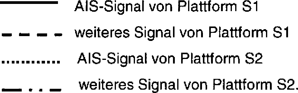
In Position P1 des Peilersystems werden die beiden AIS-Signale der Plattformen S1, S2 in fast der selben Richtung detektiert. Die weiteren Emissionen der Plattformen können in den Peilerposition P1 nicht eindeutig einer der beiden Plattformen zugeordnet werden.In position P1 of the direction finding system, the two AIS signals of the platforms S1, S2 are detected in almost the same direction. The further emissions of the platforms can not be unambiguously assigned to one of the two platforms in the direction finder position P1.
Die Peilungen werden deshalb in Sensorposition P2 wiederholt. Von dort aus können nun alle Signale, die dem Peilersystem anhand ihrer AIS-Signatur bzw. ihrer Signalstruktur bekannt sind, erneut detektiert werden. Wegen der an Position P2 günstigeren Geometrie kann dann sowohl die Korrektheit der gemeldeten AIS-Positionen der Plattformen S1 und S2 sowie die Signalzuordnung der weiteren Signale zu den Plattformen S1 bzw. S2 nachgewiesen werden.The bearings are therefore repeated in sensor position P2. From there, all signals that are known to the direction finding system based on their AIS signature or signal structure can now be detected again. Because of the more favorable geometry at position P2 then both the correctness of the reported AIS positions of the platforms S1 and S2 and the signal assignment of the further signals to the platforms S1 and S2 can be detected.
Claims (5)
Priority Applications (2)
| Application Number | Priority Date | Filing Date | Title |
|---|---|---|---|
| DE201110116685 DE102011116685A1 (en) | 2011-10-21 | 2011-10-21 | Peilkorrekturverfahren |
| EP12007234.3A EP2584374A1 (en) | 2011-10-21 | 2012-10-19 | method for correcting radio direction determination |
Applications Claiming Priority (1)
| Application Number | Priority Date | Filing Date | Title |
|---|---|---|---|
| DE201110116685 DE102011116685A1 (en) | 2011-10-21 | 2011-10-21 | Peilkorrekturverfahren |
Publications (1)
| Publication Number | Publication Date |
|---|---|
| DE102011116685A1 true DE102011116685A1 (en) | 2013-04-25 |
Family
ID=47594173
Family Applications (1)
| Application Number | Title | Priority Date | Filing Date |
|---|---|---|---|
| DE201110116685 Withdrawn DE102011116685A1 (en) | 2011-10-21 | 2011-10-21 | Peilkorrekturverfahren |
Country Status (2)
| Country | Link |
|---|---|
| EP (1) | EP2584374A1 (en) |
| DE (1) | DE102011116685A1 (en) |
Families Citing this family (2)
| Publication number | Priority date | Publication date | Assignee | Title |
|---|---|---|---|---|
| CN113965876B (en) * | 2021-09-14 | 2023-12-12 | 成都德辰博睿科技有限公司 | Method for realizing comprehensive test platform of monitoring system |
| CN115980678A (en) * | 2022-11-24 | 2023-04-18 | 桂林长海发展有限责任公司 | A method, device, equipment and medium for frequency and direction finding with flexible and large instantaneous bandwidth |
Citations (2)
| Publication number | Priority date | Publication date | Assignee | Title |
|---|---|---|---|---|
| US20090326816A1 (en) * | 2006-05-30 | 2009-12-31 | Choon Bae Park | Attitude correction apparatus and method for inertial navigation system using camera-type solar sensor |
| US20110163908A1 (en) * | 2008-06-18 | 2011-07-07 | Saab Ab | Validity check of vehicle position information |
Family Cites Families (6)
| Publication number | Priority date | Publication date | Assignee | Title |
|---|---|---|---|---|
| US7777675B2 (en) * | 1999-03-05 | 2010-08-17 | Era Systems Corporation | Deployable passive broadband aircraft tracking |
| US8798911B2 (en) * | 2004-07-12 | 2014-08-05 | L-3 Communications Corporation | Systems and methods for determining bearing |
| US7724178B2 (en) * | 2004-12-17 | 2010-05-25 | Honeywell International Inc. | Traffic alert collision avoidance system (TCAS) devices and methods |
| US20090027254A1 (en) * | 2007-02-16 | 2009-01-29 | James Roy Troxel | Method and apparatus to improve the ability to decode ads-b squitters through multiple processing paths |
| ES2438599T3 (en) * | 2008-06-18 | 2014-01-17 | Saab Ab | Validity check of position information of a vehicle transmitted through a time-synchronized data link |
| GB2478529B (en) * | 2010-03-08 | 2013-08-21 | Cantor Internat Ltd | Processing radio signals to minimise interference effects |
-
2011
- 2011-10-21 DE DE201110116685 patent/DE102011116685A1/en not_active Withdrawn
-
2012
- 2012-10-19 EP EP12007234.3A patent/EP2584374A1/en not_active Withdrawn
Patent Citations (2)
| Publication number | Priority date | Publication date | Assignee | Title |
|---|---|---|---|---|
| US20090326816A1 (en) * | 2006-05-30 | 2009-12-31 | Choon Bae Park | Attitude correction apparatus and method for inertial navigation system using camera-type solar sensor |
| US20110163908A1 (en) * | 2008-06-18 | 2011-07-07 | Saab Ab | Validity check of vehicle position information |
Also Published As
| Publication number | Publication date |
|---|---|
| EP2584374A1 (en) | 2013-04-24 |
Similar Documents
| Publication | Publication Date | Title |
|---|---|---|
| DE102017124756B4 (en) | RADAR CALIBRATION WITH KNOWN GLOBAL POSITIONING OF STATIC OBJECTS | |
| EP3891718B1 (en) | Device, method and computer program for handling speech radio signals | |
| DE102017130624A1 (en) | VEHICLE POSITION DETERMINATION SYSTEM USING V2X, SENSOR AND GNSS INFORMATION | |
| DE102015008403B3 (en) | Method for automatic classification of radar objects | |
| DE102014003152A1 (en) | Method and device for determining at least one object parameter of a means of transport | |
| EP2936205A2 (en) | Method for providing a gnss signal | |
| DE3835992A1 (en) | COLLISION PREVENTION SYSTEM | |
| DE112020003536T5 (en) | Method and device for detecting a deception process of a GNSS system | |
| DE102012224110A1 (en) | Method for determining position data of objects e.g. vehicle and traffic light, on road, involves filtering data of vehicle based on detected distance between vehicle and another vehicle for determining data of latter vehicle on road | |
| EP3374798B1 (en) | System for plausibilizing satellite signals of global navigation systems | |
| DE102011116685A1 (en) | Peilkorrekturverfahren | |
| DE102018209162A1 (en) | Safe method for determining the position of a receiving device | |
| DE102015119308A1 (en) | Method and apparatus for providing data for a satellite navigation-based automatic landing to an aircraft | |
| DE102010052474B4 (en) | Flight Guidance System | |
| DE102014101902A1 (en) | Monitoring system for monitoring and method for verifying a vessel or multiple vessels | |
| WO2011157723A1 (en) | System and method for collision avoidance | |
| DE102019218078B4 (en) | Determination of a situation in the environment of a motor vehicle | |
| DE102010052475A1 (en) | tracking system | |
| DE19818426C2 (en) | Remote reconnaissance and targeting procedures | |
| WO2012069179A1 (en) | Method and system for the georeferenced determination of the location of containers in the loading range of container cranes | |
| DE102010023755B4 (en) | Altitude determining device | |
| DE112019007912T5 (en) | object detection device | |
| DE102023120865B4 (en) | Position sensor for spatially resolved detection of objects in a surveillance area | |
| EP2251850A2 (en) | Device for determining the bearing of aircrafts | |
| DE102017117495A1 (en) | System and method for determining the position of a transmitting unit and watercraft with a system for determining the position of a transmitting unit |
Legal Events
| Date | Code | Title | Description |
|---|---|---|---|
| R012 | Request for examination validly filed | ||
| R016 | Response to examination communication | ||
| R082 | Change of representative |
Representative=s name: MEEL, THOMAS, DIPL.-PHYS., DE |
|
| R081 | Change of applicant/patentee |
Owner name: AIRBUS DEFENCE AND SPACE GMBH, DE Free format text: FORMER OWNER: EADS DEUTSCHLAND GMBH, 85521 OTTOBRUNN, DE Effective date: 20140916 |
|
| R082 | Change of representative |
Representative=s name: MEEL, THOMAS, DIPL.-PHYS., DE Effective date: 20140916 |
|
| R120 | Application withdrawn or ip right abandoned |