[go: up one dir, main page]

DE102011052846A1 - Dishwasher with controlled circulation of the lower spray arm - Google Patents

Dishwasher with controlled circulation of the lower spray arm Download PDF

Info

Publication number
DE102011052846A1
DE102011052846A1 DE102011052846A DE102011052846A DE102011052846A1 DE 102011052846 A1 DE102011052846 A1 DE 102011052846A1 DE 102011052846 A DE102011052846 A DE 102011052846A DE 102011052846 A DE102011052846 A DE 102011052846A DE 102011052846 A1 DE102011052846 A1 DE 102011052846A1
Authority
DE
Germany
Prior art keywords
rotation
spray
drive shaft
spraying device
drive
Prior art date
Legal status (The legal status is an assumption and is not a legal conclusion. Google has not performed a legal analysis and makes no representation as to the accuracy of the status listed.)
Granted
Application number
DE102011052846A
Other languages
German (de)
Other versions
DE102011052846B4 (en
Inventor
Jordan R. Fountain
Current Assignee (The listed assignees may be inaccurate. Google has not performed a legal analysis and makes no representation or warranty as to the accuracy of the list.)
Whirlpool Corp
Original Assignee
Whirlpool Corp
Priority date (The priority date is an assumption and is not a legal conclusion. Google has not performed a legal analysis and makes no representation as to the accuracy of the date listed.)
Filing date
Publication date
Application filed by Whirlpool Corp filed Critical Whirlpool Corp
Publication of DE102011052846A1 publication Critical patent/DE102011052846A1/en
Application granted granted Critical
Publication of DE102011052846B4 publication Critical patent/DE102011052846B4/en
Expired - Fee Related legal-status Critical Current
Anticipated expiration legal-status Critical

Links

Images

Classifications

    • AHUMAN NECESSITIES
    • A47FURNITURE; DOMESTIC ARTICLES OR APPLIANCES; COFFEE MILLS; SPICE MILLS; SUCTION CLEANERS IN GENERAL
    • A47LDOMESTIC WASHING OR CLEANING; SUCTION CLEANERS IN GENERAL
    • A47L15/00Washing or rinsing machines for crockery or tableware
    • A47L15/42Details
    • A47L15/4214Water supply, recirculation or discharge arrangements; Devices therefor
    • A47L15/4219Water recirculation
    • A47L15/4221Arrangements for redirection of washing water, e.g. water diverters to selectively supply the spray arms
    • AHUMAN NECESSITIES
    • A47FURNITURE; DOMESTIC ARTICLES OR APPLIANCES; COFFEE MILLS; SPICE MILLS; SUCTION CLEANERS IN GENERAL
    • A47LDOMESTIC WASHING OR CLEANING; SUCTION CLEANERS IN GENERAL
    • A47L15/00Washing or rinsing machines for crockery or tableware
    • A47L15/14Washing or rinsing machines for crockery or tableware with stationary crockery baskets and spraying devices within the cleaning chamber
    • A47L15/18Washing or rinsing machines for crockery or tableware with stationary crockery baskets and spraying devices within the cleaning chamber with movably-mounted spraying devices
    • A47L15/22Rotary spraying devices
    • AHUMAN NECESSITIES
    • A47FURNITURE; DOMESTIC ARTICLES OR APPLIANCES; COFFEE MILLS; SPICE MILLS; SUCTION CLEANERS IN GENERAL
    • A47LDOMESTIC WASHING OR CLEANING; SUCTION CLEANERS IN GENERAL
    • A47L15/00Washing or rinsing machines for crockery or tableware
    • A47L15/0018Controlling processes, i.e. processes to control the operation of the machine characterised by the purpose or target of the control
    • A47L15/0021Regulation of operational steps within the washing processes, e.g. optimisation or improvement of operational steps depending from the detergent nature or from the condition of the crockery
    • A47L15/0031Water discharge phases
    • AHUMAN NECESSITIES
    • A47FURNITURE; DOMESTIC ARTICLES OR APPLIANCES; COFFEE MILLS; SPICE MILLS; SUCTION CLEANERS IN GENERAL
    • A47LDOMESTIC WASHING OR CLEANING; SUCTION CLEANERS IN GENERAL
    • A47L15/00Washing or rinsing machines for crockery or tableware
    • A47L15/14Washing or rinsing machines for crockery or tableware with stationary crockery baskets and spraying devices within the cleaning chamber
    • A47L15/18Washing or rinsing machines for crockery or tableware with stationary crockery baskets and spraying devices within the cleaning chamber with movably-mounted spraying devices
    • A47L15/22Rotary spraying devices
    • A47L15/23Rotary spraying devices moved by means of the sprays
    • AHUMAN NECESSITIES
    • A47FURNITURE; DOMESTIC ARTICLES OR APPLIANCES; COFFEE MILLS; SPICE MILLS; SUCTION CLEANERS IN GENERAL
    • A47LDOMESTIC WASHING OR CLEANING; SUCTION CLEANERS IN GENERAL
    • A47L15/00Washing or rinsing machines for crockery or tableware
    • A47L15/42Details
    • A47L15/4291Recovery arrangements, e.g. for the recovery of energy or water
    • AHUMAN NECESSITIES
    • A47FURNITURE; DOMESTIC ARTICLES OR APPLIANCES; COFFEE MILLS; SPICE MILLS; SUCTION CLEANERS IN GENERAL
    • A47LDOMESTIC WASHING OR CLEANING; SUCTION CLEANERS IN GENERAL
    • A47L15/00Washing or rinsing machines for crockery or tableware
    • A47L15/42Details
    • A47L15/46Devices for the automatic control of the different phases of cleaning ; Controlling devices
    • AHUMAN NECESSITIES
    • A47FURNITURE; DOMESTIC ARTICLES OR APPLIANCES; COFFEE MILLS; SPICE MILLS; SUCTION CLEANERS IN GENERAL
    • A47LDOMESTIC WASHING OR CLEANING; SUCTION CLEANERS IN GENERAL
    • A47L2501/00Output in controlling method of washing or rinsing machines for crockery or tableware, i.e. quantities or components controlled, or actions performed by the controlling device executing the controlling method
    • A47L2501/03Water recirculation, e.g. control of distributing valves for redirection of water flow
    • AHUMAN NECESSITIES
    • A47FURNITURE; DOMESTIC ARTICLES OR APPLIANCES; COFFEE MILLS; SPICE MILLS; SUCTION CLEANERS IN GENERAL
    • A47LDOMESTIC WASHING OR CLEANING; SUCTION CLEANERS IN GENERAL
    • A47L2501/00Output in controlling method of washing or rinsing machines for crockery or tableware, i.e. quantities or components controlled, or actions performed by the controlling device executing the controlling method
    • A47L2501/05Drain or recirculation pump, e.g. regulation of the pump rotational speed or flow direction
    • AHUMAN NECESSITIES
    • A47FURNITURE; DOMESTIC ARTICLES OR APPLIANCES; COFFEE MILLS; SPICE MILLS; SUCTION CLEANERS IN GENERAL
    • A47LDOMESTIC WASHING OR CLEANING; SUCTION CLEANERS IN GENERAL
    • A47L2501/00Output in controlling method of washing or rinsing machines for crockery or tableware, i.e. quantities or components controlled, or actions performed by the controlling device executing the controlling method
    • A47L2501/20Spray nozzles or spray arms

Landscapes

  • Engineering & Computer Science (AREA)
  • Water Supply & Treatment (AREA)
  • Washing And Drying Of Tableware (AREA)

Abstract

Geschirrspülautomat mit einer ersten und einer zweiten, jeweils in einem Bottich angeordneten Sprüheinrichtung, einem Umlenkventil, mit dem aus der Spülkammer zuströmende Flüssigkeit wahlweise auf die erste und die zweite Sprüheinrichtung lenkbar ist, und einem Antrieb, mit dem die erste Sprüheinrichtung in der Spülkammer bewegbar ist. Dishwasher with a first and a second, each arranged in a tub spray, a diverter valve, with the inflowing from the rinsing chamber liquid is selectively steered to the first and the second spray, and a drive with which the first spray in the rinsing chamber is movable ,

Figure 00000001
Figure 00000001

Description

HINTERGRUND DER ERFINDUNGBACKGROUND OF THE INVENTION

Moderne Haushalts-Geschirrspülautomaten weisen einen Bottich sowie einen oberen und einen unteren Korb für das im Bottich zu spülende schmutzige Spülgut auf. Ein Sprüh- und ein Filtersystem sind vorgesehen, um Waschflüssigkeit durch den Bottich im Umlauf zu halten und so den Schmutz vom Spülgut zu entfernen. Der Geschirrspüler kann eine Steuerung enthalten, die eine Anzahl vorprogrammierter Arbeitsprogramme zur Behandlung des Spülguts im Bottich enthält.Modern household automatic dishwashers have a tub and an upper and a lower basket for the dirty dishes to be washed in the tub. A spray and filter system are provided to circulate wash fluid through the tub to remove debris from the washware. The dishwasher may include a controller containing a number of preprogrammed work programs for handling the washware in the tub.

ZUSAMMENFASSUNG DER ERFINDUNGSUMMARY OF THE INVENTION

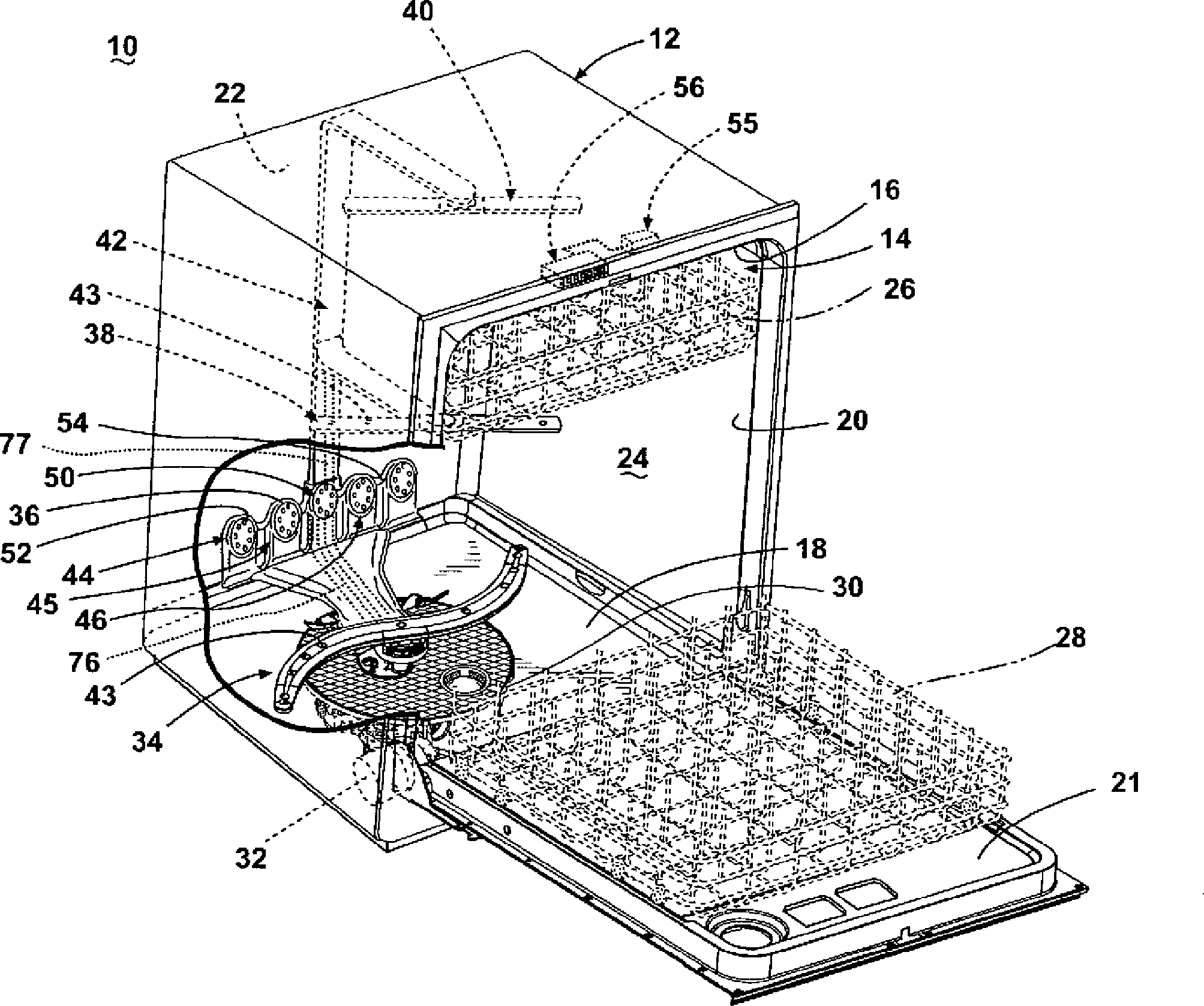
Die Erfindung betrifft einen Geschirrspülautomaten mit einer Waschkammer zur Aufnahme des zu behandelnden Spülguts. Die Waschkammer enthält auch eine bewegbare erste Sprüheinrichtung sowie eine zweite Sprüheinrichtung, einen Flüssigkeit-Strömungsweg, der die Waschkammer mit der ersten und der zweiten Sprüheinrichtung verbindet, ein in den Strömungsweg eingefügtes Umlenkventil mit einem Ventilelement, das um eine erste Rotationsachse zwischen einer ersten und einer zweiten Position drehbar ist, um aus der Waschkammer zwischen der ersten und der zweiten Sprüheinrichtung strömende Flüssigkeit wahlweise umzulenken, und einen Antrieb, von dem die erste Sprüheinrichtung in der Waschkammer bewegbar ist und der eine erste Antriebswelle aufweist, die um eine zweite Rotationsachse drehbar und betrieblich mit der ersten Sprüheinrichtung gekoppelt ist, um diese anzutreiben. Die erste und die zweite Achse verlaufen koaxial, um das Umlenkventil und den Antrieb teilweise zu integrieren und so einen gedrängten Aufbau zu erreichen.The invention relates to a dishwasher with a washing chamber for receiving the items to be treated. The wash chamber also includes a movable first spray device and a second spray device, a liquid flow path connecting the wash chamber to the first and second spray devices, a diverter valve inserted into the flow path having a valve member disposed about a first axis of rotation between a first and a first axis of rotation The second position is rotatable to selectively redirect fluid flowing from the wash chamber between the first and second spray devices, and a drive from which the first spray device is movable in the wash chamber and having a first drive shaft rotatable and operative about a second axis of rotation is coupled to the first spray device to drive them. The first and second axes are coaxial to partially integrate the diverter valve and the actuator to achieve a compact construction.

KURZBESCHREIBUNG DER ZEICHNUNGENBRIEF DESCRIPTION OF THE DRAWINGS

In den Zeichnungen:In the drawings:

1 ist eine Perspektive eines Geschirrspülers nach einer ersten Ausführungsform der Erfindung; 1 Fig. 13 is a perspective of a dishwasher according to a first embodiment of the invention;

2 zeigt den Geschirrspüler der 1 schaubildlich im Schnitt; 2 shows the dishwasher the 1 diagrammatically in section;

3 ist eine ausführlichere Perspektive eines Teils des Geschirrspülers der 1 mit einem Sumpf, einer Pumpanordnung, einer ersten unteren Sprüheinrichtung, den Antrieben und einer Ventilanordnung; 3 is a more detailed perspective of part of the dishwasher of the 1 a sump, a pumping assembly, a first lower sprayer, the drives, and a valve assembly;

4 ist eine Sprengdarstellung der Antriebe und der Ventilanordnung der 3; 4 is an exploded view of the drives and the valve assembly of 3 ;

5 ist ein Schnitt durch den in 3 gezeigten Teil des Geschirrspülers; 5 is a section through the in 3 shown part of the dishwasher;

6 zeigt weggeschnitten einen Unterteil eines Geschirrspülers nach einer zweiten Ausführungsform der Erfindung mit einem Ventilelement in einer ersten Position; und 6 shows cut away a lower part of a dishwasher according to a second embodiment of the invention with a valve element in a first position; and

7 zeigt weggeschnitten den unteren Teil des Geschirrspülers nach der zweiten Ausführungsform der Erfindung mit dem Ventilelement in einer zweiten Position. 7 shows cut away the lower part of the dishwasher according to the second embodiment of the invention with the valve element in a second position.

BESCHREIBUNG VON AUSFÜHRUNGSFORMEN DER ERFINDUNGDESCRIPTION OF EMBODIMENTS OF THE INVENTION

Die 1 und 2 zeigen eine erste Ausführungsform der Erfindung an einem Geschirrspülautomaten 10 mit einem (Schrank-)Gehäuse 12. Der Geschirrspüler 10 hat mit einem herkömmlichen Geschirrspülautomaten zahlreiche Merkmale gemein, die daher hier nicht ausführlich beschrieben sind, sofern nicht zum Verständnis der Erfindung erforderlich. Das Gehäuse 12 enthält einen Bottich 14 mit einer oberen und einer unteren Abschlussfläche 16, 18, die voneinander beabstandet sind, sowie beabstandeten Seitenflächen 20, einer Vorderfläche 21 und einer Rückwand 22. Die Wandflächen 16, 18, 20 21 und 22 bilden eine Spülkammer 24 zur Behandlung von Spülgut. Wie für den Fachmann einsichtig, kann die Vorderfläche 21 die Tür des Geschirrspülers 10 sein und an diesen schwenkbar angeschlagen sein, um die Spülkammer 24 zum Einbringen und Entfernen von Spülgut zugänglich zu machen. Zum leichteren Einbringen und Entfernen sind Spülguthalter in Form eines oberen und eines unteren Korbs 26, 28 typischerweise gleitend in die Spülkammer 24 einschieb- und aus ihr herausziehbar gelagert. Wie in der vorliegenden Beschreibung verwendet ist, soll der Begriff ”Spülgut” gattungsgemäß Artikel wie Geschirr u. dergl. umfassen, wie es im Geschirrspüler 10 behandelbar ist und ausdrücklich Schalen, Schüsseln, Teller, Besteck, Gläser und andere Glasartikel, Töpfe, Pfannen u. dergl. einschließt. Während die vorliegende Erfindung an Hand einer herkömmlichen Geschirrspüleinheit beschrieben ist, wie die 1 sie zeigt, ließe sie sich auch in andersartigen Geschirrspülern wie bspw. Spüleneinbau- oder Einschub-Geschirrspülern Implementieren.The 1 and 2 show a first embodiment of the invention on a dishwasher 10 with a (cabinet) housing 12 , The dishwasher 10 has in common with a conventional dishwasher common features, which are therefore not described in detail here, unless required for understanding of the invention. The housing 12 contains a tub 14 with an upper and a lower end surface 16 . 18 , which are spaced apart, and spaced side surfaces 20 , a front surface 21 and a back wall 22 , The wall surfaces 16 . 18 . 20 21 and 22 form a rinsing chamber 24 for the treatment of dishes. As for the expert, the front surface can be 21 the door of the dishwasher 10 be hinged and hinged to this, around the washing chamber 24 for the introduction and removal of items to be made accessible. To facilitate insertion and removal are Spülguthalter in the form of an upper and a lower basket 26 . 28 typically sliding into the wash chamber 24 inserted and pulled out of it. As used in the present description, the term "items to be washed" is intended generically to include items such as dishes and the like. The like include, as in the dishwasher 10 is treatable and expressly trays, bowls, plates, cutlery, glasses and other glassware, pots, pans u. the like. While the present invention is described with reference to a conventional dishwashing unit, such as 1 It shows that they could also be implemented in other types of dishwashers, such as dishwashers or rack-mounted dishwashers.

Die untere Abschlussfläche bzw. der Boden 18 des Geschirrspülers kann schräg geführt sein, um einen unteren Bottichbereich oder Sumpf 30 des Bottichs 14 zu bilden. In oder um einen Teil des Bodens 18 herum kann eine Pumpanordnung 32 in Strömungsverbindung mit dem Sumpf 30 angeordnet sein, um Spülflüssigkeit aus dem Sumpf 30 anzusaugen und mindestens einer ersten und zweiten unteren Sprüharmanordnung 36 zuzupumpen. Weist der Geschirrspüler auch eine umlaufende mittlere und eine obere Sprüheinrichtung 38 bzw. 40 auf, wie hier dargestellt, kann die Flüssigkeit den Sprüheinrichtungen 38, 40 durch eine Speiseleitung 42 gleichzeitig oder wahlweise zugepumpt werden, um bestimmungsgemäß versprüht zu werden.The lower end surface or the bottom 18 The dishwasher may be slanted to a lower tub area or sump 30 of the tub 14 to build. In or around part of the floor 18 around can be a pumping arrangement 32 in fluid communication with the sump 30 be arranged to flush out the sump 30 suck and at least a first and second lower Sprüharmanordnung 36 zuzupumpen. The dishwasher also has a rotating middle and a upper spraying device 38 respectively. 40 on, as shown here, the liquid can the sprayers 38 . 40 through a feed line 42 be pumped simultaneously or optionally to be sprayed as intended.

Wie dargestellt, befindet sich die erste untere Sprüheinrichtung 34 unter dem unteren Spülgutkorb 28. Die erste untere Sprüheinrichtung 34 ist ein Arm, der im Bottich 14 drehbar ausgeführt ist, um einen Strom Waschflüssigkeit aus mindestens einem Auslass 43 hauptsächlich aufwärts über einen Teil des Inneren des Bottichs 14 zu sprühen. Eine erste Spülzone kann von dem Sprühfeld gebildet sein, das die erste untere Sprüheinrichtung 34 in die Spülkammer 24 aussprüht. Der Sprühnebel aus der ersten unteren Sprüheinrichtung 34 ist typischerweise so gerichtet, dass er das Spülgut im unteren Spülgutkorb 28 spült. Die erste untere Sprüheinrichtung 34 kann optional auch einen Sprühnebel abwärts zum Sumpf 30 richten; zur Vereinfachung ist dieser Fall hier jedoch weder dargestellt noch beschrieben.As shown, the first lower sprayer is located 34 under the lower wash basket 28 , The first lower sprayer 34 is an arm in the tub 14 is rotatable to a flow of washing liquid from at least one outlet 43 mainly upwards over part of the interior of the tub 14 to spray. A first rinse zone may be formed by the spray field including the first lower sprayer 34 in the rinsing chamber 24 ejects. The spray from the first lower sprayer 34 is typically directed to hold the items to be washed in the lower rack 28 flushes. The first lower sprayer 34 Optionally, it can also spray down to the sump 30 judge; for simplicity, however, this case is neither illustrated nor described.

Die zweite untere Sprüheinrichtung 36 ist als am unteren Spülgutkorb 28 zur Rückseite der Spülkammer 24 hin angeordnet und als einen vertikal gerichteten Verteilerkopf bzw. Sprühverteiler 44 aufweisend gezeigt. Der Sprühverteiler 44 ist nicht auf diese Lage beschränkt; vielmehr kann er praktisch überall in der Spülkammer 24 liegen. Alternativ kann der Verteiler 44 unter dem unteren Korb 28 an oder unter der ersten unteren Sprüheinrichtung 34 liegen. Ein solcher Sprühverteiler ist ausführlich im US-Patent 7,594,513 mit dem Titel ”Multiple Wash Zone Dishwasher” (erteilt am 29. September 2009) beschrieben, auf das hiermit in seiner Gesamtheit Bezug genommen wird. Der Sprühverteiler des US-Patentes 7,594,513 kann zwei symmetrisch entgegengesetzte Hälften 45, 46 aufweisen, die jeweils zur wahlweisen Aufnahme der Spülflüssigkeit ausgeführt sind. Die Hälften 45, 46 des Verteilers 44 können jeweils eine Vielzahl von Sprühköpfen bzw. -düsen 50 mit Öffnungen 52 aufweisen, die zum Aussprühen von Spülflüssigkeit in den unteren Korb 28 ausgeführt sind. Die Sprühdüsen 50 können bezüglich des Verteilers 44 ortsfest oder drehbar sein. Weiterhin können die Hälften 45, 46 des Verteilers 44 jeweils mit einem oder mehr Durchlässen 54 zur Abgabe von Spülflüssigkeit an die Öffnungen 52 ausgeführt sein. Die Spülflüssigkeit kann unter Druck aus den Öffnungen 52 versprüht werden und daher einen intensivierten Sprühnebel erzeugen.The second lower sprayer 36 is as at the bottom Spülgutkorb 28 to the back of the washing chamber 24 arranged and as a vertically directed distributor head or spray distributor 44 having shown. The spray dispenser 44 is not limited to this situation; rather, it can be practically anywhere in the rinsing chamber 24 lie. Alternatively, the distributor 44 under the lower basket 28 at or below the first lower sprayer 34 lie. Such a spray dispenser is detailed in the U.S. Patent 7,594,513 entitled "Multiple Wash Zone Dishwasher" (issued Sep. 29, 2009), which is incorporated herein by reference in its entirety. The spray distributor of the U.S. Patent 7,594,513 can have two symmetrically opposite halves 45 . 46 have, which are each designed for selectively receiving the rinsing liquid. The halves 45 . 46 of the distributor 44 can each have a variety of spray heads or nozzles 50 with openings 52 for spraying irrigation fluid into the lower basket 28 are executed. The spray nozzles 50 can with respect to the distributor 44 be stationary or rotatable. Furthermore, the halves 45 . 46 of the distributor 44 each with one or more passages 54 for dispensing rinsing fluid to the openings 52 be executed. The rinse liquid may be under pressure from the openings 52 be sprayed and therefore produce an intensified spray.

Die zweite untere Sprüharmanordnung 36 kann konfiguriert sein, einen Strom Spülflüssigkeit aus den Öffnungen 52 in allgemein seitlicher Richtung über einen Teil des Inneren der Spülkammer 24 zu versprühen. Der Sprühnebel aus den Öffnungen 52 kann typischerweise so gerichtet sein, dass Spülgut im unteren Spülgutkorb 28 behandelt wird. Das von der zweiten unteren Sprüheinrichtung 36 in die Spülkammer 24 gerichtete Sprühfeld kann eine zweite Spülzone bilden. Wenn sowohl die erste als auch die zweite untere Sprüheinrichtung 34, 36 Sprühfelder ausgeben, können sich die erste und die zweite Sprühzone schneiden.The second lower spray arm assembly 36 can be configured to flush a stream of rinsing fluid out of the openings 52 in a generally lateral direction over a part of the interior of the washing chamber 24 to spray. The spray from the openings 52 can typically be directed so that items to be washed in the lower Spülgutkorb 28 is treated. That of the second lower sprayer 36 in the rinsing chamber 24 directed spray field can form a second rinse zone. If both the first and the second lower sprayer 34 . 36 Issue spray fields, the first and the second spray zone can intersect.

Wie dargestellt, liegt die mittlere Sprüharmanordnung 38 zwischen dem oberen und dem unteren Spülgutkorb 26, 28. Wie die erste untere Sprüheinrichtung 34 kann auch die mittlere Sprüharmanordnung 38 im Geschirrspüler 10 drehbar ausgeführt sein, um einen Strom Spülflüssigkeit aus mindestens einem Auslass 43 allgemein aufwärts über einen Teil des Inneren des Bottichs 14 zu sprühen. In diesem Fall ist der Sprühnebel aus der mittlere Sprüharmanordnung 38 auf Spülgut im oberen Spülgutkorb 26 gerichtet. Demgegenüber liegt die obere Sprüheinrichtung 40 über dem oberen Spülgutkorb 26; er richtet einen Sprühnebel aus Spülflüssigkeit allgemein abwärts und unterstützt die Behandlung von Spülgut in sowohl dem oberen als auch dem unteren Spülgutkorb 26, 28. Die Spülflüssigkeit kann Wasser oder ein Spülhilfsmittel jeweils eizeln oder in Kombination sein. Beispiele üblicher Waschhilfsmittel sind Detergentien, Fleckabschwächer bzw. -entferner, Klarspülmittel, Bleiche oder andere ähnliche Produkte, die ein gründliches Reinigen des Spülguts erleichtern.As shown, the middle spray arm assembly is located 38 between the upper and lower wash basket 26 . 28 , Like the first lower sprayer 34 may also be the middle Sprüharmanordnung 38 in the dishwasher 10 be made rotatable to a flow of rinsing fluid from at least one outlet 43 generally upwards over part of the interior of the tub 14 to spray. In this case, the spray is from the middle Sprüharmanordnung 38 on items to be washed in the upper rack 26 directed. In contrast, the upper spray is 40 above the upper rack 26 ; it generally directs a spray of flushing liquid downwards and aids in the treatment of items to be washed in both the upper and lower rack 26 . 28 , The rinsing liquid may be either water or a rinse aid or in combination. Examples of common detergents are detergents, stain removers, rinse aids, bleach or other similar products which facilitate thorough cleaning of the items to be washed.

Der Sumpf 30, die Pumpanordnung 32, die Sprüheinrichtungen 3440 und die Speiseleitung 42 bilden gemeinsam ein Flüssigkeits-Strömungs- und Umlaufsystem zum Versprühen von Spülflüssigkeit in der Spülkammer 24. Die Pumpanordnung 32 saugt Flüssigkeit aus dem Sumpf 30 und pumpt sie durch die Speiseleitung 42 einer oder mehrerer der Sprüheinrichtungen 3440 zu, die sie zurück in die Spülkammer 24 ausgeben, von wo sie in den Sumpf 30 zurückläuft und der Prozess sich wiederholt. Folglich verbindet der Flüssigkeits-Strömungsweg die Spülkammer 24 strömungsmäßig mit den Sprüheinrichtungen 3440. Der Geschirrspüler 10 kann weiterhin andere herkömmliche Systembestandteile wie zusätzliche Sprüharme oder -düsen, eine Ablasspumpe, ein Filter, eine Heizung usw. enthalten; diese Komponenten sind jedoch nicht erfindungswesentlich und daher hier nicht weiter beschrieben.The swamp 30 , the pumping arrangement 32 , the sprayers 34 - 40 and the feeders 42 together form a liquid flow and circulation system for spraying flushing liquid in the washing chamber 24 , The pumping arrangement 32 sucks liquid from the sump 30 and pump them through the feeders 42 one or more of the sprayers 34 - 40 to which they return to the rinsing chamber 24 spend from where they are in the swamp 30 runs back and the process repeats itself. As a result, the liquid flow path connects the purge chamber 24 fluidly with the sprayers 34 - 40 , The dishwasher 10 may also include other conventional system components such as additional spray arms or nozzles, a drain pump, a filter, a heater, etc .; However, these components are not essential to the invention and therefore not further described here.

Zum Ausführen eines Arbeitsprogramms können die Pumpanordnung 32 und verschiedene Systembestandteile des Geschirrspülers 10 an eine Steuerung 55 angeschlossen sein. In den Geschirrspüler 10 kann eine Anzahl unterschiedlicher Spülprogramme einprogrammiert sein, von denen ein Benutzer eines zum Reinigen einer Spülgut-Charge auswählen kann. Beispiele von Spülprogrammen sind u. a. solche für Normal-, Leicht- bzw. Porzellan- sowie stark verschmutztes Spülgut wie Töpfe und Pfannen sowie zum Klarspülen. Ein Bedienfeld bzw. eine Benutzerschnittstelle 56 auf dem Geschirrspüler 10, das an die Steuerung 55 angeschlossen ist, ermöglicht die Auswahl eines Spülprogramms. Die Benutzerschnittstelle 56 kann auf dem Gehäuse 12 oder außen auf der Tür angeordnet sein und Bedienelemente wie Skalen, Lampen, Schalter und Sichteinheiten aufweisen, mittels deren ein Benutzer Eingaben an die Steuerung 55 tätigen und Informationen über das gewählte Arbeitsprogramm erhalten kann. Alternativ ist das Arbeitsprogramm von der Steuerung 55 auf Grund der durch den Geschirrspüler 10 erfassten Verschmutzung des Spülguts selbsttätig wählbar, um die Reinigungsleistung des Geschirrspülers 10 für eine bestimmte Spülgut-Charge zu optimieren.To execute a work program, the pumping arrangement 32 and various system components of the dishwasher 10 to a controller 55 be connected. In the dishwasher 10 For example, a number of different wash programs may be programmed from which a user may select one to clean a wash lot batch. Examples of washing programs include those for normal, light or porcelain and heavily soiled items such as pots and pans and rinse. A control panel or user interface 56 on the dishwasher 10 that to the controller 55 is connected, allows the selection of a washing program. The user interface 56 can on the case 12 or arranged on the outside of the door and have controls such as scales, lamps, switches and viewing units, by means of which a user inputs to the controller 55 and receive information about the selected work program. Alternatively, the work program is from the controller 55 due to the dishwasher 10 detected contamination of the dishes automatically selectable to the cleaning performance of the dishwasher 10 to optimize for a specific wash lot batch.

Zur Klarheit stellen die 3 und 4 den Sumpf 30, die Pumpanordnung 32 und die erste untere Sprüheinrichtung 34 vom Rest des Geschirrspülers 10 getrennt dar. Gezeigt sind eine Sumpfplatte 57 mit einem Einlass 58, einem Montage-Basisteil 59 und einem Ventilantrieb 60, der eine Motoreinheit 61 und eine Antriebseinheit 62 aufweist. Ebenfalls gezeigt ist eine Umlenkventilanordnung 70 mit einem drehbaren Umlenkventilelement 71, das im Flüssigkeits-Strömungsweg liegen und vom Ventilantrieb 60 angetrieben sein kann, sowie ein Sprüheinrichtungs-Antrieb 80 zum Drehen der unteren Sprüheinrichtung 34. Die Sumpfplatte 57 ist Teil des Bodens 18 und daher des Bottichs 14. Der Einlass 58 im Basisteil kann in einem Teil der Sumpfplatte 57 ausgebildet und über die Pumpanordnung 32 und eine Leitung 58a strömungsmäßig mit dem Sumpf 30 verbunden sein.For clarity, the 3 and 4 the swamp 30 , the pumping arrangement 32 and the first lower sprayer 34 from the rest of the dishwasher 10 Separately dar. Shown are a swamp plate 57 with an inlet 58 , a mounting base 59 and a valve drive 60 , which is a motor unit 61 and a drive unit 62 having. Also shown is a diverter valve assembly 70 with a rotatable deflecting valve element 71 located in the fluid flow path and the valve drive 60 can be powered, as well as a sprayer drive 80 for turning the lower sprayer 34 , The swamp plate 57 is part of the soil 18 and therefore the tub 14 , The inlet 58 in the base part may be in a part of the sump plate 57 trained and the pumping arrangement 32 and a line 58a fluid with the sump 30 be connected.

Die Motor- und die Antriebseinheit 61, 62 können betrieblich mit dem Umlenkventilelement 71 gekoppelt sein. Insbesondere kann es sich bei der Motoreinheit 61 um einen Motor 63 handeln, der Energie bzw. Antriebskraft an die Antriebseinheit 62 liefert. Der Motor 63 kann außerhalb des Bottichs 14 (2) liegen. Die Antriebseinheit 62 kann eine Antriebswelle 64 aufweisen, die zwischen den Motor 63 und das Umlenkventilelement 71 eingefügt ist und letzteres mittels der Energie des Motors 63 antreibt. Das Umlenkventilelement 71 ist vom Ventilantrieb 60 um eine erste Rotationsachse 68 (5) in mehrere Positionen drehbar, um Flüssigkeit aus der Spülkammer 24 wahlweise auf die Sprüheinrichtungen 3440 zu lenken.The motor and drive unit 61 . 62 can operate with the diverter valve element 71 be coupled. In particular, it may be in the engine unit 61 about a motor 63 act, the energy or driving force to the drive unit 62 supplies. The motor 63 can outside the tub 14 ( 2 ) lie. The drive unit 62 can be a drive shaft 64 exhibit that between the engine 63 and the diverter valve element 71 is inserted and the latter by means of the energy of the engine 63 drives. The diverter valve element 71 is from the valve drive 60 around a first axis of rotation 68 ( 5 ) rotatable in several positions to remove liquid from the rinsing chamber 24 optionally on the sprayers 34 - 40 to steer.

Das Umlenkventilelement 71 ist als drehbare Umlenkscheibe 72 mit Öffnungen 73 dargestellt, die auf einen oder mehrere der Durchlässe 74a74c im Montage-Basisteil 59 ausrichtbar sind, um bei in eine der mehreren Positionen gedrehter Umlenkscheibe 72 Flüssigkeit im Sumpf 30 wahlweise auf die verschiedenen Sprüheinrichtungen 3440 zu schalten. Angedacht ist, dass die Umlenkscheibe 72 eine oder mehrere Öffnungen 73 enthält. Sie ist als zwei Öffnungen 73 enthaltend, der Montage-Basisteil 59 als drei Flüssigkeit-Durchlässe 74a74c enthaltend dargestellt.The diverter valve element 71 is as a rotatable deflection pulley 72 with openings 73 shown on one or more of the passages 74a - 74c in the mounting base 59 are aligned to turn in one of the several positions turntable 72 Liquid in the swamp 30 optionally on the different sprayers 34 - 40 to switch. It is thought that the deflecting disk 72 one or more openings 73 contains. It is as two openings 73 containing, the mounting base part 59 as three fluid passages 74a - 74c containing shown.

Wie die 35 weiterhin zeigen, kann die Antriebswelle 64 betrieblich mit der Umlenkscheibe 72 gekoppelt sein und diese antreiben, wie der Motor 63 die Antriebswelle 64 dreht. Die Öffnungen 73 lassen Spülwasser durch den Anordnungs-Unterteil 59 und in eine der vier Sprüheinrichtungen 3440 (12) fließen. Die Bewegung der Umlenkscheibe 72 zwischen den verschiedenen Positionen ermöglicht ein wahlweises Aufschalten der Spüflüssigkeit im Sumpf 30 auf die verschiedenen Sprüheinrichtungen 3440.As the 3 - 5 continue to show, the drive shaft 64 operational with the deflection pulley 72 be coupled and drive this, like the engine 63 the drive shaft 64 rotates. The openings 73 let rinse water through the assembly base 59 and in one of the four sprayers 34 - 40 ( 1 - 2 ) flow. The movement of the deflection pulley 72 between the various positions allows an optional switching of the rinsing liquid in the sump 30 on the different sprayers 34 - 40 ,

Bspw. verläuft ein unterer Sprühansatz 75 vertikal vom Durchlass 74a im Montage-Basisteil 59 zur ersten unteren Sprüheinrichtung 34. So kann der untere Sprühansatz 75 den Durchlass 74a strömungsmäßig mit der ersten unteren Sprüheinrichtung 34 verbinden. Die erste untere Sprüheinrichtung 34 kann drehbar auf den unteren Sprühansatz 75 aufgesetzt sein. Mehrere Kanäle 76, 77 können mit den anderen Durchlässen 74b, 74c ausgerichtet werden und von an deren Durchlässen 74b, 74c im Anordnungs-Unterteil 59 zur zweiten unteren Sprüheinrichtung 36 bzw. zur Speiseleitung 42 (2) verlaufen.For example. runs a lower spray attachment 75 vertically from the passage 74a in the mounting base 59 to the first lower sprayer 34 , So can the lower spray attachment 75 the passage 74a fluidly with the first lower sprayer 34 connect. The first lower sprayer 34 can rotate on the lower spray attachment 75 be set up. Several channels 76 . 77 can with the other passages 74b . 74c be aligned and from at their passages 74b . 74c in the arrangement lower part 59 to the second lower sprayer 36 or to the feed line 42 ( 2 ).

Die 4 zeigt an einer Sprengdarstellung die Teile, die den Sumpf 30, die Pumpanordnung 31, die erste untere Sprüheinrichtung 34, den Montage-Basisteil 59, den Ventilantrieb 60, die Umlenkventilanordnung 70 und einen Sprüheinrichtung-Antrieb 80 ausmachen. Wie in dieser Darstellung deutlicher zu sehen, weist der Sprüheinrichtung-Antrieb 80 eine Antriebswelle 82, einen Motor 84 und ein Getriebe aus einem Antriebszahnrad 86 und einem äußeren Zahnungsring 87 auf.The 4 shows an exploded view of the parts that make up the swamp 30 , the pumping arrangement 31 , the first lower sprayer 34 , the mounting base 59 , the valve drive 60 , the diverter valve assembly 70 and a sprayer drive 80 turn off. As can be seen more clearly in this illustration, the sprayer drive 80 a drive shaft 82 , a motor 84 and a transmission from a drive gear 86 and an outer gear ring 87 on.

In den 45 ist die Antriebswelle 64 mit einer mittigen Öffnung 78 zur Aufnahme der Antriebswelle 82 ausgeführt. Die Antriebswelle 82 ist von der mittigen Öffnung 78 der Antriebswelle 64 so aufnehmbar, dass sie in der mittigen Öffnung 78 um eine zweite Achse 82a frei drehen kann. Wie dargestellt, verlaufen die erste Rotationsachse 68 und die zweite Achse 82a koaxial miteinander, um die Umlenkventilanordnung 70 und den Sprüheinrichtungs-Antrieb 80 zu einer gedrängt aufgebauten Einheit zusammenzufassen, die im Geschirrspüler 10 mehr Raum zur Aufnahme anderer Systembestandteile belässt.In the 4 - 5 is the drive shaft 64 with a central opening 78 for receiving the drive shaft 82 executed. The drive shaft 82 is from the central opening 78 the drive shaft 64 so receivable that they are in the central opening 78 around a second axis 82a can rotate freely. As shown, the first axis of rotation run 68 and the second axis 82a coaxial with each other around the diverter valve assembly 70 and the sprayer drive 80 to summarize a crowded unit in the dishwasher 10 leaves more room to accommodate other system components.

Die Antriebswelle 82 kann einen Unterteil 83 haben, der mit dem Motor 84 betrieblich so gekoppelt sein kann, dass bei der Drehung des Motors 84 die Antriebswelle 82 mitdreht. Der Motor 84 kann dabei die Antriebswelle 82 unabhängig von der Antriebswelle 64 drehen. Weiterhin kann der Motor 84 in einer Vorwärts- und in der entgegengesetzten Richtung drehbar sein.The drive shaft 82 can a lower part 83 have that with the engine 84 Operationally coupled so that during the rotation of the engine 84 the drive shaft 82 rotates. The motor 84 can drive the shaft 82 independent of the drive shaft 64 rotate. Furthermore, the engine 84 in a forward and to be rotatable in the opposite direction.

Die Antriebswelle 82 hat einen Oberteil 85, der durch die mittige Öffnung 78 in der Antriebswelle 64, durch die Sumpfplatte 57, die Teil des Bodens 18 ist, und in den Unterteil des Bottichs 14 verläuft. Der Oberteil 85 kann von einem an einen Teil des unteren Sprühansatzes 75 angesetzten Halter 88 derart aufgenommen werden, dass der Oberteil 85 im Halter 88 frei drehbar ist. Der Oberteil 85 kann betrieblich mit dem Antriebszahnrad 86 gekoppelt sein, während das Antriebszahnrad 86 seinerseits mit dem äußeren Zahnungsring 87 kämmt. Der Zahnungsring 87 kann einen aufwärts vorstehenden tragenden Ansatz 89 aufweisen, der betrieblich mit der ersten unteren Sprüheinrichtung 34 so gekoppelt sein kann, dass die Drehbewegung des Zahnungsrings 87 und des Ansatzes 89 auf die erste untere Sprüheinrichtung 34 übertragen wird, um sie zu drehen. Die erste untere Sprüheinrichtung 34 kann um eine dritte Rotationsachse 99 drehen. Der untere Sprühansatz 75 kann ebenfalls mit dieser dritten Achse 99 ausgerichtet sein, um einen gedrängten Aufbau zu erreichen. Der Ansatz 89 kann vielerlei Formen annehmen; wie dargestellt, kann er einen Durchlass 90 enthalten, der eine Strömungsverbindung zwischen dem unteren Sprühansatz 75 und der ersten unteren Sprüheinrichtung 34 herstellt.The drive shaft 82 has a shell 85 passing through the central opening 78 in the drive shaft 64 , through the swamp plate 57 that part of the soil 18 is, and in the bottom of the tub 14 runs. The top part 85 can be from one to a part of the lower spray attachment 75 attached holder 88 be taken in such a way that the upper part 85 in the holder 88 is freely rotatable. The top part 85 Can work with the drive gear 86 be coupled while the drive gear 86 in turn, with the outer toothing ring 87 combs. The toothing ring 87 can be an upwardly projecting bearing approach 89 which is operative with the first lower sprayer 34 may be coupled so that the rotational movement of the toothing ring 87 and the approach 89 on the first lower sprayer 34 is transferred to turn it. The first lower sprayer 34 can be about a third axis of rotation 99 rotate. The lower spray attachment 75 can also use this third axis 99 be aligned in order to achieve a compact construction. The approach 89 can take many forms; as shown, he can pass 90 containing a flow connection between the lower spray attachment 75 and the first lower sprayer 34 manufactures.

Betrachtet man den Sprüheinrichtungs-Antrieb 80 ausführlicher, weist die Antriebswelle 82 eine Rotationsachse 82a auf, die aus einer Rotationsachse 99 der ersten unteren Sprüheinrichtung 34 versetzt verläuft. Wird die Antriebswelle 82 gedreht, dreht das Antriebszahnrad 86 mit; die Drehung des Antriebszahnrads 86 bewirkt eine Drehung des Zahnungsrings 87. Der Zahnungsring 87 ist vom unteren Sprühansatz 75 gegen eine exzentrische Drehung arretiert und dreht stattdessen um eine dritte Achse 99. Die erste untere Sprüheinrichtung 34, die über den Ansatz 89 mit dem Zahnungsring 87 gekoppelt ist, dreht mit letzterem mit. Da ein vollständiger Umlauf des Antriebsrads 86 nur einen teilweisen Umlauf des Zahnungsrings 87 erzeugt, wird die Drehzahl der ersten unteren Sprüheinrichtung 34 gegenüber der des Motors 84 verringert. Obgleich das dargestellte Getriebe ein Antriebszahnrad und einen Zahnungsring 86, 87 aufweist, lassen sich hier auch andere Getriebearten einsetzen.Looking at the sprayer drive 80 in more detail, has the drive shaft 82 a rotation axis 82a on, coming from a rotation axis 99 the first lower sprayer 34 staggered. Will the drive shaft 82 turned, the drive gear rotates 86 With; the rotation of the drive gear 86 causes a rotation of the gear ring 87 , The toothing ring 87 is from the lower spray attachment 75 locked against an eccentric rotation and instead rotates about a third axis 99 , The first lower sprayer 34 that about the approach 89 with the toothing ring 87 is coupled, rotates with the latter. As a complete circulation of the drive wheel 86 only a partial revolution of the toothing ring 87 generates, the speed of the first lower sprayer 34 opposite to the engine 84 reduced. Although the illustrated gear has a drive gear and a gear ring 86 . 87 has, other types of transmission can be used here.

Wie die 5 zeigt, bietet die montierte Umlenkventilanordnung 70 Strömungswege vom Sumpf 30 zu mindestens einer der Sprüheinrichtungen 3440; vergl. die Pfeile. Die Strömungswege werden von den komplementären Durchlässen 74a74c im Basisteil 59 der Anordnung, den Öffnungen 73 in der Umlenkscheibe 72 und dem unteren Sprühansatz 75 oder den Kanälen 76, 77 gebildet (3). Die Bewegung der Öffnungen 73 relativ zu den Durchlässen 74a74c verbindet den über die Pumpanordnung 32 und die Leitung 58a mit dem Sumpf 30 verbunden Platteneinlass 58 mit einer oder mehreren der Sprüheinrichtungen 3440.As the 5 shows offers the mounted diverter valve assembly 70 Flow paths from the swamp 30 to at least one of the sprayers 34 - 40 ; compare the arrows. The flow paths are from the complementary passages 74a - 74c in the base part 59 the arrangement, the openings 73 in the deflection pulley 72 and the lower spray attachment 75 or the channels 76 . 77 educated ( 3 ). The movement of the openings 73 relative to the passages 74a - 74c connects via the pumping arrangement 32 and the line 58a with the swamp 30 connected disk inlet 58 with one or more of the sprayers 34 - 40 ,

Im Betrieb des Geschirrspülers 10 kann die Umlenkventilanordnung 70 dazu dienen, das Volumen des Flüssigkeitsstroms aus der Pumpanordnung 32 zu den Sprüheinrichtungen 3440 zu steuern. An einem zum Einsprühen von Spülflüssigkeit in die Spülkammer 24 geeigneten Zeitpunkt während des Spülprogramms signalisiert die Steuerung 55 der Pumpanordnung 32, der Ventilanordnung 70 Spülflüssigkeit zuzupumpen. Abhängig vom jeweils laufenden Spülprogramm kann die Steuerung 55 auch den einen oder den anderen Antrieb 60 bzw. 80 betätigen.In operation of the dishwasher 10 can the diverter valve assembly 70 serve to increase the volume of liquid flow from the pumping assembly 32 to the sprayers 34 - 40 to control. At one for spraying rinsing liquid into the rinsing chamber 24 appropriate time during the wash program signals the controller 55 the pumping arrangement 32 , the valve assembly 70 Pump rinsing liquid. Depending on the current rinse program, the controller can 55 also one or the other drive 60 respectively. 80 actuate.

Mit dem Betätigen des Motors 63 des Ventilantriebs 60 durch die Steuerung 55 wird die Antriebswelle 64 gedreht, was ein Drehen der drehbaren Umlenkscheibe 72 bewirkt. Mit der Drehung der drehbaren Umlenkscheibe 72 werden die Öffnungen 73 gedreht, um den Platteneinlass 58 strömungsmäßig mit den verschiedenen Durchlässen 74a74c im unteren Basisteil 59 zu verbinden, was durch vollständiges oder teilweises Ausrichten einer oder mehrerer der Öffnungen 73 auf einen oder mehr der Durchlässe 74a74c erfolgt. Die Dauer, für die die Öffnungen 73 mit den Durchlässen 74a-74c jeweils strömungsmäßig verbunden sind, bestimmt die Dauer, für die die verschiedenen Sprüheinrichtungen 3440 die Flüssigkeit jeweils versprühen. Nachdem die erwünschte Strömungsverbindung einer oder mehr der Sprüheinrichtungen 3440 mit der Pumpe 32 erreicht ist, kann der Motor 63 deaktiviert werden, so dass die Strömungsverbindung erhalten bleibt, oder er kann aktiviert bleiben, um die Antriebswelle weiter 64 so zu drehen, dass die Sprüheinrichtungen 3440 nacheinander mit dem Sumpf 30 verbunden werden. Angemerkt sei, dass die Speiseleitung 42 sowohl der mittleren als auch der oberen Sprüheinrichtung 38, 40 Wasser zuführt. So lässt sich ein zusätzliches Ventil (nicht gezeigt) vorsehen, um Wasser auf die eine oder die andere Sprüheinrichtung zu lenken. Alternativ kann Spülflüssigkeit aus der Speiseleitung 42 jeweils teilweise auf die Sprüheinrichtungen 38, 40 gelenkt werden.By pressing the motor 63 of the valve drive 60 through the controller 55 becomes the drive shaft 64 Turned, causing a turning of the rotating deflecting disk 72 causes. With the rotation of the rotatable deflection pulley 72 be the openings 73 turned to the plate inlet 58 fluidly with the various passages 74a - 74c in the lower base part 59 connect, by fully or partially aligning one or more of the openings 73 on one or more of the culverts 74a - 74c he follows. The duration for which the openings 73 with the passages 74a-74c are each fluidly connected, determines the duration for which the various sprayers 34 - 40 spray the liquid in each case. After the desired flow connection of one or more of the sprayers 34 - 40 with the pump 32 is reached, the engine can 63 be deactivated, so that the flow connection is maintained, or he may remain activated to continue the drive shaft 64 to turn so that the sprayers 34 - 40 one after the other with the swamp 30 get connected. It should be noted that the feedline 42 both the middle and the upper sprayer 38 . 40 Supplying water. Thus, an additional valve (not shown) may be provided to direct water to one or the other of the sprayers. Alternatively, rinsing fluid from the feed line 42 each partially on the sprayers 38 . 40 be steered.

Im Betrieb des Geschirrspülers 10 kann die Steuerung 55 auch eingesetzt werden, um den Motor 84 des Sprüheinrichtungs-Antriebs 80 zu steuern, was die Drehung der Antriebswelle 82 bewirkt. Das Antriebszahnrad 86 und der Zahnungsring 87 bilden ein Zahnradgetriebe, das die Antriebswelle 82 mit der ersten unteren Sprüheinrichtung 34 verbindet, so dass die Drehung der Antriebswelle 82 um die zweite Achse 82a eine Drehung der ersten unteren Sprüheinrichtung 34 um die dritte Achse 99 über das Getriebe ergibt. Der Motor 84 und andere Bestandteile des Sprüheinrichtungs-Antriebs 80 können in einer Vorwärtsrichtung und der entgegengesetzten Richtung arbeiten, so dass die erste untere Sprüheinrichtung 34 in einer ersten und einer zur ersten entgegengesetzten zweiten Richtung antreibbar sein kann. Diese bidirektionale Drehung kann zur Reinigung von Spülgut im unteren Spülgutkorb 28 beitragen. Die Dauer der Drehung des Motors 84 in jeder Richtung ist von der Steuerung 55 steuerbar. Weiterhin kann die Steuerung 55 den Motor 84 so ansteuern, dass er die erste untere Sprüheinrichtung 34 verlangsamt oder auch anhält. Das Verlangsamen bzw. Anhalten der ersten unteren Sprüheinrichtung 34 kann in bestimmten Bereichen der Spülkammer 24 einen besseren Reinigungseffekt ermöglichen. Während dieses Intervalls kann die Steuerung 55 die Pumpanordnung 32 auch anweisen, einer oder mehreren der Sprüheinrichtungen 3440 Flüssigkeit zuzuführen. So lässt sich die erste untere Sprüheinrichtung 34 in den Stillstand bringen, während ihr die Pumpanordnung 32 Flüssigkeit zupumpt.In operation of the dishwasher 10 can the controller 55 also be used to the engine 84 of the sprayer drive 80 to control what the rotation of the drive shaft 82 causes. The drive gear 86 and the teething ring 87 form a gear transmission that drives the drive shaft 82 with the first lower sprayer 34 connects, so that the rotation of the drive shaft 82 around the second axis 82a a rotation of the first lower sprayer 34 around the third axis 99 about the transmission results. The motor 84 and other components of the Sprüheinrichtungs Drive 80 can work in a forward direction and in the opposite direction, so that the first lower sprayer 34 can be drivable in a first and a second direction opposite to the first. This bidirectional rotation can be used to clean items in the lower rack 28 contribute. The duration of the rotation of the engine 84 in every direction is from the controller 55 controllable. Furthermore, the controller 55 the engine 84 so drive that he has the first lower sprayer 34 slows or stops. Slowing or stopping the first lower sprayer 34 can in certain areas of the washing chamber 24 allow a better cleaning effect. During this interval, the controller can 55 the pumping arrangement 32 also instruct one or more of the sprayers 34 - 40 To supply liquid. This is how the first lower spraying device works 34 bring it to a standstill while you're pumping 32 Pumping up liquid.

Die 6 und 7 zeigen einen Geschirrspüler 100 nach einer zweiten Ausführungsform der Erfindung, die der ersten Ausführungsform 10 entspricht. Daher sind gleiche Teile mit den gleichen, um 100 erhöhten Bezugszeichen gekennzeichnet, wobei angemerkt sei, dass die Beschreibung der gleichen Teile der ersten Ausführungsform gleichermaßen für die der zweiten gilt, sofern nichts anderes festgestellt ist.The 6 and 7 show a dishwasher 100 according to a second embodiment of the invention, that of the first embodiment 10 equivalent. Therefore, the same parts are denoted by the same reference numerals increased by 100, it being noted that the description of the same parts of the first embodiment applies equally to those of the second, unless otherwise stated.

Ein Unterschied zwischen der ersten und der zweiten Ausführungsform ist, dass der Geschirrspüler 100 eine Sumpfanordnung aufweist, die eine den Sumpf 130 umschließende Vertiefung, ein Flüssigkeits-Umwälzsystem mit einem Umleitkopf 191 sowie einen einzigen Antrieb 191a zum Antrieb sowohl des Ventilelements 171 als auch der ersten unteren Sprüheinrichtung 134 beinhaltet. Die Pumpanordnung 132 verbindet den Sumpf 30 strömungsmäßig mit dem Umlenkkopf 191, und zwar über eine Einlassleitung 158a, die mit einem Ende am Ablauf der Pumpe 132 und mit dem anderen Ende am Platteneinlass 158 liegt. Die Sumpfanordnung hat eine obere Abschlussfläche bzw. Sumpfplatte 157, die Teil des Bodens 118 ist, und der Umlenkkopf 191 steht über die Sumpfplatte 157 hinaus vor. Insbesondere ist der Umlenkkopf 191 als Haube dargestellt, die über den Boden 118 hinaus vorsteht.A difference between the first and the second embodiment is that the dishwasher 100 a sump assembly having a sump 130 enclosing recess, a liquid recirculation system with a diverter head 191 and a single drive 191a for driving both the valve element 171 as well as the first lower sprayer 134 includes. The pumping arrangement 132 connects the swamp 30 fluidly with the deflection 191 , via an inlet pipe 158a with one end at the drain of the pump 132 and with the other end at the disk inlet 158 lies. The sump assembly has an upper end surface or sump plate 157 that part of the soil 118 is, and the deflection 191 stands over the swamp plate 157 out before. In particular, the deflection is 191 represented as a hood, over the ground 118 protrudes beyond.

Ein erster Abzweigkanal 192a verläuft vom Umlenkkopf weg und verbindet das Ventilelement 171 strömungsmäßig mit der ersten unteren Sprüheinrichtung 134, während ein zweiter Abzweigkanal 192b vom Umlenkkopf weg verläuft und das Ventilelement 171 strömungsmäßig mit der zweiten unteren Sprüheinrichtung 136 (nicht gezeigt) verbindet. Das Ventilelement 171 befindet sich im Umlenkkopf 191; es ist um eine erste Rotationsachse 168 zwischen mindestens einer ersten Position (6) und einer zweiten Position (7) drehbar, um Flüssigkeit aus dem Sumpf 130 wahlweise der ersten und der zweiten unteren Sprüheinrichtung 134 bzw. 136 zuzuführen. Der erste und der zweite Abzweigkanal 175, 176 verlaufen von der Haube weg über den Boden 118. Wie dargestellt, verläuft der erste Abzweigkanal 175 von der Haube vertikal weg, wobei die erste untere Sprüheinrichtung 134 an den Oberteil des ersten Abzweigkanals 715 drehbar angesetzt ist, während der zweite Abzweigkanal 76 von der Haube radial weg und über den Boden 118 verläuft.A first branch channel 192a runs away from the deflection head and connects the valve element 171 fluidly with the first lower sprayer 134 while a second branch channel 192b away from the deflection head and the valve element 171 fluidly with the second lower sprayer 136 (not shown) connects. The valve element 171 is located in the deflection head 191 ; it is a first axis of rotation 168 between at least one first position ( 6 ) and a second position ( 7 ) rotatable to remove liquid from the sump 130 optionally the first and second lower sprayers 134 respectively. 136 supply. The first and the second branch channel 175 . 176 run away from the hood over the ground 118 , As shown, the first branch channel runs 175 away from the hood vertically, with the first lower sprayer 134 to the top of the first branch channel 715 is rotatably attached, while the second branch channel 76 away from the hood and over the ground 118 runs.

Der Antrieb 191a dreht das Umlenk-Ventilelement 171, um Flüssigkeit aus dem Sumpf 130 wahlweise um- und auf die Sprüheinrichtungen 34, 36 zu lenken, und er dreht auch die erste untere Sprüheinrichtung 134. Der Antrieb 191a weist eine gemeinsame Antriebswelle 193 auf, die von einem gemeinsamen Motor 194 angetrieben wird und betrieblich mit sowohl der ersten unteren Sprüheinrichtung 134 als auch dem Ventilelement 171 gekoppelt ist. Durch wahlweises Betätigen der gemeinsamen Antriebswelle 193 wird die erste untere Sprüheinrichtung 134 wie auch das Ventilelement 171 zwischen mindestens der ersten und der zweiten Position gedreht, um den Flüssigkeitsfluss aus dem Sumpf 130 zur ersten und zweiten unteren Sprüheinrichtung 134 bzw. 136 wahlweise zu steuern.The drive 191a turns the diverting valve element 171 to get liquid from the sump 130 optionally on and on the sprayers 34 . 36 to steer, and he also turns the first lower sprayer 134 , The drive 191a has a common drive shaft 193 on, by a common engine 194 is powered and operational with both the first lower sprayer 134 as well as the valve element 171 is coupled. By selectively actuating the common drive shaft 193 becomes the first lower sprayer 134 as well as the valve element 171 rotated between at least the first and the second position to the liquid flow from the sump 130 to the first and second lower sprayers 134 respectively. 136 optionally to control.

Die gemeinsame Antriebswelle 193 ist dargestellt als eine Welle 195 aufweisend, die mit dem einen Ende mit dem Motor 194 und mit dem anderen Ende über ein Zahnradgetriebe 196 mit der ersten unteren Sprüheinrichtung 134 gekoppelt ist, wobei eine Hülse 197 die Welle 195 umgibt und sie mit dem Ventilelement 171 verbindet. Wie die 6 zeigt, liegt die Hülse 197 vollständig unter dem Boden 118 und verläuft die Welle 195 durch den und über dem Boden 118. Der über dem Boden 118 liegende Teil der Welle 195 ist über das Zahnradgetriebe 196 so mit der ersten unteren Sprüheinrichtung 134 gekoppelt, dass durch die Drehung der Welle 195 durch den Motor 194 die Sprüheinrichtung 134 bewegt wird. Der Geschirrspüler 10 ist als eine Filtereinheit 198 aufweisend dargestellt, die in der den Sumpf 130 bildenden Vertiefung herausnehmbar angeordnet sein kann. Das Zahnradgetriebe 196 ist gedrängt aufgebaut und entspricht im Wesentlichen dem der ersten Ausführungsform, wobei kein Teil des Zahnradgetriebes 196 sich über der den Sumpf 130 bildenden Vertiefung oder der Filtereinheit 198 befindet.The common drive shaft 193 is shown as a wave 195 having, with one end to the engine 194 and with the other end via a gear transmission 196 with the first lower sprayer 134 coupled, wherein a sleeve 197 the wave 195 surrounds and she with the valve element 171 combines. As the 6 shows, lies the sleeve 197 completely under the ground 118 and the wave passes 195 through and above the ground 118 , The above the ground 118 lying part of the wave 195 is about the gear transmission 196 so with the first lower sprayer 134 coupled that by the rotation of the shaft 195 through the engine 194 the sprayer 134 is moved. The dishwasher 10 is as a filter unit 198 shown in the marsh 130 forming recess can be arranged removably. The gear transmission 196 is compressed and essentially corresponds to that of the first embodiment, wherein no part of the gear transmission 196 above the swamp 130 forming depression or the filter unit 198 located.

Sowohl die Hülse 197 als auch die Welle 195 lassen sich mit dem Motor 194 wahlweise koppeln mittels einer Kupplungsmechanik 200, die in den 6 und 7 schaubildlich gezeigt ist. Die Kupplungsmechanik 200 kann betrieblich an die Steuerung 155 angeschlossen sein, die sie ein- und ausrücken kann, um die Welle 195 und die Hülse 197 mit dem Motor 194 zu verbinden bzw. von ihm zu trennen. Die Kupplungsmechanik 200 ist so betätigbar, dass entweder die Welle 195 oder die Hülse 197 mit dem Motor 194 gekoppelt wird. Alternativ lassen sich sowohl die Welle 195 als auch die Hülse 197 von der Kupplungsmechanik 200 mit dem Motor 194 koppeln, so dass der Motor 194 die Welle 195 und auch die Hülse 197 dreht.Both the sleeve 197 as well as the wave 195 can be with the engine 194 optionally coupled by means of a coupling mechanism 200 that in the 6 and 7 is shown diagrammatically. The coupling mechanism 200 can be operational to the controller 155 be connected, they can move in and out to the shaft 195 and the sleeve 197 With the engine 194 to connect or disconnect from it. The coupling mechanism 200 is so operable that either the shaft 195 or the sleeve 197 with the engine 194 is coupled. Alternatively, both the wave can be 195 as well as the sleeve 197 from the clutch mechanics 200 with the engine 194 pair, leaving the engine 194 the wave 195 and also the sleeve 197 rotates.

Werden im Betrieb sowohl die Hülse 197 als auch die Hülse 195 mit dem Motor 194 gekoppelt, nimmt der arbeitende Motor sowohl die Welle 195 als auch die Hülse 197 in Drehung mit. Die Drehung der Welle 195 wird über das Zahnradgetriebe 196 übertragen und bewirkt eine Drehung der ersten unteren Sprüheinrichtung 134. Die drehende Welle 197 bewirkt ein Drehen des Ventilelements 171 zwischen mindestens einer ersten und einer zweiten Position (6 bzw. 7). Die Hülse 197 kann mit dem Motor 194 gekoppelt bleiben, so dass bei arbeitender Pumpanordnung 132 Flüssigkeit weiter zwischen der ersten und der zweiten unteren Sprüheinrichtung 134 bzw. 136 umgelenkt wird. Alternativ kann die Hülse 197 vom Motor 194 getrennt werden, wenn das Ventilelement 171 sich weder in der ersten noch der zweiten Position (6 bzw. 7) befindet.Be in operation both the sleeve 197 as well as the sleeve 195 with the engine 194 coupled, the working motor takes both the shaft 195 as well as the sleeve 197 in rotation with. The rotation of the shaft 195 is about the gear transmission 196 transferred and causes a rotation of the first lower sprayer 134 , The rotating shaft 197 causes a rotation of the valve element 171 between at least one first and one second position ( 6 respectively. 7 ). The sleeve 197 can with the engine 194 remain coupled, so that when working pump assembly 132 Liquid continues between the first and second lower sprayers 134 respectively. 136 is diverted. Alternatively, the sleeve 197 from the engine 194 be disconnected when the valve element 171 neither in the first nor in the second position ( 6 respectively. 7 ) is located.

Erwogen ist auch eine alternativ aufgebaute gemeinsame Antriebswelle 193. Als (die Erfindung nicht einschränkendes) Beispiel kann die Hülse 197 direkt mit dem Zahnradgetriebe 196 gekoppelt sein, die Welle 195 direkt mit dem Ventilelement 171. Ebenfalls erwogen ist, an Stelle der Kupplungsmechanik 200 einen separaten Antrieb oder Motor betrieblich mit der Hülse 197 zu koppeln, der sie unabhängig von der Bewegung der Welle 195 dreht. Auf diese Weise wären die Welle 195 und die Hülse 197 ebenfalls unabhängig voneinander drehbar.Considered is also an alternative constructed common drive shaft 193 , As an example (not limiting the invention), the sleeve 197 directly with the gear transmission 196 be coupled, the wave 195 directly with the valve element 171 , It is also considered, instead of the clutch mechanism 200 a separate drive or motor operational with the sleeve 197 to couple them regardless of the movement of the shaft 195 rotates. That would be the wave 195 and the sleeve 197 also independently rotatable.

Bei traditionellen Geschirrspüler-Sprüharmen bildet umgelenktes Wasser einen hydraulischen Antrieb zu deren Drehung. Dieser hydraulische Antrieb hängt vom Förderdruck und -durchsatz der Pumpe ab und die Sprüharme lassen sich für eine gegebene Pumpe nur zum Umlauf mit Nenndrehzahlen konstruieren. Auch arbeiten diese hydraulisch angetriebenen Sprüharme nur in einer Richtung. Es ist auch nicht unüblich, dass sie im Arbeitsprogramm teilweise in der Drehung blockieren, was ihre Reinigungsleistung beeinträchtigt. Die oben beschriebenen Ausführungsformen der Erfindung lassen zu, die erste untere Sprüheinrichtung 34, 134 motorisch und damit wirkungsvoller anzutreiben und auch deren Drehzahl und -richtung besser zu kontrollieren und zu steuern. Wird die Position der ersten unteren Sprüheinrichtung 34, 134 unabhängig von der durch sie strömenden Flüssigkeit gesteuert, lassen sich zahlreiche nützliche Sprühstrategien anwenden. Bspw. kann man die erste untere Sprüheinrichtung 34, 134 verlangsamen oder in den Stillstand bringen, wo ein stärkeres Besprühen erwünscht ist – wenn bspw. die erste untere Sprüheinrichtung 34, 134 in die Ecken des Spülgutkorbs oder in Bereiche mit starker Verschmutzung gerichtet ist. Dies lässt zu, dem Arbeitsprogramm und dem Geschirrspüler weitere Leistungsmerkmale hinzuzufügen – bspw. ein zonenweises Spülen. Die Fähigkeit, sowohl die Drehzahl der ersten unteren Sprüheinrichtung 34, 134 zu beeinflussen, als auch die einer Richtungsumkehr derselben ergeben eine verbesserte Spülabdeckung des Spülguts.In traditional dishwasher spray arms, deflected water forms a hydraulic drive to rotate it. This hydraulic drive depends on the delivery pressure and flow rate of the pump, and the spray arms can only be designed to circulate at rated speeds for a given pump. Also, these hydraulically driven spray arms work only in one direction. It is also not uncommon for them to partially block rotation in the work program, affecting their cleaning performance. The embodiments of the invention described above allow the first lower sprayer 34 . 134 To drive motor and thus more effective and also better control and control their speed and direction. Will the position of the first lower sprayer 34 . 134 Regardless of the fluid flowing through it, many useful spray strategies can be used. For example. you can get the first lower sprayer 34 . 134 slow down or bring to a standstill, where a stronger spraying is desired - if, for example, the first lower sprayer 34 . 134 directed into the corners of the wash basket or in areas of heavy contamination. This allows to add more performance features to the work program and the dishwasher - for example, a zoned rinse. The ability to both the speed of the first lower sprayer 34 . 134 to influence, as well as a direction reversal of the same result in an improved Spülabdeckung the dishes.

Die oben beschriebenen Ausführungsformen der Erfindung ermöglichen auch der Steuerung, eine Auswahl der Sprüheinrichtungen zu treffen, die während eines Spülprogramms tätig werden sollen. Auf diese Weise lassen sich die Reinigungswirkung und die Ressourcennutzung optimieren, indem man Spülflüssigkeit nur in Bereiche sprüht, in denen sich Spülgut befindet. Dadurch wird kein Spülwasser verschwendet und lassen sich sowohl Zeit als auch Energie einsparen.The above-described embodiments of the invention also allow the controller to make a selection of spray devices to operate during a wash program. In this way, the cleaning effect and the resource use can be optimized by spraying flushing liquid only in areas where items to be washed is. As a result, no rinse water is wasted and can save both time and energy.

Während die Erfindung speziell in Verbindung mit bestimmten Ausführungsformen derselben beschrieben wurde, ist einzusehen, dass dies lediglich zur Erläuterung, nicht einschränkend erfolgte. Der Umfang der beigefügten Ansprüche ist so allgemein auszulegen, wie es der Stand der Technik zulässt. Bspw. wird erwogen, dass die Erfindung sich von den in den 16 gezeigten Ausführungen durch andere die Strömung der Spülflüssigkeit steuernde Leitungen, Spülgutkörbe, Sprüheinrichtungen, Dichtungen u. dergl. unterscheiden kann.While the invention has been particularly described in connection with certain embodiments thereof, it will be understood that this has been done by way of illustration, not limitation. The scope of the appended claims is to be interpreted as generally as permitted by the prior art. For example. It is considered that the invention differs from those in the 1 - 6 shown embodiments by other the flow of the rinsing liquid controlling lines, Spülgutkörbe, sprayers, seals u. can distinguish the like.

ZITATE ENTHALTEN IN DER BESCHREIBUNG QUOTES INCLUDE IN THE DESCRIPTION

Diese Liste der vom Anmelder aufgeführten Dokumente wurde automatisiert erzeugt und ist ausschließlich zur besseren Information des Lesers aufgenommen. Die Liste ist nicht Bestandteil der deutschen Patent- bzw. Gebrauchsmusteranmeldung. Das DPMA übernimmt keinerlei Haftung für etwaige Fehler oder Auslassungen.This list of the documents listed by the applicant has been generated automatically and is included solely for the better information of the reader. The list is not part of the German patent or utility model application. The DPMA assumes no liability for any errors or omissions.

Zitierte PatentliteraturCited patent literature

  • US 7594513 [0014, 0014] US 7594513 [0014, 0014]

Claims (22)

Geschirrspülautomat zum Spülen von Spülgut entsprechend einem Arbeitsprogramm, mit: einem Bottich, der mindestens teilweise eine Spülkammer zur Aufnahme von zu behandelndem Spülgut umschließt; einer ersten Sprüheinrichtung, die in der Spülkammer bewegbar in dieser gelagert ist; einer zweiten Sprüheinrichtung, die in der Spülkammer angeordnet ist; einem Flüssigkeits-Strömungsweg, der die Spülkammer mit der ersten und der zweiten Sprüheinrichtung verbindet; einem Umlenkventil, das in den Flüssigkeits-Strömungsweg eingefügt ist und ein Ventilelement aufweist, das um eine erste Rotationsachse zwischen einer ersten und einer zweiten Position drehbar ist, um Flüssigkeit aus der Spülkammer zwischen der ersten und der zweiten Sprüheinrichtung umzulenken; und einem Antrieb, der die erste Sprüheinrichtung in der Spülkammer bewegt und eine erste Antriebswelle aufweist, die um eine zweite Rotationsachse drehbar und betrieblich mit der ersten Sprüheinrichtung gekoppelt ist, um eine Bewegung der letzteren zu bewirken; wobei die erste und die zweite Rotationsachse koaxial verlaufen, um das Umlenkventil mit dem Antrieb teilweise zusammenzufassen und so einen gedrängten Aufbau zu erreichen.Dishwasher for rinsing dishes according to a work program, comprising: a tub that at least partially encloses a rinsing chamber for receiving items to be treated; a first spraying device, which is mounted in the washing chamber movable therein; a second spraying device disposed in the washing chamber; a liquid flow path connecting the rinsing chamber to the first and second spraying devices; a diverter valve inserted in the fluid flow path and having a valve element rotatable about a first axis of rotation between a first and a second position to redirect fluid from the rinsing chamber between the first and second spray devices; and a drive which moves the first spray means in the wash chamber and has a first drive shaft which is rotatable about a second rotation axis and operably coupled to the first spray means to effect movement of the latter; wherein the first and the second axis of rotation are coaxial to partially combine the diverter valve with the drive to achieve a compact construction. Geschirrspülautomat nach Anspruch 1, dadurch gekennzeichnet, dass die erste Sprüheinrichtung eine drehbare Sprüheinrichtung aufweist, die in der Spülkammer um eine dritte Rotationsachse drehbar gelagert ist.Dishwasher according to claim 1, characterized in that the first spraying device comprises a rotatable spraying device, which is rotatably mounted in the washing chamber about a third axis of rotation. Geschirrspülautomat nach Anspruch 2, dadurch gekennzeichnet, dass der Antrieb ein Zahnradgetriebe aufweist, das die Antriebswelle mit der ersten Sprüheinrichtung koppelt derart, dass eine Drehung der Antriebswelle um die zweite Rotationsachse über das Zahnradgetriebe eine Drehung des ersten Sprüheinrichtung um die dritte Rotationsachse bewirkt.Dishwashing machine according to claim 2, characterized in that the drive comprises a toothed gear, which couples the drive shaft with the first spraying device such that rotation of the drive shaft about the second axis of rotation via the gear mechanism causes rotation of the first spraying device about the third axis of rotation. Geschirrspülautomat nach Anspruch 1, dadurch gekennzeichnet, dass die erste Sprüheinrichtung ein Sprühfeld ausgibt, das in der Spülkammer hauptsächlich aufwärts gerichtet ist, um eine erste Spülzone auszubilden.Dishwashing machine according to claim 1, characterized in that the first spraying device emits a spray field which is mainly directed upwards in the washing chamber to form a first washing zone. Geschirrspülautomat nach Anspruch 4, dadurch gekennzeichnet, dass die zweite Sprüheinrichtung ein Sprühfeld ausgibt, das in der Spülkammer hauptsächlich seitlich gerichtet ist und eine zweite Spülzone ausbildet.Dishwasher according to claim 4, characterized in that the second spraying device emits a spray field, which is mainly directed laterally in the washing chamber and forms a second rinsing zone. Geschirrspülautomat nach Anspruch 5, dadurch gekennzeichnet, dass die erste und die zweite Spülzone sich schneiden.Dishwasher according to claim 5, characterized in that the first and the second rinsing zone intersect. Geschirrspülautomat nach Anspruch 1, dadurch gekennzeichnet, dass weiterhin ein Sumpf vorgesehen ist, der sich in einem unteren Teil der Spülkammer befindet und einen Teil des Flüssigkeits-Strömungswegs bildet.Dishwashing machine according to claim 1, characterized in that further comprises a sump, which is located in a lower part of the washing chamber and forms part of the liquid flow path. Geschirrspülautomat nach Anspruch 1, dadurch gekennzeichnet, dass das Umlenkventil weiterhin eine zweite Antriebswelle aufweist, die mit dem Ventilelement so gekoppelt Ist, dass eine Drehung der zweiten Antriebswelle eine Drehung des Ventilelements zwischen der ersten und der zweiten Position bewirkt.Dishwasher according to claim 1, characterized in that the diverter valve further comprises a second drive shaft which is coupled to the valve element so that rotation of the second drive shaft causes rotation of the valve element between the first and the second position. Geschirrspülautomat nach Anspruch 8, dadurch gekennzeichnet, dass entweder die erste oder die zweite Antriebswelle von der jeweils anderen Antriebswelle aufgenommen ist.Dishwasher according to claim 8, characterized in that either the first or the second drive shaft is received by the respective other drive shaft. Geschirrspülautomat nach Anspruch 9, dadurch gekennzeichnet, dass die erste und die zweite Antriebswelle unabhängig voneinander drehbar sind.Dishwasher according to claim 9, characterized in that the first and the second drive shaft are independently rotatable. Geschirrspülautomat mit einer Spülkammer, in der Spülgut einem Spülprogramm entsprechend gespült wird, gekennzeichnet durch: einen Bottich mit einer Bodenfläche, der einen Teil der Spülkammer umschließt; eine erste Sprüheinrichtung, die in der Spülkammer in dieser drehbar gelagert ist; eine zweite Sprüheinrichtung, die in der Spülkammer angeordnet ist; eine in der Bodenfläche ausgebildeten Vertiefung, die einen Sumpf bildet; ein Flüssigkeits-Umwälzsystem mit: einem Umlenkkopf mit einer Einlassleitung, die strömungsmäßig an den Sumpf angeschlossen ist, einer ersten Abzweigleitung, die strömungsmäßig an die erste Sprüheinrichtung angeschlossen ist, einer zweiten Abzweigleitung, die strömungsmäßig an die zweite Sprüheinrichtung angeschlossen ist, und einem Ventilelement, das drehbar im Umlenkkopf gelagert und um eine erste Rotationsachse zwischen einer ersten und einer zweiten Position drehbar ist, um aus dem Sumpf zufließende Flüssigkeit wahlweise in die erste und die zweite Spüheinrichtung zu lenken; und einen Antrieb, der eine gemeinsame, betrieblich mit der ersten Sprüheinrichtung und dem Ventilelement gekoppelte Antriebswelle aufweist; wobei die wahlweise Betätigung der Antriebswelle unabhängig voneinander die erste Sprüheinrichtung in der Spülkammer bewegt und das Ventilelement zwischen der ersten und der zweiten Position dreht, um eine Flüssigkeitsströmung aus dem Sumpf zur ersten und zweiten Sprüheinrichtung wahlweise zu steuern.Automatic dishwashing machine with a rinsing chamber in which items to be washed are rinsed in accordance with a rinsing program, characterized by: a tub having a bottom surface enclosing a part of the washing chamber; a first spraying device, which is rotatably mounted in the washing chamber in this; a second spraying device disposed in the washing chamber; a depression formed in the bottom surface forming a sump; a fluid circulation system with: a diverter with an inlet duct fluidly connected to the sump, a first branch line fluidly connected to the first spray device, a second branch line fluidly connected to the second spray device, and a valve element rotatably mounted in the diverter head and rotatable about a first axis of rotation between a first and a second position for selectively directing liquid flowing from the sump into the first and second scavenging means; and a drive having a common drive shaft operatively coupled to the first sprayer and the valve member; wherein the selective actuation of the drive shaft independently moves the first spray means in the wash chamber and rotates the valve member between the first and second positions to selectively control liquid flow from the sump to the first and second spray means. Geschirrspülautomat nach Anspruch 11, dadurch gekennzeichnet, dass der Umlenkkopf eine Haube aufweist, die über die Bodenfläche hinaus vorsteht, wobei die erste und die zweite Abzweigleitung aus der Haube und über die Bodenfläche verlaufen. Dishwashing machine according to claim 11, characterized in that the deflection head has a hood projecting beyond the bottom surface, wherein the first and the second branch line extend from the hood and over the bottom surface. Geschirrspülautomat nach Anspruch 12, dadurch gekennzeichnet, dass die zweite Abzweigleitung radial aus der Haube und über die Bodenfläche verläuft.Dishwasher according to claim 12, characterized in that the second branch line extends radially out of the hood and over the bottom surface. Geschirrspülautomat nach Anspruch 13, dadurch gekennzeichnet, dass die zweite Sprüheinrichtung auf einer Rückwand der Spülkammer angeordnet ist und einen Verteilerkopf mit einer Vielzahl von Sprühköpfen aufweist.Dishwasher according to claim 13, characterized in that the second spraying device is arranged on a rear wall of the washing chamber and has a distributor head with a plurality of spray heads. Geschirrspülautomat nach Anspruch 14, dadurch gekennzeichnet, dass die erste Abzweigleitung vertikal aus der Haube vorsteht und die erste Sprüheinrichtung ein Arm ist, der an der ersten Abzweigleitung drehbar gelagert ist.Dishwashing machine according to claim 14, characterized in that the first branch line projecting vertically from the hood and the first spraying device is an arm which is rotatably mounted on the first branch line. Geschirrspülautomat nach Anspruch 11, dadurch gekennzeichnet, dass die gemeinsame Antriebswelle eine Welle und eine diese umgebende Hülse aufweist, wobei entweder die Welle oder die Hülse mit der ersten Sprüheinrichtung gekoppelt ist und sie antreibt und dann die Hülse bzw. die Welle mit dem Ventilelement gekoppelt ist und es antreibt.Dishwasher according to claim 11, characterized in that the common drive shaft has a shaft and a sleeve surrounding it, wherein either the shaft or the sleeve is coupled to the first spray means and drives them and then the sleeve or the shaft is coupled to the valve element and it drives. Geschirrspülautomat nach Anspruch 16, dadurch gekennzeichnet, dass die Hülse unter der Bodenfläche liegt und die Welle mit einem Teil durch die Bodenfläche verläuft.Dishwasher according to claim 16, characterized in that the sleeve is located below the bottom surface and the shaft extends with a part through the bottom surface. Geschirrspülautomat nach Anspruch 17, dadurch gekennzeichnet, dass der Teil der Welle betrieblich mit der ersten Sprüheinrichtung gekoppelt ist derart, dass die Drehung der Welle die Bewegung der ersten Sprüheinrichtung bewirkt.Dishwasher according to claim 17, characterized in that the part of the shaft is operatively coupled to the first spraying means such that the rotation of the shaft causes the movement of the first spraying device. Geschirrspülautomat nach Anspruch 18, dadurch gekennzeichnet, dass die erste Sprüheinrichtung ein drehbar in der Spülkammer gelagerter Arm ist und der Antrieb weiterhin ein Zahnradgetriebe aufweist, das den Wellenteil so mit dem Arm koppelt, dass ein Drehen der Antriebswelle ein Drehen des Arms bewirkt.Dishwashing machine according to claim 18, characterized in that the first spraying device is a rotatably mounted in the washing chamber arm and the drive further comprises a toothed gear, which couples the shaft part with the arm so that a rotation of the drive shaft causes a rotation of the arm. Geschirrspülautomat nach Anspruch 19, dadurch gekennzeichnet, dass kein Teil des Zahnradgetriebes über der den Sumpf bildenden Vertiefung liegt.Dishwasher according to claim 19, characterized in that no part of the gear transmission is located above the recess forming the sump. Geschirrspülautomat nach Anspruch 19, dadurch gekennzeichnet, dass weiterhin eine Filtereinheit vorgesehen und herausnehmbar in der Vertiefung angeordnet Ist, wobei kein Teil des Zahnradgetriebes über der Filtereinheit liegt.Dishwasher according to claim 19, characterized in that further provided a filter unit and is removably disposed in the recess, wherein no part of the gear transmission is above the filter unit. Geschirrspülautomat nach Anspruch 11, dadurch gekennzeichnet, dass die Vertiefung, das Flüssigkeit-Umwälzsystem und der Antrieb Teil einer Sumpfanordnung sind, deren obere Abschlussfläche teilweise die Bodenfläche bildet, wobei eine Pumpe den Sumpf strömungsmäßig mit dem Umlenkkopf verbindet, der Umlenkkopf über die obere Abschlussfläche vorsteht, die erste Abzweigleitung vom Umlenkkopf aufwärts vorsteht und die zweite Abzweigleitung über der oberen Abschlussfläche liegt.Dishwashing machine according to claim 11, characterized in that the recess, the liquid circulating system and the drive are part of a sump assembly whose upper end surface partially forms the bottom surface, wherein a pump fluidly connects the sump with the deflection head, the deflection head projects beyond the upper end surface in that the first branch line protrudes upward from the deflection head and the second branch line lies above the upper termination surface.
DE102011052846.6A 2010-10-21 2011-08-19 Dishwasher with controlled circulation of the lower spray arm Expired - Fee Related DE102011052846B4 (en)

Applications Claiming Priority (2)

Application Number Priority Date Filing Date Title
US12/908,915 US8834648B2 (en) 2010-10-21 2010-10-21 Dishwasher with controlled rotation of lower spray arm
US12/908,915 2010-10-21

Publications (2)

Publication Number Publication Date
DE102011052846A1 true DE102011052846A1 (en) 2012-05-03
DE102011052846B4 DE102011052846B4 (en) 2024-05-23

Family

ID=45935763

Family Applications (1)

Application Number Title Priority Date Filing Date
DE102011052846.6A Expired - Fee Related DE102011052846B4 (en) 2010-10-21 2011-08-19 Dishwasher with controlled circulation of the lower spray arm

Country Status (2)

Country Link
US (4) US8834648B2 (en)
DE (1) DE102011052846B4 (en)

Cited By (27)

* Cited by examiner, † Cited by third party
Publication number Priority date Publication date Assignee Title
ITTO20120199A1 (en) * 2012-03-08 2013-09-09 Bitron Spa TOGETHER FOR WASHING APPLIED TO A WASHING MACHINE AND / OR DRYER.
WO2013132458A1 (en) * 2012-03-08 2013-09-12 Bitron S.P.A. Wash assembly applied to a washing machine and/or drying machine
DE102013103625A1 (en) * 2012-06-01 2013-12-05 Whirlpool Corp. (A Delaware Corp.) Dishwasher with standard flushing module
US8627832B2 (en) 2010-12-13 2014-01-14 Whirlpool Corporation Rotating filter for a dishwashing machine
US8667974B2 (en) 2009-12-21 2014-03-11 Whirlpool Corporation Rotating filter for a dishwashing machine
US8733376B2 (en) 2011-05-16 2014-05-27 Whirlpool Corporation Dishwasher with filter assembly
US8746261B2 (en) 2009-12-21 2014-06-10 Whirlpool Corporation Rotating drum filter for a dishwashing machine
US9005369B2 (en) 2011-06-20 2015-04-14 Whirlpool Corporation Filter assembly for a dishwasher
US9010344B2 (en) 2011-06-20 2015-04-21 Whirlpool Corporation Rotating filter for a dishwashing machine
US9034112B2 (en) 2010-12-03 2015-05-19 Whirlpool Corporation Dishwasher with shared heater
US9107559B2 (en) 2011-05-16 2015-08-18 Whirlpool Corporation Dishwasher with filter assembly
US9113766B2 (en) 2010-11-16 2015-08-25 Whirlpool Corporation Method and apparatus for dishwasher with common heating element for multiple treating chambers
US9119515B2 (en) 2010-12-03 2015-09-01 Whirlpool Corporation Dishwasher with unitary wash module
US9237836B2 (en) 2012-05-30 2016-01-19 Whirlpool Corporation Rotating filter for a dishwasher
US9265401B2 (en) 2011-06-20 2016-02-23 Whirlpool Corporation Rotating filter for a dishwashing machine
US9301667B2 (en) 2012-02-27 2016-04-05 Whirlpool Corporation Soil chopping system for a dishwasher
US9532700B2 (en) 2012-06-01 2017-01-03 Whirlpool Corporation Dishwasher with overflow conduit
US9554688B2 (en) 2012-10-23 2017-01-31 Whirlpool Corporation Rotating filter for a dishwasher and methods of cleaning a rotating filter
US9668636B2 (en) 2010-11-16 2017-06-06 Whirlpool Corporation Method and apparatus for dishwasher with common heating element for multiple treating chambers
US9687135B2 (en) 2009-12-21 2017-06-27 Whirlpool Corporation Automatic dishwasher with pump assembly
US9730570B2 (en) 2012-05-30 2017-08-15 Whirlpool Corporation Reduced sound with a rotating filter for a dishwasher
US9833120B2 (en) 2012-06-01 2017-12-05 Whirlpool Corporation Heating air for drying dishes in a dishwasher using an in-line wash liquid heater
US9861251B2 (en) 2011-06-20 2018-01-09 Whirlpool Corporation Filter with artificial boundary for a dishwashing machine
US9918609B2 (en) 2009-12-21 2018-03-20 Whirlpool Corporation Rotating drum filter for a dishwashing machine
US10653291B2 (en) 2011-06-20 2020-05-19 Whirlpool Corporation Ultra micron filter for a dishwasher
US20230066054A1 (en) * 2021-08-30 2023-03-02 Whirlpool Corporation Dishwasher
US12064076B2 (en) 2019-08-16 2024-08-20 Wylen Stone William Ford Reusable drinking straw washing apparatus

Families Citing this family (34)

* Cited by examiner, † Cited by third party
Publication number Priority date Publication date Assignee Title
ITTO20120793A1 (en) * 2012-09-14 2014-03-15 Elbi Int Spa VALVE DEVIATION DEVIATION, IN PARTICULAR FOR A WASHING MACHINE, AS A DISHWASHER
PL2687141T3 (en) * 2012-07-16 2024-03-18 Candy S.P.A. A dishwasher
US9474430B2 (en) * 2013-03-15 2016-10-25 Sears Brands, L.L.C. Fixed full coverage wash system for dishwashers
EP2786691B1 (en) * 2013-04-05 2020-01-15 Samsung Electronics Co., Ltd. Dish washing machine
US10638910B2 (en) * 2013-06-21 2020-05-05 Whirlpool Corporation Method of variable filtration in a dishwasher
USD748351S1 (en) * 2013-10-29 2016-01-26 Whirlpool Corporation Sprayer for dish washing machine
RU2659941C1 (en) 2013-12-20 2018-07-04 Электролюкс Апплайнсиз Актиеболаг Arrangement for providing a wash zone
CN105813534B (en) 2013-12-20 2019-09-24 伊莱克斯电器股份公司 Device in a dishwasher for creating a washing zone with enhanced washing
AU2013407838B2 (en) * 2013-12-20 2019-05-30 Electrolux Appliances Aktiebolag Arrangement for a dishwasher for creating a wash zone with selectable position
KR101617298B1 (en) * 2014-08-22 2016-05-02 엘지전자 주식회사 Dishwasher
EP3236831B2 (en) 2014-12-24 2025-10-01 Illinois Tool Works Inc. Adjustable washing/rinsing device, static dishwashing machine equipped therewith and associated method
US10113654B2 (en) * 2015-01-27 2018-10-30 Haier Us Appliance Solutions, Inc. Water diverter assembly for a dishwashing appliance
US9888827B2 (en) * 2015-04-08 2018-02-13 Haier Us Appliance Solutions, Inc. Dishwasher appliance and a method for forming a unitary tub
US9795271B2 (en) 2015-07-31 2017-10-24 Haier Us Appliance Solutions, Inc. Variable position hydraulically actuated diverter for an appliance
US9737191B2 (en) 2015-09-10 2017-08-22 Haier Us Appliance Solutions, Inc. Variable position diverter for an appliance
US9743822B2 (en) 2015-09-10 2017-08-29 Haier Us Appliance Solutions, Inc. Variable position diverter for an appliance
US9980624B2 (en) 2015-09-15 2018-05-29 Haier Us Appliance Solutions, Inc. Variable position diverter for an appliance
US10595702B2 (en) 2016-09-19 2020-03-24 Haier Us Appliance Solutions, Inc. Single drive axis motor for a dishwasher appliance
US12485454B2 (en) 2017-02-14 2025-12-02 Packline Technologies, Inc. Bin cleaning systems and methods of use
US11090701B2 (en) * 2017-02-14 2021-08-17 Packline Technologies, Inc. Bin cleaning systems and methods of use
US10512386B2 (en) * 2017-02-24 2019-12-24 Haier Us Appliance Solutions, Inc. Dishwasher appliance and filter
KR102359166B1 (en) * 2017-03-20 2022-02-04 엘지전자 주식회사 Pump and Dishwasher comprising the Same
US11291348B2 (en) 2017-03-22 2022-04-05 Lg Electronics Inc. Pump and dishwasher comprising the same
US10527109B2 (en) * 2017-04-04 2020-01-07 Haier Us Appliance Solutions, Inc. Clutch assemblies
KR102394266B1 (en) 2017-08-31 2022-05-03 엘지전자 주식회사 Wahsing pump and Dishwasher comprising the same
WO2020015981A1 (en) 2018-07-19 2020-01-23 Arcelik Anonim Sirketi A washer comprising a foldable shelf mechanism
AU2018454394A1 (en) * 2018-12-20 2021-05-27 Electrolux Appliances Aktiebolag Space efficient flow controller for dishwasher
EP3897335B1 (en) * 2018-12-20 2023-11-08 Electrolux Appliances Aktiebolag Dishwasher comprising flow controller
US11147430B2 (en) 2019-03-27 2021-10-19 Midea Group Co., Ltd. Dishwasher including rack corner sprayers
DE102019211429A1 (en) * 2019-07-31 2021-02-04 BSH Hausgeräte GmbH Household dishwasher
CN112790694B (en) * 2019-11-14 2022-06-21 宁波方太厨具有限公司 Cleaning machine and cleaning method
CN111214193B (en) * 2020-01-21 2021-06-29 珠海格力电器股份有限公司 Dish washing machine
KR20220022280A (en) 2020-08-18 2022-02-25 엘지전자 주식회사 Dish washer and control method thereof
US11918164B1 (en) 2022-09-27 2024-03-05 Haier Us Appliance Solutions, Inc. Dishwasher appliance and method of operating a pump based on sump water

Citations (1)

* Cited by examiner, † Cited by third party
Publication number Priority date Publication date Assignee Title
US7594513B2 (en) 2003-06-17 2009-09-29 Whirlpool Corporation Multiple wash zone dishwasher

Family Cites Families (20)

* Cited by examiner, † Cited by third party
Publication number Priority date Publication date Assignee Title
US2351342A (en) * 1939-04-12 1944-06-13 Electrolux Ab Dishwasher
BE505311A (en) 1951-05-04
GB962740A (en) 1961-08-17 1964-07-01 Hoover Ltd Improvements relating to driving mechanism
CH467060A (en) 1968-06-11 1969-01-15 Ed Hildebrand Fa Ing Cleaning machine
US3698406A (en) * 1971-01-15 1972-10-17 Tokyo Shibaura Electric Co Automatic dishwasher
US4509687A (en) * 1983-07-20 1985-04-09 General Electric Company Multiple spray distribution system for a domestic dishwasher
DE3346522A1 (en) 1983-12-22 1985-07-04 Bosch-Siemens Hausgeräte GmbH, 7000 Stuttgart DISHWASHER FOR THE HOUSEHOLD
US5464482A (en) 1994-11-07 1995-11-07 Maytag Corporation Washarm assembly for dishwasher
US5924432A (en) * 1995-10-17 1999-07-20 Whirlpool Corporation Dishwasher having a wash liquid recirculation system
IT1313319B1 (en) 1999-10-01 2002-07-17 Smeg Spa REVOLVING SPRAYER FOR DISHWASHER EQUIPPED WITH DEVICE FOR HORIZONTAL MOVEMENT.
DE10133130A1 (en) * 2001-07-07 2003-01-16 Miele & Cie Circulation pump with/without heating device, especially for supplying washing liquid to dishwasher spray arms, has water switch integrated into circulation pump
DE10163184B4 (en) 2001-12-21 2008-09-04 BSH Bosch und Siemens Hausgeräte GmbH dishwasher
US7523758B2 (en) * 2003-06-17 2009-04-28 Whirlpool Corporation Dishwasher having rotating zone wash sprayer
KR100488033B1 (en) * 2003-07-31 2005-05-06 엘지전자 주식회사 Control appatatus for washing flow of dishwasher
KR100606727B1 (en) * 2004-09-14 2006-08-01 엘지전자 주식회사 Dishwasher Structure
ES2306324T3 (en) * 2005-06-08 2008-11-01 MIELE & CIE. KG DISHWASHER MACHINE.
US8282741B2 (en) * 2008-08-19 2012-10-09 Whirlpool Corporation Sequencing spray arm assembly for a dishwasher
US7914625B2 (en) * 2008-08-19 2011-03-29 Whirlpool Corporation Sequencing diverter valve system for an appliance
US8113222B2 (en) 2008-12-16 2012-02-14 Whirlpool Corporation Dishwasher with driven spray arm for upper rack
US9427132B2 (en) * 2013-01-09 2016-08-30 Haier Us Appliance Solutions, Inc. Spray assembly for a dishwasher appliance

Patent Citations (1)

* Cited by examiner, † Cited by third party
Publication number Priority date Publication date Assignee Title
US7594513B2 (en) 2003-06-17 2009-09-29 Whirlpool Corporation Multiple wash zone dishwasher

Cited By (53)

* Cited by examiner, † Cited by third party
Publication number Priority date Publication date Assignee Title
US9375129B2 (en) 2009-12-21 2016-06-28 Whirlpool Corporation Rotating filter for a dishwashing machine
US9918609B2 (en) 2009-12-21 2018-03-20 Whirlpool Corporation Rotating drum filter for a dishwashing machine
US10779703B2 (en) 2009-12-21 2020-09-22 Whirlpool Corporation Rotating drum filter for a dishwashing machine
US9687135B2 (en) 2009-12-21 2017-06-27 Whirlpool Corporation Automatic dishwasher with pump assembly
US8667974B2 (en) 2009-12-21 2014-03-11 Whirlpool Corporation Rotating filter for a dishwashing machine
US9211047B2 (en) 2009-12-21 2015-12-15 Whirlpool Corporation Rotating filter for a dishwashing machine
US8746261B2 (en) 2009-12-21 2014-06-10 Whirlpool Corporation Rotating drum filter for a dishwashing machine
US9113766B2 (en) 2010-11-16 2015-08-25 Whirlpool Corporation Method and apparatus for dishwasher with common heating element for multiple treating chambers
US9668636B2 (en) 2010-11-16 2017-06-06 Whirlpool Corporation Method and apparatus for dishwasher with common heating element for multiple treating chambers
US9034112B2 (en) 2010-12-03 2015-05-19 Whirlpool Corporation Dishwasher with shared heater
US9532697B2 (en) 2010-12-03 2017-01-03 Whirlpool Corporation Dishwasher with unitary wash module
US9119515B2 (en) 2010-12-03 2015-09-01 Whirlpool Corporation Dishwasher with unitary wash module
US9572473B2 (en) 2010-12-03 2017-02-21 Whirlpool Corporation Dishwasher with unitary wash module
US9532696B2 (en) 2010-12-03 2017-01-03 Whirlpool Corporation Dishwasher with unitary wash module
US9364131B2 (en) 2010-12-13 2016-06-14 Whirlpool Corporation Rotating filter for a dishwashing machine
US8627832B2 (en) 2010-12-13 2014-01-14 Whirlpool Corporation Rotating filter for a dishwashing machine
US8733376B2 (en) 2011-05-16 2014-05-27 Whirlpool Corporation Dishwasher with filter assembly
US9167950B2 (en) 2011-05-16 2015-10-27 Whirlpool Corporation Dishwasher with filter assembly
US9107559B2 (en) 2011-05-16 2015-08-18 Whirlpool Corporation Dishwasher with filter assembly
US9700196B2 (en) 2011-05-16 2017-07-11 Whirlpool Corporation Dishwasher with filter assembly
US9538898B2 (en) 2011-05-16 2017-01-10 Whirlpool Corporation Dishwasher with filter assembly
US11882977B2 (en) 2011-05-16 2024-01-30 Whirlpool Corporation Dishwasher with filter assembly
US10070769B2 (en) 2011-06-20 2018-09-11 Whirlpool Corporation Rotating filter for a dishwashing machine
US10058227B2 (en) 2011-06-20 2018-08-28 Whirlpool Corporation Filter assembly for a dishwasher
US9861251B2 (en) 2011-06-20 2018-01-09 Whirlpool Corporation Filter with artificial boundary for a dishwashing machine
US10813525B2 (en) 2011-06-20 2020-10-27 Whirlpool Corporation Ultra micron filter for a dishwasher
US9005369B2 (en) 2011-06-20 2015-04-14 Whirlpool Corporation Filter assembly for a dishwasher
US10653291B2 (en) 2011-06-20 2020-05-19 Whirlpool Corporation Ultra micron filter for a dishwasher
US9265401B2 (en) 2011-06-20 2016-02-23 Whirlpool Corporation Rotating filter for a dishwashing machine
US10314457B2 (en) 2011-06-20 2019-06-11 Whirlpool Corporation Filter with artificial boundary for a dishwashing machine
US9010344B2 (en) 2011-06-20 2015-04-21 Whirlpool Corporation Rotating filter for a dishwashing machine
US10178939B2 (en) 2011-06-20 2019-01-15 Whirlpool Corporation Filter with artificial boundary for a dishwashing machine
US9301667B2 (en) 2012-02-27 2016-04-05 Whirlpool Corporation Soil chopping system for a dishwasher
US10058228B2 (en) 2012-02-27 2018-08-28 Whirlpool Corporation Soil chopping system for a dishwasher
ITTO20120199A1 (en) * 2012-03-08 2013-09-09 Bitron Spa TOGETHER FOR WASHING APPLIED TO A WASHING MACHINE AND / OR DRYER.
WO2013132458A1 (en) * 2012-03-08 2013-09-12 Bitron S.P.A. Wash assembly applied to a washing machine and/or drying machine
US10376128B2 (en) 2012-05-30 2019-08-13 Whirlpool Corporation Reduced sound with a rotating filter for a dishwasher
US11134825B2 (en) 2012-05-30 2021-10-05 Whirlpool Corporation Reduced sound with a rotating filter for a dishwasher
US10076226B2 (en) 2012-05-30 2018-09-18 Whirlpool Corporation Rotating filter for a dishwasher
US9730570B2 (en) 2012-05-30 2017-08-15 Whirlpool Corporation Reduced sound with a rotating filter for a dishwasher
US9237836B2 (en) 2012-05-30 2016-01-19 Whirlpool Corporation Rotating filter for a dishwasher
DE102013103625A1 (en) * 2012-06-01 2013-12-05 Whirlpool Corp. (A Delaware Corp.) Dishwasher with standard flushing module
US9833120B2 (en) 2012-06-01 2017-12-05 Whirlpool Corporation Heating air for drying dishes in a dishwasher using an in-line wash liquid heater
US9451862B2 (en) 2012-06-01 2016-09-27 Whirlpool Corporation Dishwasher with unitary wash module
US9532700B2 (en) 2012-06-01 2017-01-03 Whirlpool Corporation Dishwasher with overflow conduit
US9649007B2 (en) 2012-10-23 2017-05-16 Whirlpool Corporation Rotating filter for a dishwasher and methods of cleaning a rotating filter
US9962060B2 (en) 2012-10-23 2018-05-08 Whirlpool Corporation Rotating filter for a dishwasher and methods of cleaning a rotating filter
US9554688B2 (en) 2012-10-23 2017-01-31 Whirlpool Corporation Rotating filter for a dishwasher and methods of cleaning a rotating filter
US9757008B2 (en) 2012-10-23 2017-09-12 Whirlpool Corporation Rotating filter for a dishwasher and methods of cleaning a rotating filter
US9826882B2 (en) 2012-10-23 2017-11-28 Whirlpool Corporation Rotating filter for a dishwasher and methods of cleaning a rotating filter
US12064076B2 (en) 2019-08-16 2024-08-20 Wylen Stone William Ford Reusable drinking straw washing apparatus
US20230066054A1 (en) * 2021-08-30 2023-03-02 Whirlpool Corporation Dishwasher
US12171390B2 (en) * 2021-08-30 2024-12-24 Whirlpool Corporation Dishwasher

Also Published As

Publication number Publication date
DE102011052846B4 (en) 2024-05-23
US10383504B2 (en) 2019-08-20
US20140352743A1 (en) 2014-12-04
US10004378B2 (en) 2018-06-26
US20120097200A1 (en) 2012-04-26
US20170172374A1 (en) 2017-06-22
US9622640B2 (en) 2017-04-18
US8834648B2 (en) 2014-09-16
US20180271349A1 (en) 2018-09-27

Similar Documents

Publication Publication Date Title
DE102011052846B4 (en) Dishwasher with controlled circulation of the lower spray arm
DE102012102182A1 (en) Dishwasher with filter arrangement
DE102012103419B4 (en) Rotary filter for dishwashers
EP2214546B1 (en) Water-carrying domestic appliance having a water-distribution mechanism
DE102012102184A1 (en) Dishwasher with filter arrangement
EP0943282B1 (en) Dishwasher
DE102010061347A1 (en) Dishwasher with single valve for filling several compartments
DE69316482T2 (en) dishwasher
DE102012103435B4 (en) Filter arrangement for a dishwasher
DE69618563T2 (en) Dishwasher with rotating spray arm with selectively powered spray nozzles and processes
DE102010061346A1 (en) Dishwasher with a single pump-filter unit for multiple chambers
DE102010061215A1 (en) Dishwasher for cleaning e.g. plate in household, has filter arranged in sump that separates inlet from outlet of cabinet housing, and flushing pump attached to circulating path in order to pump liquid from sump to spraying device
DE102013103625A1 (en) Dishwasher with standard flushing module
DE102011000983B4 (en) Spray arrangement for a dishwasher
DE102010061342A1 (en) Dishwasher with shared heating
WO2009068394A1 (en) Water-bearing domestic appliance with a water diverter
DE102012109386A1 (en) Dishwasher with auxiliary detergent dispenser
EP3228233B1 (en) Hood dishwasher for holding multiple dish trays
DE102011054149A1 (en) DISHWASHER WITH AUXILIARY DISPENSER SYSTEM FOR CHEMICALS AGAINST HEAVY POLLUTION
EP1681976B1 (en) Device for controlling spray channels in dishwasher machines
DE102014101384A1 (en) Dishwasher with variable flow rate valve
DE102006031555A1 (en) Dishwasher and method for its control
WO2005060813A1 (en) Dishwasher having fixed spraying nozzles
WO2016188915A1 (en) Pump device for a domestic appliance
DE102014101260A1 (en) Heating air for drying dishes in a dishwasher with continuous heating of the washing liquid

Legal Events

Date Code Title Description
R163 Identified publications notified

Effective date: 20120323

R012 Request for examination validly filed
R082 Change of representative

Representative=s name: SEIDE, CHRISTIAN, DIPL.-PHYS.(ETH ZUERICH) DR., DE

R016 Response to examination communication
R018 Grant decision by examination section/examining division
R020 Patent grant now final
R119 Application deemed withdrawn, or ip right lapsed, due to non-payment of renewal fee