DE102010053226B4 - drive device - Google Patents
drive device Download PDFInfo
- Publication number
- DE102010053226B4 DE102010053226B4 DE102010053226.6A DE102010053226A DE102010053226B4 DE 102010053226 B4 DE102010053226 B4 DE 102010053226B4 DE 102010053226 A DE102010053226 A DE 102010053226A DE 102010053226 B4 DE102010053226 B4 DE 102010053226B4
- Authority
- DE
- Germany
- Prior art keywords
- spindle
- threaded spindle
- drive
- sensor element
- magnetic ring
- Prior art date
- Legal status (The legal status is an assumption and is not a legal conclusion. Google has not performed a legal analysis and makes no representation as to the accuracy of the status listed.)
- Active
Links
- 230000008878 coupling Effects 0.000 claims abstract description 21
- 238000010168 coupling process Methods 0.000 claims abstract description 21
- 238000005859 coupling reaction Methods 0.000 claims abstract description 21
- 230000005540 biological transmission Effects 0.000 description 4
- 238000013016 damping Methods 0.000 description 4
- 210000000078 claw Anatomy 0.000 description 1
- 230000006835 compression Effects 0.000 description 1
- 238000007906 compression Methods 0.000 description 1
- 238000010276 construction Methods 0.000 description 1
- 230000000284 resting effect Effects 0.000 description 1
- 230000001960 triggered effect Effects 0.000 description 1
Images


Classifications
-
- F—MECHANICAL ENGINEERING; LIGHTING; HEATING; WEAPONS; BLASTING
- F16—ENGINEERING ELEMENTS AND UNITS; GENERAL MEASURES FOR PRODUCING AND MAINTAINING EFFECTIVE FUNCTIONING OF MACHINES OR INSTALLATIONS; THERMAL INSULATION IN GENERAL
- F16H—GEARING
- F16H25/00—Gearings comprising primarily only cams, cam-followers and screw-and-nut mechanisms
- F16H25/18—Gearings comprising primarily only cams, cam-followers and screw-and-nut mechanisms for conveying or interconverting oscillating or reciprocating motions
- F16H25/20—Screw mechanisms
- F16H25/2015—Means specially adapted for stopping actuators in the end position; Position sensing means
-
- E—FIXED CONSTRUCTIONS
- E05—LOCKS; KEYS; WINDOW OR DOOR FITTINGS; SAFES
- E05F—DEVICES FOR MOVING WINGS INTO OPEN OR CLOSED POSITION; CHECKS FOR WINGS; WING FITTINGS NOT OTHERWISE PROVIDED FOR, CONCERNED WITH THE FUNCTIONING OF THE WING
- E05F15/00—Power-operated mechanisms for wings
- E05F15/60—Power-operated mechanisms for wings using electrical actuators
- E05F15/603—Power-operated mechanisms for wings using electrical actuators using rotary electromotors
- E05F15/611—Power-operated mechanisms for wings using electrical actuators using rotary electromotors for swinging wings
- E05F15/616—Power-operated mechanisms for wings using electrical actuators using rotary electromotors for swinging wings operated by push-pull mechanisms
- E05F15/622—Power-operated mechanisms for wings using electrical actuators using rotary electromotors for swinging wings operated by push-pull mechanisms using screw-and-nut mechanisms
-
- E—FIXED CONSTRUCTIONS
- E05—LOCKS; KEYS; WINDOW OR DOOR FITTINGS; SAFES
- E05Y—INDEXING SCHEME ASSOCIATED WITH SUBCLASSES E05D AND E05F, RELATING TO CONSTRUCTION ELEMENTS, ELECTRIC CONTROL, POWER SUPPLY, POWER SIGNAL OR TRANSMISSION, USER INTERFACES, MOUNTING OR COUPLING, DETAILS, ACCESSORIES, AUXILIARY OPERATIONS NOT OTHERWISE PROVIDED FOR, APPLICATION THEREOF
- E05Y2201/00—Constructional elements; Accessories therefor
- E05Y2201/20—Brakes; Disengaging means; Holders; Stops; Valves; Accessories therefor
- E05Y2201/214—Disengaging means
- E05Y2201/216—Clutches
-
- E—FIXED CONSTRUCTIONS
- E05—LOCKS; KEYS; WINDOW OR DOOR FITTINGS; SAFES
- E05Y—INDEXING SCHEME ASSOCIATED WITH SUBCLASSES E05D AND E05F, RELATING TO CONSTRUCTION ELEMENTS, ELECTRIC CONTROL, POWER SUPPLY, POWER SIGNAL OR TRANSMISSION, USER INTERFACES, MOUNTING OR COUPLING, DETAILS, ACCESSORIES, AUXILIARY OPERATIONS NOT OTHERWISE PROVIDED FOR, APPLICATION THEREOF
- E05Y2201/00—Constructional elements; Accessories therefor
- E05Y2201/20—Brakes; Disengaging means; Holders; Stops; Valves; Accessories therefor
- E05Y2201/23—Actuation thereof
- E05Y2201/232—Actuation thereof by automatically acting means
- E05Y2201/236—Actuation thereof by automatically acting means using force or torque
-
- E—FIXED CONSTRUCTIONS
- E05—LOCKS; KEYS; WINDOW OR DOOR FITTINGS; SAFES
- E05Y—INDEXING SCHEME ASSOCIATED WITH SUBCLASSES E05D AND E05F, RELATING TO CONSTRUCTION ELEMENTS, ELECTRIC CONTROL, POWER SUPPLY, POWER SIGNAL OR TRANSMISSION, USER INTERFACES, MOUNTING OR COUPLING, DETAILS, ACCESSORIES, AUXILIARY OPERATIONS NOT OTHERWISE PROVIDED FOR, APPLICATION THEREOF
- E05Y2201/00—Constructional elements; Accessories therefor
- E05Y2201/60—Suspension or transmission members; Accessories therefor
- E05Y2201/622—Suspension or transmission members elements
- E05Y2201/696—Screw mechanisms
- E05Y2201/702—Spindles; Worms
-
- E—FIXED CONSTRUCTIONS
- E05—LOCKS; KEYS; WINDOW OR DOOR FITTINGS; SAFES
- E05Y—INDEXING SCHEME ASSOCIATED WITH SUBCLASSES E05D AND E05F, RELATING TO CONSTRUCTION ELEMENTS, ELECTRIC CONTROL, POWER SUPPLY, POWER SIGNAL OR TRANSMISSION, USER INTERFACES, MOUNTING OR COUPLING, DETAILS, ACCESSORIES, AUXILIARY OPERATIONS NOT OTHERWISE PROVIDED FOR, APPLICATION THEREOF
- E05Y2400/00—Electronic control; Electrical power; Power supply; Power or signal transmission; User interfaces
- E05Y2400/10—Electronic control
- E05Y2400/32—Position control, detection or monitoring
- E05Y2400/334—Position control, detection or monitoring by using pulse generators
- E05Y2400/336—Position control, detection or monitoring by using pulse generators of the angular type
- E05Y2400/337—Encoder wheels
-
- E—FIXED CONSTRUCTIONS
- E05—LOCKS; KEYS; WINDOW OR DOOR FITTINGS; SAFES
- E05Y—INDEXING SCHEME ASSOCIATED WITH SUBCLASSES E05D AND E05F, RELATING TO CONSTRUCTION ELEMENTS, ELECTRIC CONTROL, POWER SUPPLY, POWER SIGNAL OR TRANSMISSION, USER INTERFACES, MOUNTING OR COUPLING, DETAILS, ACCESSORIES, AUXILIARY OPERATIONS NOT OTHERWISE PROVIDED FOR, APPLICATION THEREOF
- E05Y2400/00—Electronic control; Electrical power; Power supply; Power or signal transmission; User interfaces
- E05Y2400/10—Electronic control
- E05Y2400/32—Position control, detection or monitoring
- E05Y2400/334—Position control, detection or monitoring by using pulse generators
- E05Y2400/342—Pulse count value setting or correcting
-
- E—FIXED CONSTRUCTIONS
- E05—LOCKS; KEYS; WINDOW OR DOOR FITTINGS; SAFES
- E05Y—INDEXING SCHEME ASSOCIATED WITH SUBCLASSES E05D AND E05F, RELATING TO CONSTRUCTION ELEMENTS, ELECTRIC CONTROL, POWER SUPPLY, POWER SIGNAL OR TRANSMISSION, USER INTERFACES, MOUNTING OR COUPLING, DETAILS, ACCESSORIES, AUXILIARY OPERATIONS NOT OTHERWISE PROVIDED FOR, APPLICATION THEREOF
- E05Y2600/00—Mounting or coupling arrangements for elements provided for in this subclass
- E05Y2600/40—Mounting location; Visibility of the elements
- E05Y2600/458—Mounting location; Visibility of the elements in or on a transmission member
-
- E—FIXED CONSTRUCTIONS
- E05—LOCKS; KEYS; WINDOW OR DOOR FITTINGS; SAFES
- E05Y—INDEXING SCHEME ASSOCIATED WITH SUBCLASSES E05D AND E05F, RELATING TO CONSTRUCTION ELEMENTS, ELECTRIC CONTROL, POWER SUPPLY, POWER SIGNAL OR TRANSMISSION, USER INTERFACES, MOUNTING OR COUPLING, DETAILS, ACCESSORIES, AUXILIARY OPERATIONS NOT OTHERWISE PROVIDED FOR, APPLICATION THEREOF
- E05Y2800/00—Details, accessories and auxiliary operations not otherwise provided for
- E05Y2800/20—Combinations of elements
- E05Y2800/205—Combinations of elements forming a unit
-
- E—FIXED CONSTRUCTIONS
- E05—LOCKS; KEYS; WINDOW OR DOOR FITTINGS; SAFES
- E05Y—INDEXING SCHEME ASSOCIATED WITH SUBCLASSES E05D AND E05F, RELATING TO CONSTRUCTION ELEMENTS, ELECTRIC CONTROL, POWER SUPPLY, POWER SIGNAL OR TRANSMISSION, USER INTERFACES, MOUNTING OR COUPLING, DETAILS, ACCESSORIES, AUXILIARY OPERATIONS NOT OTHERWISE PROVIDED FOR, APPLICATION THEREOF
- E05Y2800/00—Details, accessories and auxiliary operations not otherwise provided for
- E05Y2800/20—Combinations of elements
- E05Y2800/23—Combinations of elements of elements of different categories
- E05Y2800/232—Combinations of elements of elements of different categories of motors and transmissions
-
- E—FIXED CONSTRUCTIONS
- E05—LOCKS; KEYS; WINDOW OR DOOR FITTINGS; SAFES
- E05Y—INDEXING SCHEME ASSOCIATED WITH SUBCLASSES E05D AND E05F, RELATING TO CONSTRUCTION ELEMENTS, ELECTRIC CONTROL, POWER SUPPLY, POWER SIGNAL OR TRANSMISSION, USER INTERFACES, MOUNTING OR COUPLING, DETAILS, ACCESSORIES, AUXILIARY OPERATIONS NOT OTHERWISE PROVIDED FOR, APPLICATION THEREOF
- E05Y2800/00—Details, accessories and auxiliary operations not otherwise provided for
- E05Y2800/20—Combinations of elements
- E05Y2800/23—Combinations of elements of elements of different categories
- E05Y2800/238—Combinations of elements of elements of different categories of springs and transmissions
-
- E—FIXED CONSTRUCTIONS
- E05—LOCKS; KEYS; WINDOW OR DOOR FITTINGS; SAFES
- E05Y—INDEXING SCHEME ASSOCIATED WITH SUBCLASSES E05D AND E05F, RELATING TO CONSTRUCTION ELEMENTS, ELECTRIC CONTROL, POWER SUPPLY, POWER SIGNAL OR TRANSMISSION, USER INTERFACES, MOUNTING OR COUPLING, DETAILS, ACCESSORIES, AUXILIARY OPERATIONS NOT OTHERWISE PROVIDED FOR, APPLICATION THEREOF
- E05Y2800/00—Details, accessories and auxiliary operations not otherwise provided for
- E05Y2800/40—Physical or chemical protection
-
- E—FIXED CONSTRUCTIONS
- E05—LOCKS; KEYS; WINDOW OR DOOR FITTINGS; SAFES
- E05Y—INDEXING SCHEME ASSOCIATED WITH SUBCLASSES E05D AND E05F, RELATING TO CONSTRUCTION ELEMENTS, ELECTRIC CONTROL, POWER SUPPLY, POWER SIGNAL OR TRANSMISSION, USER INTERFACES, MOUNTING OR COUPLING, DETAILS, ACCESSORIES, AUXILIARY OPERATIONS NOT OTHERWISE PROVIDED FOR, APPLICATION THEREOF
- E05Y2900/00—Application of doors, windows, wings or fittings thereof
- E05Y2900/50—Application of doors, windows, wings or fittings thereof for vehicles
-
- F—MECHANICAL ENGINEERING; LIGHTING; HEATING; WEAPONS; BLASTING
- F16—ENGINEERING ELEMENTS AND UNITS; GENERAL MEASURES FOR PRODUCING AND MAINTAINING EFFECTIVE FUNCTIONING OF MACHINES OR INSTALLATIONS; THERMAL INSULATION IN GENERAL
- F16H—GEARING
- F16H25/00—Gearings comprising primarily only cams, cam-followers and screw-and-nut mechanisms
- F16H25/18—Gearings comprising primarily only cams, cam-followers and screw-and-nut mechanisms for conveying or interconverting oscillating or reciprocating motions
- F16H25/20—Screw mechanisms
- F16H25/2021—Screw mechanisms with means for avoiding overloading
-
- Y—GENERAL TAGGING OF NEW TECHNOLOGICAL DEVELOPMENTS; GENERAL TAGGING OF CROSS-SECTIONAL TECHNOLOGIES SPANNING OVER SEVERAL SECTIONS OF THE IPC; TECHNICAL SUBJECTS COVERED BY FORMER USPC CROSS-REFERENCE ART COLLECTIONS [XRACs] AND DIGESTS
- Y10—TECHNICAL SUBJECTS COVERED BY FORMER USPC
- Y10T—TECHNICAL SUBJECTS COVERED BY FORMER US CLASSIFICATION
- Y10T74/00—Machine element or mechanism
- Y10T74/18—Mechanical movements
- Y10T74/18568—Reciprocating or oscillating to or from alternating rotary
- Y10T74/18576—Reciprocating or oscillating to or from alternating rotary including screw and nut
- Y10T74/18648—Carriage surrounding, guided by, and primarily supported by member other than screw [e.g., linear guide, etc.]
-
- Y—GENERAL TAGGING OF NEW TECHNOLOGICAL DEVELOPMENTS; GENERAL TAGGING OF CROSS-SECTIONAL TECHNOLOGIES SPANNING OVER SEVERAL SECTIONS OF THE IPC; TECHNICAL SUBJECTS COVERED BY FORMER USPC CROSS-REFERENCE ART COLLECTIONS [XRACs] AND DIGESTS
- Y10—TECHNICAL SUBJECTS COVERED BY FORMER USPC
- Y10T—TECHNICAL SUBJECTS COVERED BY FORMER US CLASSIFICATION
- Y10T74/00—Machine element or mechanism
- Y10T74/18—Mechanical movements
- Y10T74/18568—Reciprocating or oscillating to or from alternating rotary
- Y10T74/18576—Reciprocating or oscillating to or from alternating rotary including screw and nut
- Y10T74/18688—Limit stop
-
- Y—GENERAL TAGGING OF NEW TECHNOLOGICAL DEVELOPMENTS; GENERAL TAGGING OF CROSS-SECTIONAL TECHNOLOGIES SPANNING OVER SEVERAL SECTIONS OF THE IPC; TECHNICAL SUBJECTS COVERED BY FORMER USPC CROSS-REFERENCE ART COLLECTIONS [XRACs] AND DIGESTS
- Y10—TECHNICAL SUBJECTS COVERED BY FORMER USPC
- Y10T—TECHNICAL SUBJECTS COVERED BY FORMER US CLASSIFICATION
- Y10T74/00—Machine element or mechanism
- Y10T74/18—Mechanical movements
- Y10T74/18568—Reciprocating or oscillating to or from alternating rotary
- Y10T74/18576—Reciprocating or oscillating to or from alternating rotary including screw and nut
- Y10T74/18696—Reciprocating or oscillating to or from alternating rotary including screw and nut including means to selectively transmit power [e.g., clutch, etc.]
-
- Y—GENERAL TAGGING OF NEW TECHNOLOGICAL DEVELOPMENTS; GENERAL TAGGING OF CROSS-SECTIONAL TECHNOLOGIES SPANNING OVER SEVERAL SECTIONS OF THE IPC; TECHNICAL SUBJECTS COVERED BY FORMER USPC CROSS-REFERENCE ART COLLECTIONS [XRACs] AND DIGESTS
- Y10—TECHNICAL SUBJECTS COVERED BY FORMER USPC
- Y10T—TECHNICAL SUBJECTS COVERED BY FORMER US CLASSIFICATION
- Y10T74/00—Machine element or mechanism
- Y10T74/18—Mechanical movements
- Y10T74/18568—Reciprocating or oscillating to or from alternating rotary
- Y10T74/18576—Reciprocating or oscillating to or from alternating rotary including screw and nut
- Y10T74/18704—Means to selectively lock or retard screw or nut
Landscapes
- Engineering & Computer Science (AREA)
- General Engineering & Computer Science (AREA)
- Mechanical Engineering (AREA)
- Transmission Devices (AREA)
- Power-Operated Mechanisms For Wings (AREA)
- Mechanical Operated Clutches (AREA)
Abstract
Antriebseinrichtung mit einer mit einem feststehenden Basisteil, insbesondere eine Fahrzeugkarosserie, oder mit einem bewegbaren Bauteil, insbesondere eine Fahrzeugklappe oder Fahrzeugtür, verbundenen Gehäuserohr (1), einem mit dem jeweils anderen Teil, dem bewegbaren Bauteil oder dem feststehenden Basisteil, verbundenen Überrohr (28), einem eine Gewindespindel (16) und eine auf der Gewindespindel (16) angeordneten Spindelmutter (19) aufweisenden Spindeltrieb (17), durch den Gehäuserohr (1) und Überrohr (28) axial relativ zueinander bewegbar sind, und einem den Spindeltrieb (17) über eine, durch eine Kupplungseinrichtung (15) gebildete, Überlastschutzeinrichtung drehbar antreibenden Drehantrieb (9), wobei deren drehfeste Verbindung miteinander bei Überschreitung eines bestimmten Drehmoments gelöst wird, dadurch gekennzeichnet, dass ein Magnetring (43) mit zwei oder mehr Nord- und Südpolen drehbeweglich nahe einem Sensorelement (44) angeordnet ist, wobei der mit dem Sensorelement (44) zusammenwirkende Magnetring (43) an einem mit der Gewindespindel (16) verdrehsicher verbundenen Außenteil (36) der Kupplungseinrichtung (15) und das Sensorelement (44) hinsichtlich dem Gehäuserohr (1) ortsfest angeordnet ist, wobei der Drehantrieb (9) bei einer aktivierten Steuereinrichtung (46) drehbar antreibbar ist und bei deaktivierter Steuereinrichtung und manueller Betätigung des bewegbaren Bauteils durch ein Signal der Sensoreinrichtung (13) die Steuereinrichtung (46) eingeschaltet wird, wodurch die Drehbewegung der Gewindespindel (16) über ein mit der Gewindespindel (16) drehgesichert verbundenes Außenteil (36) der Kupplungseinrichtung (15) und dem ebenfalls drehgesichert mit dem Außenteil (36) verbundenen Magnetring (43) sensiert wird.
Description
Die Erfindung bezieht sich auf eine Antriebseinrichtung, insbesondere für eine Klappe eines Fahrzeugs, mit einer mit einem feststehenden Basisteil, insbesondere eine Fahrzeugkarosserie, oder mit einem bewegbaren Bauteil, insbesondere eine Fahrzeugklappe oder Fahrzeugtür, verbindbaren Gehäuserohr, einem mit dem jeweils anderen Teil, dem bewegbaren Bauteil oder dem feststehenden Basisteil, verbindbaren Überrohr, einem eine Gewindespindel und eine auf der Gewindespindel angeordneten Spindelmutter aufweisenden Spindeltrieb, durch den Gehäuserohr und Überrohr axial relativ zueinander bewegbar sind, und einem den Spindeltrieb über eine, durch eine Kupplungseinrichtung gebildete, Überlastschutzeinrichtung drehbar antreibenden Drehantrieb, wobei deren drehfeste Verbindung miteinander bei Überschreitung eines bestimmten Drehmoments lösbar ist.The invention relates to a drive device, in particular for a hatch of a vehicle, with a housing tube which can be connected to a fixed base part, in particular a vehicle body, or to a movable component, in particular a vehicle hatch or vehicle door, an outer tube which can be connected to the other part, the movable component or the fixed base part, a spindle drive having a threaded spindle and a spindle nut arranged on the threaded spindle, by means of which the housing tube and the outer tube can be moved axially relative to one another, and a rotary drive which rotatably drives the spindle drive via an overload protection device formed by a coupling device, wherein the rotationally fixed connection between them can be released when a certain torque is exceeded.
Derartige Antriebseinrichtungen sind in einer Vielzahl von Variationen bekannt. Nachteilig bei diesen Antrieben ist jedoch, dass es im manuellen Betrieb, während das angeschlossene Steuergerät inaktiv ist, oder beim Auslösen der im Spindelantrieb verbauten Kupplung, zu einer fehlerhaften Berechnung der Klappenposition kommen kann. Somit ist ein sicheres Anfahren der Endpositionen, also die vollständig geöffnete oder vollständig geschlossene Position, der Heckklappe nicht mehr möglich.Such drive systems are available in a wide variety of variations. However, the disadvantage of these drives is that during manual operation, while the connected control unit is inactive, or when the clutch built into the spindle drive is triggered, the flap position can be incorrectly calculated. This makes it impossible for the tailgate to safely reach its end positions—i.e., the fully open or fully closed position.
Aus der
Aufgabe der Erfindung ist es daher eine Antriebseinrichtung der eingangs genannten Art mit einfachem und somit kostengünstigem Aufbau zu schaffen, bei der eine genaue Berechnung der Klappenposition möglich ist.The object of the invention is therefore to provide a drive device of the type mentioned at the outset with a simple and thus cost-effective construction, in which an accurate calculation of the flap position is possible.
Diese Aufgabe wird erfindungsgemäß dadurch gelöst, dass ein Magnetring mit zwei oder mehr Nord- und Südpolen drehbeweglich nahe einem Sensorelement angeordnet ist, wobei der mit dem Sensorelement zusammenwirkende Magnetring an einem mit der Gewindespindel verdrehsicher verbundenen Teil der Kupplungseinrichtung und das Sensorelement hinsichtlich dem Gehäuserohr ortsfest angeordnet ist, wobei der Drehantrieb bei einer aktivierten Steuereinrichtung drehbar antreibbar ist und bei deaktivierter Steuereinrichtung und manueller Betätigung des bewegbaren Bauteils durch ein Signal der Sensoreinrichtung die Steuereinrichtung eingeschaltet wird, wodurch die Drehbewegung der Gewindespindel über ein mit der Gewindespindel drehgesichert verbundenes Außenteil der Kupplungseinrichtung und dem ebenfalls drehgesichert mit dem Außenteil verbundenen Magnetring sensiert wird.This object is achieved according to the invention in that a magnetic ring with two or more north and south poles is arranged in a rotatable manner near a sensor element, wherein the magnetic ring which interacts with the sensor element is arranged on a part of the coupling device which is connected to the threaded spindle in a rotationally secure manner and the sensor element is arranged in a stationary manner with respect to the housing tube, wherein the rotary drive can be driven in a rotationally secure manner when the control device is activated and when the control device is deactivated and the movable component is manually actuated, the control device is switched on by a signal from the sensor device, whereby the rotary movement of the threaded spindle is sensed via an outer part of the coupling device which is connected to the threaded spindle in a rotationally secure manner and the magnetic ring which is also connected to the outer part in a rotationally secure manner.
Durch diese Anordnung ist es möglich, die Position der Fahrzeugklappe zu ermitteln, auch wenn die Kupplungseinrichtung aufgrund einer Überbeanspruchung der Antriebseinrichtung angesprochen hat.This arrangement makes it possible to determine the position of the vehicle flap even if the coupling device has responded due to excessive stress on the drive device.
Ist der Hallsensor an einer Innenwand eines Gehäuses der Kupplungseinrichtung angeordnet, wird die Montage der Bauteile sehr vereinfacht.If the Hall sensor is arranged on an inner wall of a housing of the clutch device, the assembly of the components is greatly simplified.
Ein Ausführungsbeispiel der Erfindung wird in der Zeichnung dargestellt und im Folgenden näher beschrieben. Es zeigen:
-
1 einen Querschnitt einer Antriebseinrichtung -
2 einen vergrößerten Ausschnitt der Antriebseinrichtung nach1
-
1 a cross-section of a drive device -
2 an enlarged section of the drive device according to1
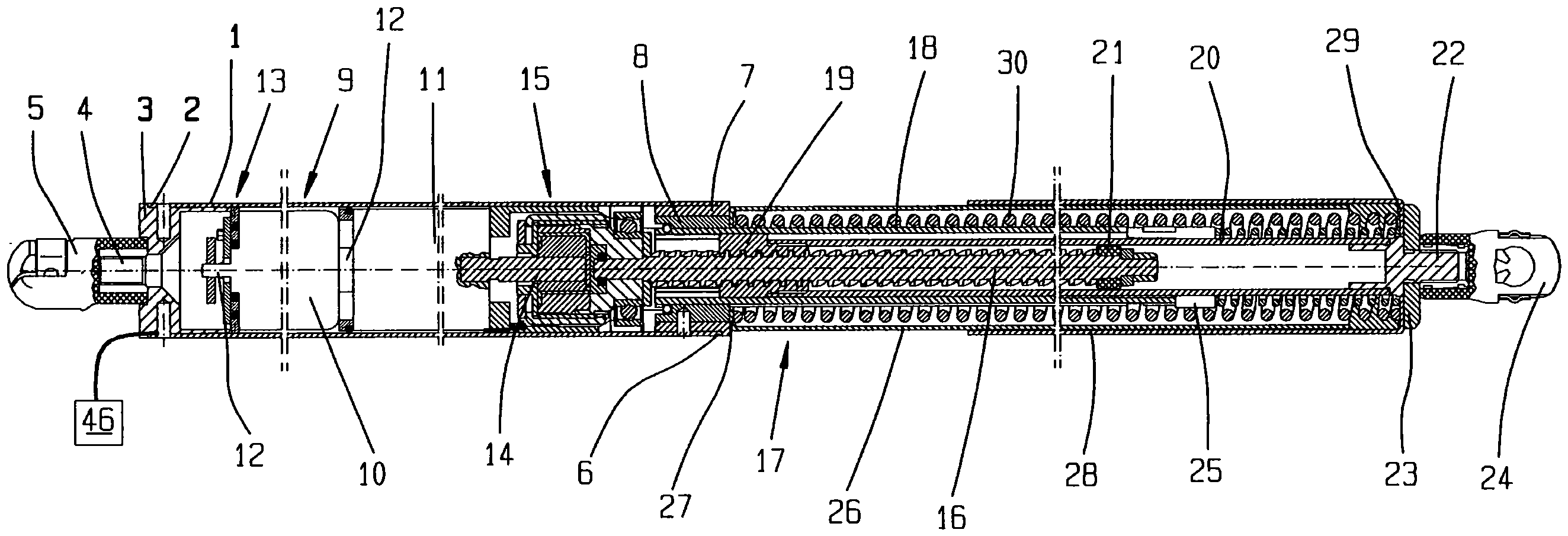
Die in
Nahe dem ersten Ende 2 des ersten Gehäuserohrs 1 ist ein Drehantrieb 9 angeordnet, der einen Elektromotor 10 und ein Getriebe 11 umfasst. Aus beiden Stirnseiten des Elektromotors 10 ragt eine Antriebswelle 12 heraus, die einerseits eine Sensoreinrichtung 13 und andererseits das Getriebe 11 antreibt. Auf der dem Elektromotor 10 gegenüberliegenden Seite des Getriebes 11 erstreckt sich eine Getriebeausgangswelle 14 in Richtung zweites Ende 6. Eine Kupplungseinrichtung 15 ist einerseits mit der Getriebeausgangswelle 14 und andererseits mit einer sich durch die Führungsbuchse 8 erstreckenden Gewindespindel 16 eines Spindeltriebs 17 verbunden. Durch die Führungsbuchse 8 erstreckt sich ferner ein die Gewindespindel 16 koaxial umgebendes Führungsrohr 18.Near the
Auf der Gewindespindel 16 ist eine Spindelmutter 19 angeordnet, die axial verschiebbar, jedoch verdrehsicher in dem Führungsrohr 18 geführt wird. Die Spindelmutter 19 ist mit einem Ende eines die Gewindespindel 16 koaxial umschließenden Spindelrohrs 20 verbunden, in dem die Gewindespindel 16 an ihrem der Kupplungseinrichtung 15 entgegengesetzten Ende mittels einer Spindelführung 21 geführt ist, um Radialbewegungen der Gewindespindel 16 zu verhindern. An dem der Spindelmutter 19 gegenüberliegenden Ende ist ein Gewindebolzen 22 an dem Führungsrohr 18 angeordnet, auf den wiederum eine Abstützscheibe 23 aufgesteckt ist, die mit einer zweiten Befestigungsvorrichtung 24 in Form einer weiteren Kugelpfanne an dem Gewindebolzen 22 fixiert ist.On the threaded
An dem Ende des Führungsrohrs 18, welches dem in der Führungsbuchse 8 ruhenden Ende gegenüberliegt, ist eine Führungsbuchse 25 angeordnet, welche das Spindelrohr 20 in axialer Richtung verschiebbar führt. Das Führungsrohr 18 wird koaxial von einem zweiten Gehäuserohr 26 umgeben, wobei sich das zweite Gehäuserohr 26 mit einem Innenflansch 27 an dem zweiten Ende 6 des ersten Gehäuserohrs 1 bzw. an der Führungsbuchse 8 oder der Hülse 7 abstützt.At the end of the
Das zweite Gehäuserohr 26 ist wiederum wenigstens teilweise von einem Überrohr 28 umgeben. Das Überrohr 28 weist einen Innenflansch 29 auf, der an der Abstützscheibe 23 anliegt.The
Um die Ausfahrbewegung der Antriebseinrichtung zu unterstützen, ist zwischen dem Führungsrohr 18 und dem zweiten Gehäuserohr 26 bzw. dem Überrohr 28 eine Schraubendruckfeder 30 angeordnet, welche sich am Innenflansch 27 des zweiten Gehäuserohrs 26 und dem Innenflansch 29 des Überrohrs 28 abstützt.In order to support the extension movement of the drive device, a
Die
Die Kupplungseinrichtung 15 ist zwischen dem Getriebe 11 und einem Spindellager 31 angeordnet. Die Kupplungseinrichtung 15 umfasst ein Innenteil 32, ein Dämpfungselement 33, ein Zwischenteil 34, ein Federring 35 und einem Außenteil 36. Andere Positionen der Kupplungseinrichtung im Antriebsstrang und ein anderer Aufbau der Kupplung, beispielsweise mit Reibscheiben sind jedoch auch möglich.The
Die Getriebeausgangswelle 14 ist mittels einer form- oder kraftschlüssigen Verbindung, beispielsweise eine Kerbverzahnung, zur Drehmomentübertragung mit dem Innenteil 32 steckbar verbunden. Das Innenteil 32 bildet mit dem Dämpfungselement 33 und dem Zwischenteil 34 eine Art elastische Klauenkupplung.The
Das Zwischenteil 34 ist über den Federring 35 mit dem Außenteil 36 verbunden. Der Federring 35 ist in dem Außenteil 36 in axialer und in radialer Richtung fixiert.The
Die Verbindung des Federringes 35 zum Zwischenteil 34, erfolgt über mehrere, nicht gezeigte radial angeordnete Federarme, die in radial umlaufende wellenartige oder ebenfalls nicht dargestellte dreieckförmige Mulden an der Außenmantelfläche des Zwischenteils 34 eingreifen.The connection of the
Die Übertragung des Drehmomentes erfolgt über die Getriebeausgangswelle 14, das Innenteil 32, das Dämpfungselement 33, das Zwischenteil 34 und den Federring 35 in das Außenteil 36 der Kupplungseinrichtung 15.The torque is transmitted via the
Dabei erfolgt die Übertragung des Drehmoments zwischen dem Federring 35 und dem Zwischenteil 34 über die Enden der Federarme. Ab einem gewissen Drehmoment wird das Zwischenteil 34 relativ zum Federring 35 verdreht, wobei, wenn sich das Zwischenteil weiter dreht, die Federarme über die Enden zuerst radial nach außen gedrückt werden und sich anschließend wieder zurück biegen, wobei die Enden in die nächste Mulde einrasten.The torque is transmitted between the
Die Kupplungseinrichtung 15 ist radial und axial in dem Spindellager 31 gelagert. Dazu ist, wie in
Das in Richtung Getriebe 11 weisende Ende des Außenteils 36 ist, einen Flansch 40 bildend, nach innen gebördelt und hält eine Scheibe 41 eines Tragelements in einer Position zwischen einerseits Innenteil 32, Dämpfungselement 33, Zwischenteil 34 und Federring 35 und andererseits Flansch 40. Von der Scheibe 41 erstreckt sich weiter in Richtung Getriebe 11 eine einstückig mit der Scheibe 41 verbundene Hülse 42. Auf der Hülse 42 ist ein mehrere Nord- und Südpole aufweisender Magnetring 43 angebracht. Der Magnetring 43 wirkt mit einem Sensorelement 44 zusammen, der auf einer Platine 45 angeordnet ist. Die Platine 45 ist wiederum an einer Innenwand eines Gehäuses der Kupplungseinrichtung 15 angeordnet.The end of the
Das Sensorelement 44 umfasst wenigstens einen Hallsensor, vorzugsweise jedoch zwei Hallsensoren mit einem definierten Phasenversatz. Obwohl hier als ein Bauteil dargestellt, ist es jedoch auch möglich, dass zwei getrennte Hallsensoren verwendet werden können.The
Wird das bewegbare Teil, beispielsweise die Klappe eines Kraftfahrzeugs bei deaktivierter oder „schlafender“ Steuereinrichtung 46 manuell betätigt, wird durch ein Signal des Hallsensors oder beider Hallsensoren die Steuereinrichtung 46 über nur angedeutete Leitungen eingeschaltet, wodurch die Drehbewegung der Gewindespindel 16 über das mit der Gewindespindel 16 drehgesichert verbundene Außenteil 36 der Kupplungseinrichtung 15 und dem ebenfalls drehgesichert mit dem Außenteil 36 verbundenen Magnetring 43 sensiert wird.If the movable part, for example the flap of a motor vehicle, is manually operated when the
Claims (2)
Priority Applications (4)
| Application Number | Priority Date | Filing Date | Title |
|---|---|---|---|
| DE102010053226.6A DE102010053226B4 (en) | 2010-12-03 | 2010-12-03 | drive device |
| US13/310,188 US8601891B2 (en) | 2010-12-03 | 2011-12-02 | Driving device |
| CN201110394997.XA CN102561875B (en) | 2010-12-03 | 2011-12-02 | Driving device |
| JP2011264855A JP5447998B2 (en) | 2010-12-03 | 2011-12-02 | Drive device |
Applications Claiming Priority (1)
| Application Number | Priority Date | Filing Date | Title |
|---|---|---|---|
| DE102010053226.6A DE102010053226B4 (en) | 2010-12-03 | 2010-12-03 | drive device |
Publications (2)
| Publication Number | Publication Date |
|---|---|
| DE102010053226A1 DE102010053226A1 (en) | 2012-06-06 |
| DE102010053226B4 true DE102010053226B4 (en) | 2025-04-17 |
Family
ID=46082780
Family Applications (1)
| Application Number | Title | Priority Date | Filing Date |
|---|---|---|---|
| DE102010053226.6A Active DE102010053226B4 (en) | 2010-12-03 | 2010-12-03 | drive device |
Country Status (4)
| Country | Link |
|---|---|
| US (1) | US8601891B2 (en) |
| JP (1) | JP5447998B2 (en) |
| CN (1) | CN102561875B (en) |
| DE (1) | DE102010053226B4 (en) |
Families Citing this family (26)
| Publication number | Priority date | Publication date | Assignee | Title |
|---|---|---|---|---|
| DE102010019344B3 (en) * | 2010-05-05 | 2011-05-19 | Stabilus Gmbh | Drive devices for flap of vehicle, have housing part that is connected with fixed base part or with movable component |
| US8413532B2 (en) * | 2010-06-15 | 2013-04-09 | Timotion Technology Co. Ltd. | Safety release mechanism for linear actuator |
| DE102012024375A1 (en) * | 2012-12-13 | 2014-06-18 | Kiekert Aktiengesellschaft | Device and method for actuating a motor vehicle locking device |
| US9821774B1 (en) * | 2013-03-04 | 2017-11-21 | Craig Alan Searer | Method and apparatus for jackscrew with integral drive nut grease fitting |
| DE102013003830B4 (en) * | 2013-03-07 | 2026-02-05 | Brose Fahrzeugteile Se & Co. Kommanditgesellschaft, Bamberg | Spindle drive for an adjustment element of a motor vehicle |
| JP2015105490A (en) * | 2013-11-29 | 2015-06-08 | アイシン精機株式会社 | Resistance generator |
| US9103373B1 (en) | 2014-04-30 | 2015-08-11 | Hi-Lex Controls, Inc. | Bearing-shaft assembly with bearing and method of attaching a bearing to a shaft |
| DE102014111921A1 (en) * | 2014-08-20 | 2016-02-25 | Stabilus Gmbh | Adjustment system for adjusting a component of a motor vehicle on an adjustment path |
| CN105275301B (en) * | 2015-07-22 | 2016-12-07 | 上海蒙芭蒂实业有限公司 | Electric gas spring support rod for automobile back door |
| US10100568B2 (en) | 2015-08-12 | 2018-10-16 | Magna Closures Inc. | Electromechanical strut with lateral support feature |
| JP2017065518A (en) * | 2015-09-30 | 2017-04-06 | アイシン精機株式会社 | Vehicle door opening and closing device |
| CN106761138B (en) * | 2016-12-30 | 2019-07-23 | 安徽沃杰斯汽车科技有限公司 | A kind of automobile power back door strut |
| CN106761141B (en) * | 2017-03-07 | 2019-03-26 | 上海胜华波汽车电器有限公司 | Electronic strut with overload protection function |
| DE102017212823A1 (en) * | 2017-07-26 | 2019-01-31 | Stabilus Gmbh | Spindle drive means |
| KR101927488B1 (en) * | 2017-09-07 | 2018-12-11 | 주식회사 한화 | Linear actuator having free fall operation |
| CN107829637A (en) * | 2017-11-30 | 2018-03-23 | 无锡典聚科技有限公司 | A kind of electric tail gate strut spring guide spline structure |
| DE102017131058A1 (en) * | 2017-12-22 | 2019-06-27 | Stabilus Gmbh | Flap assembly for a vehicle |
| DE102019117540A1 (en) * | 2019-06-28 | 2020-12-31 | Kiekert Aktiengesellschaft | Electromotive drive for automotive applications |
| DE102020104212A1 (en) * | 2020-02-18 | 2021-08-19 | Brose Fahrzeugteile Se & Co. Kommanditgesellschaft, Bamberg | Drive arrangement for motorized adjustment of an adjusting element of a motor vehicle |
| DE102021117395A1 (en) * | 2020-07-27 | 2022-01-27 | Magna Closures Inc. | POWER OPERATING UNIT FOR POWERED DOOR WITH A MECHANICALLY OPERATED CLUTCH/BRAKE UNIT |
| DE102020132508B4 (en) * | 2020-08-11 | 2022-04-14 | Stabilus Gmbh | Drive device for moving a closure element of a motor vehicle |
| DE102020134289A1 (en) | 2020-12-18 | 2022-06-23 | Edscha Engineering Gmbh | Spindle rod for a spindle device and method for manufacturing a spindle rod for a spindle device |
| US11661783B1 (en) * | 2022-03-01 | 2023-05-30 | Hsin Chong Machinery Works Co. Ltd. | Electric support rod |
| CN114837513B (en) * | 2022-05-06 | 2023-11-21 | 浙江久易电子科技股份有限公司 | Door operator and control circuit thereof |
| DE102023100688A1 (en) * | 2023-01-12 | 2024-07-18 | Edscha Mechatronics Solutions GmbH | Drive device for a vehicle door |
| DE102024129877B3 (en) | 2024-10-15 | 2025-12-11 | Edscha Mechatronics Solutions GmbH | Actuator |
Citations (1)
| Publication number | Priority date | Publication date | Assignee | Title |
|---|---|---|---|---|
| DE102005030052A1 (en) | 2005-06-27 | 2006-12-28 | Stabilus Gmbh | Drive device for e.g. lid of vehicle has threaded spindle with its end stored swivelably at housing tube and is axially stationary compared to housing tube as well as can be swivelably driven by rotary drive |
Family Cites Families (31)
| Publication number | Priority date | Publication date | Assignee | Title |
|---|---|---|---|---|
| US2824460A (en) * | 1954-11-24 | 1958-02-25 | Foxboro Co | Magnetic reversible nut |
| NL7003056A (en) * | 1970-03-04 | 1971-09-07 | ||
| ES2042077T3 (en) * | 1990-01-12 | 1993-12-01 | Gunter Horst Rohm | PROCEDURE TO GENERATE A FORCE OF ADJUSTMENT FOR THE CLAMPING MEMBERS OF A CLAMPING EQUIPMENT. |
| US5131510A (en) * | 1990-07-30 | 1992-07-21 | General Electric Company | Brake assembly for a control rod drive |
| JPH05104950A (en) * | 1991-10-18 | 1993-04-27 | Nissan Motor Co Ltd | Vehicle door opening/closing control device |
| US5355743A (en) * | 1991-12-19 | 1994-10-18 | The University Of Texas At Austin | Robot and robot actuator module therefor |
| US5673593A (en) * | 1995-12-14 | 1997-10-07 | Joerns Healthcare, Inc. | Overrunning nut for linear actuator |
| US5793574A (en) * | 1996-09-10 | 1998-08-11 | Quantum Corporation | Tape head actuator assembly having a shock suppression sleeve |
| JP2001086701A (en) * | 1999-09-16 | 2001-03-30 | Asmo Co Ltd | Motor-driven actuator |
| US6879065B2 (en) * | 2001-04-10 | 2005-04-12 | International Business Machines Corporation | Linear actuator |
| US6717324B2 (en) * | 2001-10-15 | 2004-04-06 | Ming Yan Chen | Magnet motor device |
| WO2003039899A2 (en) * | 2001-11-05 | 2003-05-15 | Continental Teves Ag & Co. Ohg | Device with additional restoring force on the gas pedal based on the deviation of a vehicle parameter from the set value |
| JP4182726B2 (en) * | 2002-02-20 | 2008-11-19 | 日本精工株式会社 | Linear actuator |
| ITMI20032000A1 (en) * | 2003-10-16 | 2005-04-17 | Univer Spa | ELECTRIC CYLINDER |
| US6952165B2 (en) * | 2003-12-19 | 2005-10-04 | Honeywell International, Inc. | Concealed wireless sensor with external antenna |
| US20070162152A1 (en) * | 2005-03-31 | 2007-07-12 | Massachusetts Institute Of Technology | Artificial joints using agonist-antagonist actuators |
| US7551411B2 (en) * | 2005-10-12 | 2009-06-23 | Black & Decker Inc. | Control and protection methodologies for a motor control module |
| US8457836B2 (en) * | 2006-03-23 | 2013-06-04 | Mitchell Gabriel Mircea Balasu | Systems for announcing the health of aircraft control elements |
| US7680565B2 (en) * | 2006-03-23 | 2010-03-16 | Mitchell Gabriel Mircea Balasu | Systems for announcing the health of ball screw actuators and ball recirculation |
| EP1840311A1 (en) * | 2006-03-31 | 2007-10-03 | Valeo Sicherheitssysteme GmbH | Adjusting device having a spindle drive |
| DE102006030986B4 (en) * | 2006-07-03 | 2012-01-19 | Edscha Engineering Gmbh | Device and method for controlling a vehicle door or a vehicle door |
| US7743683B2 (en) * | 2006-08-15 | 2010-06-29 | Umagination Labs, L.P. | Systems and methods of a power tool system with interchangeable functional attachments powered by a direct rotational drive |
| US8931682B2 (en) * | 2007-06-04 | 2015-01-13 | Ethicon Endo-Surgery, Inc. | Robotically-controlled shaft based rotary drive systems for surgical instruments |
| US8789413B2 (en) * | 2007-09-21 | 2014-07-29 | Romet Limited | Unidirectional clutch assembly |
| DE102007059564C5 (en) * | 2007-12-11 | 2014-04-24 | Stabilus Gmbh | driving means |
| CN101983297B (en) * | 2008-03-27 | 2015-01-07 | 麦克森发电机股份公司 | Dual Differential Semi-Active Actuator for Interactive Work and Fast Movement |
| DE102008031228B4 (en) * | 2008-07-03 | 2013-07-18 | Stabilus Gmbh | driving means |
| DE102009011184B4 (en) * | 2009-01-28 | 2015-06-03 | Stabilus Gmbh | driving means |
| FR2943089B1 (en) * | 2009-03-10 | 2016-11-25 | Soc Innovation Du Batiment | MODULE FOR CONTROLLING A GREENHOUSE OPENING |
| US8960031B2 (en) * | 2009-09-01 | 2015-02-24 | Parker-Hannifin Corporation | Aircraft stabilizer actuator |
| KR101939267B1 (en) * | 2010-07-21 | 2019-01-16 | 삼성전자주식회사 | Method and device for measuring dose in injector |
-
2010
- 2010-12-03 DE DE102010053226.6A patent/DE102010053226B4/en active Active
-
2011
- 2011-12-02 JP JP2011264855A patent/JP5447998B2/en not_active Expired - Fee Related
- 2011-12-02 CN CN201110394997.XA patent/CN102561875B/en active Active
- 2011-12-02 US US13/310,188 patent/US8601891B2/en not_active Expired - Fee Related
Patent Citations (1)
| Publication number | Priority date | Publication date | Assignee | Title |
|---|---|---|---|---|
| DE102005030052A1 (en) | 2005-06-27 | 2006-12-28 | Stabilus Gmbh | Drive device for e.g. lid of vehicle has threaded spindle with its end stored swivelably at housing tube and is axially stationary compared to housing tube as well as can be swivelably driven by rotary drive |
Also Published As
| Publication number | Publication date |
|---|---|
| JP2012117673A (en) | 2012-06-21 |
| DE102010053226A1 (en) | 2012-06-06 |
| US8601891B2 (en) | 2013-12-10 |
| US20120137803A1 (en) | 2012-06-07 |
| CN102561875B (en) | 2015-04-29 |
| CN102561875A (en) | 2012-07-11 |
| JP5447998B2 (en) | 2014-03-19 |
Similar Documents
| Publication | Publication Date | Title |
|---|---|---|
| DE102010053226B4 (en) | drive device | |
| DE102009011184B4 (en) | driving means | |
| DE102012110505B4 (en) | driving means | |
| DE102007020826B4 (en) | driving means | |
| DE102013108031B4 (en) | Actuator with position detection mechanism | |
| DE102013106000B4 (en) | Drive with quick-release mechanism | |
| EP2457754B1 (en) | Suspension actuator | |
| DE102008008790B4 (en) | Antriebsseinrichtung | |
| DE102008008294B4 (en) | driving means | |
| EP1881235A2 (en) | Powered spindle drive for a moveable part | |
| DE102013112813A1 (en) | Sensor device and disc brake with a sensor device | |
| EP4130515B1 (en) | Driving device for an adjustable vehicle door | |
| DE102015220920B4 (en) | Assembly with a friction device | |
| DE102006042023A1 (en) | driving means | |
| DE102007039823B4 (en) | driving means | |
| DE102006042100B3 (en) | driving means | |
| DE102006000746A1 (en) | Adjustable free-wheel for motor vehicle, has outer ring and blocking device cage designed as rotor and stator, where cage has coils so that cage is rotatable with respect to ring in switched-on and off-position by energizing coils | |
| DE102013016289B4 (en) | Adjustment drive, in particular height adjustment drive, of a vehicle seat with a safety gear | |
| DE102007008983B4 (en) | Device for tolerance compensation for a coupling | |
| DE102006042458B4 (en) | driving means | |
| DE102006041660B4 (en) | Adjusting device for the linear adjustment of an actuator | |
| DE102014002629A1 (en) | System for adjusting a bearing arrangement for a transmission with a tool | |
| DE102007043196B4 (en) | Coupling device for emergency operation of a parking brake | |
| DE102008017458A1 (en) | Torsional vibration damper, particularly for drive train of vehicle, has primary side and secondary side rotating around rotational axis with respect to primary side against actions of damper spring assembly | |
| DE20109710U1 (en) | Parking brake device for motor vehicles |
Legal Events
| Date | Code | Title | Description |
|---|---|---|---|
| R012 | Request for examination validly filed | ||
| R016 | Response to examination communication | ||
| R082 | Change of representative | ||
| R016 | Response to examination communication | ||
| R018 | Grant decision by examination section/examining division |