DE102010049994B3 - Resist structure for producing an X-ray optical lattice structure - Google Patents
Resist structure for producing an X-ray optical lattice structure Download PDFInfo
- Publication number
- DE102010049994B3 DE102010049994B3 DE102010049994A DE102010049994A DE102010049994B3 DE 102010049994 B3 DE102010049994 B3 DE 102010049994B3 DE 102010049994 A DE102010049994 A DE 102010049994A DE 102010049994 A DE102010049994 A DE 102010049994A DE 102010049994 B3 DE102010049994 B3 DE 102010049994B3
- Authority
- DE
- Germany
- Prior art keywords
- ray optical
- resist
- producing
- optical grating
- stabilizing
- Prior art date
- Legal status (The legal status is an assumption and is not a legal conclusion. Google has not performed a legal analysis and makes no representation as to the accuracy of the status listed.)
- Expired - Fee Related
Links
- 230000003287 optical effect Effects 0.000 title claims abstract description 20
- 230000000087 stabilizing effect Effects 0.000 claims abstract description 21
- 239000000758 substrate Substances 0.000 claims abstract description 6
- 239000000463 material Substances 0.000 claims description 4
- 229920002120 photoresistant polymer Polymers 0.000 claims 1
- 238000004519 manufacturing process Methods 0.000 abstract description 8
- PCHJSUWPFVWCPO-UHFFFAOYSA-N gold Chemical compound [Au] PCHJSUWPFVWCPO-UHFFFAOYSA-N 0.000 abstract description 5
- 239000010931 gold Substances 0.000 abstract description 5
- 229910052737 gold Inorganic materials 0.000 abstract description 5
- 238000005452 bending Methods 0.000 abstract description 3
- 230000000694 effects Effects 0.000 abstract description 3
- 230000002411 adverse Effects 0.000 abstract description 2
- 238000003384 imaging method Methods 0.000 description 7
- 238000010521 absorption reaction Methods 0.000 description 3
- 238000000034 method Methods 0.000 description 2
- 238000001015 X-ray lithography Methods 0.000 description 1
- 230000002745 absorbent Effects 0.000 description 1
- 239000002250 absorbent Substances 0.000 description 1
- 238000004458 analytical method Methods 0.000 description 1
- 230000001427 coherent effect Effects 0.000 description 1
- 238000010327 methods by industry Methods 0.000 description 1
- 230000005855 radiation Effects 0.000 description 1
- 230000006641 stabilisation Effects 0.000 description 1
- 238000011105 stabilization Methods 0.000 description 1
Images

Classifications
-
- G—PHYSICS
- G21—NUCLEAR PHYSICS; NUCLEAR ENGINEERING
- G21K—TECHNIQUES FOR HANDLING PARTICLES OR IONISING RADIATION NOT OTHERWISE PROVIDED FOR; IRRADIATION DEVICES; GAMMA RAY OR X-RAY MICROSCOPES
- G21K1/00—Arrangements for handling particles or ionising radiation, e.g. focusing or moderating
- G21K1/06—Arrangements for handling particles or ionising radiation, e.g. focusing or moderating using diffraction, refraction or reflection, e.g. monochromators
-
- G—PHYSICS
- G21—NUCLEAR PHYSICS; NUCLEAR ENGINEERING
- G21K—TECHNIQUES FOR HANDLING PARTICLES OR IONISING RADIATION NOT OTHERWISE PROVIDED FOR; IRRADIATION DEVICES; GAMMA RAY OR X-RAY MICROSCOPES
- G21K2207/00—Particular details of imaging devices or methods using ionizing electromagnetic radiation such as X-rays or gamma rays
- G21K2207/005—Methods and devices obtaining contrast from non-absorbing interaction of the radiation with matter, e.g. phase contrast
Landscapes
- Physics & Mathematics (AREA)
- Spectroscopy & Molecular Physics (AREA)
- Engineering & Computer Science (AREA)
- General Engineering & Computer Science (AREA)
- High Energy & Nuclear Physics (AREA)
- Diffracting Gratings Or Hologram Optical Elements (AREA)
Abstract
Die vorliegende Erfindung betrifft eine Resiststruktur zur Herstellung einer röntgenoptischen Gitterstruktur. Die Erfindung umfasst stabilisierende Balken, die in die Resiststruktur eingebracht werden. Dabei sind die Stege der Resisstruktur mit einem ersten Winkel α auf einem Substrat angebracht und die stabilisierenden Balken mit einem zweiten Winkel β, wobei zwischen α und β mindestens ein Abstand von 20° bestehen muss und höchstens ein Abstand von 70° bestehen darf, um die stabilisierende Wirkung zu erhalten. Insbesondere soll die Herstellung von röntgenoptischen Gitterstrukturen mit Aspektverhältnissen von über 500 ermöglicht werden, ohne dass sich die Gitterstege verbiegen, oder sich die stabiliserende Struktur nachteilig auf die Visibility auswirkt. Die Resiststrukturen eignen sich besonders zur Herstellung röntgenoptischer Gitterstrukturen aus Gold.The present invention relates to a resist pattern for producing an X-ray optical grating structure. The invention includes stabilizing beams that are incorporated into the resist pattern. The webs of the Resisstruktur at a first angle α are mounted on a substrate and the stabilizing beams at a second angle β, wherein between α and β must be at least a distance of 20 ° and at most a distance of 70 ° may exist to the to obtain stabilizing effect. In particular, the production of X-ray optical grating structures with aspect ratios of more than 500 is to be made possible without the grid bars bending, or the stabilizing structure has an adverse effect on the visibility. The resist structures are particularly suitable for the production of X-ray optical grating structures made of gold.
Description
Die vorliegende Erfindung betrifft eine Resiststruktur zur Herstellung einer röntgenoptischen Gitterstruktur.The present invention relates to a resist pattern for producing an X-ray optical grating structure.
Für viele Anwendungen, wie beispielsweise in der medizinischen Diagnostik oder der Materialanalyse wird Röntgenstrahlung eingesetzt. Dabei kommen optische Gitter zum Einsatz an deren Struktur und insbesondere an deren Aspektverhältnis besondere Anforderungen gestellt werden, da die Qualität der in der Fachsprache als differentielles Phasen-Kontrast-Imaging (DPCI) bezeichneten Bildgebungsmethode mit Röntgenstrahlung entscheidend von der Höhe der optischen Gitterstrukturen abhängt.For many applications, such as in medical diagnostics or material analysis, X-rays are used. Here, optical gratings are used whose structure and in particular their aspect ratio special requirements are made, since the quality of the imaging technique referred to in the jargon as differential phase contrast imaging (DPCI) with X-ray depends decisively on the height of the optical grating structures.
Um einen für medizintechnische Anwendungen relevanten hohen Kontrast zur erzielen, sollte die Absorption des in der Resiststruktur, in den Stegspalten abgeschiedenen Materials (in der Regel Gold) im Bereich größer als 80% liegen. Bei röntgentomographischen Untersuchungen mit Röntgenröhren liegen die Röntgenenergien, für die der tomografische Aufbau optimal ausgelegt ist und in der Fachsprache als Designenergien bezeichnet werden, je nach Anwendung im Bereich von 20 keV bis 60 keV, wobei durch die polychromatische Strahlung der Röntgenröhre auch Energien bis zu etwa 10 keV oberhalb der Designenergie vorhanden sind. Dies bedeutet, dass die Dicke des absorbierenden Goldes mindestens 100 μm und damit die Höhe der Resiststruktur auch über 100 μm betragen muss.In order to achieve a high contrast relevant for medical applications, the absorption of the material deposited in the resist structure, in the web gaps (usually gold) in the range should be greater than 80%. Depending on the application, X-ray energies, for which the tomographic structure is optimally designed and termed design energies, are in the range from 20 keV to 60 keV, with the polychromatic radiation of the x-ray tube also carrying energies up to about 10 keV above the design energy are present. This means that the thickness of the absorbing gold must be at least 100 microns and thus the height of the resist structure over 100 microns.
Aus dem Stand der Technik sind Verfahren bekannt, um Resiststrukturen mit Höhen von mehreren hundert Mikrometern herzustellen. In F. Pfeiffer et al., Nature Physics (2006) Advanced Online Publication, p. l werden die Möglichkeiten der Phasenkontrast-Röntgenbildgebung mit nicht-kohärenten Röntgenquellen beschrieben. Zur Realisierung dieser Bildgebungssysteme ist die Herstellung von Gitterstrukturen mit hohem Aspektverhältnis notwendig. Diese Anforderungen an die Dimensionen der absorbierenden Strukturen, sowie deren mechanische Stabilität stellen jedoch prozesstechnische Probleme dar.Methods are known in the art for producing resist structures with heights of several hundred microns. In F. Pfeiffer et al., Nature Physics (2006) Advanced Online Publication, p. The possibilities of phase-contrast X-ray imaging with non-coherent X-ray sources are described. For the realization of these imaging systems, the production of lattice structures with a high aspect ratio is necessary. However, these demands on the dimensions of the absorbent structures, as well as their mechanical stability represent process engineering problems.
In E. Reznikova et al., Soft X-ray lithography of high aspect ratio SU8 submicron structures, Micro Syst. Techn. (2008) wird ein Verfahren beschrieben, das prinzipiell die Herstellung derartiger Strukturen erlaubt. In der Veröffentlichung wird aber auch deutlich, dass es bei Strukturhöhen von größer 60 μm zu einer Verbiegung der unterschiedlich lang gewählten Stege kommt und somit das Aspektverhältnis begrenzt ist.In E. Reznikova et al., Soft X-ray lithography of high aspect ratio SU8 submicron structures, Micro Syst. Techn. (2008) a method is described, which in principle allows the production of such structures. In the publication, however, it is also clear that at structural heights of greater than 60 μm, the webs of different lengths are bent and thus the aspect ratio is limited.
In J. Kenntner, et al., Front- and backside structuring of gratings for Phase contrast imaging with x-ray tubes, Proc. SPIE, Vol. 7804, 780408 (2010), werden Resiststrukturen gezeigt, mit denen versucht wurde, das Problem der Verbiegung der Gitterstege dadurch zu verhindern, dass die Gitterstege durch Füllbalken verbunden werden. Der Nachteil dieser Lösung ist, dass die Goldstege immer wieder durch quasi transparente Bereiche (Füllbalken) unterbrochen werden. Dies führt bei der Analyse der Visibility V mit einem Detektor, der eine Pixelgröße im Bereich weniger Gitterperioden und kleiner hat, zu schwankenden Visibility-Werten. Die Visibility V ist wie folgt definiert
Ausgehend davon liegt die Aufgabe der Erfindung darin, eine Resiststruktur zur Herstellung einer röntgenoptischen Gitterstruktur vorzuschlagen, die die aufgeführten Nachteile und Einschränkungen vermeidet. Insbesondere soll die Herstellung von röntgenoptischen Gitterstrukturen mit Aspektverhältnissen von über 500 ermöglicht werden, ohne dass sich die Gitterstege verbiegen, oder sich die stabiliserende Struktur nachteilig auf die Visibility auswirkt.Proceeding from this, the object of the invention is to propose a resist structure for producing a roentgen optical lattice structure which avoids the disadvantages and limitations listed. In particular, the production of X-ray optical grating structures with aspect ratios of more than 500 is to be made possible without the grid bars bending, or the stabilizing structure has an adverse effect on the visibility.
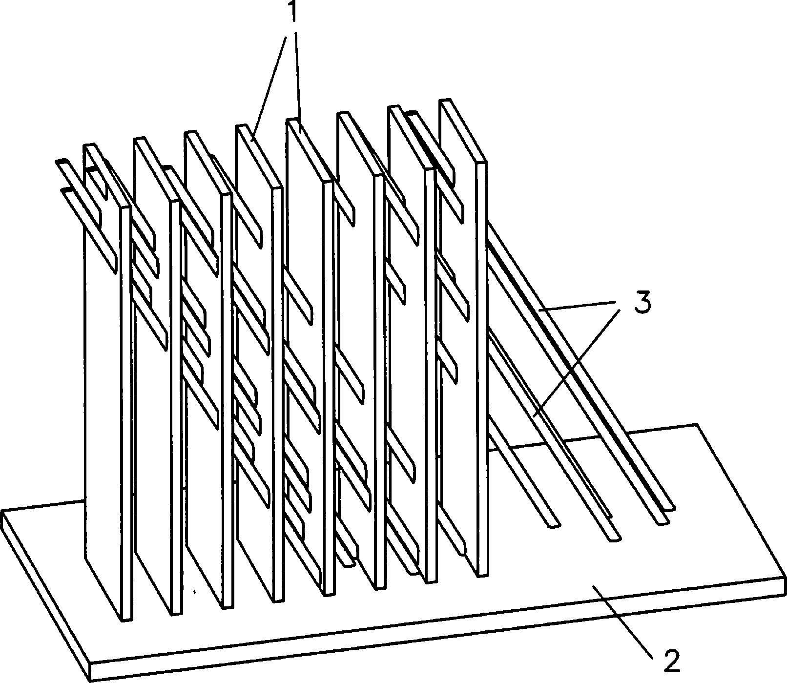
Die Erfindung beruht auf dem Grundgedanken, dass stabilisierende Balken in die Resiststruktur eingebracht werden. Dabei sind die Stege der Resisstruktur mit einem ersten Winkel α auf dem Substrat angebracht und die stabilisierenden Balken mit einem zweiten Winkel β, wobei zwischen α und β mindestens ein Abstand von 20° bestehen muss und höchstens ein Abstand von 70° bestehen darf, um die stabilisierende Wirkung zu erhalten.The invention is based on the idea that stabilizing beams are introduced into the resist structure. The webs of the Resisstruktur are attached at a first angle α on the substrate and the stabilizing beam with a second angle β, wherein between α and β must be at least a distance of 20 ° and at most a distance of 70 ° may exist to the to obtain stabilizing effect.
Derartige Resiststrukturen eignen sich für die Herstellung von röntgenoptischen Gitterstrukturen. Im Bereich des stabilisierenden Balkens wird die Höhe des in den Stegspalten abgeschiedenen Materials maximal um den Wert d' vermindert, der sich aus
Mit derartigen Strukturen können Gitter für die Phasenkontrast-Röntgenbildgebung in beliebiger Höhe mit annähernd konstanter Visibility über der gesamten Fläche der Gitterstruktur realisiert werden. Damit sind auch für Energien über 40 keV Strukturen realisierbar, die eine Absorption von 80% und mehr aufweisen. Dies und die Gleichmäßigkeit der Absorption ermöglicht dabei eine weit bessere Auflösung im Phasenkontrastbild.With such structures, gratings for phase-contrast X-ray imaging of any height can be realized with approximately constant visibility over the entire area of the grating structure. This makes it possible to realize structures with energies of more than 40 keV, which have an absorption of 80% and more. This and the uniformity of the absorption allows a much better resolution in the phase contrast image.
Die eingangs beschriebenen Resiststrukturen eignen sich aufgrund ihrer hohen Aspektverhältnisse auch für die Herstellung von Gittern zur Neutronenbildgebung.The resist structures described above are also suitable for the production of gratings for neutron imaging because of their high aspect ratios.
Nachfolgend wird die Erfindung anhand von Beispielen und der Figur näher erläutert.The invention will be explained in more detail by means of examples and the figure.
Der Abstand zwischen zwei benachbarten stabilisierenden Balken muss für jede Richtung im Bereich zwischen der doppelten und der 20-fachen Spaltbreite liegen, wobei der Umkreisdurchmesser eines jeden Balkens zwischen 1 μm und 10 μm betragen muss. Bevorzugt beträgt der Balkenumkreisdurchmesser 2 μm bis 5 μm. Eine derartige Anordnung und Dimensionierung der Balken sowie die Wahl der Winkel bewirkt, dass in einem Stegspalt der Resiststruktur und damit in den späteren Stegen der Gitterstruktur, die Gesamthöhe der stabilisierenden Balken maximal 20% der Gitterhöhe und bevorzugt maximal 10% der Gitterhöhe beträgt und somit die Visibility nur gering beeinflusst.The distance between two adjacent stabilizing beams must be in the range between double and 20 times the gap width for each direction, with the perimeter diameter of each beam between 1 μm and 10 μm. The beam circumference diameter is preferably 2 μm to 5 μm. Such an arrangement and dimensioning of the beams and the choice of the angle causes that in a web gap of the resist structure and thus in the later webs of the lattice structure, the total height of the stabilizing beams a maximum of 20% of the grid height and preferably at most 10% of the grid height and thus the Visibility only slightly influenced.
Die im Beispiel erläuterten Resiststrukturen eignen sich besonders zur Herstellung röntgenoptischer Gitterstrukturen aus Gold.The resist structures explained in the example are particularly suitable for the production of X-ray optical grating structures made of gold.
Claims (9)
Priority Applications (3)
| Application Number | Priority Date | Filing Date | Title |
|---|---|---|---|
| DE102010049994A DE102010049994B3 (en) | 2010-10-28 | 2010-10-28 | Resist structure for producing an X-ray optical lattice structure |
| EP11770377.7A EP2633528B1 (en) | 2010-10-28 | 2011-10-13 | Resist structure for producing an x-ray optical grating structure |
| PCT/EP2011/005141 WO2012055495A1 (en) | 2010-10-28 | 2011-10-13 | Resist structure for producing an x-ray optical grating structure |
Applications Claiming Priority (1)
| Application Number | Priority Date | Filing Date | Title |
|---|---|---|---|
| DE102010049994A DE102010049994B3 (en) | 2010-10-28 | 2010-10-28 | Resist structure for producing an X-ray optical lattice structure |
Publications (1)
| Publication Number | Publication Date |
|---|---|
| DE102010049994B3 true DE102010049994B3 (en) | 2012-05-10 |
Family
ID=44802023
Family Applications (1)
| Application Number | Title | Priority Date | Filing Date |
|---|---|---|---|
| DE102010049994A Expired - Fee Related DE102010049994B3 (en) | 2010-10-28 | 2010-10-28 | Resist structure for producing an X-ray optical lattice structure |
Country Status (3)
| Country | Link |
|---|---|
| EP (1) | EP2633528B1 (en) |
| DE (1) | DE102010049994B3 (en) |
| WO (1) | WO2012055495A1 (en) |
Cited By (1)
| Publication number | Priority date | Publication date | Assignee | Title |
|---|---|---|---|---|
| DE102015217201B3 (en) * | 2015-09-09 | 2017-01-05 | Karlsruher Institut für Technologie | Photoresist structure and process for its preparation |
Families Citing this family (3)
| Publication number | Priority date | Publication date | Assignee | Title |
|---|---|---|---|---|
| CN110088846A (en) | 2016-12-15 | 2019-08-02 | 皇家飞利浦有限公司 | Grating structures for X-ray imaging |
| EP3745420A1 (en) | 2019-05-27 | 2020-12-02 | Koninklijke Philips N.V. | Stabilized grating structures |
| EP3786981A1 (en) * | 2019-08-30 | 2021-03-03 | Koninklijke Philips N.V. | Stable top-bridge manufacturing for dax gratings |
Citations (1)
| Publication number | Priority date | Publication date | Assignee | Title |
|---|---|---|---|---|
| DE102009019595A1 (en) * | 2009-04-30 | 2011-01-20 | Forschungszentrum Karlsruhe Gmbh | High aspect ratio grating, especially for use as an X-ray optical grating in a CT system manufactured by a lithography process |
Family Cites Families (1)
| Publication number | Priority date | Publication date | Assignee | Title |
|---|---|---|---|---|
| WO2009116956A1 (en) * | 2008-03-20 | 2009-09-24 | National University Of Singapore | A metamaterial and methods for producing the same |
-
2010
- 2010-10-28 DE DE102010049994A patent/DE102010049994B3/en not_active Expired - Fee Related
-
2011
- 2011-10-13 EP EP11770377.7A patent/EP2633528B1/en not_active Not-in-force
- 2011-10-13 WO PCT/EP2011/005141 patent/WO2012055495A1/en not_active Ceased
Patent Citations (1)
| Publication number | Priority date | Publication date | Assignee | Title |
|---|---|---|---|---|
| DE102009019595A1 (en) * | 2009-04-30 | 2011-01-20 | Forschungszentrum Karlsruhe Gmbh | High aspect ratio grating, especially for use as an X-ray optical grating in a CT system manufactured by a lithography process |
Non-Patent Citations (2)
| Title |
|---|
| Elena Reznikova et al.: Soft X-ray lithography of high aspect ratio SU8 submicron structures. Microsyst. Technol., 14, 2008, 1683-1688. Internet [online]. * |
| J. Kenntner et al.: Front and Backside Structureing of Gratings for Phase Contrast Imaging With X-Ray Tubes. Proc. of SPIE, Vol.7804, 780408, Sep 2, 2010, 1-10. Internet [online]. * |
Cited By (1)
| Publication number | Priority date | Publication date | Assignee | Title |
|---|---|---|---|---|
| DE102015217201B3 (en) * | 2015-09-09 | 2017-01-05 | Karlsruher Institut für Technologie | Photoresist structure and process for its preparation |
Also Published As
| Publication number | Publication date |
|---|---|
| EP2633528A1 (en) | 2013-09-04 |
| WO2012055495A1 (en) | 2012-05-03 |
| EP2633528B1 (en) | 2018-07-18 |
Similar Documents
| Publication | Publication Date | Title |
|---|---|---|
| DE102009019595B4 (en) | High aspect ratio grating, particularly for use as an X-ray optical grating in a CT system manufactured by a lithographic process | |
| DE69233067T2 (en) | Integrated circuits | |
| EP1107260B1 (en) | X-ray absorbing grid | |
| EP2582300B1 (en) | Inclined phase grating structures | |
| WO2013160153A1 (en) | X-ray device | |
| EP0873566B1 (en) | X-ray microscope with zone plates | |
| EP2793056B1 (en) | Device and method for determining the energetic composition of electromagnetic waves | |
| DE102006037256A1 (en) | Focus-detector system on X-ray equipment for generating projective or tomographic X-ray phase-contrast exposures of an object under examination uses an anode with areas arranged in strips | |
| DE102011082878A1 (en) | X-ray detector of a grid-based phase-contrast X-ray device and method for operating a grid-based phase-contrast X-ray device | |
| DE102010049994B3 (en) | Resist structure for producing an X-ray optical lattice structure | |
| EP2999409B1 (en) | Phase-contrast x-ray imaging device | |
| DE102017205623A1 (en) | LIDAR device and method for scanning a scan angle | |
| DE102008061487B4 (en) | Method for producing a comb-like collimator element for a collimator arrangement and collimator element | |
| WO2012076651A1 (en) | Device for converting laser radiation into laser radiation having an m profile | |
| EP1839083B1 (en) | Device for homogenizing light | |
| DE102006038603A1 (en) | Simplified way of producing a low cost cast-type collimator assembly | |
| DE102012220235A1 (en) | X-ray intensity correction method and X-ray diffractometer | |
| WO2011012503A1 (en) | Optical system for generating a light beam for treating a substrate | |
| DE102015201741A1 (en) | Phase contrast grating and method for producing a phase contrast grating | |
| DE102013214674A1 (en) | Determination of focus properties | |
| DE112013004494T5 (en) | polycapillary | |
| EP2979276B1 (en) | Phase contrast x-ray imaging device and refracting grid therefor | |
| DE102013221818A1 (en) | Imaging system and method for imaging | |
| EP3534377A1 (en) | Method for producing a microstructure component, microstructure component and x-ray device | |
| DE102009019647B4 (en) | Diffraction grating and method of manufacture |
Legal Events
| Date | Code | Title | Description |
|---|---|---|---|
| R016 | Response to examination communication | ||
| R018 | Grant decision by examination section/examining division | ||
| R020 | Patent grant now final |
Effective date: 20120811 |
|
| R119 | Application deemed withdrawn, or ip right lapsed, due to non-payment of renewal fee |