DE102010048243A1 - Holding device for interior trim parts of an airframe and fastening system with such holding devices - Google Patents
Holding device for interior trim parts of an airframe and fastening system with such holding devices Download PDFInfo
- Publication number
- DE102010048243A1 DE102010048243A1 DE102010048243A DE102010048243A DE102010048243A1 DE 102010048243 A1 DE102010048243 A1 DE 102010048243A1 DE 102010048243 A DE102010048243 A DE 102010048243A DE 102010048243 A DE102010048243 A DE 102010048243A DE 102010048243 A1 DE102010048243 A1 DE 102010048243A1
- Authority
- DE
- Germany
- Prior art keywords
- holding device
- connecting tube
- interior trim
- airframe
- fastening device
- Prior art date
- Legal status (The legal status is an assumption and is not a legal conclusion. Google has not performed a legal analysis and makes no representation as to the accuracy of the status listed.)
- Ceased
Links
- 238000004873 anchoring Methods 0.000 abstract 1
- 239000011810 insulating material Substances 0.000 description 6
- 238000005253 cladding Methods 0.000 description 2
- 238000009413 insulation Methods 0.000 description 2
- 230000000295 complement effect Effects 0.000 description 1
- 239000002131 composite material Substances 0.000 description 1
- 230000005494 condensation Effects 0.000 description 1
- 238000009833 condensation Methods 0.000 description 1
- 238000010276 construction Methods 0.000 description 1
- 230000007797 corrosion Effects 0.000 description 1
- 238000005260 corrosion Methods 0.000 description 1
- 230000006837 decompression Effects 0.000 description 1
- 230000001747 exhibiting effect Effects 0.000 description 1
- 239000002360 explosive Substances 0.000 description 1
- 238000009434 installation Methods 0.000 description 1
- 239000000463 material Substances 0.000 description 1
- 238000007789 sealing Methods 0.000 description 1
Images


Classifications
-
- B—PERFORMING OPERATIONS; TRANSPORTING
- B64—AIRCRAFT; AVIATION; COSMONAUTICS
- B64C—AEROPLANES; HELICOPTERS
- B64C1/00—Fuselages; Constructional features common to fuselages, wings, stabilising surfaces or the like
- B64C1/06—Frames; Stringers; Longerons ; Fuselage sections
- B64C1/066—Interior liners
-
- B—PERFORMING OPERATIONS; TRANSPORTING
- B32—LAYERED PRODUCTS
- B32B—LAYERED PRODUCTS, i.e. PRODUCTS BUILT-UP OF STRATA OF FLAT OR NON-FLAT, e.g. CELLULAR OR HONEYCOMB, FORM
- B32B3/00—Layered products comprising a layer with external or internal discontinuities or unevennesses, or a layer of non-planar shape; Layered products comprising a layer having particular features of form
- B32B3/02—Layered products comprising a layer with external or internal discontinuities or unevennesses, or a layer of non-planar shape; Layered products comprising a layer having particular features of form characterised by features of form at particular places, e.g. in edge regions
- B32B3/06—Layered products comprising a layer with external or internal discontinuities or unevennesses, or a layer of non-planar shape; Layered products comprising a layer having particular features of form characterised by features of form at particular places, e.g. in edge regions for securing layers together; for attaching the product to another member, e.g. to a support, or to another product, e.g. groove/tongue, interlocking
-
- B—PERFORMING OPERATIONS; TRANSPORTING
- B60—VEHICLES IN GENERAL
- B60R—VEHICLES, VEHICLE FITTINGS, OR VEHICLE PARTS, NOT OTHERWISE PROVIDED FOR
- B60R21/00—Arrangements or fittings on vehicles for protecting or preventing injuries to occupants or pedestrians in case of accidents or other traffic risks
- B60R21/02—Occupant safety arrangements or fittings, e.g. crash pads
- B60R21/16—Inflatable occupant restraints or confinements designed to inflate upon impact or impending impact, e.g. air bags
- B60R21/20—Arrangements for storing inflatable members in their non-use or deflated condition; Arrangement or mounting of air bag modules or components
- B60R21/214—Arrangements for storing inflatable members in their non-use or deflated condition; Arrangement or mounting of air bag modules or components in roof panels
-
- B—PERFORMING OPERATIONS; TRANSPORTING
- B64—AIRCRAFT; AVIATION; COSMONAUTICS
- B64C—AEROPLANES; HELICOPTERS
- B64C1/00—Fuselages; Constructional features common to fuselages, wings, stabilising surfaces or the like
- B64C1/40—Sound or heat insulation, e.g. using insulation blankets
- B64C1/403—Arrangement of fasteners specially adapted therefor, e.g. of clips
- B64C1/406—Arrangement of fasteners specially adapted therefor, e.g. of clips in combination with supports for lines, e.g. for pipes or cables
-
- E—FIXED CONSTRUCTIONS
- E04—BUILDING
- E04B—GENERAL BUILDING CONSTRUCTIONS; WALLS, e.g. PARTITIONS; ROOFS; FLOORS; CEILINGS; INSULATION OR OTHER PROTECTION OF BUILDINGS
- E04B9/00—Ceilings; Construction of ceilings, e.g. false ceilings; Ceiling construction with regard to insulation
- E04B9/22—Connection of slabs, panels, sheets or the like to the supporting construction
- E04B9/225—Connection of slabs, panels, sheets or the like to the supporting construction with the slabs, panels, sheets or the like hanging at a distance below the supporting construction
-
- E—FIXED CONSTRUCTIONS
- E04—BUILDING
- E04B—GENERAL BUILDING CONSTRUCTIONS; WALLS, e.g. PARTITIONS; ROOFS; FLOORS; CEILINGS; INSULATION OR OTHER PROTECTION OF BUILDINGS
- E04B9/00—Ceilings; Construction of ceilings, e.g. false ceilings; Ceiling construction with regard to insulation
- E04B9/22—Connection of slabs, panels, sheets or the like to the supporting construction
- E04B9/24—Connection of slabs, panels, sheets or the like to the supporting construction with the slabs, panels, sheets or the like positioned on the upperside of, or held against the underside of the horizontal flanges of the supporting construction or accessory means connected thereto
- E04B9/241—Connection of slabs, panels, sheets or the like to the supporting construction with the slabs, panels, sheets or the like positioned on the upperside of, or held against the underside of the horizontal flanges of the supporting construction or accessory means connected thereto with the slabs, panels, sheets or the like positioned on the upperside of the horizontal flanges of the supporting construction
- E04B9/242—Connection of slabs, panels, sheets or the like to the supporting construction with the slabs, panels, sheets or the like positioned on the upperside of, or held against the underside of the horizontal flanges of the supporting construction or accessory means connected thereto with the slabs, panels, sheets or the like positioned on the upperside of the horizontal flanges of the supporting construction with separate retaining elements
-
- E—FIXED CONSTRUCTIONS
- E04—BUILDING
- E04H—BUILDINGS OR LIKE STRUCTURES FOR PARTICULAR PURPOSES; SWIMMING OR SPLASH BATHS OR POOLS; MASTS; FENCING; TENTS OR CANOPIES, IN GENERAL
- E04H9/00—Buildings, groups of buildings or shelters adapted to withstand or provide protection against abnormal external influences, e.g. war-like action, earthquake or extreme climate
- E04H9/02—Buildings, groups of buildings or shelters adapted to withstand or provide protection against abnormal external influences, e.g. war-like action, earthquake or extreme climate withstanding earthquake or sinking of ground
- E04H9/027—Preventive constructional measures against earthquake damage in existing buildings
-
- E—FIXED CONSTRUCTIONS
- E04—BUILDING
- E04H—BUILDINGS OR LIKE STRUCTURES FOR PARTICULAR PURPOSES; SWIMMING OR SPLASH BATHS OR POOLS; MASTS; FENCING; TENTS OR CANOPIES, IN GENERAL
- E04H9/00—Buildings, groups of buildings or shelters adapted to withstand or provide protection against abnormal external influences, e.g. war-like action, earthquake or extreme climate
- E04H9/02—Buildings, groups of buildings or shelters adapted to withstand or provide protection against abnormal external influences, e.g. war-like action, earthquake or extreme climate withstanding earthquake or sinking of ground
- E04H9/028—Earthquake withstanding shelters
- E04H9/029—Earthquake withstanding shelters arranged inside of buildings
-
- E—FIXED CONSTRUCTIONS
- E04—BUILDING
- E04H—BUILDINGS OR LIKE STRUCTURES FOR PARTICULAR PURPOSES; SWIMMING OR SPLASH BATHS OR POOLS; MASTS; FENCING; TENTS OR CANOPIES, IN GENERAL
- E04H9/00—Buildings, groups of buildings or shelters adapted to withstand or provide protection against abnormal external influences, e.g. war-like action, earthquake or extreme climate
- E04H9/04—Buildings, groups of buildings or shelters adapted to withstand or provide protection against abnormal external influences, e.g. war-like action, earthquake or extreme climate against air-raid or other war-like actions
- E04H9/06—Structures arranged in or forming part of buildings
-
- B—PERFORMING OPERATIONS; TRANSPORTING
- B29—WORKING OF PLASTICS; WORKING OF SUBSTANCES IN A PLASTIC STATE IN GENERAL
- B29L—INDEXING SCHEME ASSOCIATED WITH SUBCLASS B29C, RELATING TO PARTICULAR ARTICLES
- B29L2031/00—Other particular articles
- B29L2031/30—Vehicles, e.g. ships or aircraft, or body parts thereof
- B29L2031/3005—Body finishings
- B29L2031/3011—Roof linings
-
- B—PERFORMING OPERATIONS; TRANSPORTING
- B29—WORKING OF PLASTICS; WORKING OF SUBSTANCES IN A PLASTIC STATE IN GENERAL
- B29L—INDEXING SCHEME ASSOCIATED WITH SUBCLASS B29C, RELATING TO PARTICULAR ARTICLES
- B29L2031/00—Other particular articles
- B29L2031/30—Vehicles, e.g. ships or aircraft, or body parts thereof
- B29L2031/3005—Body finishings
- B29L2031/3041—Trim panels
-
- B—PERFORMING OPERATIONS; TRANSPORTING
- B32—LAYERED PRODUCTS
- B32B—LAYERED PRODUCTS, i.e. PRODUCTS BUILT-UP OF STRATA OF FLAT OR NON-FLAT, e.g. CELLULAR OR HONEYCOMB, FORM
- B32B2419/00—Buildings or parts thereof
- B32B2419/06—Roofs, roof membranes
-
- B—PERFORMING OPERATIONS; TRANSPORTING
- B60—VEHICLES IN GENERAL
- B60R—VEHICLES, VEHICLE FITTINGS, OR VEHICLE PARTS, NOT OTHERWISE PROVIDED FOR
- B60R21/00—Arrangements or fittings on vehicles for protecting or preventing injuries to occupants or pedestrians in case of accidents or other traffic risks
- B60R21/02—Occupant safety arrangements or fittings, e.g. crash pads
- B60R21/04—Padded linings for the vehicle interior ; Energy absorbing structures associated with padded or non-padded linings
- B60R2021/0442—Padded linings for the vehicle interior ; Energy absorbing structures associated with padded or non-padded linings associated with the roof panel
-
- B—PERFORMING OPERATIONS; TRANSPORTING
- B64—AIRCRAFT; AVIATION; COSMONAUTICS
- B64D—EQUIPMENT FOR FITTING IN OR TO AIRCRAFT; FLIGHT SUITS; PARACHUTES; ARRANGEMENT OR MOUNTING OF POWER PLANTS OR PROPULSION TRANSMISSIONS IN AIRCRAFT
- B64D11/00—Passenger or crew accommodation; Flight-deck installations not otherwise provided for
- B64D2011/0046—Modular or preassembled units for creating cabin interior structures
-
- Y—GENERAL TAGGING OF NEW TECHNOLOGICAL DEVELOPMENTS; GENERAL TAGGING OF CROSS-SECTIONAL TECHNOLOGIES SPANNING OVER SEVERAL SECTIONS OF THE IPC; TECHNICAL SUBJECTS COVERED BY FORMER USPC CROSS-REFERENCE ART COLLECTIONS [XRACs] AND DIGESTS
- Y02—TECHNOLOGIES OR APPLICATIONS FOR MITIGATION OR ADAPTATION AGAINST CLIMATE CHANGE
- Y02T—CLIMATE CHANGE MITIGATION TECHNOLOGIES RELATED TO TRANSPORTATION
- Y02T50/00—Aeronautics or air transport
- Y02T50/40—Weight reduction
Landscapes
- Engineering & Computer Science (AREA)
- Architecture (AREA)
- Business, Economics & Management (AREA)
- Emergency Management (AREA)
- Environmental & Geological Engineering (AREA)
- Civil Engineering (AREA)
- Structural Engineering (AREA)
- Mechanical Engineering (AREA)
- Aviation & Aerospace Engineering (AREA)
- Physics & Mathematics (AREA)
- Electromagnetism (AREA)
- Supports For Pipes And Cables (AREA)
- Clamps And Clips (AREA)
Abstract
Die Erfindung betrifft eine Haltevorrichtung (10) für insbesondere plattenförmige Innenverkleidungsteile (12) einer Flugzeugzelle. Zur leichten und einfach montierbaren Ausgestaltung umfasst jede Haltevorrichtung (10):
– eine Befestigungseinrichtung (16), die zur Verankerung der Haltevorrichtung an einer Primärstruktur der Flugzeugzelle dient und ein Gelenk (20) aufweist,
– ein Verbindungsrohr (18), das sich aus der Befestigungseinrichtung (16) erstreckt und dessen eines Ende an dem Gelenk (20) angebracht ist,
– eine Halterung (22) für ein Innenverkleidungsteil (12), an der das dem einen Ende entgegengesetzte, andere Ende des Verbindungsrohrs (18) angebracht ist, und
– ein an der Befestigungseinrichtung (16) und der Halterung (22) festgelegtes Fangseil (24), das sich durch das Verbindungsrohr (18) erstreckt und dessen Länge größer ist als die Länge des Verbindungsrohrs (18).The invention relates to a holding device (10) for in particular plate-shaped interior trim parts (12) of an airframe. For easy and easy to install embodiment, each holding device (10) comprises:
A fastening device (16) which serves for anchoring the holding device to a primary structure of the airframe and has a joint (20),
A connection tube (18) extending from the attachment means (16) and having one end attached to the hinge (20),
- A holder (22) for an interior trim part (12) to which the one end opposite, the other end of the connecting tube (18) is mounted, and
- A on the fastening means (16) and the holder (22) fixed catching cable (24) which extends through the connecting tube (18) and whose length is greater than the length of the connecting tube (18).
Description
Die vorliegende Erfindung betrifft eine Haltevorrichtung für Innenverkleidungsteile einer Flugzeugzelle und ein Befestigungssystem für Innenverkleidungsteile mit solchen Haltevorrichtungen. Bei den Innenverkleidungsteilen handelt es sich insbesondere um plattenförmige Innenverkleidungsteile, die eben oder gekrümmt sein können. Bei Innenverkleidungsteilen der genannten Art, die auch als Lining bezeichnet werden, kann es sich beispielsweise um Deckenverkleidungsteile oder Seitenverkleidungsteile in der Kabine eines Flugzeugs handeln.The present invention relates to a holding device for interior trim parts of an airframe and a fastening system for interior trim parts with such holding devices. In the interior trim parts are in particular plate-shaped interior trim parts, which may be flat or curved. In interior trim parts of the type mentioned, which are also referred to as lining, it may be, for example, ceiling trim parts or side trim parts in the cabin of an aircraft.
Solche Linings erfüllen mehrere Funktionen. Sie schützen zum einen hinter der Verkleidung befindliche Systeme vor Belastungen, die in der Flugzeugkabine auf die Verkleidungen ausgeübt werden. Diese Lasten können z. B. durch Passagiere, aber auch durch Fahrzeuge entstehen, mit denen zu transportierende Gegenstände in die Flugzeugzelle gebracht werden. In diesem Zusammenhang besteht eine der Zulassungsanforderungen an ein Flugzeug darin, dass systemrelevante Beschädigungen von hinter den Verkleidungen angeordneten Systemen entweder verhindert sein müssen oder erkennbar sein müssen. Stützt sich beispielsweise ein Passagier versehentlich an einem Innenverkleidungsteil ab, so muss gewährleistet sein, dass ein sich hinter dem Innenverkleidungsteil befindliches System dadurch nicht beschädigt wurde oder aber das Innenverkleidungsteil durch eine sichtbare Beschädigung anzeigt, dass etwas nicht in Ordnung ist.Such linings fulfill several functions. On the one hand, they protect systems behind the cladding from stresses which are exerted in the aircraft cabin on the cladding. These loads can z. B. by passengers, but also by vehicles, with which transported objects are placed in the airframe. In this context, one of the approval requirements for an aircraft is that systemically relevant damage to systems located behind the panels must either be prevented or be discernible. If, for example, a passenger is accidentally supported on an interior trim part, it must be ensured that a system located behind the interior trim part has not been damaged by this or the interior trim part is visibly damaged by a visible damage that something is wrong.
Eine weitere Aufgabe kommt den Innenverkleidungsteilen bei einem explosionsartigen Verlust des Innendrucks (sogenannte Rapid Decompression) zu. In einem solchen Fall darf ein Innenverkleidungsteil nicht unkontrolliert herabfallen und dadurch möglicherweise Passagiere verletzen und/oder Fluchtwege versperren.Another task is the interior trim parts in an explosive loss of internal pressure (so-called rapid decompression). In such a case, an interior trim part may not fall down in an uncontrolled manner, possibly injuring passengers and / or obstructing escape routes.
Schließlich muss sichergestellt sein, dass auf die Innenverkleidungsteile wirkende Lasten keinen negativen Einfluss auf die Primärstruktur der Flugzeugzelle haben.Finally, it must be ensured that loads acting on the interior trim parts have no negative impact on the primary structure of the airframe.
Eine bekannte Lösung zur Erfüllung der vorgenannten Ziele besteht im Vorsehen eines Traggerüstes, der sogenannten Lining-Backup-Struktur, die aus großen Rahmenelementen besteht, die zusammengebaut im Flugzeug montiert werden. An den Rahmenelementen werden die Innenverkleidungsteile abnehmbar befestigt. Die Rahmenelemente wiederum werden mittels Stangen an auf ein Minimum reduzierten Anbindungsstellen mit der Primärstruktur der Flugzeugzelle verbunden, um eine möglichst vollständige strukturmechanische Entkoppelung der Rahmenelemente von der Primärstruktur zu erreichen. Dabei sind die Stangen so ausgelegt, dass sie bei Einwirkung einer übermäßigen Belastung vor den Rahmen versagen, um eine Beschädigung der Primärstruktur auszuschließen. Die beschriebene Lösung hat nicht nur ein relativ hohes Gewicht, es ist darüber hinaus auch sehr schwierig zu gewährleisten, dass die Stangen nicht nur eher als die Rahmen, sondern auch eher als die Innenverkleidungsteile versagen.A known solution to achieve the above objects is to provide a support structure, the so-called Lining-Backup structure, which consists of large frame elements that are assembled assembled in the aircraft. On the frame elements, the interior trim parts are removably attached. The frame elements in turn are connected to the primary structure of the airframe by means of rods at connection points reduced to a minimum, in order to achieve the most complete structural mechanical decoupling of the frame elements from the primary structure. The bars are designed to fail when subjected to excessive load in front of the frame to prevent damage to the primary structure. Not only does the solution described have a relatively high weight, but it is also very difficult to ensure that the bars fail not only rather than the frames but also rather than the interior trim parts.
Der Erfindung liegt die Aufgabe zugrunde, eine Haltevorrichtung und ein solche Haltevorrichtungen aufweisendes Befestigungssystem für Innenverkleidungsteile einer Flugzeugzelle bereitzustellen, die bzw. das die vorgenannten Probleme überwindet.The invention has for its object to provide a holding device and such holding devices exhibiting mounting system for interior trim parts of an airframe, or overcomes the above problems.
Diese Aufgabe ist erfindungsgemäß gelöst durch eine Haltevorrichtung für insbesondere plattenförmige Innenverkleidungsteile einer Flugzeugzelle, wobei die Haltevorrichtung aufweist eine Befestigungseinrichtung mit einem Gelenk, die zur Verankerung der Haltevorrichtung an einer Primärstruktur der Flugzeugzelle dient, ein Verbindungsrohr, das sich aus der Befestigungseinrichtung erstreckt und dessen eines Ende an dem Gelenk angebracht ist, eine Halterung für ein Innenverkleidungsteil, an der das dem einen Ende entgegengesetzte, andere Ende des Verbindungsrohrs angebracht ist, und ein an der Befestigungseinrichtung und der Halterung festgelegtes Fangseil, das sich durch das Verbindungsrohr erstreckt und dessen Länge größer ist als die Länge des Verbindungsrohrs.This object is achieved by a holding device for particular plate-shaped interior trim parts of an airframe, wherein the holding device has a fastening device with a hinge which serves to anchor the holding device to a primary structure of the airframe, a connecting tube extending from the fastening device and one end is mounted on the hinge, a holder for an interior trim part, to which the one end opposite, the other end of the connecting pipe is mounted, and fixed to the fastening means and the holder catching cable which extends through the connecting pipe and whose length is greater than the length of the connecting pipe.
Eine solche Haltevorrichtung hat eine Reihe von Vorteilen: die Befestigungseinrichtung, von der eine Basis mit der Primärstruktur im Sinne einer guten Befestigung vorzugsweise verschraubt, vernietet oder verklebt ist, stellt durch ihr Gelenk sicher, dass eine auf ein Innenverkleidungsteil ausgeübte Kraft zu keinem auf die Primärstruktur wirkenden Moment führen kann (momentenkraftfreie Anbindung). Das Verbindungsrohr bietet durch geeignete Dimensionierung seines tragenden Querschnitts in einfacher Weise die Möglichkeit, das Verbindungsrohr bei Auftreten einer ein definiertes Maß übersteigenden Belastung vor der Befestigungseinrichtung und der Halterung und insbesondere vor dem an der Haltevorrichtung angebrachten Innenverkleidungsteil versagen zu lassen. Zudem bietet das Verbindungsrohr einen hervorragenden Schutz für das sich durch es erstreckende Fangseil. Die am anderen Ende des Verbindungsrohrs angebrachte Innenverkleidungsteilhalterung ist durch den Entfall der im Zusammenhang mit dem Stand der Technik erwähnten Rahmenelemente um ein Vielfaches leichter und gewährleistet dennoch eine sichere Anbringung des Innenverkleidungsteils. Das an der Befestigungseinrichtung und der Halterung festgelegte Fangseil stellt sicher, dass bei einem schlagartigen Druckabfall in der Flugzeugzelle bzw. Flugzeugkabine, der zu einem gewollten Brechen des Verbindungsrohrs führt, das Innenverkleidungsteil nicht unkontrolliert durch die Gegend fliegen kann, sondern in einem durch die Länge des Fangseils vorgegebenen Abstand von der Befestigungseinrichtung gehalten wird. Aufgrund der im Vergleich zum Verbindungsrohr größeren Länge des Fangseils öffnen sich bei einem Bruch des Verbindungsrohrs an den seitlichen Rändern des Innenverkleidungsteils Schlitze zu angrenzenden Innenverkleidungsteilen, durch die ein plötzlich entstehender Druckunterschied abgebaut werden kann, ohne das dabei schädliche Kräfte von den Innenverkleidungsteilen auf die Primärstruktur übertragen werden. Durch ihre insgesamt leichte Bauweise können statt einiger weniger Anbindungspunkte ohne Gewichtsnachteil viele Anbindungspunkte zur Anbringung der Innenverkleidungsteile verwendet werden, die jeweils identisch ausgeführt und vorzugsweise in einem Raster angeordnet sind, das beispielsweise eine quadratische Teilung haben kann. Auf diese Weise können beim Einwirken einer lokalen Last auf ein Innenverkleidungsteil zugehörige Haltevorrichtungen definiert versagen, ohne die übrige Befestigungsstruktur in Mitleidenschaft zu ziehen.Such a holding device has a number of advantages: the fastening device, of which a base is preferably screwed, riveted or glued to the primary structure in the sense of a good fastening, ensures by its joint that a force exerted on an interior lining part does not affect the primary structure acting moment (torque-free connection). By suitable dimensioning of its supporting cross-section, the connecting tube in a simple manner enables the connecting tube to fail in the event of a load exceeding a defined extent in front of the fastening device and the holder and in particular in front of the inner lining part attached to the holding device. In addition, the connecting tube provides excellent protection for extending through it catch. The inner trim part mount attached to the other end of the connecting tube is much easier to remove by the omission of the frame elements mentioned in connection with the prior art and still ensures a secure attachment of the interior trim part. The safety cable fixed to the fastening device and the holder ensures that in the case of a sudden pressure drop in the airframe or aircraft cabin, which leads to a deliberate breakage of the connecting tube, The interior trim part can not fly uncontrollably through the area, but is held in a predetermined by the length of the safety rope distance from the fastening device. Due to the greater compared to the connecting tube length of the safety rope open at a fraction of the connecting tube at the lateral edges of the interior trim part slots to adjacent interior trim parts through which a sudden pressure difference can be reduced without the harmful forces transmitted from the interior trim parts on the primary structure become. Due to their overall lightweight construction, instead of a few connection points without weight disadvantage, many attachment points can be used for attaching the interior trim parts, which are each made identically and are preferably arranged in a grid, which can have, for example, a square pitch. In this way, associated with the action of a local load on an interior trim part associated fixtures can fail defined, without affecting the rest of the mounting structure affected.
Wie bereits erwähnt, ist bei der erfindungsgemäßen Haltevorrichtung der tragende Querschnitt des Verbindungsrohrs vorzugsweise derart dimensioniert, dass bei Auftreten einer ein definiertes Maß übersteigenden Belastung das Verbindungsrohr vor der Befestigungseinrichtung und vor der Halterung versagt. Insbesondere ist der tragende Querschnitt des Verbindungsrohrs dabei so dimensioniert, dass das Verbindungsrohr nicht nur vor der Befestigungseinrichtung und der Halterung versagt, sondern in erster Linie vor dem mittels der Haltevorrichtung befestigten Innenverkleidungsteil. Eine auf das Innenverkleidungsteil einwirkende, ein definiertes Maß übersteigende Belastung führt somit aufgrund des Bruchs des Verbindungsrohrs zu einem Lösen dieses Innenverkleidungsteils aus dem Verbund mit anderen Innenverkleidungsteilen (wodurch die aufgetretene, übermäßige Belastung sichtbar wird), ohne dabei das Innenverkleidungsteil selbst zu beschädigen.As already mentioned, in the holding device according to the invention, the load-bearing cross-section of the connecting tube is preferably dimensioned such that when a load exceeds a defined extent, the connecting tube fails before the fastening device and before the holder. In particular, the load-bearing cross section of the connecting tube is dimensioned such that the connecting tube fails not only in front of the fastening device and the holder, but primarily in front of the inner lining part fastened by means of the holding device. Thus, a load applied to the inner trim member over a defined amount of stress will result in the release of that trim member from bonding with other trim components (thereby revealing the excessive load experienced) without damaging the trim member itself.
Bei bevorzugten Ausgestaltungen der erfindungsgemäßen Haltevorrichtung begrenzt das Gelenk der Befestigungseinrichtung ein Verschwenken des Verbindungsrohrs relativ zur Befestigungseinrichtung auf einen vorbestimmten Schwenkbereich, der vorzugsweise etwa 30 Grad oder weniger beträgt und vorzugsweise bezüglich einer Nullstellung zentriert ist. Als Nullstellung wird dabei diejenige Stellung des Verbindungsrohrs bezeichnet, in der sich das Verbindungsrohr genau senkrecht aus der Befestigungseinrichtung erstreckt. Durch die Begrenzung des Schwenkbereichs des Verbindungsrohrs wird die spätere Montage des bzw. der Innenverkleidungsteile erleichtert, da sich das freie Ende des Verbindungsrohrs mit der daran angebrachten Halterung zur Aufnahme eines Innenverkleidungsteils immer nahe einer zugeordneten Durchgangsöffnung eines zu befestigenden Innenverkleidungsteils befindet, die zur Anbringung des Innenverkleidungsteils an der Halterung dient. Insbesondere dann, wenn ein Innverkleidungsteil mit mehreren erfindungsgemäßen Haltevorrichtungen befestigt werden soll, ist die Begrenzung des Schwenkbereichs des Verbindungsrohrs auf nur wenige Grad bei der Montage sehr vorteilhaft.In preferred embodiments of the holding device according to the invention, the hinge of the fastening device limits pivoting of the connecting tube relative to the fastening device to a predetermined pivoting range, which is preferably about 30 degrees or less and is preferably centered with respect to a zero position. As a zero position while that position of the connecting tube is referred to, in which the connecting tube extends exactly perpendicular from the fastening device. By limiting the pivoting range of the connecting tube, the subsequent assembly of the or the interior trim parts is facilitated, since the free end of the connecting tube with the attached holder for receiving an interior trim part is always close to an associated passage opening of an interior trim part to be fastened, which is used for attachment of the interior trim part serves on the holder. In particular, when an Innverkleidungsteil is to be fastened with a plurality of holding devices according to the invention, the limitation of the pivoting range of the connecting tube to only a few degrees during assembly is very advantageous.
Gemäß einer bevorzugten Weiterbildung der erfindungsgemäßen Haltevorrichtung weist die Befestigungseinrichtung eine Klemmfläche und ein damit zusammenwirkendes Klemmelement auf, die beide konzentrisch zum Verbindungsrohr angeordnet sind. Die ringförmige Klemmfläche und das ringförmige Klemmelement dienen dazu, zwischen sich den Rand einer Öffnung einer Isoliermaterialschicht einzuklemmen, die als Primärisolation des Innenbereichs der Flugzeugzelle dient. Die Öffnung in der Isoliermateriallage ist notwendig, damit die unmittelbar an der Primärstruktur der Flugzeugzelle befestigte Haltevorrichtung sich in den Innenraum der Flugzeugzelle erstrecken kann. Durch das Einklemmen des Randes dieser Durchgangsöffnung mittels Klemmfläche und Klemmelement wird eine einfache und effiziente Abdichtung nach innen erreicht, die das Auftreten von Schwitzwasser und Korrosion unterbindet. Das Klemmelement kann beispielsweise mittels einer auf dem Verbindungsrohr montierten Spannschraube gegen die Klemmfläche gepresst werden. Vorzugsweise ist das Klemmelement verdrehgesichert auf dem Verbindungsrohr aufgenommen, um beim Festspannen eine Beschädigung des Isoliermaterials durch Mitdrehen des Klemmelements zu verhindern.According to a preferred embodiment of the holding device according to the invention, the fastening device on a clamping surface and a cooperating clamping element, which are both arranged concentrically to the connecting pipe. The annular clamping surface and the annular clamping element serve to clamp between them the edge of an opening of an insulating material layer, which serves as a primary insulation of the inner region of the airframe. The opening in the Isoliermateriallage is necessary so that the directly attached to the primary structure of the airframe holding device can extend into the interior of the airframe. By clamping the edge of this passage opening by means of clamping surface and clamping element a simple and efficient sealing is achieved inwardly, which prevents the occurrence of condensation and corrosion. The clamping element can be pressed against the clamping surface, for example, by means of a clamping screw mounted on the connecting tube. Preferably, the clamping element is received against rotation on the connecting tube to prevent damage during clamping of the insulating material by turning the clamping member.
Die Halterung am anderen Ende des Verbindungsrohrs umfasst vorzugsweise eine mit dem anderen Ende des Verbindungsrohrs verbundene Einstellhülse sowie eine mit der Einstellhülse verbundene Klemmhülse. Mittels der Einstellhülse, die beispielsweise auf ein Außengewinde am anderen Ende des Verbindungsrohrs geschraubt sein kann, lässt sich der gewünschte Abstand zwischen der Befestigungseinrichtung und der Halterung zur Aufnahme des Innenverkleidungsteils genau justieren. Die Klemmhülse, die beispielsweise mit der Einstellhülse schraubend verbunden sein kann, dient dann dazu, ein Innenverkleidungsteil gegen die Einstellhülse zu spannen.The bracket at the other end of the connecting tube preferably comprises an adjusting sleeve connected to the other end of the connecting tube and a clamping sleeve connected to the adjusting sleeve. By means of the adjusting sleeve, which may be screwed, for example, to an external thread at the other end of the connecting tube, the desired distance between the fastening device and the holder for receiving the interior trim part can be adjusted exactly. The clamping sleeve, which may for example be screwed to the adjusting sleeve, then serves to tension an inner lining part against the adjusting sleeve.
Vorzugsweise weisen die Einstellhülse und die Klemmhülse jeweils einen Halteflansch auf, an denen das aufzunehmende Innenverkleidungsteil in Anlage kommen kann und zwischen denen das Innenverkleidungsteil im montierten Zustand gehalten ist.Preferably, the adjusting sleeve and the clamping sleeve each have a retaining flange on which the male interior trim part can come into contact and between which the interior trim part is held in the mounted state.
Zur Festlegung des Fangseils dient bei bevorzugten Ausführungsbeispielen ein an jedem Ende des Fangseils befestigter Sicherungskörper, dessen Außendurchmesser größer ist als der Innendurchmesser des Verbindungsrohrs. Der Sicherungskörper kann beispielsweise zylindrisch sein und eine Durchgangsbohrung aufweisen, durch die das zugehörige Ende des Fangseils gesteckt und anschließend mittels eines Knotens gesichert sein kann. Statt eines Knotens kann auch eine Art Plombe oder ähnliches auf das Ende des Fangseils gepresst werden, um ein Durchrutschen des Fangseilendes durch den Sicherungskörper auszuschließen. Alternativ kann auch der Sicherungskörper selbst mit dem Fangseilende so verpresst werden, dass das Fangseilende zuverlässig im Sicherungskörper festgehalten ist. Der Sicherungskörper selbst sorgt aufgrund seiner den Innendurchmesser des Verbindungsrohrs übersteigenden Außenabmessung dafür, dass das Fangseil nicht durch das Verbindungsrohr rutschen kann und im Falle eines Bruchs des Verbindungsrohrs sicher an den beiden Enden des Verbindungsrohrs gehalten wird. To fix the safety rope is used in preferred embodiments, a fixed at each end of the safety catch fuse body whose outer diameter is greater than the inner diameter of the connecting pipe. The securing body may for example be cylindrical and have a through hole through which the associated end of the safety rope can be inserted and subsequently secured by means of a knot. Instead of a knot, a kind of seal or the like can be pressed onto the end of the safety rope in order to prevent slippage of the safety rope end by the safety body. Alternatively, the fuse body itself can be pressed with the safety end so that the safety end of the safety cable is firmly held in the safety body. The securing body itself, because of its outer dimension exceeding the inner diameter of the connecting pipe, ensures that the catching cable can not slip through the connecting pipe and is securely held at both ends of the connecting pipe in case of breakage of the connecting pipe.
Ein derzeit bevorzugtes Ausführungsbeispiel einer erfindungsgemäßen Haltevorrichtung wird im Folgenden anhand der beigefügten, schematischen Figuren näher erläutert. Es zeigt:A currently preferred embodiment of a holding device according to the invention is explained in more detail below with reference to the accompanying schematic figures. It shows:
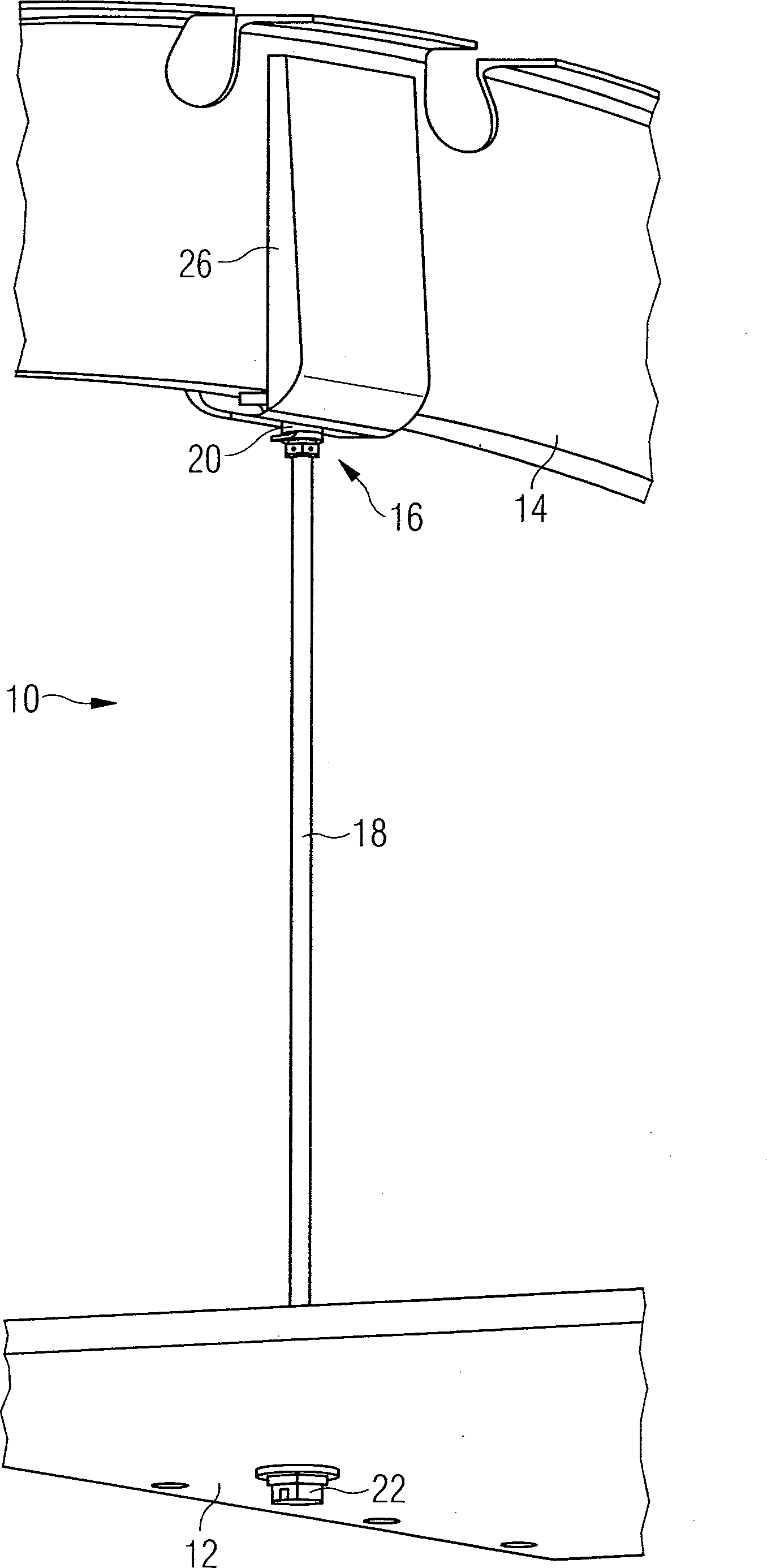
Die
Die in
Der Spant
Unter Bezugnahme insbesondere auf die
Durch das Zentrum des Gelenkkörpers
Zur Befestigung des einen Endes
Auf seiner vom Spant
Im durchmesserkleineren Teil der Durchgangsbohrung
Unter Bezugnahme auf die
Zur Verbindung der Einstellhülse
In zur Befestigungseinrichtung
Zum Aufschrauben der Einstellhülse
Der tragende Materialquerschnitt des Verbindungsrohrs
Claims (15)
Priority Applications (4)
| Application Number | Priority Date | Filing Date | Title |
|---|---|---|---|
| DE102010048243A DE102010048243A1 (en) | 2010-10-12 | 2010-10-12 | Holding device for interior trim parts of an airframe and fastening system with such holding devices |
| EP11767936.5A EP2627558A1 (en) | 2010-10-12 | 2011-10-11 | Holding device for interior lining parts of a fuselage and supporting system employing such holding devices |
| PCT/EP2011/005089 WO2012048855A1 (en) | 2010-10-12 | 2011-10-11 | Holding device for interior lining parts of a fuselage and supporting system employing such holding devices |
| US13/860,261 US9428258B2 (en) | 2010-10-12 | 2013-04-10 | Holding device for interior lining parts of a fuselage |
Applications Claiming Priority (1)
| Application Number | Priority Date | Filing Date | Title |
|---|---|---|---|
| DE102010048243A DE102010048243A1 (en) | 2010-10-12 | 2010-10-12 | Holding device for interior trim parts of an airframe and fastening system with such holding devices |
Publications (1)
| Publication Number | Publication Date |
|---|---|
| DE102010048243A1 true DE102010048243A1 (en) | 2012-04-12 |
Family
ID=44789419
Family Applications (1)
| Application Number | Title | Priority Date | Filing Date |
|---|---|---|---|
| DE102010048243A Ceased DE102010048243A1 (en) | 2010-10-12 | 2010-10-12 | Holding device for interior trim parts of an airframe and fastening system with such holding devices |
Country Status (4)
| Country | Link |
|---|---|
| US (1) | US9428258B2 (en) |
| EP (1) | EP2627558A1 (en) |
| DE (1) | DE102010048243A1 (en) |
| WO (1) | WO2012048855A1 (en) |
Cited By (1)
| Publication number | Priority date | Publication date | Assignee | Title |
|---|---|---|---|---|
| DE102015218074A1 (en) | 2015-09-21 | 2017-03-23 | Airbus Operations Gmbh | Connection system, connection arrangement and method |
Families Citing this family (4)
| Publication number | Priority date | Publication date | Assignee | Title |
|---|---|---|---|---|
| US10549823B2 (en) * | 2016-08-24 | 2020-02-04 | Mascorp, Ltd. | Damper mount |
| GB201701736D0 (en) * | 2017-02-02 | 2017-03-22 | Gripple Ltd | Securing assembly |
| EP4563463A1 (en) | 2023-11-30 | 2025-06-04 | Airbus Operations GmbH | Support element, fixation arrangement, and vehicle comprising same |
| EP4563462A1 (en) | 2023-11-30 | 2025-06-04 | Airbus Operations GmbH | Fixation glove, fixation arrangement, vehicle comprising same, and method for fixing a mounting structure to a support structure |
Family Cites Families (36)
| Publication number | Priority date | Publication date | Assignee | Title |
|---|---|---|---|---|
| US2126030A (en) * | 1935-07-13 | 1938-08-09 | Rca Corp | Antenna support |
| US2376279A (en) * | 1943-09-27 | 1945-05-15 | Schlenkert John Erwin | Ceiling hanger |
| US2762598A (en) * | 1953-02-16 | 1956-09-11 | Miller Co | Lighting fixture hangers |
| US2916309A (en) * | 1956-09-12 | 1959-12-08 | Wolar Isidore | Electric lighting fixtures |
| US3426489A (en) * | 1965-10-07 | 1969-02-11 | Paul Henri Lambert | False ceiling |
| US3512743A (en) * | 1966-11-14 | 1970-05-19 | Willis L Lipscomb | Adjustable lighting fixture hanger with wiring protection means |
| US3551012A (en) * | 1968-12-23 | 1970-12-29 | Wayne N Sutliff | Rod shock absorber |
| US3838661A (en) * | 1972-07-10 | 1974-10-01 | R Medley | Post |
| US3859770A (en) * | 1973-01-18 | 1975-01-14 | Trw Inc | Suspension system |
| US3842561A (en) * | 1973-06-14 | 1974-10-22 | M Wong | Adjustable ceiling strut |
| US4084364A (en) * | 1976-04-12 | 1978-04-18 | Roblin Industries, Inc. | Compression strut for suspended ceiling |
| US4114250A (en) * | 1976-08-16 | 1978-09-19 | Dent Robert K | Method of fixing a threaded tube to a threaded shank or nipple |
| US4686570A (en) | 1985-12-24 | 1987-08-11 | Rca Corporation | Analog-to-digital converter as for an adaptive television deghosting system |
| WO1987006993A1 (en) * | 1986-05-05 | 1987-11-19 | Moreno Albert M | Post support |
| US4720204A (en) * | 1986-10-23 | 1988-01-19 | Sterner Lighting Systems Incorporated | Banner arm break-away device |
| US4760495A (en) * | 1987-04-16 | 1988-07-26 | Prime Computer Inc. | Stand-off device |
| US5095673A (en) * | 1989-01-09 | 1992-03-17 | Spectrum Contracting, Inc. | System and method of installing roof insulation |
| US5080313A (en) * | 1989-04-24 | 1992-01-14 | Newport News Shipbuilding And Dry Dock Company | Pipe to plate connection |
| US4926607A (en) * | 1989-08-14 | 1990-05-22 | National Rolling Mills, Inc. | Compression leg |
| DE19610138C2 (en) * | 1996-03-15 | 2000-07-13 | Daimler Chrysler Aerospace | Reading lamp system for a passenger plane |
| US6382583B1 (en) * | 2000-04-18 | 2002-05-07 | Utd Incorporated | Releasable device and method |
| US6360507B1 (en) * | 2000-08-24 | 2002-03-26 | Icon International, Inc. | Universal support clip for suspended ceilings |
| US6557285B2 (en) * | 2000-12-28 | 2003-05-06 | Sears, Roebuck & Company | Hanging sign and support |
| US20020153033A1 (en) * | 2001-04-23 | 2002-10-24 | Miller Stephen F. | Collapsible structural frame strut with pop-in connector |
| US6709238B2 (en) * | 2002-07-03 | 2004-03-23 | John C. Marshall | Two-piece safety mechanism for ceiling fans |
| US8282673B2 (en) * | 2002-09-06 | 2012-10-09 | Jackson Roger P | Anti-splay medical implant closure with multi-surface removal aperture |
| GB2404716B (en) * | 2003-08-08 | 2007-07-25 | Ultra Electronics Ltd | A vibration isolation mount and method |
| US7455263B2 (en) * | 2005-04-22 | 2008-11-25 | The Boeing Company | Airplane interior systems |
| US7228669B1 (en) * | 2005-06-13 | 2007-06-12 | Yaraschefski Steven M | Suspended table assembly |
| DE102006058377B4 (en) * | 2006-12-08 | 2010-09-16 | Airbus Deutschland Gmbh | Rod for the structural reinforcement of a fuselage structure of an aircraft |
| US8281800B2 (en) * | 2007-07-03 | 2012-10-09 | Wcm Industries, Inc. | Faucet mounting sleeve |
| US8151821B2 (en) * | 2007-07-03 | 2012-04-10 | Wcm Industries, Inc. | Faucet mounting sleeve |
| DE102009010861B4 (en) | 2008-02-27 | 2016-04-14 | Airbus Operations Gmbh | Partition in an airplane |
| US8679275B2 (en) * | 2008-08-26 | 2014-03-25 | The Boeing Company | Composite tie rod and method for making the same |
| DE102009006578B4 (en) | 2009-01-29 | 2014-05-22 | Airbus Operations Gmbh | A vehicle having a cab with insulation packages and at least one fastener and method of attaching insulation packages |
| JP5633202B2 (en) * | 2010-06-11 | 2014-12-03 | 株式会社内山産業 | Ceiling fire extinguishing system |
-
2010
- 2010-10-12 DE DE102010048243A patent/DE102010048243A1/en not_active Ceased
-
2011
- 2011-10-11 EP EP11767936.5A patent/EP2627558A1/en not_active Withdrawn
- 2011-10-11 WO PCT/EP2011/005089 patent/WO2012048855A1/en not_active Ceased
-
2013
- 2013-04-10 US US13/860,261 patent/US9428258B2/en active Active
Cited By (3)
| Publication number | Priority date | Publication date | Assignee | Title |
|---|---|---|---|---|
| DE102015218074A1 (en) | 2015-09-21 | 2017-03-23 | Airbus Operations Gmbh | Connection system, connection arrangement and method |
| EP3147523A1 (en) | 2015-09-21 | 2017-03-29 | Airbus Operations GmbH | Connection system, connection arrangement and method |
| US10272529B2 (en) | 2015-09-21 | 2019-04-30 | Airbus Operations Gmbh | Connection system, connection arrangement and method |
Also Published As
| Publication number | Publication date |
|---|---|
| EP2627558A1 (en) | 2013-08-21 |
| US20130228667A1 (en) | 2013-09-05 |
| WO2012048855A1 (en) | 2012-04-19 |
| US9428258B2 (en) | 2016-08-30 |
Similar Documents
| Publication | Publication Date | Title |
|---|---|---|
| DE3734735C2 (en) | Captive fasteners for cladding | |
| EP2904278B1 (en) | Fastener bolt and fastener element having the same | |
| DE102010048243A1 (en) | Holding device for interior trim parts of an airframe and fastening system with such holding devices | |
| DE102013202791A1 (en) | Connecting arrangement between a wheel-guiding arm of a vehicle suspension and a flange | |
| DE102013224541A1 (en) | roller bearing | |
| DE102013106447B4 (en) | Connection node for a structure | |
| EP1679484A1 (en) | Device to attach ballistic protection elements. | |
| DE202009004831U1 (en) | Building anchor and building anchor system | |
| EP2088079A2 (en) | Fall protection device | |
| AT506224B1 (en) | STOPPING DEVICE FOR FALLING SAFETY | |
| DE102007032313A1 (en) | damping device | |
| DE202011100848U1 (en) | Scaffold anchoring device | |
| DE202005011463U1 (en) | Fall prevention device for roof workers, comprises threaded rod anchored in roof and secured inside support tube | |
| DE1294117B (en) | Safety device against unintentional loosening of a pipe connection | |
| DE102011100247A1 (en) | connection system | |
| DE202010012930U1 (en) | building anchors | |
| EP2865903A1 (en) | Expansion anchor with spring element | |
| DE3823000A1 (en) | Fastening element | |
| DE102007013509A1 (en) | fastening device | |
| DE102016211613A1 (en) | Heat shield arrangement of a combustion chamber with disc spring package | |
| AT526627B1 (en) | Clamping device for fall protection | |
| DE29820923U1 (en) | Fastener | |
| DE202005011008U1 (en) | Stabilizing device for launcher or similar system subjected to shock actions has telescoping tubes installed between ball joints on attachment points on damping system and each fixed by shear pin | |
| DE102008040576B4 (en) | Coupling element with a strand-shaped transmission element | |
| DE102018112783A1 (en) | System for bracing a built-in element in an interior of a vehicle |
Legal Events
| Date | Code | Title | Description |
|---|---|---|---|
| R002 | Refusal decision in examination/registration proceedings | ||
| R003 | Refusal decision now final |