DE102010029820A1 - Photovoltaic module i.e. thin layer photovoltaic module, for use in solar plant, has fastening device partially including wedge-working portion and/or clasping portion to enable wedge and/or clasp connection with retention device - Google Patents
Photovoltaic module i.e. thin layer photovoltaic module, for use in solar plant, has fastening device partially including wedge-working portion and/or clasping portion to enable wedge and/or clasp connection with retention device Download PDFInfo
- Publication number
- DE102010029820A1 DE102010029820A1 DE102010029820A DE102010029820A DE102010029820A1 DE 102010029820 A1 DE102010029820 A1 DE 102010029820A1 DE 102010029820 A DE102010029820 A DE 102010029820A DE 102010029820 A DE102010029820 A DE 102010029820A DE 102010029820 A1 DE102010029820 A1 DE 102010029820A1
- Authority
- DE
- Germany
- Prior art keywords
- wedge
- photovoltaic module
- holding device
- acting
- module
- Prior art date
- Legal status (The legal status is an assumption and is not a legal conclusion. Google has not performed a legal analysis and makes no representation as to the accuracy of the status listed.)
- Withdrawn
Links
- 230000014759 maintenance of location Effects 0.000 title abstract 3
- 238000000034 method Methods 0.000 claims abstract description 11
- 210000000689 upper leg Anatomy 0.000 claims description 31
- 125000006850 spacer group Chemical group 0.000 claims description 28
- 210000003414 extremity Anatomy 0.000 claims description 22
- 239000000463 material Substances 0.000 claims description 18
- 210000002414 leg Anatomy 0.000 claims description 14
- 239000010409 thin film Substances 0.000 claims description 4
- 239000004809 Teflon Substances 0.000 claims description 3
- 229920006362 Teflon® Polymers 0.000 claims description 3
- 238000009434 installation Methods 0.000 claims description 3
- 229920003229 poly(methyl methacrylate) Polymers 0.000 claims description 3
- 239000004926 polymethyl methacrylate Substances 0.000 claims description 3
- 238000006073 displacement reaction Methods 0.000 description 8
- 230000000694 effects Effects 0.000 description 7
- 238000013508 migration Methods 0.000 description 5
- 230000005012 migration Effects 0.000 description 5
- 238000003780 insertion Methods 0.000 description 4
- 230000037431 insertion Effects 0.000 description 4
- 229910000831 Steel Inorganic materials 0.000 description 3
- 230000009471 action Effects 0.000 description 3
- XAGFODPZIPBFFR-UHFFFAOYSA-N aluminium Chemical compound [Al] XAGFODPZIPBFFR-UHFFFAOYSA-N 0.000 description 3
- 229910052782 aluminium Inorganic materials 0.000 description 3
- 230000005484 gravity Effects 0.000 description 3
- 239000010959 steel Substances 0.000 description 3
- 229910000639 Spring steel Inorganic materials 0.000 description 2
- 230000008901 benefit Effects 0.000 description 2
- 238000010276 construction Methods 0.000 description 2
- 230000000630 rising effect Effects 0.000 description 2
- XLYOFNOQVPJJNP-UHFFFAOYSA-N water Substances O XLYOFNOQVPJJNP-UHFFFAOYSA-N 0.000 description 2
- 238000005452 bending Methods 0.000 description 1
- 230000015572 biosynthetic process Effects 0.000 description 1
- 230000001419 dependent effect Effects 0.000 description 1
- 238000013461 design Methods 0.000 description 1
- 238000011161 development Methods 0.000 description 1
- 239000002783 friction material Substances 0.000 description 1
- 230000007246 mechanism Effects 0.000 description 1
- 238000012986 modification Methods 0.000 description 1
- 230000004048 modification Effects 0.000 description 1
- 229910001220 stainless steel Inorganic materials 0.000 description 1
- 239000010935 stainless steel Substances 0.000 description 1
Images


Classifications
-
- F—MECHANICAL ENGINEERING; LIGHTING; HEATING; WEAPONS; BLASTING
- F24—HEATING; RANGES; VENTILATING
- F24S—SOLAR HEAT COLLECTORS; SOLAR HEAT SYSTEMS
- F24S25/00—Arrangement of stationary mountings or supports for solar heat collector modules
- F24S25/60—Fixation means, e.g. fasteners, specially adapted for supporting solar heat collector modules
- F24S25/63—Fixation means, e.g. fasteners, specially adapted for supporting solar heat collector modules for fixing modules or their peripheral frames to supporting elements
- F24S25/634—Clamps; Clips
-
- F—MECHANICAL ENGINEERING; LIGHTING; HEATING; WEAPONS; BLASTING
- F24—HEATING; RANGES; VENTILATING
- F24S—SOLAR HEAT COLLECTORS; SOLAR HEAT SYSTEMS
- F24S25/00—Arrangement of stationary mountings or supports for solar heat collector modules
- F24S25/60—Fixation means, e.g. fasteners, specially adapted for supporting solar heat collector modules
- F24S25/63—Fixation means, e.g. fasteners, specially adapted for supporting solar heat collector modules for fixing modules or their peripheral frames to supporting elements
- F24S25/632—Side connectors; Base connectors
-
- F—MECHANICAL ENGINEERING; LIGHTING; HEATING; WEAPONS; BLASTING
- F24—HEATING; RANGES; VENTILATING
- F24S—SOLAR HEAT COLLECTORS; SOLAR HEAT SYSTEMS
- F24S25/00—Arrangement of stationary mountings or supports for solar heat collector modules
- F24S25/60—Fixation means, e.g. fasteners, specially adapted for supporting solar heat collector modules
- F24S2025/6002—Fixation means, e.g. fasteners, specially adapted for supporting solar heat collector modules by using hooks
-
- Y—GENERAL TAGGING OF NEW TECHNOLOGICAL DEVELOPMENTS; GENERAL TAGGING OF CROSS-SECTIONAL TECHNOLOGIES SPANNING OVER SEVERAL SECTIONS OF THE IPC; TECHNICAL SUBJECTS COVERED BY FORMER USPC CROSS-REFERENCE ART COLLECTIONS [XRACs] AND DIGESTS
- Y02—TECHNOLOGIES OR APPLICATIONS FOR MITIGATION OR ADAPTATION AGAINST CLIMATE CHANGE
- Y02E—REDUCTION OF GREENHOUSE GAS [GHG] EMISSIONS, RELATED TO ENERGY GENERATION, TRANSMISSION OR DISTRIBUTION
- Y02E10/00—Energy generation through renewable energy sources
- Y02E10/40—Solar thermal energy, e.g. solar towers
- Y02E10/47—Mountings or tracking
Landscapes
- Engineering & Computer Science (AREA)
- Physics & Mathematics (AREA)
- Life Sciences & Earth Sciences (AREA)
- Sustainable Development (AREA)
- Sustainable Energy (AREA)
- Thermal Sciences (AREA)
- Chemical & Material Sciences (AREA)
- Combustion & Propulsion (AREA)
- Mechanical Engineering (AREA)
- General Engineering & Computer Science (AREA)
- Photovoltaic Devices (AREA)
Abstract
Description
Die Erfindung betrifft ein Photovoltaik-Modul, insbesondere ein Dünnschichtphotovoltaik-Modul, mit einer Vorrichtung zum Befestigen des Moduls an einer Haltevorrichtung.The invention relates to a photovoltaic module, in particular a thin-film photovoltaic module, with a device for fastening the module to a holding device.
Solche Photovoltaik-Module sind im Stand der Technik bekannt.
Um ein Verschieben des Photovoltaik-Moduls
Entlang einer Haltevorrichtung
Bei dieser bekannten Anordnung hat es sich jedoch als nachteilig herausgestellt, dass bei der Montage der Photovoltaik-Module
Es ist daher Aufgabe der vorliegenden Erfindung, ein Photovoltaik-Modul bereitzustellen, das einfacher montiert und demontiert werden kann. Es ist weiterhin Aufgabe der Erfindung ein vereinfachtes Modulmontageverfahren bereitzustellen.It is therefore an object of the present invention to provide a photovoltaic module, which can be easily assembled and disassembled. It is a further object of the invention to provide a simplified module mounting method.
Diese Aufgabe wird mit dem Photovoltaik-Modul nach Anspruch 1 gelöst. Dementsprechend weist die Vorrichtung zum Befestigen des Moduls zumindest teilweise mindestens einen keilwirkenden und/oder klammernden Abschnitt auf. Dank diesem keilwirkenden Abschnitt wird eine Keilverbindung mit der Haltevorrichtung ermöglicht. Dank dem keilwirkenden Abschnitt entstehen zwischen der Haltevorrichtung und der Vorrichtung zum Befestigen des Moduls im eingeschobenen Zustand Reibkräfte, die eine Bewegung des Moduls entlang der Haltevorrichtung
Bevorzugt kann der keilwirkende Abschnitt zur Extremität eines der Haltevorrichtung zugeordneten Endbereichs der Vorrichtung zum Befestigen hin sich verjüngend ausgebildet sein. Durch diese Abänderung der bekannten Vorrichtung zum Befestigen wird der gewünschte vorteilhafte Effekt erzielt. Bei einer schrägen Anordnung der Photovoltaik-Module beispielsweise auf einem Hausdach, wird dank der Schwerkraft das Photovoltaik-Modul in die Haltevorrichtung gedrückt.Preferably, the wedge-acting portion may be tapered towards the extremity of an end region of the device associated with the holding device for fastening. By this modification of the known device for fastening the desired advantageous effect is achieved. With an oblique arrangement of the photovoltaic modules, for example, on a house roof, the photovoltaic module is pressed into the holding device thanks to gravity.
Gemäß einer weiteren bevorzugten Ausführungsform kann der keilwirkende und/oder klammernde Abschnitt federnd ausgebildet sein. Hierdurch wird einerseits die Montage beim Einschieben der Vorrichtung zum Befestigen des Moduls in die Haltevorrichtung vereinfacht und andererseits im eingeschobenen Zustand die Kraftwirkung, die zwischen Modul und Haltevorrichtung auftritt, durch den Federmechanismus erhöht.According to a further preferred embodiment, the wedge-acting and / or clamping section may be resilient. As a result, on the one hand, the assembly is simplified when inserting the device for fastening the module in the holding device and on the other hand increases the force effect that occurs between the module and holding device in the retracted state by the spring mechanism.
Gemäß einer weiteren bevorzugten Ausführungsform kann der keilwirkende und/oder klammernde Abschnitt auf den Endbereich aufgesteckt werden. In dieser zweiteiligen Lösung kann die bekannte Anordnung an die erfindungsgemäße Ausführung angepasst werden.According to a further preferred embodiment, the wedge-acting and / or clamping section can be plugged onto the end region. In this two-part solution, the known arrangement can be adapted to the inventive design.
Weiter bevorzugt kann der keilwirkende und/oder klammernde Abschnitt über ein Federelement auf den Endbereich aufgesteckt werden. Dadurch können die beiden beschriebenen Vorteile kombiniert werden.More preferably, the wedge-acting and / or clinging section can be plugged onto the end region via a spring element. As a result, the two advantages described can be combined.
Gemäß einer bevorzugten Ausführungsform kann der keilwirkende Abschnitt an seinem breiten Ende eine Kante aufweisen. Insbesondere von Vorteil ist diese Ausführung dann, wenn im eingeschobenen Zustand das breite Ende des keilwirkenden Abschnitts an der Haltevorrichtung anliegt. Aufgrund der Keilform drückt dann die Kante am breiten Ende in die Haltevorrichtung, wodurch die Keilverbindung weiter verstärkt wird. According to a preferred embodiment, the wedge-acting portion may have an edge at its wide end. In particular, this embodiment is advantageous if in the inserted state, the wide end of the wedge-acting portion rests against the holding device. Due to the wedge shape then presses the edge at the wide end in the holder, whereby the wedge connection is further enhanced.
Vorteilhafterweise kann der keilwirkende Abschnitt an seinem verjüngten Ende abgerundet sein. Dies vereinfacht das Einführen der erfindungsgemäßen Vorrichtung zum Befestigen in die Haltevorrichtung.Advantageously, the wedge-acting portion may be rounded at its tapered end. This simplifies the insertion of the device according to the invention for fastening in the holding device.
Bevorzugt, kann der keilwirkende Abschnitt und der Endbereich im zusammengesetzten Zustand so ausgebildet sein, dass ihre Unterkanten schräg zueinander verlaufen, wobei die Unterkante des keilwirkenden Abschnitts im von der Extremität des Endbereichs entfernten Bereich über die Unterkante des Endbereichs übersteht. Hierdurch entsteht beim Einführen in eine Haltevorrichtung ein Hebel, der den keilwirkenden Abschnitt in die Haltevorrichtung drückt, wodurch die Keilwirkung weiter verstärkt wird. In dieser Ausführung ist die Kante am breiteren Ende des keilwirkenden Abschnitts an der Oberkante zum Modul hin angeordnet.Preferably, the wedge-acting portion and the end portion in the assembled state may be formed so that their lower edges are inclined to each other, wherein the lower edge of the wedge-acting portion projects beyond the lower edge of the end portion in the region remote from the extremity of the end portion. As a result, when inserted into a holding device, a lever is created which presses the wedge-acting section into the holding device, whereby the wedge effect is further enhanced. In this embodiment, the edge is located at the wider end of the wedge-acting portion at the top edge of the module.
Vorteilhafterweise kann der keilwirkende und/oder klammernde Abschnitt aus einem härteren Material als die Haltevorrichtung sein. Dadurch drückt sich die Vorrichtung zum Befestigen des Moduls mit dem keilwirkenden Abschnitt in die Haltevorrichtung, wodurch die Keilverbindung weiter optimiert wird. Z. B. kann die Haltevorrichtung aus Aluminium und der keilwirkende und/oder klammernde Abschnitt aus Stahl, insbesondere Edelstahl, sein.Advantageously, the wedge-acting and / or clamping portion may be made of a harder material than the holding device. As a result, the device for fastening the module with the wedge-acting portion presses into the holding device, whereby the wedge connection is further optimized. For example, the aluminum fixture and the wedge-acting and / or stapling section may be steel, particularly stainless steel.
Gemäß einer bevorzugten Ausführungsform kann mindestens eine der Haltevorrichtung zugewandten Oberflächen des keilwirkenden Abschnitts geriffelt sein. Durch die Riffelung wird die Keilverbindung weiter verstärkt.According to a preferred embodiment, at least one of the holding device facing surfaces of the wedge-acting portion may be corrugated. The corrugation further strengthens the wedge connection.
Bevorzugt kann der klammernde Abschnitt eine Grundplatte und mindestens ein von der Grundplatte weggebogenes Federplättchen aufweisen. Zwischen Federplättchen und Grundplatte kann die Haltevorrichtung eingespannt werden, um so das Verschieben der Haltevorrichtung zu verhindern. Dabei drückt im montierten Zustand das Federplättchen die Haltevorrichtung gegen die Grundplatte.Preferably, the stapling section may comprise a base plate and at least one spring plate bent away from the base plate. Between spring plate and base plate, the holding device can be clamped so as to prevent the displacement of the holding device. In this case, in the mounted state, the spring plate presses the holding device against the base plate.
Weiter kann das Federplättchen sich zu einer Extremität hin Richtung der von der Grundplatte beabstandeten Kante verjüngen, so dass sich zwischen der verjüngten Extremität der Federplättchen und der Grundplatte eine Ausnehmung ergibt. In die Ausnehmung kann die Haltevorrichtung geschoben werden.Furthermore, the spring plate can taper toward a limb in the direction of the edge spaced from the base plate, so that a recess results between the tapered limb of the spring plate and the base plate. In the recess, the holding device can be pushed.
Gemäß einer erfindungsgemäßen Weiterbildung kann das Federplättchen und die Grundplatte einen Schenkel der Haltevorrichtung im mit der mit einer Vorrichtung zum Befestigen des Moduls verbundenen Zustand umklammern. Hierdurch wird eine besonders gute Klammerverbindung erzielt.According to a development of the invention, the spring plate and the base plate can clasp a leg of the holding device in the state connected to a device for fixing the module. As a result, a particularly good clamp connection is achieved.
Bevorzugt, kann die dem Schenkel zugewandte Kante des Federplättchens als Schneidkante ausgebildet sein. Dadurch wird neben den Reibkräften auch noch eine formschlüssige Verbindung erzielt, die die Verschiebesicherheit weiter fördert. Denn die Schneidkante drückt sich in das Material der Haltevorrichtung.Preferably, the leg facing the edge of the spring plate may be formed as a cutting edge. As a result, in addition to the frictional forces also a positive connection is achieved, which further promotes the displacement safety. Because the cutting edge is expressed in the material of the holding device.
Besonders bevorzugt kann der klammernde Abschnitt zwei gegenläufig von der Grundplatte weggebogene Federplättchen aufweisen. Hierdurch kann die Halterung in beide Richtungen entlang der Haltevorrichtung gewährleistet werden.Particularly preferably, the clinging portion may have two oppositely bent away from the base plate spring plate. As a result, the holder can be ensured in both directions along the holding device.
Gemäß einer weiteren Ausführungsform, können die Federplättchen bzgl. der Grundplatte einen Winkel mit einem Betrag von <90°, insbesondere in einem Bereich von 30° bis 60°, bilden, wobei die Winkel der beiden Federplättchen unterschiedliche Vorzeichen aufweisen. Durch die Schrägstellung werden die Kräfte weiter optimiert und dies insbesondere im Zusammenhang mit der Variante mit Schneidkannte.According to a further embodiment, the spring plates with respect to the base plate can form an angle with an amount of <90 °, in particular in a range of 30 ° to 60 °, wherein the angle of the two spring plates have different signs. Due to the inclination, the forces are further optimized and this in particular in connection with the variant with Schneidkannte.
Gemäß einer bevorzugten Ausführungsform kann das Photovoltaik-Modul mindestens zwei Vorrichtungen zum Befestigen aufweisen, wobei an lediglich einer Vorrichtung zum Befestigen zumindest ein keilwirkender und/der klammernder Abschnitt angeordnet sein kann. Dank der Keilverbindung und/oder der klammernden Verbindung wird ein laterales Verschieben des Photovoltaik-Moduls unterdrückt. Dadurch, dass die anderen Endbereiche den keilwirkenden und/oder klammernden Abschnitt nicht aufweisen, können eventuell auftretende Spannungen, die sich bei starkem Wind bzw. starken Temperaturschwankungen ergeben könnten, nicht ins Modul selbst übertragen, wodurch eine Beeinträchtigung der Lebensdauer des Moduls, beispielsweise durch Beschädigungen, insbesondere Risse, verhindert oder zumindest abgeschwächt werden kann.According to a preferred embodiment, the photovoltaic module can have at least two fastening devices, wherein at least one fastening device can be arranged on at least one wedge-acting and / or clamping section. Thanks to the spline connection and / or the clamping connection, a lateral displacement of the photovoltaic module is suppressed. Due to the fact that the other end regions do not have the wedge-acting and / or clinging section, any occurring stresses which could result in strong wind or strong temperature fluctuations can not be transferred into the module itself, which would impair the life of the module, for example due to damage , in particular cracks, can be prevented or at least mitigated.
Vorteilhafterweise kann die Vorrichtung zum Befestigen so ausgebildet sein, dass das Photovoltaik-Modul an zwei Haltevorrichtungen befestigbar ist, wobei der keilwirkende und/oder klammernde Abschnitt nur einer der beiden Haltevorrichtungen zugeordnet ist. Dadurch wird das Auftreten von unerwünschten Spannungen im Modul, die sich aus Temperaturschwankungen oder starken Winden ergeben können, unterdrückt bzw. reduziert. In dieser Ausführung befindet sich der keilwirkende und/oder klammernde Abschnitt somit nur an einem Endbereich der Vorrichtung zum Befestigen.Advantageously, the device for fastening can be designed so that the photovoltaic module can be fastened to two holding devices, wherein the wedge-acting and / or clamping section is assigned to only one of the two holding devices. This will cause the occurrence of unwanted stresses in the module resulting from temperature fluctuations or strong winds can, suppress or reduce. In this embodiment, the wedge-acting and / or clamping section is thus located only at one end region of the fastening device.
Die Erfindung betrifft auch keilwirkende Abschnitte die auf Vorrichtungen zum Befestigen von Photovoltaik-Modulen aufgesetzt werden können.The invention also relates to wedge-acting sections which can be placed on devices for fixing photovoltaic modules.
Bevorzugt kann der keilwirkende Abschnitt der Vorrichtung zum Befestigen mindestens eine offene Klemmrolle mit nach außen aufgebogenen Endbereichen umfasst. Die nach außen aufgebogenen Endbereiche bewirken im eingeschobenen Zustand eine ausreichend hohe Kraft um ein Wandern des Moduls im eingeschobenen Zustand zu verhindern.Preferably, the wedge-acting portion of the fastening device comprises at least one open pinch roller with outwardly bent end portions. The outwardly bent end portions cause in the inserted state a sufficiently high force to prevent migration of the module in the inserted state.
Bevorzugt kann der keilwirkende Abschnitt an seiner Extremität einen Dorn oder eine sägezahnförmige Struktur aufweisen um eine Wandern des Moduls zu verhindern.Preferably, the wedge-acting portion may have at its extremity a mandrel or a sawtooth-shaped structure to prevent migration of the module.
Die Aufgabe der Erfindung wird auch mit einer Solaranlage nach Anspruch 22 gelöst. Diese umfasst ein in eine Haltevorrichtung eingeschobenes Photovoltaik-Modul und mindestens ein auf die Haltevorrichtung aufgeschobenes oder aufgeklipstes Klammerelement, um ein Wandern des Photovoltaik-Moduls entlang der Haltevorrichtung zu verhindern. Dank dem Klammerelement, das ohne jegliches Werkzeug angebracht werden kann wird das Wandern verhindert und gleichzeitig die Montage vereinfacht.The object of the invention is also achieved with a solar system according to claim 22. This comprises a photovoltaic module inserted into a holding device and at least one clip element pushed or clipped onto the holding device in order to prevent the photovoltaic module from wandering along the holding device. Thanks to the clip element, which can be attached without any tools, it prevents walking and at the same time simplifies assembly.
Bevorzugt können zwei Klammerelemente links und rechts neben einem Endbereich einer Vorrichtung zum Befestigen des Moduls an der Haltevorrichtung angeordnet sein. Somit wird ein Wandern in beide Richtungen verhindert.Preferably, two clip elements can be arranged to the left and to the right of an end region of a device for fastening the module to the holding device. This prevents walking in both directions.
Weiter bevorzugt können die beiden Klammerelemente über eine Steg miteinander verbunden sind. Somit ist nur ein Klammerelement nötig, um ein Verschieben entlang der Haltevorrichtung in beide Richtungen zu unterdrücken.More preferably, the two clip elements can be connected to one another via a web. Thus, only one clip member is needed to suppress displacement along the fixture in both directions.
Gemäß einer vorteilhaften Variante, kann das Klammerelement ein Griffelement aufweisen. Hierdurch wird ermöglicht, dass man schon zwischen installierte Module eine Verschiebsicherung aufklipsen kann, ohne die Module abbauen zu müssen. Mit dem Griffelement kann man das Klammerelement leicht zwischen zwei Module einführen und an der Haltevorrichtung anbringen.According to an advantageous variant, the clamping element may comprise a grip element. This makes it possible to clip on a slip protection between installed modules, without having to dismantle the modules. With the handle element you can easily insert the clamp element between two modules and attach to the fixture.
Bevorzugt kann das Griffelement im montierten Zustand auf der Oberseite des Stegelements (
Gemäß eines weiteren Aspekts, kann das Klammerelement auf seiner Haltevorrichtung zugewandten Seite einen oder mehrere Dorne aufweisen, wobei das Material des Klammerelements härter ist als das Material der Haltevorrichtung. Dadurch kann neben einem Reibschluss auch ein Formschluss erzielt werden, wodurch das Wandern eines Moduls entlang der Haltevorrichtung unterbundne werden kann.According to a further aspect, the clamping element may have on its holding device facing side one or more mandrels, wherein the material of the clamping element is harder than the material of the holding device. As a result, in addition to a frictional connection, a positive connection can also be achieved, as a result of which the migration of a module along the holding device can be interrupted.
Alternativ oder zusätzlich kann erfindungsgemäß mindestens eine im montierten Zustand der Haltevorrichtung zugewandte Kante scharfkantig ausgebildet sein, wobei das Material des Klammerelements härter als das Material der Haltevorrichtung ist. Diese Kante kann sich in die Haltevorrichtung eindrücken und ermöglicht so einen Formschluss.Alternatively or additionally, according to the invention, at least one edge facing in the mounted state of the holding device can be made sharp-edged, the material of the clamping element being harder than the material of the holding device. This edge can be pressed into the holding device and thus enables a positive connection.
Die Erfindung betrifft auch die Verwendung eines Klammerelements in einer solchen Solaranlage und bevorzugt die Verwendung eines Klammerelements mit Griffelement.The invention also relates to the use of a clamping element in such a solar system and preferably the use of a clamping element with handle element.
Die Erfindung betrifft weiterhin eine Solaranlage mit mindestens zwei nebeneinander angeordneten Photovoltaik-Modulen nach Anspruch 25. Bei diesen Modulen kann es sich insbesondere um ein Modul, wie oben beschrieben, handeln. Es können jedoch auch herkömmliche Module zum Einsatz kommen. Die zwei nebeneinander angeordneten Photovoltaik-Module sind dabei mit mindestens einer Haltevorrichtung verbunden. Die Erfindung ist dadurch gekennzeichnet, dass zwischen dem Photovoltaik-Modul ein auf zumindest ein Photovoltaik-Modul aufschiebbares Abstandselement angeordnet ist. Das aufschiebbare Abstandselement ersetzt dabei das aus dem Stand der Technik bekannte, auf die Rückseite oder Vorderseite eines Moduls aufgeklebte Abstandselement und verbessert somit die Positionierung der zwei Module. Insbesondere bei Photovoltaik-Modulen, die nicht den oben beschriebenen, keilwirkenden Abschnitt aufweisen, verhindern diese Abstandselemente ein ungewolltes Berühren der Kanten zweier Module und Schäden im Randbereich der Module können verhindert werden.The invention further relates to a solar system with at least two juxtaposed photovoltaic modules according to
Bevorzugt kann das Abstandselement ein vorgespanntes, im Wesentlichen U-förmiges Greifelement umfassen. Dank dem U-förmigen Greifelement, das auf das Photovoltaik-Modul aufgeschoben werden kann, wird ein sicheres Anbringen des Abstandselements an einem Modul ermöglicht. Durch die Vorspannung der Schenkel des U-förmigen Elements, wird ein ungewolltes Herausrutschen des Abstandselements, selbst wenn die zwei Photovoltaik-Module nicht aneinander anliegen, verhindert.Preferably, the spacer element may comprise a prestressed, substantially U-shaped gripping element. Thanks to the U-shaped gripping element, which can be pushed onto the photovoltaic module, a secure attachment of the spacer is made possible on a module. By biasing the legs of the U-shaped element, an unwanted slipping out of the spacer, even if the two photovoltaic modules do not abut each other prevented.
Ferner bevorzugt kann das U-förmige Greifelement auf der Innenseite stegförmige Bereiche aufweisen. Diese ermöglichen ein Abfließen von Wasser und erleichtern aufgrund der reduzierten Berührungsfläche ein Aufschieben des Abstandshalters, insbesondere bei schon installierten Solaranlagen.Further preferably, the U-shaped gripping element on the inside have web-shaped areas. These allow a drainage of water and facilitate the sliding of the spacer due to the reduced contact surface, especially in already installed solar systems.
Gemäß einer bevorzugten Ausführungsform können die Innenseite und/oder die stegförmigen Bereiche aus einem weicheren Material als die Außenseite sein. Dadurch wird die gewünschte Stabilität beim gleichzeitigen Verhindern von Beschädigungen an den Solarmodulen erzielt.According to a preferred embodiment, the inside and / or the web-shaped regions may be made of a softer material than the outside. This achieves the desired stability while simultaneously preventing damage to the solar modules.
Vorteilhafterweise kann das Abstandselement eine, insbesondere aufsteckbare, Kabelführung aufweisen. Dadurch kann die für die elektrische Verbindung der Solarmodule benötigte Kabelverbindung sicher verlegt werden.Advantageously, the spacing element can have a, in particular attachable, cable guide. As a result, the cable connection required for the electrical connection of the solar modules can be securely laid.
Die Erfindung betrifft auch ein Verfahren zum Montieren von Photovoltaik-Modulen mit mindestens einer Vorrichtung zum Befestigen des Moduls an einer Haltevorrichtung mit einem Aufnahmeprofil mit den Schritten:
- a. Verschieben eines Moduls auf der Oberfläche eines Schenkels des Aufnahmeprofils außerhalb des Aufnahmeprofils bis an eine Endposition
- b. Bereitstellen eines keilwirkenden und/oder klammernden Abschnitts (
350 ) an einem Endbereich der Vorrichtung zum Befestigen, und - c. Einschieben des Endbereichs mit keilwirkendem und/oder klammernden Abschnitt an der Endposition in das Aufnahmeprofil.
- a. Moving a module on the surface of a leg of the receiving profile outside the receiving profile to an end position
- b. Providing a wedge-acting and / or stapling section (
350 ) at an end portion of the fastening device, and - c. Insertion of the end region with wedge-acting and / or clinging section at the end position into the receiving profile.
Mit diesem Verfahren kann ein Modul ohne größere Kraftanstrenungen an seine Endposition gebracht werden, und danach an der Endposition gegen Verschieben entlang der Haltevorrichtung gesichert werden. Dabei kommen die oben beschriebenen erfindungsgemäßen Abschnitte zum Einsatz.With this method, a module can be brought to its final position without major effort, and then secured at the end position against displacement along the holding device. In this case, the above-described inventive sections are used.
Bevorzugt kann vor Schritt a) eine Montageschiene in einen Schlitz auf der Oberfläche des Schenkels eingesetzt werden. An dieser Schiene kann dann im Schritt a) das Modul verschoben werden. Vorteilhafterweise steht die Montageschiene über die Oberfläche über. Dadurch wird das Verfahren vereinfacht, da das Modul nicht abrutschen kann.Preferably, prior to step a) a mounting rail can be inserted into a slot on the surface of the leg. On this rail, the module can then be moved in step a). Advantageously, the mounting rail over the surface over. This simplifies the procedure because the module can not slip off.
Weiter bevorzugt kann die Montageschiene aus einem Material mit niedrigem Reibungskoeffizienten hergestellt ist, insbesondere aus Teflon oder Acryl-Glas. Dies vereinfacht die Bewegung entlang der der Schiene.More preferably, the mounting rail is made of a material having a low coefficient of friction, in particular Teflon or acrylic glass. This simplifies the movement along the rail.
Weitere bevorzugte Ausführungsformen ergeben sich aus den abhängigen Ansprüchen.Further preferred embodiments will be apparent from the dependent claims.
Die Erfindung wird nachfolgend anhand der in den Figuren dargestellten erfindungsgemäßen Ausführungsformen beschrieben. Es zeigen:The invention will be described below with reference to the embodiments according to the invention shown in the figures. Show it:
Im in der
Entsprechend der Erfindung weist der untere Endabschnitt
Bei der Demontage kann diese kraftschlüssige Verbindung durch einfaches Hochschieben des Photovoltaik-Moduls
Um die verkeilende Wirkung des sich zur Extremität
In diesen Ausführungsformen ist nur der Endbereich
Durch den Einsatz des keilwirkenden Abschnitts
Gemäß einer Variante kann der keilwirkende Abschnitt
Die
Im Endbereich
Der keilwirkende Abschnitt umfasst zwei Füße
Weiter umfasst der keilwirkende Abschnitt
Die Seitenwände
Der dargestellte keilwirkende Abschnitt ist in dieser Ausführungsform aus Stahl und kann aus einem Blech gestanzt oder gelasert werden.The illustrated wedge-acting portion in this embodiment is made of steel and can be punched or laser-cut from a sheet.
Beim Einschieben des Endabschnitts
Damit der Endbereich
Aufgrund der Federwirkung wird, wie durch den Pfeil angedeutet, im Endzustand der keilwirkende Abschnitt
Üblicherweise werden, beispielsweise aus Gewichtsgründen, die Haltevorrichtungen aus Aluminium hergestellt, während der keilwirkende Abschnitt
Dank der Spitze bzw. Kante
Das erfindungsgemäße Photovoltaik-Modul sitzt somit sicher in der Haltevorrichtung
Im zusammengesetzten Zustand und ohne äußere Krafteinwirkungen verläuft die Unterkante
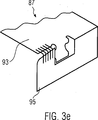
Die
Diese Ausführungsformen lassen sich mit der vierten und/oder fünften Ausführungsform kombinieren. Gemäß einer weiteren Variante können die dorn- oder sägezahnförmigen Fortsätze auch direkt am Endbereich
Wie in
Gemäß einer Variante kann ein Klammerelement
Das Griffelement
Im Gegensatz zum hakenförmigen Ende
Um neben der reibschlüssigen Verbindung auch noch eine fromschlüssige Verbindung zu erzielen, können auf der im montierten Zustand der Haltevorrichtung
Der Durchmesser der Klemmrolle
An der Grundplatte
In der dargestellten Ausführungsform bilden die Federplättchen
Dieser Zustand wird anhand einer Querschnittsansicht in
Um diese klammernde Wirkung noch weiter zu verbessern, ist die Unterkante
Durch die Keilverbindung am Endabschnitt
Kommt eine Klammerelement
Die einzelnen Merkmale der verschiedenen Ausführungsformen 1 bis 11 können beliebig miteinander kombiniert werden, um weitere erfindungsgemäße Varianten zu erzielen.The individual features of the
Um zusätzlich oder unabhängig von der Keilverbindung zwischen Vorrichtungen zum Befestigen des Moduls mit der Haltevorrichtung den Abstand zwischen zwei Modulen sichern zu können, wird entsprechend einer zwölften Ausführungsform der Erfindung ein Abstandselement zwischen zwei Modulen angeordnet.In order to be able to secure the distance between two modules in addition to or independently of the spline connection between devices for fastening the module to the holding device, according to a twelfth embodiment of the invention, a spacing element is arranged between two modules.
Um eine Beschädigung des Moduls
Um die Positionierung des Abstandhalters
Dank der aufschiebbar ausgeführten Abstandselemente können auch schon installierte Solaranlagen mit mehreren Photovoltaik-Modulen durch einfaches Aufschieben der Abstandshalter nachgerüstet werden.Thanks to the retractable spacers already installed solar systems with multiple photovoltaic modules can be retrofitted by simply sliding the spacers.
Die Merkmale der verschiedenen Ausführungsformen des Abstandselements, die in den
Nachfolgend wird ein Montageverfahren entsprechend einer fünfzehnten Ausführungsform der Erfindung beschrieben.Hereinafter, an assembling method according to a fifteenth embodiment of the invention will be described.
Die
Daneben zeigt
Das Modul
Dieser Zustand wird in
Der Endbereich
In
Um das Gleiten zu vereinfachen ist die Montageschiene bevorzugt aus einem Material mit niedrigem Reibungskoeffizienten hergestellt, beispielsweise aus Teflon oder Acryl-Glas.To facilitate sliding, the mounting rail is preferably made of a low coefficient of friction material, such as Teflon or acrylic glass.
Im nächsten Schritt wird das Modul
Danach wird das Modul
Schließlich wird die Montageschiene
Sollte ein schon montiertes Modul ausgetauscht werden, wird es in Richtung des Pfeils
Mit dem erfindungsgemäßen Verfahren lassen sich Module leicht an ihre Endposition bringen und nach Einsetzen des Endabschnitts und Einschieben ins Profil
Claims (38)
Priority Applications (1)
| Application Number | Priority Date | Filing Date | Title |
|---|---|---|---|
| DE102010029820A DE102010029820A1 (en) | 2009-12-30 | 2010-06-08 | Photovoltaic module i.e. thin layer photovoltaic module, for use in solar plant, has fastening device partially including wedge-working portion and/or clasping portion to enable wedge and/or clasp connection with retention device |
Applications Claiming Priority (3)
| Application Number | Priority Date | Filing Date | Title |
|---|---|---|---|
| DE102009060752 | 2009-12-30 | ||
| DE102009060752.8 | 2009-12-30 | ||
| DE102010029820A DE102010029820A1 (en) | 2009-12-30 | 2010-06-08 | Photovoltaic module i.e. thin layer photovoltaic module, for use in solar plant, has fastening device partially including wedge-working portion and/or clasping portion to enable wedge and/or clasp connection with retention device |
Publications (1)
| Publication Number | Publication Date |
|---|---|
| DE102010029820A1 true DE102010029820A1 (en) | 2011-07-07 |
Family
ID=44312593
Family Applications (1)
| Application Number | Title | Priority Date | Filing Date |
|---|---|---|---|
| DE102010029820A Withdrawn DE102010029820A1 (en) | 2009-12-30 | 2010-06-08 | Photovoltaic module i.e. thin layer photovoltaic module, for use in solar plant, has fastening device partially including wedge-working portion and/or clasping portion to enable wedge and/or clasp connection with retention device |
Country Status (1)
| Country | Link |
|---|---|
| DE (1) | DE102010029820A1 (en) |
Cited By (5)
| Publication number | Priority date | Publication date | Assignee | Title |
|---|---|---|---|---|
| DE102011053774A1 (en) * | 2011-09-20 | 2013-03-21 | Rehau Ag + Co | Clamping element for a fastening system for plate-shaped elements, fastening system comprising such a clamping element, and its use |
| EP2618072A1 (en) * | 2012-01-19 | 2013-07-24 | Roto Frank AG | Solar module assembly and method for producing a solar module assembly |
| FR3001479A1 (en) * | 2013-01-31 | 2014-08-01 | Idesun | Device for fastening of solar panel on roof formed by ribbed or undulated roofing units of e.g. industrial building, has housing with edges allowed to respectively belong to two adjacent panels according to direction of slope of roof |
| EP3550158A1 (en) * | 2018-04-04 | 2019-10-09 | A. Raymond et Cie | Clip for attaching photovoltaic frame for mounting by insertion and then sliding in a slot of a supporting wall |
| US12003207B1 (en) | 2022-06-12 | 2024-06-04 | Sunmodo Corporation | Device and system for mounting solar panels to roofs and the like |
Citations (7)
| Publication number | Priority date | Publication date | Assignee | Title |
|---|---|---|---|---|
| DE20108075U1 (en) * | 2001-05-12 | 2001-07-19 | Stiebel Eltron GmbH & Co. KG, 37603 Holzminden | Solar panel |
| DE102005061709A1 (en) * | 2004-12-21 | 2007-03-15 | Heisterkamp, Norbert, Dr.-Ing. | Solar roof structure for solar energy has a sheet with trapezoidal corrugations, flutes and valleys as well as support padding to relieve pressure and absorb vibration |
| DE202008011312U1 (en) * | 2008-08-25 | 2008-12-04 | Ideematec Deutschland Gmbh | Locking system for locking flat solar modules |
| DE202008015916U1 (en) * | 2008-12-02 | 2009-02-19 | Solarmarkt Ag | Profile arrangement for fixing at least one solar module to a support structure and device with a connected via a profile arrangement with a support structure solar module |
| DE102008006106A1 (en) * | 2008-01-25 | 2009-07-30 | Solarmarkt Ag | Solar module mounting system |
| DE102008000293A1 (en) * | 2008-02-13 | 2009-08-20 | Hilti Aktiengesellschaft | Fastening device for the attachment of plate-shaped elements |
| DE202008009241U1 (en) * | 2008-07-10 | 2009-11-26 | Rehau Ag + Co | Retaining profile and sealing profile for plate-shaped modules |
-
2010
- 2010-06-08 DE DE102010029820A patent/DE102010029820A1/en not_active Withdrawn
Patent Citations (7)
| Publication number | Priority date | Publication date | Assignee | Title |
|---|---|---|---|---|
| DE20108075U1 (en) * | 2001-05-12 | 2001-07-19 | Stiebel Eltron GmbH & Co. KG, 37603 Holzminden | Solar panel |
| DE102005061709A1 (en) * | 2004-12-21 | 2007-03-15 | Heisterkamp, Norbert, Dr.-Ing. | Solar roof structure for solar energy has a sheet with trapezoidal corrugations, flutes and valleys as well as support padding to relieve pressure and absorb vibration |
| DE102008006106A1 (en) * | 2008-01-25 | 2009-07-30 | Solarmarkt Ag | Solar module mounting system |
| DE102008000293A1 (en) * | 2008-02-13 | 2009-08-20 | Hilti Aktiengesellschaft | Fastening device for the attachment of plate-shaped elements |
| DE202008009241U1 (en) * | 2008-07-10 | 2009-11-26 | Rehau Ag + Co | Retaining profile and sealing profile for plate-shaped modules |
| DE202008011312U1 (en) * | 2008-08-25 | 2008-12-04 | Ideematec Deutschland Gmbh | Locking system for locking flat solar modules |
| DE202008015916U1 (en) * | 2008-12-02 | 2009-02-19 | Solarmarkt Ag | Profile arrangement for fixing at least one solar module to a support structure and device with a connected via a profile arrangement with a support structure solar module |
Cited By (10)
| Publication number | Priority date | Publication date | Assignee | Title |
|---|---|---|---|---|
| DE102011053774A1 (en) * | 2011-09-20 | 2013-03-21 | Rehau Ag + Co | Clamping element for a fastening system for plate-shaped elements, fastening system comprising such a clamping element, and its use |
| EP2573486A3 (en) * | 2011-09-20 | 2013-06-26 | REHAU AG + Co | Clamp element for a fixing system for panel-shaped elements, fixing system comprising such a clamp element and use of same |
| EP2618072A1 (en) * | 2012-01-19 | 2013-07-24 | Roto Frank AG | Solar module assembly and method for producing a solar module assembly |
| FR3001479A1 (en) * | 2013-01-31 | 2014-08-01 | Idesun | Device for fastening of solar panel on roof formed by ribbed or undulated roofing units of e.g. industrial building, has housing with edges allowed to respectively belong to two adjacent panels according to direction of slope of roof |
| EP3550158A1 (en) * | 2018-04-04 | 2019-10-09 | A. Raymond et Cie | Clip for attaching photovoltaic frame for mounting by insertion and then sliding in a slot of a supporting wall |
| FR3079890A1 (en) * | 2018-04-04 | 2019-10-11 | A. Raymond Et Cie | FASTENING CLIP FOR PHOTOVOLTAIC CHASSIS WITH INSERTION MOUNTING THEN SLIDING IN A SLOT OF A SUPPORT WALL. |
| US10530293B2 (en) | 2018-04-04 | 2020-01-07 | A. Raymond Et Cie | Fastening staple for a photovoltaic framework with mounting by insertion and then sliding into a slot of a support wall |
| USRE49902E1 (en) | 2018-04-04 | 2024-04-02 | A. Raymond Et Cie | Fastening staple for a photovoltaic framework with mounting by insertion and then sliding into a slot of a support wall |
| US12003207B1 (en) | 2022-06-12 | 2024-06-04 | Sunmodo Corporation | Device and system for mounting solar panels to roofs and the like |
| US12003205B2 (en) | 2022-06-12 | 2024-06-04 | Sunmodo Corporation | Device and system for mounting solar panels to roofs and the like |
Similar Documents
| Publication | Publication Date | Title |
|---|---|---|
| DE102010022556B3 (en) | Device i.e. fastening clamp, for fastening solar module at carrier rail, has front and base walls and flanges arranged for rear engagement of edge regions of engagement recess with rear engaging edges that face solar module | |
| DE102011012438B4 (en) | Construction kit for fastening device | |
| DE102008009608A1 (en) | Planar element and clamping device combination, has planar element including profile rib for clamping device, where profile rib is formed with constrictions that oppose one another, and constrictions form undercuts for clamping device | |
| EP2309552A1 (en) | Clamping holder and fixing device for fixing plate like construction elements and method for producing the fixing device | |
| EP2270403A1 (en) | Bearing rail | |
| DE102009043993A1 (en) | Distance element to the floorboards of a floor bearing attachment to a support beam | |
| DE3445935C3 (en) | One-piece clamp-shaped holder for elongated objects | |
| DE102010029820A1 (en) | Photovoltaic module i.e. thin layer photovoltaic module, for use in solar plant, has fastening device partially including wedge-working portion and/or clasping portion to enable wedge and/or clasp connection with retention device | |
| EP2631414B1 (en) | Guide rail for vertical awning and vertical awning | |
| DE102008009633B4 (en) | Surface element with at least one profile rib | |
| DE202008011188U1 (en) | Identification device for an electrical line | |
| DE202009016197U1 (en) | For fixing an object serving holding element and fastening device for solar modules | |
| EP2183736B1 (en) | Identification device for electrical lines | |
| EP0404726A2 (en) | Device for connecting c-shaped rails, especially mounting rails | |
| DE102013011245B4 (en) | Fixing system for string-shaped elements, in particular cables in wind turbines | |
| DE29712614U1 (en) | Cuff rail fitting | |
| DE29618192U1 (en) | Cavity anchor | |
| DE2924674A1 (en) | FASTENING DEVICE FOR WALL COVERING ELEMENTS | |
| EP3754845B1 (en) | Apparatus for absorbing electrical noise | |
| DE202007008150U1 (en) | Fixing device for solar modules | |
| DE202011108404U1 (en) | mounting assembly | |
| DE102018005072B4 (en) | Fastening element for mounting a facade panel | |
| DE202021104587U1 (en) | Connector bracket for connecting a cover member and a trim member to a window frame and roof window comprising such a connector bracket | |
| DE2804419A1 (en) | cable runway also supporting electrical fittings - has locking grooves along upper edges of side walls to hold cable bridges in position | |
| AT500069B1 (en) | CABLE BRACKET |
Legal Events
| Date | Code | Title | Description |
|---|---|---|---|
| R119 | Application deemed withdrawn, or ip right lapsed, due to non-payment of renewal fee |
Effective date: 20140101 |