[go: up one dir, main page]

DE102010020910B4 - Method and apparatus for determining a frequency mask for a frequency spectrum - Google Patents

Method and apparatus for determining a frequency mask for a frequency spectrum Download PDF

Info

Publication number
DE102010020910B4
DE102010020910B4 DE102010020910.4A DE102010020910A DE102010020910B4 DE 102010020910 B4 DE102010020910 B4 DE 102010020910B4 DE 102010020910 A DE102010020910 A DE 102010020910A DE 102010020910 B4 DE102010020910 B4 DE 102010020910B4
Authority
DE
Germany
Prior art keywords
frequency
ordinate
ordinate values
frequency spectrum
values
Prior art date
Legal status (The legal status is an assumption and is not a legal conclusion. Google has not performed a legal analysis and makes no representation as to the accuracy of the status listed.)
Expired - Fee Related
Application number
DE102010020910.4A
Other languages
German (de)
Other versions
DE102010020910A1 (en
Inventor
Hagen Eckert
Jochen Pliquett
Current Assignee (The listed assignees may be inaccurate. Google has not performed a legal analysis and makes no representation or warranty as to the accuracy of the list.)
Rohde and Schwarz GmbH and Co KG
Original Assignee
Rohde and Schwarz GmbH and Co KG
Priority date (The priority date is an assumption and is not a legal conclusion. Google has not performed a legal analysis and makes no representation as to the accuracy of the date listed.)
Filing date
Publication date
Application filed by Rohde and Schwarz GmbH and Co KG filed Critical Rohde and Schwarz GmbH and Co KG
Priority to DE102010020910.4A priority Critical patent/DE102010020910B4/en
Priority to US12/967,881 priority patent/US8442789B2/en
Publication of DE102010020910A1 publication Critical patent/DE102010020910A1/en
Application granted granted Critical
Publication of DE102010020910B4 publication Critical patent/DE102010020910B4/en
Expired - Fee Related legal-status Critical Current
Anticipated expiration legal-status Critical

Links

Images

Classifications

    • GPHYSICS
    • G01MEASURING; TESTING
    • G01RMEASURING ELECTRIC VARIABLES; MEASURING MAGNETIC VARIABLES
    • G01R23/00Arrangements for measuring frequencies; Arrangements for analysing frequency spectra
    • G01R23/16Spectrum analysis; Fourier analysis
    • G01R23/18Spectrum analysis; Fourier analysis with provision for recording frequency spectrum

Landscapes

  • Physics & Mathematics (AREA)
  • Mathematical Physics (AREA)
  • General Physics & Mathematics (AREA)
  • Measurement Of Mechanical Vibrations Or Ultrasonic Waves (AREA)

Abstract

Verfahren zur Ermittlung einer oberhalb oder unterhalb eines Frequenzspektrums eines erfassten Signals befindlichen Frequenzmaske mit folgenden auf einer Recheneinrichtung automatisch ablaufenden Verfahrensschritten:• Ermitteln jedes einzelnen Ordinatenwertes einer vollständig oberhalb bzw. unterhalb des Frequenzspektrums befindlichen ersten Hüllkurve als Maximalwert bzw. Minimalwert einer bestimmten Anzahl von jeweils benachbarten und mit einer Fensterfunktion (w(n), w(n)) verknüpften Ordinatenwerten (S(n), S(n)) des Frequenzspektrums,• Ermitteln jedes einzelnen Ordinatenwertes einer vollständig oberhalb bzw. unterhalb des Frequenzspektrums und vollständig oberhalb bzw. unterhalb der ersten Hüllkurve befindlichen zweiten Hüllkurve als Maximalwert bzw. Minimalwert einer bestimmten Anzahl von jeweils benachbarten und mit einer Fensterfunktion (w(n), (n)) verknüpften Ordinatenwerten (S(n), S(n)) des Frequenzspektrums und• Ermitteln einer minimalen Anzahl von Ordinatenwerten der vollständig zwischen erster und zweiter Hüllkurve befindlichen Frequenz-Maske aus Ordinatenwerten (E(n) , E(n), E(n), E(n), E(n) , E(n) , E(n) , E(n)) der ersten und/oder zweiten Hüllkurve, wobei jeweils zwei aufeinander folgende Ordinatenwerte der Frequenzmaske bei einem maximalen horizontalen Abstand innerhalb der ersten und zweiten Hüllkurve linear zueinander erreichbar sind.Method for determining a frequency mask located above or below a frequency spectrum of a detected signal with the following operating steps automatically taking place on a computing device: Determining each individual ordinate value of a first envelope located completely above or below the frequency spectrum as the maximum value or minimum value of a specific number of adjacent ones and ordinate values (S (n), S (n)) of the frequency spectrum associated with a window function (w (n), w (n)), • determining each individual ordinate value one completely above or below the frequency spectrum and completely above or below the second envelope lying on the first envelope as the maximum value or minimum value of a specific number of ordinate values (S (n), S (n)) of the frequency spectrum respectively associated with a window function (w (n), (n)) and determining a minimum number of ordinate values the frequency mask consisting entirely of first and second envelopes of ordinate values (E (n), E (n), E (n), E (n), E (n), E (n), E (n), E (n)) of the first and / or second envelope, wherein in each case two successive ordinate values of the frequency mask are linearly accessible to each other at a maximum horizontal distance within the first and second envelope.

Description

Die Erfindung betrifft Verfahren und Vorrichtungen zur Ermittlung einer Frequenzmaske für ein Frequenzspektrum.The invention relates to methods and apparatus for determining a frequency mask for a frequency spectrum.

In der Analyse des Frequenzspektrums eines zu erfassenden Signals mithilfe eines Spektrumanalysators werden Frequenzmasken benutzt. Hierbei wird eine obere und untere Frequenzmaske definiert, die den Gültigkeitsbereich des zu analysierenden Frequenzspektrums kennzeichnet. Liegt das Frequenzspektrum vollständig innerhalb der oberen und unteren Frequenzmaske, so liegt demnach ein gültiges Frequenzspektrum vor. Liegt das Frequenzspektrum dagegen zumindest teilweise außerhalb der oberen und/oder unteren Frequenzmaske, so wird vom Spektrumanalysator eine Triggerung oder eine Datenannahme oder eine Markierung des aufgenommenen Datensatzes und darauf folgend eine Darstellung des ungültigen Frequenzspektrums in einem Erfassungszeitpunkt oder über ein Erfassungszeitintervall auf dem Display initiiert. Zusätzlich kann im Ungültigkeitsfall vom Spektrumanalysator auch eine Warnung, beispielsweise eine Fehlermeldung oder ein akustisches Signal, abgesetzt werden.Frequency masks are used in the analysis of the frequency spectrum of a signal to be acquired by means of a spectrum analyzer. Here, an upper and lower frequency mask is defined, which identifies the validity range of the frequency spectrum to be analyzed. If the frequency spectrum is completely within the upper and lower frequency mask, then there is a valid frequency spectrum. On the other hand, if the frequency spectrum lies at least partially outside the upper and / or lower frequency mask, the spectrum analyzer initiates a triggering or data acceptance or marking of the recorded data set and subsequently a representation of the invalid frequency spectrum in a detection time or over a detection time interval on the display. In addition, in the case of invalidation, the spectrum analyzer can also issue a warning, for example an error message or an acoustic signal.

Die obere und untere Frequenzmaske wird vom Benutzer des Spektrumanalysators manuell durch grafische Eingabe der Kurvenverläufe der oberen und unteren Frequenzmaske oder durch alphanumerische Eingabe von Kurvenverlaufswerten der oberen und unteren Frequenzmaske in einer grafischen oder alphanumerischen Bedienoberfläche des Spektrumanalysators eingegeben. Bei einer halbautomatischen Eingabe wird dem Benutzer vom Spektrumanalysator über ein Menü eine bestimmte Anzahl von parametrisierbaren Kurvenverläufen für die obere und untere Frequenzmaske zur Auswahl und anschließenden Parametrierung angeboten. Bei einer vollautomatischen Generierung der Frequenzmaske wird vom Spektrumanalysator ohne Einbindung des Benutzers ausgehend vom erfassten Frequenzspektrum eine für die Analyse des Frequenzspektrums passende obere und/oder untere Frequenzmaske ermittelt.The upper and lower frequency mask is entered manually by the user of the spectrum analyzer by graphically entering the upper and lower frequency mask waveforms or by alphanumerically inputting upper and lower frequency mask waveform values into a graphical or alphanumeric user interface of the spectrum analyzer. In a semi-automatic input, the user is offered by the spectrum analyzer via a menu a certain number of parameterizable curve profiles for the upper and lower frequency mask for selection and subsequent parameterization. In the case of a fully automatic generation of the frequency mask, the spectrum analyzer determines the upper and / or lower frequency mask suitable for the analysis of the frequency spectrum without involving the user starting from the detected frequency spectrum.

Aus der EP 2 071 341 A2 ist eine derartige automatische Generierung einer Frequenzmaske für ein erfasstes Frequenzspektrum bekannt. Hierzu wird das erfasste Frequenzspektrum in beiden Frequenzrichtungen jeweils um einen bestimmten Frequenzwert verschoben. Werden die beiden um einen bestimmten Frequenzwert in positiver und negativer Frequenzrichtung jeweils verschobenen Frequenzspektren an den jeweiligen Trennstellen horizontal miteinander verbunden und nach oben und/oder nach unten mittels Multiplikation mit jeweils einem geeigneten Verstärkungsfaktor vertikal verschoben, so ergibt sich eine obere und/oder untere Frequenzmaske, die sowohl in horizontaler als auch in vertikaler Richtung vom erfassten Frequenzspektrum beabstandet ist. Der Frequenzbetrag, mit dem das erfasste Frequenzspektrum in horizontaler Richtung verschoben wird, und der Verstärkungsfaktor, mit dem das horizontal verschobene Frequenzspektrum vertikal verschoben wird, können vom Benutzer vorgegeben werden und bestimmen die Größe des Toleranzbandes zwischen erfassten Frequenzspektrum und oberer bzw. unterer Frequenzmaske.From the EP 2 071 341 A2 Such an automatic generation of a frequency mask for a detected frequency spectrum is known. For this purpose, the detected frequency spectrum is shifted in both frequency directions in each case by a specific frequency value. If the two frequency spectrums shifted by a specific frequency value in the positive and negative frequency directions are connected horizontally to one another at the respective separation points and moved vertically upwards and / or downwards by means of multiplication with a suitable amplification factor, the result is an upper and / or lower frequency mask which is spaced in both the horizontal and vertical directions from the detected frequency spectrum. The frequency amount with which the detected frequency spectrum is shifted in the horizontal direction, and the amplification factor with which the horizontally shifted frequency spectrum is shifted vertically, can be specified by the user and determine the size of the tolerance band between detected frequency spectrum and upper or lower frequency mask.

Während nach diesem Stand der Technik für ein Frequenzspektrum mit singulären und deutlich voneinander beabstandeten Spektralanteilen eine Frequenzmaske erzeugt wird, die das Frequenzspektrum in einem bestimmten Toleranzabstand relativ gut approximiert, versagt das bekannte Verfahren bei einem Frequenzspektrum mit spektral eng benachbarten Wendepunkten im Spektralverlauf, d.h. mit Wendepunkten im Spektralverlauf, die innerhalb des Frequenzbetrags liegen, mit dem das ursprüngliche Frequenzspektrum in horizontaler Richtung verschoben wird. While according to this prior art a frequency mask is generated for a frequency spectrum with singular and clearly separated spectral components, which relatively well approximates the frequency spectrum within a certain tolerance distance, the known method fails with a spectrally closely adjacent inflection point in the frequency spectrum, i. with inflection points in the spectral course that lie within the frequency amount with which the original frequency spectrum is shifted in the horizontal direction.

Aus der EP 1 089 079 A2 geht ein Messinstrument und ein Verfahren zum Testen von Telekommunikationseinrichtungen mit Testmasken hervor, welche sich automatisch an den zu vermessenden Kurvenverlauf anpassen.From the EP 1 089 079 A2 is a measuring instrument and a method for testing telecommunications equipment with test masks out, which automatically adapt to the curve to be measured.

Die US 2006/0 025 947 A1 zeigt einen Spektrogrammmaskentrigger, der in Abhängigkeit von mehreren und komplexen Ereignissen im Frequenzraum erzeugt wird. Eine Abfolge von Frequenzmasken wird über einen bestimmten Zeitbereich hinweg in Abhängigkeit von einer Frequenztrajektorie erzeugt. Dabei können auch Frequenzsprünge oder andere komplexe Ereignisse im Frequenzraum berücksichtigt werden.The US 2006/0 025 947 A1 shows a spectrogram mask trigger generated in response to multiple and complex events in frequency space. A sequence of frequency masks is generated over a certain time range as a function of a frequency trajectory. Frequency jumps or other complex events in the frequency domain can also be taken into account.

Die US 7 159 187 B2 zeigt ebenfalls ein Verfahren zur Erzeugung bzw. zur Editierung von Masken zur Anpassung an die Wellenform eines untersuchenden Signals. Dabei wird zunächst von einer Defaultmaske ausgegangen, die dann im weiteren Verlauf des Verfahrens immer besser an den tatsächlichen Wellenverlauf des zu untersuchenden Signals angepasst wird. The US Pat. No. 7,159,187 B2 also shows a method for generating or editing masks for adapting to the waveform of an examining signal. It is initially assumed that a default mask, which is then adapted in the course of the process always better to the actual waveform of the signal to be examined.

Aufgabe der Erfindung ist es deshalb, Verfahren und Vorrichtungen zur automatischen Erzeugung einer Frequenzmaske zu schaffen, um insbesondere für ein Frequenzspektrum mit spektral eng benachbarten Wendepunkten im Spektralverlauf eine das Frequenzspektrum gut approximierende Frequenzmaske zu erzeugen und benutzerfreundlich darzustellen. The object of the invention is therefore to provide methods and apparatus for the automatic generation of a frequency mask, in particular for a frequency spectrum with spectrally closely adjacent inflection points in the spectral curve to generate a frequency spectrum well approximating the frequency mask and represent user-friendly.

Die Erfindungsaufgabe wird durch ein Verfahren zur Ermittlung einer oberhalb oder unterhalb eines Frequenzspektrums eines erfassten Signals befindlichen Frequenzmaske mit den Merkmalen des Patentanspruchs 1 oder mit den Merkmalen des Patentanspruchs 8 und durch eine Vorrichtung zur Ermittlung einer oberhalb oder unterhalb eines Frequenzspektrums eines erfassten Signals befindlichen Frequenzmaske mit den Merkmalen des Patentanspruchs 17 oder mit den Merkmalen des Patentanspruchs 22 gelöst. Die abhängigen Ansprüche enthalten vorteilhafte Weiterbildungen.The invention task is by a method for determining a frequency mask located above or below a frequency spectrum of a detected signal with the features of claim 1 or with the features of claim 8 and by a device for detecting a frequency mask located above or below a frequency spectrum of a detected signal the features of claim 17 or with the features of claim 22 solved. The dependent claims contain advantageous developments.

In einem ersten erfindungsgemäßen Verfahren und einer ersten erfindungsgemäßen Vorrichtung wird eine vollständig oberhalb oder unterhalb des erfassten Frequenzspektrums befindliche erste Hüllkurve ermittelt, indem jeder Ordinatenwert der ersten Hüllkurve als Maximalwert bzw. Minimalwert einer bestimmten Anzahl von zum jeweiligen Ordinatenwert der ersten Hüllkurve benachbarten und mit einer Fensterfunktion verknüpften Ordinatenwerten des erfassten Frequenzspektrums bestimmt wird.In a first method according to the invention and a first device according to the invention, a first envelope located completely above or below the detected frequency spectrum is determined by each ordinate value of the first envelope being the maximum value or minimum value of a specific number adjacent to the respective ordinate value of the first envelope and having a window function linked ordinate values of the detected frequency spectrum is determined.

Durch die erfindungsgemäße Ermittlung jedes Ordinatenwerts der ersten Hüllkurve als Maximal- bzw. Minimalwert aus den jeweils benachbarten Ordinatenwerten des Frequenzspektrums erfolgt eine Glättung des Verlaufs der ersten Hüllkurve auf den in einer Umgebung jeweils befindlichen maximalen bzw. minimalen Ordinatenwert des Frequenzspektrums. Auf diese Weise haben Schwankungen des Spektralverlaufs und damit Wendepunkte innerhalb benachbarter Ordinatenwerte des Frequenzspektrums keinen negativen Einfluss auf den Verlauf der ersten Hüllkurve. Die Verknüpfung der jeweils benachbarten Ordinatenwerten des Frequenzspektrums mit einer Fensterfunktion gewichtet den Einfluss der einzelnen Ordinatenwerten des Frequenzspektrums auf den jeweils zu ermittelnden Ordinatenwert der ersten Hüllkurve, wobei bei einer Fensterfunktion mit einem Maximum bzw. mit einem Minimum Ordinatenwerte des Frequenzspektrums mit einem größeren Abstand zum zu ermittelnden Ordinatenwert der ersten Hüllkurve einen zunehmend geringeren Einfluss auf den jeweils zu ermittelnden Ordinatenwert der ersten Hüllkurve ausüben. Zusätzlich kann durch geeignete Wahl des Fenstertyps der Fensterfunktion eine bessere Approximation des Verlaufs des erfassten Frequenzspektrums durch den Verlauf der ersten Hüllkurve erzielt werden.The determination according to the invention of each ordinate value of the first envelope as maximum or minimum value from the respective adjacent ordinate values of the frequency spectrum smoothes the profile of the first envelope to the maximum or minimum ordinate value of the frequency spectrum respectively located in an environment. In this way, fluctuations in the spectral response and thus inflection points within adjacent ordinate values of the frequency spectrum have no negative influence on the course of the first envelope. The combination of the respective adjacent ordinate values of the frequency spectrum with a window function weights the influence of the individual ordinate values of the frequency spectrum on the respective ordinate value of the first envelope to be determined, wherein in the case of a window function with a maximum or with a minimum ordinate values of the frequency spectrum with a greater distance to determining ordinate value of the first envelope to exert an increasingly smaller influence on the respectively to be determined ordinate value of the first envelope. In addition, by a suitable choice of the window type of the window function, a better approximation of the course of the detected frequency spectrum through the course of the first envelope can be achieved.

Zusätzlich wird erfindungsgemäß eine zweite Hüllkurve ermittelt, die sich für den Fall einer oberhalb des Frequenzspektrums zu bestimmenden Frequenzmaske vollständig oberhalb des erfassten Frequenzspektrums und gleichzeitig oberhalb der ersten Hüllkurve und sich für den Fall einer unterhalb des Frequenzspektrums zu bestimmenden Frequenzmaske vollständig unterhalb des erfassten Frequenzspektrums und gleichzeitig unterhalb der ersten Hüllkurve befindet. Hierzu wird äquivalent zur Ermittlung der ersten Hüllkurve jeder Ordinatenwert der zweiten Hüllkurve im Fall einer oberhalb des Frequenzspektrums zu bestimmenden Frequenzmaske als Maximalwert und im Fall einer unterhalb des Frequenzspektrums zu bestimmenden Frequenzmaske als Minimalwert einer bestimmten Anzahl von zum jeweiligen Ordinatenwert der zweiten Hüllkurve benachbarten und mit einer Fensterfunktion verknüpften Ordinatenwerte des erfassten Frequenzspektrums bestimmt.In addition, according to the invention, a second envelope is determined which, in the case of a frequency mask to be determined above the frequency spectrum, is completely above the detected frequency spectrum and at the same time above the first envelope and completely below the detected frequency spectrum and simultaneously for the frequency mask to be determined below the frequency spectrum located below the first envelope. For this purpose, equivalent to the determination of the first envelope curve each ordinate value of the second envelope in the case of a frequency mask to be determined above the frequency spectrum as the maximum value and in the case of a frequency mask to be determined below the frequency spectrum as the minimum value of a certain number of adjacent to the respective ordinate value of the second envelope and with a Window function associated ordinate values of the detected frequency spectrum determined.

Durch Ermittlung einer ersten und zweiten Hüllkurve oberhalb oder unterhalb des erfassten Frequenzspektrums wird jeweils ein Korridor geschaffen, in dem sich vollständig die Ordinatenwerte der oberen bzw. unteren Frequenzmaske befinden, die gegenüber der Anzahl von Ordinatenwerten der jeweiligen ersten und zweiten Hüllkurve eine reduzierte Anzahl von Ordinatenwerten aufweisen.By determining first and second envelopes above or below the detected frequency spectrum, a corridor is respectively created in which the ordinate values of the upper and lower frequency mask are completely opposite to the number of ordinate values of the respective first and second envelopes, a reduced number of ordinate values exhibit.

Die Ordinatenwerte der oberen oder unteren Frequenzmaske werden bevorzugt dadurch bestimmt, dass diejenigen Ordinatenwerte der jeweiligen ersten und/oder zweiten Hüllkurve ausgewählt werden, die jeweils einen maximalen horizontalen Abstand zueinander aufweisen und vollständig innerhalb der ersten und zweiten Hüllkurve linear verbindbar sind. Auf diese Weise kann eine minimale Anzahl von Ordinatenwerten für die obere oder untere Frequenzmaske gegenüber der Anzahl von Ordinatenwerten der ersten und zweiten Hüllkurve erzielt werden.The ordinate values of the upper or lower frequency mask are preferably determined by selecting those ordinate values of the respective first and / or second envelope which each have a maximum horizontal distance from each other and are completely linearly connectable within the first and second envelopes. In this way, a minimum number of ordinate values for the upper or lower frequency mask over the number of ordinate values of the first and second envelopes can be achieved.

Der Fensterfunktion, mit der jeweils benachbarte Ordinatenwerte des erfassten Frequenzspektrums verknüpft werden, wird ein bestimmter Fenstertyp, beispielsweise parabel-, gauss- oder rechteckig-förmig, zugewiesen.The window function, to which adjacent ordinate values of the detected frequency spectrum are linked, is assigned a specific window type, for example parabolic, gaussian or rectangular.

Um unterschiedliche Verläufe zwischen erster und zweiter Hüllkurve zu gewinnen, werden die jeweils benachbarten Ordinatenwerte des erfassten Frequenzspektrums vorzugsweise mit einer Fensterfunktion verknüpft, deren Fenstertyp und/oder deren Breite und/oder deren Höhe (Amplitude) unterschiedlich sind. In order to obtain different courses between the first and second envelope, the respectively adjacent ordinate values of the detected frequency spectrum are preferably linked to a window function whose window type and / or width and / or height (amplitude) are different.

Handelt es sich bei den Ordinatenwerten des erfassten Frequenzspektrums um lineare Werte, so erfolgt die Verknüpfung zwischen den jeweils benachbarten Ordinatenwerten des erfassten Frequenzspektrums und den Ordinatenwerten der Fensterfunktion durch eine multiplikative Gewichtung.If the ordinate values of the detected frequency spectrum are linear values, the connection between the respectively adjacent ordinate values of the detected frequency spectrum and the ordinate values of the window function is effected by a multiplicative weighting.

Handelt es sich dagegen bei den Ordinatenwerten des erfassten Frequenzspektrums um logarithmierte Werte, so erfolgt die Verknüpfung zwischen den jeweils benachbarten Ordinatenwerten des erfassten Frequenzspektrums und den Ordinatenwerten der Fensterfunktion durch eine additive Verknüpfung.If, however, the ordinate values of the detected frequency spectrum are logarithmic values, the link between the respective adjacent ordinate values of the detected frequency spectrum and the ordinate values of the window function is effected by an additive link.

Die vertikale Position der ersten und zweiten Hüllkurve und damit die vertikale Position der oberen bzw. unteren Frequenzmaske relativ zur vertikalen Position des erfassten Frequenzspektrums wird bevorzugt durch Gewichten der Ordinatenwerte der ersten und zweiten Hüllkurve mit einem Gewichtungsfaktor bestimmt, der vom Anwender wählbar ist.The vertical position of the first and second envelopes, and thus the vertical position of the upper and lower frequency masks relative to the vertical position of the detected frequency spectrum, is preferably determined by weighting the ordinate values of the first and second envelopes with a weighting factor that is user-selectable.

Darüber hinaus wird vorzugsweise ein im erfassten Frequenzspektrum befindlicher Rauschteppich durch Ordinatenwerte approximiert, die auf einer horizontalen Gerade liegen und um einen Gewichtungsfaktor in Höhe von beispielsweise 3 dB bevorzugt vom Minimum der ermittelten ersten oberen Hüllkurve beabstandet sind.In addition, preferably, a noise carpet located in the detected frequency spectrum is approximated by ordinate values which lie on a horizontal straight line and are spaced apart by a weighting factor of, for example, 3 dB from the minimum of the determined first upper envelope.

In einem zweiten erfindungsgemäßen Verfahren und einer zweiten erfindungsgemäßen Vorrichtung wird eine minimale Anzahl von Ordinatenwerten für eine obere oder untere Frequenzmaske dadurch bestimmt, dass entweder der am linken oder rechten Rand des erfassten Frequenzspektrums gelegene Ordinatenwert des Frequenzspektrum zum ersten Ordinatenwert der Frequenzmaske ausgewählt wird und sukzessive jeweils derjenige Ordinatenwert des Frequenzspektrums als nächster Ordinatenwert der Frequenzmaske ausgewählt wird, der den weitesten horizontalen Abstand zum jeweils zuletzt ermittelten Ordinatenwert der Frequenzmaske aufweist, wobei alle Ordinatenwerte des erfassten Frequenzspektrum zwischen dem aktuell und dem zuletzt ermittelten Ordinatenwert der Frequenzmaske einen vertikalen Abstand zu einer Verbindungslinie zwischen dem aktuell und dem zuletzt ermittelten Ordinatenwert der Frequenzmaske aufweisen, der kleiner als ein vorgegebener Schwellwert ist. Wird auf diese Weise eine minimale Anzahl von Ordinatenwerten für eine Frequenzmaske ermittelt, so werden die Ordinatenwerte der oberen und der unteren Frequenzmaske jeweils durch Gewichtung der Ordinatenwerte der Frequenzmaske mit jeweils einem geeigneten Gewichtungsfaktor bestimmt.In a second method according to the invention and a second apparatus according to the invention, a minimum number of ordinate values for an upper or lower frequency mask is determined by selecting either the ordinate value of the frequency spectrum at the left or right edge of the detected frequency spectrum to the first ordinate value of the frequency mask and successively each time the ordinate value of the frequency spectrum is selected as the next ordinate value of the frequency mask, which has the longest horizontal distance to the respectively last ordinate value of the frequency mask, all ordinate values of the detected frequency spectrum between the current and the last determined ordinate value of the frequency mask being a vertical distance to a connecting line between the frequency mask current and the last determined ordinate value of the frequency mask, which is smaller than a predetermined threshold value. If a minimum number of ordinate values is thus determined for a frequency mask, the ordinate values of the upper and lower frequency mask are respectively determined by weighting the ordinate values of the frequency mask, each with a suitable weighting factor.

Das zweite erfindungsgemäße Verfahren und die zweite erfindungsgemäße Vorrichtung ermöglichen ebenfalls die Bestimmung einer minimalen Anzahl von Ordinatenwerten für eine obere oder untere Frequenzmaske, indem die Minimalität der Anzahl von Ordinatenwerten durch Ermittlung möglichst weiter horizontaler Abstände zwischen den ausgewählten Ordinatenwerten erzielt wird, während gleichzeitig zu große vertikale Abstände der dazwischen positionierten und nicht ausgewählten Ordinatenwerte des ursprünglich erfassten Frequenzspektrums vermieden werden.The second method according to the invention and the second device according to the invention also make it possible to determine a minimum number of ordinate values for an upper or lower frequency mask by achieving the minimum of the number of ordinate values by determining as far as possible horizontal distances between the selected ordinate values, while at the same time providing too large vertical values Distances of the interposed positioned and unselected ordinate values of the originally detected frequency spectrum are avoided.

Zusätzlich werden die vom ersten bzw. zweiten erfindungsgemäßen Verfahren und von der ersten bzw. zweiten erfindungsgemäßen Vorrichtung ermittelten Ordinatenwerte der oberen oder unteren Frequenzmaske in den drei wesentlichen Bereichen Maxima bzw. Minima der Frequenzmaske, Übergang zwischen einem Rauschflur und einem dem Rauschflur direkt benachbarten Frequenzbereich der Frequenzmaske und Flanken der Frequenzmaske optimiert.In addition, the ordinate values of the upper or lower frequency mask determined by the first or second inventive method and by the first or second inventive device in the three essential areas are maxima or minima of the frequency mask, transition between a noise floor and a frequency range directly adjacent to the noise floor Optimized frequency mask and edges of the frequency mask.

Zur Optimierung der Ordinatenwerte der Frequenzmaske in der Umgebung der Maxima bzw. der Minima werden im ersten Schritt die Frequenzwerte und die zugehörigen Ordinatenwerte der Maxima bzw. Minima typischerweise durch Bilden der zweiten Ableitung und Untersuchung der Umgebung identifiziert. Anschließend werden alle Ordinatenwerte des Frequenzspektrums in der Umgebung des jeweiligen Maximums bzw. Minimums ermittelt, indem ein Bereich zwischen dem jeweiligen Maximum und einem unterhalb des jeweiligen Maximums befindlichen Schwellwerts bzw. zwischen dem jeweiligen Minimum und einem oberhalb des jeweiligen Minimums befindlichen Schwellwerts festgelegt wird und sämtliche darin befindliche Ordinatenwerte der ermittelten Frequenzmaske bestimmt werden. Daraufhin werden der Funktionstyp, beispielsweise Parabel, und die zum Funktionstyp gehörigen Funktionsparameter einer Näherungsfunktion, die die ermittelte Frequenzmaske in der Umgebung des jeweiligen Maximums bzw. des jeweiligen Minimums optimieren soll, bestimmt. Hierzu wird eine Metrik zwischen den Ordinatenwerten der ermittelten Frequenzmaske und den Ordinatenwerten der zu ermittelnden Näherungsfunktion in der Umgebung des jeweils zu optimierenden Maximums bzw. Minimums minimiert.In order to optimize the ordinate values of the frequency mask in the vicinity of the maxima or the minima, in the first step the frequency values and the associated ordinate values of the maxima or minima are typically identified by forming the second derivative and examining the environment. Subsequently, all ordinate values of the frequency spectrum in the vicinity of the respective maximum or minimum are determined by determining an area between the respective maximum and a threshold below the respective maximum or between the respective minimum and a threshold above the respective minimum and all located therein ordinate values of the determined frequency mask are determined. Thereupon, the function type, for example parabola, and the function parameters belonging to the function type of an approximation function, which should optimize the determined frequency mask in the environment of the respective maximum or of the respective minimum, are determined. For this purpose, a metric between the ordinate values of the determined frequency mask and the Ordinatenwerten minimizes the approximate function to be determined in the environment of each to be optimized maximum or minimum.

Schließlich wird die mittels Metrikminimierung ermittelte Näherungsfunktion durch charakteristische Ordinatenwerte, beispielsweise Ordinatenwert am Maximum, Ordinatenwert am Maximum abzüglich eines ersten Schwellwerts, Ordinatenwert am Maximum abzüglich eines zweiten Schwellwerts bzw. Ordinatenwert am Minimum, Ordinatenwert am Minimum zuzüglich eines ersten Schwellwerts, Ordinatenwert am Minimum zuzüglich eines zweiten Schwellwerts im Fall einer parabel- oder gaussförmigen Näherungsfunktion oder Ordinatenwerte an den vier Eckpunkten im Fall einer trapezförmigen Näherungsfunktion, charakterisiert und dargestellt.Finally, the approximation function determined by metric minimization becomes characteristic ordinate values such as ordinate value at maximum, ordinate value at maximum minus first threshold value, ordinate value at maximum minus a second threshold value at minimum, ordinate value at minimum plus first threshold value, ordinate value at minimum plus one second threshold value in the case of a parabolic or Gaussian approximation function or ordinate values at the four corner points in the case of a trapezoidal approximation function, characterized and illustrated.

Bei der Metrikminimierung ist als Randbedingung vorzugsweise zu berücksichtigen, dass die ermittelten Ordinatenwerte der Nährungsfunktion in der Umgebung eines Maximums entweder oberhalb der Ordinatenwerte der ermittelten Frequenzmaske oder innerhalb eines bestimmten Toleranzbandes unterhalb der Ordinatenwerte der ermittelten Frequenzmaske und in der Umgebung eines Minimums entweder unterhalb der Ordinatenwerte der ermittelten Frequenzmaske oder innerhalb eines bestimmten Toleranzbandes oberhalb der Ordinatenwerte der ermittelten Frequenzmaske zu liegen kommen.In minimizing the metric, it is preferable to consider as a boundary condition that the determined ordinate values of the proximity function are either below the ordinate values of the determined frequency mask or within a certain tolerance band below the ordinate values of the determined frequency mask and in the vicinity of a minimum either below the ordinate values of the frequency mask determined frequency mask or come to lie within a certain tolerance band above the ordinate values of the determined frequency mask.

Als weitere Randbedingung für die Metrik-Minimierung ist vorzugsweise zu berücksichtigen, dass die ermittelten Ordinatenwerte der Näherungsfunktion in der Umgebung eines Maximums oberhalb der Ordinatenwerte der zweiten Hüllkurve zu liegen kommen und in der Umgebung eines Minimums unterhalb der Ordinatenwerte der zweiten Hüllkurve zu liegen kommen müssen.As a further boundary condition for the minimization of the metric, it should preferably be taken into account that the determined ordinate values of the approximation function must lie in the vicinity of a maximum above the ordinate values of the second envelope and have to lie in the vicinity of a minimum below the ordinate values of the second envelope.

Zur Optimierung der Ordinatenwerte der Frequenzmaske im Übergangsbereich zwischen einem Rauschflur und einem an den Rauschflur angrenzenden Frequenzbereich der Frequenzmaske wird vorzugsweise in einem ersten Schritt eine Metrik aus den linear interpolierten Ordinatenwerten der ermittelten Frequenzmaske und den Ordinatenwerten des ursprünglichen Frequenzspektrums im Übergangsbereich berechnet. Anschließend werden bei einem im Übergangsbereich linksseitig befindlichen Rauschflur die linear interpolierten Ordinatenwerte der ermittelten Frequenzmaske solange sukzessive um jeweils einen Abtastfrequenzwert nach links verschoben und sukzessive jeweils eine Metrik zwischen den linear interpolierten und um jeweils einen Abtastfrequenzwert nach links verschobenen Ordinatenwerten der ermittelten Frequenzmaske und den Ordinatenwerten des ursprünglichen Frequenzspektrums berechnet, bis die jeweils berechnete Metrik minimal ist.In order to optimize the ordinate values of the frequency mask in the transition region between a noise floor and a frequency area of the frequency mask adjacent to the noise floor, a metric is preferably calculated in a first step from the linearly interpolated ordinate values of the determined frequency mask and the ordinate values of the original frequency spectrum in the transition area. The linearly interpolated ordinate values of the determined frequency mask are successively shifted to the left by one sampling frequency value and successively one metric between the linearly interpolated ordinate values of the determined frequency mask and the ordinate values of the linearly interpolated data sample shifted to the left by one sampling frequency value original frequency spectrum until the calculated metric is minimal.

Bei minimaler Metrik liegt ein Ordinatenwert der verschobenen Frequenzmaske beim im Übergangspunkt befindlichen ersten Ordinatenwert des Rauschflurs im Frequenzspektrum. Die zuletzt um einen Abtastfrequenzwert verschobenen und linear interpolierten Ordinatenwerte der oberen oder unteren Frequenzmaske stellen die optimierten Ordinatenwerte der oberen oder unteren Frequenzmaske im Übergangsbereich zwischen dem Rauschflur und einem an den Rauschflur angrenzenden Frequenzbereich der oberen oder unteren Frequenzmaske dar.At minimum metric, an ordinate value of the shifted frequency mask is at the first ordinate value of the noise floor in the frequency spectrum located at the transition point. The ordinate values of the upper or lower frequency mask shifted last by one sampling frequency value and linearly interpolated represent the optimized ordinate values of the upper or lower frequency mask in the transition region between the noise floor and a frequency range of the upper or lower frequency mask adjoining the noise floor.

Im Fall eines im Übergangsbereich rechtsseitig befindlichen Rauschflurs werden bevorzugt die linear interpolierten Ordinatenwerte der ermittelten Frequenzmaske korrespondierend sukzessive um jeweils einen Abtastfrequenzwert nach rechts verschoben und sukzessive jeweils eine Metrik zwischen den linear interpolierten und um jeweils einen Abtastfrequenzwert nach rechts verschobenen Ordinatenwerten der ermittelten Frequenzmaske und den Ordinatenwerten des ursprünglichen Frequenzspektrums berechnet.In the case of a noise corridor situated on the right-hand side in the transition region, the linearly interpolated ordinate values of the determined frequency mask are preferably successively shifted by one sampling frequency value in succession and a respective metric between the linearly interpolated ordinate values of the frequency mask determined and the ordinate values shifted to the right by one sampling frequency value of the original frequency spectrum.

Bei der Optimierung der Frequenzmaske im Bereich der Flanken wird vorzugsweise die Anzahl von Ordinatenwerten der oberen oder unteren Frequenzmaske mithilfe des ersten oder zweiten erfindungsgemäßen Verfahrens und mithilfe der ersten oder zweiten erfindungsgemäßen Vorrichtung optimiert, wobei die Anwendung des ersten und zweiten erfindungsgemäßen Verfahrens auf die entsprechenden Flankenbereiche beschränkt werden.In the optimization of the frequency mask in the region of the flanks, preferably the number of ordinate values of the upper or lower frequency mask is optimized by means of the first or second inventive method and by means of the first or second device according to the invention, the application of the first and second inventive method to the corresponding flank regions be limited.

Als Ordinatenwerte des erfassten Frequenzspektrums, der zu ermittelnden oberen oder unteren Frequenzmaske, der ersten und zweiten Hüllkurven und der optimierten Näherungsfunktion für die obere oder untere Frequenzmaske können Spektralwerte oder alternativ Leistungswerte verwendet werden.Spectral values or alternatively power values can be used as ordinate values of the detected frequency spectrum, the upper or lower frequency mask to be determined, the first and second envelopes and the optimized approximation function for the upper or lower frequency mask.

Im Folgenden werden Ausführungsbeispiele des erfindungsgemäßen Verfahrens und der erfindungsgemäßen Vorrichtung zur Ermittlung einer Frequenzmaske für ein Frequenzspektrum anhand der Zeichnung im Detail beispielhaft erläutert. Die Figuren der Zeichnung zeigen:

  • 1 ein Frequenzdiagramm mit mehreren Fensterfunktionen für ein vorgegebenes Frequenzspektrum,
  • 2 ein Frequenzdiagramm mit Frequenzspektrum, erster und zweiter Hüllkurve und oberer Frequenzmaske nach einem ersten Ausführungsbeispiel des erfindungsgemäßen Verfahrens bzw. der erfindungsgemäßen Vorrichtung,
  • 3 ein Frequenzdiagramm mit Rauschflur im Frequenzspektrum und Approximation des Rauschflurs im Frequenzspektrum,
  • 4A,4B,4C,4D Frequenzdiagramme zur Veranschaulichung der Funktionsweise des zweiten Ausführungsbeispiels des erfindungsgemäßen Verfahrens bzw. der erfindungsgemäßen Vorrichtung,
  • 5 ein Frequenzdiagram mit Frequenzspektrum und Frequenzmaske nach dem zweiten Ausführungsbeispiel des erfindungsgemäßen Verfahren bzw. der erfindungsgemäßen Vorrichtung,
  • 6A,6B,6C,6D Frequenzdiagramme zur Veranschaulichung der Optimierung der Frequenzmaske in der Umgebung von Maxima mittels parabelförmiger Näherungsfunktion,
  • 7A,7B,7C,7D Frequenzdiagramme zur Veranschaulichung der Optimierung der Frequenzmaske in der Umgebung von Maxima mittels trapezförmiger Näherungsfunktion,
  • 8A,8B Frequenzdiagramme zur Veranschaulichung der Optimierung der Frequenzmaske in der Umgebung von Minima,
  • 9 ein Frequenzdiagramm mit nicht optimierter Frequenzmaske im Übergangsbereich zwischen Rauschflur und einem an dem Rauschflur angerenzenden Frequenzbereich der Frequenzmaske,
  • 10A,10B Frequenzdiagramme zur Veranschaulichung der Optimierung der Frequenzmaske im Übergangsbereich zwischen Rauschflur und einem an dem Rauschflur angerenzenden Frequenzbereich der Frequenzmaske,
  • 11A,11B Diagramme mit Fehlerbetrag und Fehlerquadrat zwischen verschobener Frequenzmaske und Frequenzspektrum in Abhängigkeit des Abtastfrequenzwerts,
  • 12A ein Flussdiagramm des ersten Ausführungsbeispiels des erfindungsgemäßen Verfahrens zur Ermittlung einer Frequenzmaske für ein Frequenzspektrum,
  • 12B ein Flussdiagramm des zweiten Ausführungsbeispiels des erfindungsgemäßen Verfahrens zur Ermittlung einer Frequenzmaske für ein Frequenzspektrum,
  • 13 ein Flussdiagramm des Unterverfahrens zur Ermittlung der Ordinatenwerte der Frequenzmaske aus den Ordinatenwerten der ersten und zweiten Hüllkurve,
  • 14A ein Flussdiagramm des Unterverfahrens zur Optimierung der Frequenzmaske in der Umgebung von Maxima bzw. Minima,
  • 14B ein Flussdiagramm des Unterverfahrens zur Optimierung der Frequenzmaske im Übergangsbereich zwischen Rauschflur und einem an dem Rauschflur angerenzenden Frequenzbereich der Frequenzmaske,
  • 15A ein Blockdiagramm eines ersten Ausführungsbeispiels der erfindungsgemäßen Vorrichtung zur Ermittlung einer Frequenzmaske für ein Frequenzspektrum,
  • 15B ein Blockdiagramm eines zweiten Ausführungsbeispiels der erfindungsgemäßen Vorrichtung zur Ermittlung einer Frequenzmaske für ein Frequenzspektrum,
  • 16A ein Blockdiagramm einer Funktionseinheit zur Optimierung der Frequenzmaske in der Umgebung von Maxima bzw. Minima und
  • 16B ein Blockdiagramm einer Funktionseinheit zur Optimierung der Frequenzmaske im Übergangsbereich zwischen Rauschflur und einem an dem Rauschflur angerenzenden Frequenzbereich der Frequenzmaske.
In the following, exemplary embodiments of the method according to the invention and the device according to the invention for determining a frequency mask for a frequency spectrum will be explained in detail by way of example with reference to the drawing. The figures of the drawing show:
  • 1 a frequency diagram with several window functions for a given frequency spectrum,
  • 2 a frequency diagram with frequency spectrum, first and second envelope and upper frequency mask according to a first embodiment of the method and the device according to the invention,
  • 3 a frequency diagram with noise floor in the frequency spectrum and approximation of the noise floor in the frequency spectrum,
  • 4A . 4B . 4C . 4D Frequency diagrams to illustrate the operation of the second embodiment of the method and the device according to the invention,
  • 5 a frequency diagram with frequency spectrum and frequency mask according to the second embodiment of the method and the device according to the invention,
  • 6A . 6B . 6C . 6D Frequency diagrams illustrating the optimization of the frequency mask in the vicinity of maxima by means of a parabolic approximation function,
  • 7A . 7B . 7C . 7D Frequency diagrams illustrating the optimization of the frequency mask in the vicinity of maxima by means of a trapezoidal approximation function,
  • 8A . 8B Frequency diagrams to illustrate the optimization of the frequency mask in the environment of minima,
  • 9 a frequency diagram with non-optimized frequency mask in the transition region between the noise floor and a frequency range of the frequency mask adjacent to the noise floor,
  • 10A . 10B Frequency diagrams to illustrate the optimization of the frequency mask in the transition region between the noise floor and a frequency range of the frequency mask adjacent to the noise floor,
  • 11A . 11B Diagrams with error amount and error square between shifted frequency mask and frequency spectrum as a function of the sampling frequency value,
  • 12A a flowchart of the first embodiment of the method according to the invention for determining a frequency mask for a frequency spectrum,
  • 12B a flowchart of the second embodiment of the method according to the invention for determining a frequency mask for a frequency spectrum,
  • 13 a flow chart of the sub-method for determining the ordinate values of the frequency mask from the ordinate values of the first and second envelope,
  • 14A a flow chart of the sub-process for optimizing the frequency mask in the vicinity of maxima or minima,
  • 14B a flowchart of the sub-process for optimizing the frequency mask in the transition region between noise floor and a frequency range of the frequency mask adjacent to the noise floor,
  • 15A 1 is a block diagram of a first embodiment of the inventive device for determining a frequency mask for a frequency spectrum,
  • 15B 1 is a block diagram of a second embodiment of the inventive device for determining a frequency mask for a frequency spectrum,
  • 16A a block diagram of a functional unit for optimizing the frequency mask in the environment of maxima or minima and
  • 16B a block diagram of a functional unit for optimizing the frequency mask in the transition region between noise floor and a frequency range of the frequency mask adjacent to the noise floor.

Im Folgenden wird das erste Ausführungsbeispiel des erfindungsgemäßen Verfahrens zur Ermittlung einer Frequenzmaske für ein Frequenzspektrum anhand des Flussdiagramms in 12A und das zugehörige erste Ausführungsbeispiel der erfindungsgemäßen Vorrichtung zur Ermittlung einer Frequenzmaske für ein Frequenzspektrum anhand des Blockdiagramms in 15A erläutert.The first exemplary embodiment of the method according to the invention for determining a frequency mask for a frequency spectrum is described below with reference to the flowchart in FIG 12A and the associated first embodiment of the inventive device for determining a frequency mask for a frequency spectrum with reference to the block diagram in 15A explained.

Im ersten Verfahrensschritt S10 wird in einer Funktionseinheit 1 zur Ermittlung einer ersten Hüllkurve ausgehend von den Ordinatenwerten S(n·Δf) des Frequenzspektrums des erfassten Signals s(v·ΔT), die entweder spektrale Pegelwerte oder Leistungswerte darstellen, die Ordinatenwerte E(n·Δf) einer oberen und/oder unteren ersten Hüllkurve erzeugt. In the first process step S10 is in a functional unit 1 for determining a first envelope from the ordinate values S (n · Δf) of the frequency spectrum of the detected signal s (v · ΔT) representing either spectral level values or power values, the ordinate values E (n · Δf) of an upper and / or lower first one Envelope generated.

Hierzu wird in einer Funktionseinheit 31 zum multiplikativen bzw. additiven Verknüpfen der Ordinatenwerte des Frequenzspektrums mit einer Fensterfunktion jeder Ordinatenwert der Frequenzmaske als Extremwert einer bestimmten Anzahl 2·m+1 von jeweils benachbarten Ordinatenwerten des Frequenzspektrums, die jeweils mit einer bestimmten Fensterfunktion gewichtet werden, ermittelt.For this purpose, in a functional unit 3 1 for multiplicatively or additively combining the ordinate values of the frequency spectrum with a window function, each ordinate value of the frequency mask is expressed as the extreme value of a specific number 2 · m + 1 of respectively adjacent ordinate values of the frequency spectrum, each weighted by a specific window function. determined.

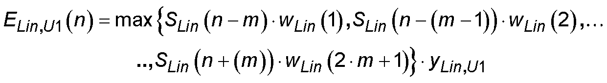
Zur Ermittlung einer oberen ersten Hüllkurve im Fall von linearen Ordinatenwerten wird hierbei jeder Ordinatenwert ELin,U1(n) der oberen ersten Hüllkurve gemäß Gleichung (1A) als Maximalwert aus einer bestimmten Anzahl 2·m+1 von jeweils benachbarten Ordinatenwerten SLin(n) des Frequenzspektrums ermittelt, die jeweils mit einer bestimmten Fensterfunktion wLin(n) gewichtet werden. E L i n , U 1 ( n ) = max { S L i n ( n m ) w L i n ( 1 ) , S L i n ( n ( m 1 ) ) w L i n ( 2 ) ,                         .., S L i n ( n + ( m ) ) w L i n ( 2 m + 1 ) } y L i n , U 1

Figure DE102010020910B4_0001
In order to obtain an upper first envelope in the case of linear ordinate values, each ordinate value E Lin, U1 (n) of the upper first envelope according to equation (1A) is expressed as the maximum value from a specific number 2 · m + 1 of adjacent ordinate values S Lin (n ) of the frequency spectrum, each weighted by a given window function w Lin (n). e L i n . U 1 ( n ) = Max { S L i n ( n - m ) w L i n ( 1 ) . S L i n ( n - ( m - 1 ) ) w L i n ( 2 ) . ... .., S L i n ( n + ( m ) ) w L i n ( 2 m + 1 ) } y L i n . U 1
Figure DE102010020910B4_0001

In einer anschließenden Funktionseinheit 41 zum Gewichten der ermittelten Ordinatenwerte der ersten Hüllkurve mit einem Gewichtungsfaktor wird der ermittelte Maximalwert mit einem Gewichtungsfaktor YLin,U1 multiplikativ gewichtet, um die Ordinatenwerte ELin,U1(n) der oberen ersten Hüllkurve an eine passende vertikale Position relativ zur vertikalen Position der Ordinatenwerte des Frequenzspektrums zu verschieben.In a subsequent functional unit 4 1 for weighting the ascertained ordinate values of the first envelope with a weighting factor, the ascertained maximum value is multiplicatively weighted with a weighting factor Y Lin, U1 by the ordinate values E Lin, U1 (n) of the upper first envelope to a suitable vertical position relative to the vertical position of the ordinate values of the frequency spectrum.

Bei Vorliegen von logarithmierten Ordinatenwerten ergibt sich jeder einzelne Ordinatenwert ELog,U1(n) der oberen ersten Hüllkurve gemäß Gleichung (2A) als Maximalwert aus einer bestimmten Anzahl 2·m+1 von jeweils benachbarten Ordinatenwerten SLog(n) des logarithmierten Frequenzspektrums, die jeweils mit einer bestimmten Fensterfunktion wLog(n) additiv verknüpft werden. Schließlich wird der ermittelte Maximalwert mit einem Gewichtungsfaktor yLog,U1 additiv verknüpft, um die Ordinatenwerte ELog,U1(n) der oberen ersten Hüllkurve an eine passende vertikale Position relativ zur vertikalen Position der Ordinatenwerte des Frequenzspektrums zu verschieben. E L o g , U 1 ( n ) = max { S L o g ( n m ) + w L o g ( 1 ) , S L o g ( n ( m 1 ) ) + w L o g ( 2 ) ,                         .., S L o g ( n + ( m ) ) w L o g ( 2 m + 1 ) } + y L o g , U 1

Figure DE102010020910B4_0002
In the case of logarithmic ordinate values, each individual ordinate value E Log, U1 (n) of the upper first envelope results according to equation (2A) as the maximum value from a specific number 2 * m + 1 of adjacent ordinate values S Log (n) of the logarithmic frequency spectrum. which are each additively linked to a specific window function w Log (n). Finally, the determined maximum value is additively linked to a weighting factor y Log, U1 to shift the ordinate values E Log, U1 (n) of the upper first envelope to an appropriate vertical position relative to the vertical position of the ordinate values of the frequency spectrum. e L O G . U 1 ( n ) = Max { S L O G ( n - m ) + w L O G ( 1 ) . S L O G ( n - ( m - 1 ) ) + w L O G ( 2 ) . ... .., S L O G ( n + ( m ) ) w L O G ( 2 m + 1 ) } + y L O G . U 1
Figure DE102010020910B4_0002

Die Ordinatenwerte ELin,D1(n) der unteren ersten Hüllkurve bei Vorliegen von linearen Ordinatenwerten ergeben sich gemäß Gleichung (1B) als Minimalwert aus einer bestimmten Anzahl 2·m+1 von jeweils benachbarten Ordinatenwerten SLin(n) des Frequenzspektrums, die jeweils mit einer bestimmten Fensterfunktion wLin(n) gewichtet werden, und die Ordinatenwerte ELog,D1(n) der unteren ersten Hüllkurve bei Vorliegen von logarithmierten Ordinatenwerten ergeben sich gemäß Gleichung (2B) als Minimalwert aus einer bestimmten Anzahl 2·m+1 von jeweils benachbarten Ordinatenwerten SLog(n) des Frequenzspektrums, die jeweils mit einer bestimmten Fensterfunktion wLog(n) gewichtet werden. Die vertikale Verschiebung des Minimalwerts erfolgt im Fall linearer Ordinatenwerte durch multiplikative Gewichtung mit dem Gewichtungsfaktor yLin,D1 und im Fall logarithmierter Ordinatenwerte durch additive Verknüpfung mit dem Gewichtungsfaktor yLog,D1· E L i n , D 1 ( n ) = min { S L i n ( n m ) w L i n ( 1 ) , S L i n ( n ( m 1 ) ) w L i n ( 2 ) ,                        .., S L i n ( n + ( m ) ) w L i n ( 2 m + 1 ) } y L i n , D 1

Figure DE102010020910B4_0003
E L o g , D 1 ( n ) = max { S L o g ( n m ) + w L o g ( 1 ) , S L o g ( n ( m 1 ) ) + w L o g ( 2 ) ,                   .., S L o g ( n + ( m ) ) + w L o g ( 2 m + 1 ) } y L o g , D 1
Figure DE102010020910B4_0004
The ordinate values E Lin, D1 (n) of the lower first envelope in the presence of linear ordinate values result according to equation (1B) as a minimum value of a certain number 2 · m + 1 of respectively adjacent ordinate values S Lin (n) of the frequency spectrum, respectively are weighted with a certain window function w Lin (n), and the ordinate values E Log, D1 (n) of the lower first envelope in the presence of logarithmic ordinates result according to equation (2B) as minimum value from a certain number 2 · m + 1 of each adjacent ordinate values S Log (n) of the frequency spectrum, each weighted by a particular window function w Log (n). The vertical displacement of the minimum value takes place in the case of linear ordinate values by multiplicative weighting with the weighting factor y Lin, D1 and in the case of logarithmic ordinate values by additive linking with the weighting factor y Log, D1 · e L i n . D 1 ( n ) = min { S L i n ( n - m ) w L i n ( 1 ) . S L i n ( n - ( m - 1 ) ) w L i n ( 2 ) . ... .., S L i n ( n + ( m ) ) w L i n ( 2 m + 1 ) } y L i n . D 1
Figure DE102010020910B4_0003
e L O G . D 1 ( n ) = Max { S L O G ( n - m ) + w L O G ( 1 ) . S L O G ( n - ( m - 1 ) ) + w L O G ( 2 ) . ... .., S L O G ( n + ( m ) ) + w L O G ( 2 m + 1 ) } y L O G . D 1
Figure DE102010020910B4_0004

Als Fensterfunktionen wLin(n) bzw. wLog(n) können gemäß 1 alle möglichen Fenstertypen, beispielsweise rechteckförmige, trapezförmige, dreiecksförmige oder parabelförmige Fensterfunktionen, verwendet werden. Abhängig vom Verlauf und der zeitlichen Charakteristik des Frequenzspektrums wird ein geeigneter Fenstertyp ausgewählt. Für Signale mit einem zeitinvarianten Träger kann typischerweise eine schmalbandige Fensterfunktion, beispielsweise eine parabelförmige Fensterfunktion, ausgewählt werden, während sich für Signale mit einem zeitveränderlichen Träger breitbandigere Fensterfunktionen, beispielsweise rechteckförmige oder trapezförmige Fensterfunktionen, eignen.As window functions w Lin (n) or w Log (n) can according to 1 all possible window types, for example rectangular, trapezoidal, triangular or parabolic window functions, can be used. Depending on the course and the temporal characteristics of the frequency spectrum becomes suitable window type selected. For signals with a time-invariant carrier, a narrow-band window function, for example a parabolic window function, can typically be selected, while broadband window functions, for example rectangular or trapezoidal window functions, are suitable for signals with a time-variant carrier.

Im nächsten Verfahrensschritt S20 werden die Ordinatenwerte ELin,U2(n) bzw. ELog,U2(n) der oberen zweiten Hüllkurve in Anlehnung an Gleichung (1A) bzw. (2A) und die Ordinatenwerte ELin,D2(n) bzw. ELog,D2(n) der unteren zweiten Hüllkurve in Anlehnung an Gleichung (1B) bzw. (2B) in einer Funktionseinheit 32 zum multiplikativen bzw. additiven Gewichten von Ordinatenwerten des Frequenzspektrums mit einer Fensterfunktion und in einer anschließenden Funktionseinheit 42 zum Gewichten der Ordinatenwerte der zweiten Hüllkurve mit einem Gewichtungsfaktor einer Funktionseinheit 2 zur Ermittlung einer zweiten Hüllkurve ermittelt. Hierbei sollten bevorzugt gemäß Gleichung (3A) bzw. (3B) alle Ordinatenwerte ELin,U2(n) bzw. ELog,U2(n) der oberen zweiten Hüllkurve größer oder gleich aller Ordinatenwerte ELin,U1(n) bzw. ELog,U1(n) der oberen ersten Hüllkurve und gemäß Gleichung (3C) bzw. (3D) alle Ordinatenwerte ELin,D2(n) bzw. ELog,D2(n) der unteren zweiten Hüllkurve kleiner oder gleich aller Ordinatenwerte ELin,D1(n) bzw. ELog,D1(n) der unteren ersten Hüllkurve sein. E L i n , U 2 ( n ) E L i n , U 1 ( n )

Figure DE102010020910B4_0005
E L o g , U 2 ( n ) E L o g , U 1 ( n )
Figure DE102010020910B4_0006
E L i n , D 1 ( n ) E L i n , D 2 ( n )
Figure DE102010020910B4_0007
E L o g , D 1 ( n ) E L o g , D 2 ( n )
Figure DE102010020910B4_0008
In the next process step S20 the ordinate values E Lin, U2 (n) and E Log, U2 (n) of the upper second envelope are based on equation (1A) or (2A) and the ordinate values E Lin, D2 (n) and E Log, respectively D2 (n) of the lower second envelope on the basis of equation (1B) or (2B) in a functional unit 3 2 for multiplicative or additive weighting of ordinate values of the frequency spectrum with a window function and in a subsequent functional unit 4 2 for weighting the ordinate values second envelope with a weighting factor of a functional unit 2 to determine a second envelope. In this case, according to equation (3A) or (3B), all ordinate values E Lin, U2 (n) and E Log, U2 (n) of the upper second envelope should preferably be greater than or equal to all ordinate values E Lin, U1 (n) and E, respectively Log, U1 (n) of the upper first envelope and according to Equation (3C) and (3D) all ordinate values E Lin, D2 (n) and E Log, D2 (n) of the lower second envelope less than or equal to all ordinate values E Lin , D1 (n) or E Log, D1 (n) of the lower first envelope. e L i n . U 2 ( n ) e L i n . U 1 ( n )
Figure DE102010020910B4_0005
e L O G . U 2 ( n ) e L O G . U 1 ( n )
Figure DE102010020910B4_0006
e L i n . D 1 ( n ) e L i n . D 2 ( n )
Figure DE102010020910B4_0007
e L O G . D 1 ( n ) e L O G . D 2 ( n )
Figure DE102010020910B4_0008

Für die Ermittlung der Ordinatenwerte ELin,U2(n) bzw. ELin,U2(n) bzw. ELin,D2(n) bzw. ELog,D2(n) der zweiten Hüllkurve wird vom Anwender ein anderer Fenstertyp der Fensterfunktion wLin(n) bzw. wLog(n) und/oder in einer Funktionseinheit 42 zum Gewichten der Ordinatenwerte der zweiten Hüllkurve mit einem Gewichtungsfaktor ein anderer Gewichtungsfaktor yLin,U2 bzw. yLog,U2 bzw. yLin,D2 bzw. yLog,D2 gegenüber der Ermittlung der Ordinatenwerte ELin,U1(n) bzw. ELog,U1(n) bzw. ELin,D1(n) bzw. ELog,D1(n) der ersten Hüllkurve verwendet.For the determination of the ordinate values E Lin, U2 (n) or E Lin, U2 (n) or E Lin, D2 (n) or E Log, D2 (n) of the second envelope curve, the user has another window type of the window function w Lin (n) or w log (n) and / or in a functional unit 4 2 for weighting the ordinate values of the second envelope with a weighting factor another weighting factor y Lin, U2 or y Log, U2 or y Lin, D2 or y Log, D2 compared to the determination of the ordinate values E Lin, U1 (n) or E Log, U1 (n) or E Lin, D1 (n) or E Log, D1 (n) of the first envelope used.

Im nächsten Verfahrensschritt S30 wird abgefragt, ob bei vorliegenden Rauschflur eine Rauschflur-Approximation am erfassten Frequenzspektrum bereits durchgeführt wurde.In the next process step S30 a query is made as to whether a noise floor approximation on the detected frequency spectrum has already been carried out with this noise floor.

Ist diese bei vorliegenden Rauschflur noch nicht ausgeführt worden, so erfolgt im nächsten Verfahrensschritt S40 in einem Approximator 6 zum Approximieren eines Rauschflurs ein Approximieren eines im erfassten Frequenzspektrum auftretenden Rauschflurs durch Ordinatenwerte des Frequenzspektrums, die auf einer horizontalen Gerade liegen. Hierzu werden über einen Schalter 5 bevorzugt die Ordinatenwerte der in den beiden vorherigen Verfahrensschritte S10 und S20 ermittelten ersten oberen Hüllkurve dem Approximator 6 zugeführt, aus denen gemäß dem Frequenzdiagramm in 3, in dem ein Frequenzspektrum mit einem Rauschflur dargestellt ist (durchgezogene Linie), der kleinste Ordinatenwert (Linie mit gefüllten Kreisen) ermittelt wird. Dieser kleinste Ordinatenwert der ersten oberen Hüllkurve dient als horizontaler Ordinatenwert für die Rauschflur-Approximation, der zusätzlich mit einem bestimmten Gewichtungsfaktor, typischerweise mit einem Gewichtungsfaktor in Höhe von 3 dB, gewichtet wird, um einen gewissen Mindestabstand zwischen dem Rauschflur im erfassten Frequenzspektrum und der Rauschflur-Approximation zu erzielen. Anschließend wird im selben Verfahrensschritt S30 im Approximator 6 das die ermittelte Rauschflur-Approximation enthaltende Frequenzspektrum erzeugt.If this has not yet been carried out in the case of the present noise floor, then in the next method step S40 in an approximator 6 for approximating a noise floor, approximating a noise floor occurring in the detected frequency spectrum by ordinate values of the frequency spectrum lying on a horizontal line. This will be done via a switch 5 prefers the ordinate values of the two previous method steps S10 and S20 determined first upper envelope of the approximator 6 from which according to the frequency diagram in 3 in which a frequency spectrum with a noise floor is shown (solid line), the smallest ordinate value (line with filled circles) is determined. This smallest ordinate value of the first upper envelope serves as a horizontal ordinate value for the noise floor approximation, which is additionally weighted with a certain weighting factor, typically with a weighting factor of 3dB, by a certain minimum distance between the noise floor in the detected frequency spectrum and the noise floor To achieve approximation. Subsequently, in the same process step S30 in the approximator 6 which generates the determined noise floor approximation containing frequency spectrum.

Aus dem die ermittelte Rauschflurapproximation enthaltenden Frequenzspektrum werden in den beiden Verfahrensschritten S10 und S20 wiederholt die Ordinatenwerte ELin,U1(n) bzw. ELog,U1(n) bzw. ELin,D1(n) bzw. ELog,D1(n) der ersten oberen und unteren Hüllkurve und die Ordinatenwerte ELin,U2(n) bzw. ELog,U2(n) bzw. ELin,D2(n) bzw. ELog,D2(n) der zweiten oberen und unteren Hüllkurve bestimmt.The frequency spectrum containing the determined noise floor approximation is determined in the two method steps S10 and S20 repeats the ordinate values E Lin, U1 (n) and E Log, U1 (n) and E Lin, D1 (n) and E Log, D1 (n) of the first upper and lower envelopes and the ordinate values E Lin, U2, respectively (E) or E Log, U2 (n) or E Lin, D2 (n) or E Log, D2 (n) of the second upper and lower envelope.

Nach Ermittlung der ersten und zweiten Hüllkurven des die ermittelte Rauschflurapproximation enthaltenden Frequenzspektrums wird im nächsten Verfahrensschritt S50 in einer Funktionseinheit 8 zur Ermittlung von Ordinatenwerten einer zwischen erster und zweiter Hüllkurve befindlichen Frequenzmaske eine obere und/oder untere Frequenzmaske ermittelt, die sich jeweils innerhalb der jeweiligen ersten und zweiten Hüllkurve oberhalb bzw. unterhalb der Ordinatenwerte des erfassten Frequenzspektrums befindet.After determining the first and second envelopes of the frequency noise spectrum containing the determined noise floor approximation, in the next method step S50 in a functional unit 8th For determining ordinate values of a frequency mask located between the first and second envelope, an upper and / or lower frequency mask is determined, which is located within the respective first and second envelope above or below the ordinate values of the detected frequency spectrum.

Hierzu wird in einem Unterverfahren zur Ermittlung der Ordinatenwerte der Frequenzmaske aus den Ordinatenwerten der ersten und zweiten Hüllkurve gemäß dem Flussdiagramm in 13 in einem ersten Unterverfahrensschritt S100 der Ordinatenwert der ersten oder zweiten Hüllkurve am linken oder rechten Rand des Frequenzspektrums als ersten im Unterverfahren zu untersuchender Ordinatenwert ausgewählt und eine Variable „aktueller Ordinatenwert“ mit dem ausgewählten Ordinatenwert belegt. For this purpose, in a sub-method for determining the ordinate values of the frequency mask from the ordinate values of the first and second envelopes according to the flowchart in FIG 13 in a first sub-process step S100 the ordinate value of the first or second envelope at the left or right edge of the frequency spectrum is selected as the first ordinate value to be examined in the sub-method, and a variable "current ordinate value" is assigned the selected ordinate value.

Im nächsten Unterverfahrensschritt S110 werden sämtliche Metriken und Variablen des ersten zu untersuchenden Ordinatenwerts und aller folgenden zu untersuchenden Ordinatenwerte initialisiert.In the next sub-process step S110 all the metrics and variables of the first ordinate value to be examined and all subsequent ordinate values to be examined are initialized.

Für den ersten zu untersuchenden Ordinatenwert wird eine Metrik-Variable ShortestPathNofNodes, die die Anzahl von Ordinatenwerten auf dem kürzesten Pfad vom linken bzw. rechten Rand des Frequenzspektrums zum aktuell zu untersuchenden Ordinatenwert beinhaltet, mit dem Wert Null belegt. Für alle folgenden zu untersuchenden Ordinatenwerte wird die Metrik-Variable ShortestPathNofNodes mit dem Wert Unendlich belegt.For the first ordinate value to be examined, zero is assigned to a metric variable ShortestPathNofNodes, which contains the number of ordinate values on the shortest path from the left or right edge of the frequency spectrum to the ordinate value to be examined. For all subsequent ordinate values to be examined, the metric variable ShortestPathNofNodes is assigned the value Infinity.

Eine weitere Metrik-Variable ShortestPathlength, die die Länge des kürzesten Pfades vom linken bzw. rechten Rand des Frequenzspektrums zum aktuell zu untersuchenden Ordinatenwert beinhaltet, wird für den ersten zu untersuchenden Ordinatenwert mit dem Wert Null und für alle folgenden zu untersuchenden Ordinatenwerte mit dem Wert Unendlich belegt.Another metric variable ShortestPathlength, which contains the length of the shortest path from the left or right edge of the frequency spectrum to the ordinate value to be examined, becomes zero for the first ordinate value to be examined and for all subsequent ordinate values to be examined with the value infinity busy.

Schließlich wird eine Variable PredecessorNode, die den Vorgänger-Ordinatenwert des aktuell zu untersuchenden Ordinatenwerts auf dem kürzesten Pfad vom linken bzw. rechten Rand des Frequenzspektrums zum aktuell zu untersuchenden Ordinatenwert beinhaltet, mit dem Wert „Keiner“ belegt.Finally, a variable PredecessorNode, which contains the predecessor ordinate value of the ordinate value currently to be examined on the shortest path from the left or right edge of the frequency spectrum to the ordinate value to be examined, is assigned the value "none".

Im nächsten Unterverfahrensschritt S120 werden alle Ordinatenwerte der ersten und zweiten Hüllkurve ermittelt, die vom aktuell zu untersuchenden Ordinatenwert durch eine lineare Verbindung innerhalb der ersten und zweiten Hüllkurve erreichbar sind.In the next sub-process step S120 all ordinate values of the first and second envelope are determined, which can be obtained from the ordinate value currently to be examined by a linear connection within the first and second envelope.

Im darauffolgenden Unterverfahrensschritt S130 werden alle Variablen jedes Ordinatenwerts der ersten und/oder zweiten Hüllkurve, der vom aktuellen Ordinatenwert erreichbar ist, im Hinblick auf den aktuell ermittelten Pfad, der sich vom Rand des Frequenzspektrums bis zum erreichbaren Ordinatenwert erstreckt, berechnet.In the subsequent sub-process step S130 For example, all variables of each ordinate value of the first and / or second envelope achievable from the current ordinate value are calculated with respect to the currently determined path extending from the edge of the frequency spectrum to the reachable ordinate value.

Die Metrik-Variable ShortestPathNofNodes für jeden erreichbaren Ordinatenwert der ersten und/oder zweiten Hüllkurve ergibt sich für den aktuell ermittelten Pfad aus dem um den Wert 1 inkrementierten Wert der Metrik-Variable ShortestPathNofNodes des aktuell zu analysierenden Ordinatenwerts.The metric variable ShortestPathNofNodes for each achievable ordinate value of the first and / or second envelope results for the currently determined path from that around the value 1 incremented value of the metric variable ShortestPathNofNodes of the ordinate value currently being parsed.

Die Metrik-Variable ShortestPathlength für jeden erreichbaren Ordinatenwert der ersten und/oder zweiten Hüllkurve ergibt sich für den aktuell ermittelten Pfad aus dem Wert der Metrik-Variable ShortestPathlength des aktuell zu analysierenden Ordinatenwerts zuzüglich des Abstands zwischen dem jeweilig erreichbaren Ordinatenwert und dem aktuell zu analysierenden Ordinatenwert.The metric variable ShortestPathlength for each achievable ordinate value of the first and / or second envelope results for the currently determined path from the value of the metric variable ShortestPathlength of the ordinate value currently to be analyzed plus the distance between the respective achievable ordinate value and the ordinate value currently to be analyzed ,

Die Variable „Vorgänger-Ordinatenwert“ für jeden erreichbaren Ordinatenwert der ersten und/oder zweiten Hüllkurve ergibt sich für den aktuell ermittelten Pfad aus dem aktuell zu analysierenden Ordinatenwert.The variable "predecessor ordinate value" for each achievable ordinate value of the first and / or second envelope results for the currently determined path from the ordinate value currently to be analyzed.

Nur für den Fall, dass der für den jeweilig erreichbaren Ordinatenwert berechnete Wert der Metrik-Variable ShortestPathNofNodes kleiner als der jeweilig abgespeicherte Wert der Metrik-Variable ShortestPathNofNodes ist, also für den Fall, dass ein Pfad mit weniger Punkten ermittelt wurde, werden die Variablen ShortestPathNofNodes, ShortestPathlength und „Vorgänger-Ordinatenwert“ des jeweilig erreichbaren Ordinatenwert mit den jeweiligen im vorherigen Unterverfahrensschritt S130 ermittelten Werten aktualisiert.Only in the event that the value of the metric variable ShortestPathNofNodes calculated for the respective achievable ordinate value is smaller than the respectively stored value of the metric variable ShortestPathNofNodes, ie in the case where a path with fewer points has been determined, are the variables ShortestPathNofNodes , ShortestPathlength and "Predecessor ordinate value" of the respective achievable ordinate value with the respective ones in the previous sub-process step S130 updated values.

Im Fall, dass der für den jeweilig erreichbaren Ordinatenwert berechnete Wert der Metrik-Variable ShortestPathNofNodes identisch zum jeweilig abgespeicherten Wert der Metrik-Variable ShortestPathNofNodes ist, wird der für den jeweilig erreichbaren Ordinatenwert berechnete Wert der Metrikvariable ShortestPathlength mit dem für den jeweilig erreichbaren Ordinatenwert abgespeicherten Wert der Metrik-Variable ShortestPathlength verglichen und werden diejenigen Variablen ShortestPathNofNodes, ShortestPathlength und „Vorgänger-Ordinatenwert“ für den jeweilig erreichbaren Ordinatenwert weiterverfolgt d.h. abgespeichert, die zu dem Pfad mit der kürzeren Pfadlänge gehören.In the event that the value of the metric variable ShortestPathNofNodes calculated for the respectively achievable ordinate value is identical to the respectively stored value of the metric variable ShortestPathNofNodes, the value calculated for the respective achievable ordinate value is the metric variable ShortestPathlength with the value stored for the respectively achievable ordinate value the metric variable ShortestPathlength is compared and those variables ShortestPathNofNodes, ShortestPathlength and "Predecessor Ordinatenwert" for the respective achievable ordinate value are tracked ie stored belonging to the path with the shorter path length.

Im nächsten Unterverfahrensschritt S150 wird überprüft, ob der in der Variablen „aktueller Ordinatenwert“ gespeicherte und aktuell zu untersuchende Ordinatenwert der ersten oder zweiten Hüllkurve bereits der Ordinatenwert der ersten oder zweiten Hüllkurve am jeweiligen anderen Rand des erfassten Frequenzspektrums ist. Ist dies noch nicht der Fall, d.h. der aktuell zu analysierende Ordinatenwert der ersten oder zweiten Hüllkurve ist entweder der Ordinatenwert am startenden Rand des erfassten Frequenzspektrums oder ein Ordinatenwert zwischen dem startenden und dem endenden Rand des erfassten Frequenzspektrums, so wird im nächsten Unterverfahrensschritt S160 entweder der Ordinatenwert beim gleichen Abtastfrequenzwert der jeweils anderen Hüllkurve - erste oder zweite Hüllkurve - zum aktuell zu analysierenden Ordinatenwert ausgewählt, falls dies noch nicht geschehen ist, oder die Variable „aktueller Ordinatenwert,, um den Wert 1 inkrementiert und somit der benachbarte Ordinatenwert der ersten oder zweiten Hüllkurve in Richtung des endenden Rands des erfassten Frequenzspektrums zum aktuell zu analysierenden Ordinatenwert ausgewählt und die Analyse für diesen neu zu analysierenden Ordinatenwert in den Unterverfahrensschritten S120, S130 und S140 fortgesetzt. In the next sub-process step S150 it is checked whether the ordinate value of the first or second envelope stored in the variable "current ordinate value" and currently to be examined is already the ordinate value of the first or second envelope at the respective other edge of the detected frequency spectrum. If this is not yet the case, ie the ordinate value of the first or second envelope currently to be analyzed is either the ordinate value at the starting edge of the detected frequency spectrum or an ordinate value between the starting and ending edge of the detected frequency spectrum, then in the next sub-process step S160 either the ordinate value at the same sampling frequency value of the respective other envelope curve - first or second envelope - selected for the currently analyzed ordinate value, if this has not already been done, or the variable "current ordinate value" by the value 1 and thus the adjacent ordinate value of the first or second envelope in the direction of the ending edge of the detected frequency spectrum is selected for the ordinate value currently to be analyzed, and the analysis for this ordinate value to be re-analyzed in the sub-method steps S120 . S130 and S140 continued.

Für den Fall, dass der aktuell zu analysierende Ordinatenwert der ersten oder zweiten Hüllkurve dem Ordinatenwert der ersten oder zweiten Hüllkurve am endenden Rand des erfassten Frequenzspektrums entspricht, so ist die Analyse abgeschlossen. In diesem Fall werden im abschließenden Unterverfahrensschritt S170 die Ordinatenwerte der Frequenzmaske ermittelt, indem ausgehend von demjenigen Ordinatenwert der ersten oder zweiten Hüllkurve am endenden Rand des erfassten Frequenzspektrums, das den niedrigsten Wert der Metrik-Variable ShortestPathLength aufweist und damit die kürzeste Pfadlänge zu einem Ordinatenwert der ersten oder zweiten Hüllkurve am startenden Rand des erfassten Frequenzspektrums aufweist, sukzessive die jeweils im Pfad vorausgehenden Ordinatenwerte der ersten oder zweiten Hüllkurve über die Belegung der Variable „Vorgänger-Ordinatenwert“ des jeweils nachfolgenden Ordinatenwerts der ersten oder zweiten Hüllkurve ermittelt werden.In the event that the ordinate value of the first or second envelope currently to be analyzed corresponds to the ordinate value of the first or second envelope at the ending edge of the detected frequency spectrum, then the analysis is complete. In this case, in the final sub-process step S170 the ordinate values of the frequency mask are determined by starting from the ordinate value of the first or second envelope at the ending edge of the detected frequency spectrum having the lowest value of the metric variable ShortestPathLength and thus the shortest path length to an ordinate value of the first or second envelope at the starting edge of the Having detected frequency spectrum, successively each preceding in the path ordinate values of the first or second envelope on the assignment of the variable "predecessor ordinate" of the respective subsequent ordinate value of the first or second envelope are determined.

Das Ergebnis einer derartigen Ermittlung der Ordinatenwerte der Frequenzmaske kann dem Frequenzdiagramm der 2 entnommen werden, in dem für ein erfasstes Frequenzspektrum eine erste und zweite obere Hüllkurve dargestellt ist. Die erste und zweite Hüllkurve bilden die beiden Begrenzungen eines schraffiert dargestellten Korridors, in dem die zu ermittelnde Frequenzmaske liegt, deren Ordinatenwerte entweder Ordinatenwerte der ersten Hüllkurve und/oder Ordinatenwerte der zweiten Hüllkurve sind.The result of such determination of the ordinate values of the frequency mask can be found in the frequency diagram of FIG 2 are taken, in which for a detected frequency spectrum, a first and second upper envelope is shown. The first and second envelopes form the two boundaries of a hatched corridor in which lies the frequency mask to be determined whose ordinate values are either ordinate values of the first envelope and / or ordinate values of the second envelope.

Das im Verfahrensschritt S60 enthaltene Unterverfahren zur Optimierung der Frequenzmaske in der Umgebung von Maxima bzw. Minima, das im Verfahrensschritt S70 enthaltene Unterverfahren zur Optimierung der Frequenzmaske im Übergangsbereich zwischen Rauschflur und dem an den Rauschflur angrenzenden Frequenzbereich sowie das im Verfahrensschritt S80 enthaltene Unterverfahren zur Optimierung der Frequenzmaske im Bereich der Flanken werden weiter unten im Detail erläutert.The in process step S60 contained sub-method for optimizing the frequency mask in the vicinity of maxima or minima, in the process step S70 contained sub-method for optimizing the frequency mask in the transition region between noise floor and adjacent to the noise floor frequency range as well as in the process step S80 Submethods for optimizing the frequency mask in the area of the flanks are explained in detail below.

Im Folgenden wird das zweite Ausführungsbeispiel des erfindungsgemäßen Verfahrens zur Ermittlung einer Frequenzmaske für ein Frequenzspektrum anhand des Flussdiagramms in 12B und das zugehörige zweite Ausführungsbeispiel der erfindungsgemäßen Vorrichtung zur Ermittlung einer Frequenzmaske für ein Frequenzspektrum in 15B erläutert.In the following, the second exemplary embodiment of the method according to the invention for determining a frequency mask for a frequency spectrum will be described with reference to the flowchart in FIG 12B and the associated second embodiment of the inventive device for determining a frequency mask for a frequency spectrum in 15B explained.

Im ersten Verfahrensschritt S200 wird in einer Funktionseinheit zum Auswählen des ersten Ordinatenwerts der Frequenzmaske 10 ein Ordinatenwert am linken oder rechten Rand des erfassten Frequenzspektrums als erster Ordinatenwert der Frequenzmaske ausgewählt.In the first process step S200 is set in a functional unit for selecting the first ordinate value of the frequency mask 10 an ordinate value at the left or right edge of the detected frequency spectrum is selected as the first ordinate value of the frequency mask.

Ausgehend von diesem ersten Ordinatenwert der Frequenzmaske wird im darauffolgenden Verfahrensschritt S210 in einer Funktionseinheit 11 zum sukzessiven Ermitteln des jeweils nächsten Ordinatenwerts der Frequenzmaske der jeweils nächste Ordinatenwert der Frequenzmaske aus den Ordinatenwerten des erfassten Frequenzspektrums ermittelt, der am weitesten vom jeweils zuletzt ermittelten Ordinatenwert der Frequenzmaske entfernt liegt. Als zusätzliche Bedingung für die Auswahl des nächsten Ordinatenwerts der Frequenzmaske muss gelten, dass sämtliche Ordinatenwerte des erfassten Frequenzspektrums, deren zugehörige Abtastfrequenzwerte zwischen dem Abtastfrequenzwert des zuletzt ermittelten Ordinatenwerts der Frequenzmaske und dem Abtastfrequenzwert des nächsten zu ermittelnden Ordinatenwerts der Frequenzmaske liegen, jeweils einen vertikalen Abstand zu der Verbindungslinie zwischen dem zuletzt ermittelten und dem nächsten zu ermittelnden Ordinatenwert der Frequenzmaske aufweisen, der kleiner als ein vorgegebener Schwellwert ist.Starting from this first ordinate value of the frequency mask is in the subsequent process step S210 in a functional unit 11 for successively determining the respective next ordinate value of the frequency mask, the respective next ordinate value of the frequency mask is determined from the ordinate values of the detected frequency spectrum which is farthest from the respectively last ordinate value of the frequency mask determined. As an additional condition for the selection of the next ordinate value of the frequency mask, all ordinate values of the detected frequency spectrum whose associated sampling frequency values lie between the sampling frequency value of the last ascertained ordinate value of the frequency mask and the sampling frequency value of the next ordinate value of the frequency mask to be determined each have a vertical distance the connection line between the last determined and the next to be determined ordinate value of the frequency mask, which is smaller than a predetermined threshold value.

Die Vorgehensweise des Verfahrensschritts S210 ist beispielhaft in den 4A bis 4D dargestellt. In 4A wird der am linken Rand des Frequenzspektrums befindliche Ordinatenwert P1 als erster Ordinatenwert der Frequenzmaske ausgewählt. Das Kreuz dient als Kennzeichen für die Auswahl eines Ordinatenwerts des Frequenzspektrums zum Ordinatenwert der Frequenzmaske. Da der Ordinatenwert P2 des Frequenzspektrums einen vertikalen Abstand zur Verbindungslinie zwischen dem zuletzt als Ordinatenwert der Frequenzmaske ausgewählten Ordinatenwert P1 und dem potentiell als nächsten Ordinatenwert der Frequenzmaske auszuwählenden Ordinatenwert P3 aufweist, der kleiner als der durch die gestrichelte Linie dargestellte Schwellwert ist, kann in einem nächsten, in 4B dargestellten Schritt der Ordinatenwert P4, der gegenüber dem Ordinatenwert P3 einen größeren Abstand zum zuletzt ausgewählten Ordinatenwert P1 der Frequenzmaske aufweist, für seine Eignung als potentieller nächster Ordinatenwert der Frequenzmaske untersucht werden.The procedure of the process step S210 is exemplary in the 4A to 4D shown. In 4A becomes the ordinate value located at the left edge of the frequency spectrum P1 first Ordinate value of the frequency mask selected. The cross serves as a mark for selecting an ordinate value of the frequency spectrum to the ordinate value of the frequency mask. Since the ordinate value P2 of the frequency spectrum is a vertical distance to the connecting line between the ordinate value last selected as the ordinate value of the frequency mask P1 and the ordinate value to be potentially selected as the next ordinate value of the frequency mask P3 , which is smaller than the threshold value represented by the dashed line, may in a next, in 4B step shown the ordinate value P4 , the opposite of the ordinate value P3 a greater distance to the last selected ordinate value P1 the frequency mask has been examined for its suitability as a potential next ordinate value of the frequency mask.

Da auch in diesem Schritt die zwischen dem zuletzt ausgewählten Ordinatenwert P1 der Frequenzmaske und dem potentiell als nächsten Ordinatenwert der Frequenzmaske auszuwählenden Ordinatenwert P4 hinsichtlich ihrer Abtastfrequenzwerte liegenden Ordinatenwerte P2 und P3 einen gegenüber dem Schwellwert kleineren vertikalen Abstand zur Verbindungslinie zwischen den beiden Ordinatenwerten P1 und P4 aufweisen, muss in einem weiteren in 4C dargestellten Schritt der Ordinatenwert P5 hinsichtlich seiner Eignung als nächster Ordinatenwert der Frequenzmaske untersucht werden. Da bei einer Verbindungslinie zwischen dem zuletzt als Ordinatenwert der Frequenzmaske ausgewählten Ordinatenwert P1 und dem potentiell als nächsten Ordinatenwert der Frequenzmaske auszuwählenden Ordinatenwert P5 der Ordinatenwert P3 liegt, dessen vertikaler Abstand zur Verbindungslinie größer als der in 4C dargestellte Schwellwert ist, wird nicht der Ordinatenwert P5, sondern der Ordinatenwert P4, wie in 4D dargestellt ist, als nächster Ordinatenwert der Frequenzmaske ausgewählt.As in this step, the between the last selected ordinate value P1 the frequency mask and the ordinate value to be optionally selected as the next ordinate value of the frequency mask P4 with respect to their sampling frequency values, ordinate values P2 and P3 a smaller relative to the threshold vertical distance to the connecting line between the two ordinate values P1 and P4 must have in another in 4C step shown the ordinate value P5 in terms of its suitability as the next ordinate value of the frequency mask. Since at a connecting line between the ordinate value last selected as the ordinate value of the frequency mask P1 and the ordinate value to be potentially selected as the next ordinate value of the frequency mask P5 the ordinate value P3 whose vertical distance to the connecting line is greater than that in 4C is not the ordinate value P5 but the ordinate value P4 , as in 4D is selected as the next ordinate value of the frequency mask.

Im abschließenden Verfahrensschritt S220 werden in einer Funktionseinheit 12 zum Erzeugen der oberhalb und unterhalb des Frequenzspektrums befindlichen Frequenzmaske die somit ermittelten Ordinatenwerte der Frequenzmaske durch Gewichtung mit jeweils einem Gewichtungsfaktor soweit vertikal verschoben, dass jeweils eine obere und untere Frequenzmaske entsteht, die in einem bestimmten vertikalen Abstand zum erfassten Frequenzspektrum zu liegen kommt.In the final process step S220 be in a functional unit 12 in order to generate the frequency mask located above and below the frequency spectrum, the ordinate values of the frequency mask thus determined are shifted vertically by weighting, each with a weighting factor, such that an upper and lower frequency mask results which lies at a certain vertical distance from the detected frequency spectrum.

Das im Verfahrensschritt S230 enthaltene Unterverfahren zur Optimierung der Frequenzmaske in der Umgebung von Maxima bzw. Minima, das im Verfahrensschritt S240 enthaltene Unterverfahren zur Optimierung der Frequenzmaske im Übergangsbereich zwischen Rauschflur und dem an den Rauschflur angrenzenden Frequenzbereich sowie das im Verfahrensschritt S250 enthaltene Unterverfahren zur Optimierung der Frequenzmaske im Bereich der Flanken werden weiter unten im Detail erläutert.The in process step S230 contained sub-method for optimizing the frequency mask in the vicinity of maxima or minima, in the process step S240 contained sub-method for optimizing the frequency mask in the transition region between noise floor and adjacent to the noise floor frequency range as well as in the process step S250 Submethods for optimizing the frequency mask in the area of the flanks are explained in detail below.

In 5 ist das erfasste Frequenzspektrum (durchgezogene Linie) und die mit dem zweiten Ausführungsbeispiel des erfindungsgemäßen Verfahrens bzw. mit der zweiten Ausführungsform der erfindungsgemäßen Vorrichtung ermittelte Frequenzmaske (Linie mit Quadraten) dargestellt.In 5 is the detected frequency spectrum (solid line) and with the second embodiment of the method according to the invention or with the second embodiment of the inventive device determined frequency mask (line with squares) shown.

Im Folgenden wird das Unterverfahren zur Optimierung der Frequenzmaske in der Umgebung von Maxima bzw. Minima im Detail anhand des Flussdiagramms in 14A sowie die zugehörige Funktionseinheit 20 zum Ermitteln einer Näherungsfunktion in der Umgebung von Maxima bzw. Minima in 16A beschrieben.In the following, the sub-procedure for optimizing the frequency mask in the vicinity of maxima or minima is described in detail with reference to the flowchart in FIG 14A as well as the associated functional unit 20 for determining an approximation function in the vicinity of maxima or minima in 16A described.

Im ersten Unterverfahrensschritt S300 werden in der Funktionseinheit 21 zum Identifizieren von Maxima bzw. Minima in der Frequenzmaske anhand der im Verfahrensschritt S50 des ersten erfindungsgemäßen Verfahrens zur Ermittlung einer Frequenzmaske für ein Frequenzspektrum oder anhand der im Verfahrensschritt S220 des zweiten erfindungsgemäßen Verfahrens zur Ermittlung einer Frequenzmaske für ein Frequenzspektrum ermittelten Ordinatenwerte der Frequenzmaske die in der Frequenzmaske auftretenden lokalen Maxima und/oder lokalen Minima identifiziert. Hierzu wird in jedem ermittelten Ordinatenwert der Frequenzmaske ermittelt, ob die erste Ableitung Null - Kriterium für ein Extremum - und ob die zweite Ableitung größer oder kleiner als Null - Kriterium für ein Minimum bzw. ein Maximum - ist. In 6A sind die ermittelten lokalen Maxima der Ordinatenwerte der Frequenzmaske und in 8A sind die ermittelten lokalen Minima der Ordinatenwerte der Frequenzmaske durch einen Pfeil gekennzeichnet.In the first sub-process step S300 be in the functional unit 21 for identifying maxima or minima in the frequency mask on the basis in the method step S50 of the first method according to the invention for determining a frequency mask for a frequency spectrum or on the basis of the method step S220 of the second method according to the invention for determining a frequency mask for ordinate values of the frequency mask determined for a frequency spectrum, identifies the local maxima and / or local minima occurring in the frequency mask. For this purpose, it is determined in each determined ordinate value of the frequency mask whether the first derivative is zero - criterion for an extremum - and whether the second derivative is greater or less than zero - criterion for a minimum or a maximum. In 6A are the determined local maxima of the ordinate values of the frequency mask and in 8A the determined local minima of the ordinate values of the frequency mask are indicated by an arrow.

Im nächsten Unterverfahrensschritt S310 werden in der Funktionseinheit 22 zum Ermitteln aller Ordinatenwerte der Frequenzmaske in der Umgebung von Maxima und Minima alle Ordinatenwerte der Frequenzmaske in der Umgebung des Maximums bzw. Minimums ermittelt. Gemäß 6B werden hierzu alle Ordinatenwerte der Frequenzmaske ermittelt, die zwischen einer Horizontalen durch das jeweils identifizierte lokale Maximum (Linie mit Dreiecken) und einer Horizontalen durch einen Schwellwert unterhalb des jeweils identifizierten lokalen Maximums - in 6B eine Horizontale bei einem Schwellwert, der 3 dB unterhalb des jeweils identifizierten lokalen Maximums liegt (Linie mit Kreuzen) - liegen.In the next sub-process step S310 be in the functional unit 22 For determining all ordinate values of the frequency mask in the vicinity of maxima and minima, all ordinate values of the frequency mask in the vicinity of the maximum or minimum are determined. According to 6B For this purpose, all ordinate values of the frequency mask are determined, which lie between a horizontal line through the respectively identified local maximum (line with triangles) and a horizontal line through a threshold below the respectively identified local maximum - 6B a horizontal at a threshold which is 3 dB below the respectively identified local maximum (line with crosses) - lie.

Im nächsten Unterverfahrensschritt S320 werden in der Funktionseinheit 23 zum Ermitteln von Funktionstyp und Funktionsparametern der Näherungsfunktion der Funktionstyp und die Funktionsparameter der Näherungsfunktion für die ermittelte Frequenzmaske in der Umgebung des Maximums bzw. Minimums bestimmt. Hierzu wird eine Metrik, beispielsweise die Fehlerquadrate oder die Fehlerbeträge, zwischen den in der Umgebung des Maximums bzw. Minimums ermittelten Ordinatenwerten der Frequenzmaske und den im gleichen Frequenzbereich positionierten Ordinatenwerten der zu bestimmenden Näherungsfunktion ermittelt und minimiert. In the next sub-process step S320 be in the functional unit 23 for determining function type and function parameters of the approximation function, the function type and the function parameters of the approximation function for the determined frequency mask are determined in the environment of the maximum or minimum. For this purpose, a metric, for example the error squares or the error amounts, between the ordinate values of the frequency mask determined in the vicinity of the maximum or minimum and the ordinate values of the approximation function to be determined in the same frequency range is determined and minimized.

Für die Ordinatenwerte der Näherungsfunktion gilt, dass sie alle im Fall eines Maximums entweder oberhalb der Ordinatenwerte der Frequenzmaske oder innerhalb eines bestimmten Toleranzbereichs unterhalb der Ordinatenwerte der Frequenzmaske und im Fall eines Minimums entweder unterhalb der Ordinatenwerte der Frequenzmaske oder innerhalb eines bestimmten Toleranzbereichs oberhalb der Ordinatenwerte der Frequenzmaske zu liegen kommen. Außerdem müssen alle Ordinatenwerte der Näherungsfunktion im Fall eines Maximums oberhalb der Ordinatenwerte der ersten Hüllkurve und im Fall eines Minimums unterhalb der Ordinatenwerte der ersten Hüllkurve liegen. Die Näherungsfunktion mit ihren Ordinatenwerten ist für den Fall eines Maximums in 6C und für den Fall eines Minimums in 8B als Linie mit Quadraten dargestellt.For the ordinate values of the approximation function, they are all either in the case of a maximum above the ordinate values of the frequency mask or within a certain tolerance range below the ordinate values of the frequency mask and in the case of a minimum either below the ordinate values of the frequency mask or within a certain tolerance range above the ordinate values of the frequency mask Frequency mask come to rest. Moreover, in the case of a maximum, all ordinate values of the approximation function must be above the ordinate values of the first envelope and, in the case of a minimum, below the ordinate values of the first envelope. The approximation function with its ordinate values is in the case of a maximum in 6C and in the case of a minimum in 8B shown as a line with squares.

Im abschließenden Unterverfahrensschritt S330 wird in einer Funktionseinheit 24 zum Ermitteln einer reduzierten Anzahl von Ordinatenwerten der Näherungsfunktion die ermittelte Nährungsfunktion durch charakteristische Punkte genähert. Diese charakteristischen Punkte können bei einer parabelförmigen Näherungsfunktion in der Umgebung eines Maximums im Maximum der parabelförmigen Näherungsfunktion, bei einem ersten Schwellwert unterhalb des Maximums, beispielsweise bei einem Schwellwert 1 dB unterhalb des Maximums, und bei einem zweiten Schwellwert unterhalb des Maximums, beispielsweise bei einem Schwellwert 3 dB unterhalb des Maximums liegen. Bei einer parabelförmigen Näherungsfunktion in der Umgebung eines Minimums können diese charakteristischen Punkte im Minimum der parabelförmigen Näherungsfunktion, bei einem ersten Schwellwert oberhalb des Minimums, beispielsweise bei einem Schwellwert 1 dB oberhalb des Minimums, und bei einem zweiten Schwellwert oberhalb des Minimums, beispielsweise bei einem Schwellwert 3 dB oberhalb des Minimums liegen. Die ursprünglich ermittelten Ordinatenwerte der Frequenzmaske werden schließlich durch die charakteristischen Punkte der Näherungsfunktion ersetzt, wie in 6D durch die Linie mit Quadraten dargestellt ist.In the final sub-process step S330 is in a functional unit 24 for determining a reduced number of ordinate values of the approximation function, approximating the determined approximation function by characteristic points. With a parabolic approximation function in the vicinity of a maximum, these characteristic points can be at the maximum of the parabolic approximation function, at a first threshold value below the maximum, for example at a threshold value of 1 dB below the maximum, and at a second threshold value below the maximum, for example at a threshold value 3 dB below the maximum. For a parabolic approximation near a minimum, these characteristic points may be at the parabola approximation, at a first threshold above the minimum, for example at a threshold 1 dB above the minimum, and at a second threshold above the minimum, at a threshold, for example 3 dB above the minimum. The originally determined ordinate values of the frequency mask are finally replaced by the characteristic points of the approximation function, as in 6D represented by the line with squares.

Kommen die charakteristischen Punkte der Näherungsfunktion nicht auf einen der Abtastfrequenzwerte der ermittelten Ordinatenwerte der Frequenzmaske zu liegen, so kann der charakteristische Punkt der Näherungsfunktion durch einen alternativen charakteristischen Punkt der Näherungsfunktion beim rechts- oder linksseitig am nächsten gelegenen Abtastfrequenzwert ersetzt werden.If the characteristic points of the approximation function do not coincide with one of the sampling frequency values of the determined ordinate values of the frequency mask, the characteristic point of the approximation function can be replaced by an alternative characteristic point of the approximation function at the sampling frequency value located on the right or left side.

Bei einer trapezförmigen Näherungsfunktion wird nach Ermittlung des jeweiligen lokalen Maximums bzw. lokalen Minimums im Verlauf der Ordinatenwerte der Frequenzmaske gemäß Unterverfahrensschritt S300 der Schnittpunkt einer ersten Schwelle und einer zweiten Schwelle unterhalb des ermittelten lokalen Maximums mit dem Verlauf der Ordinatenwerte der Frequenzmaske bzw. der Schnittpunkt einer ersten Schwelle und einer zweiten Schwelle oberhalb des ermittelten lokalen Minimums mit dem Verlauf der Ordinatenwerte der Frequenzmaske gesucht. Als Schwellwerte für die erste und zweite Schwelle können beispielsweise ein um 3 dB reduzierter Wert des ermittelten Maximums und ein um 6 dB reduzierter Wert des ermittelten Maximums oder alternativ ein um 1 dB reduzierter Wert des ermittelten Maximums und ein um 3 dB bzw. 6 dB reduzierter Wert des ermittelten Maximums verwendet werden.In the case of a trapezoidal approximation function, after determination of the respective local maximum or local minimum in the course of the ordinate values, the frequency mask is determined according to the sub-method step S300 the intersection of a first threshold and a second threshold below the determined local maximum with the course of the ordinate values of the frequency mask or the intersection of a first threshold and a second threshold above the determined local minimum with the course of the ordinate values of the frequency mask sought. Threshold values for the first and second threshold may be, for example, a value of the determined maximum reduced by 3 dB and a value of the determined maximum reduced by 6 dB or alternatively a value of the determined maximum reduced by 1 dB and a value reduced by 3 dB or 6 dB Value of the maximum determined.

Die vier Eckpunkte der trapezförmigen Näherungsfunktion ergeben sich aus den Schnittpunkten der zweiten Schwelle mit dem Verlauf der Ordinatenwerte der Frequenzmaske und dem Ordinatenwerten einer Horizontale durch das Maximum bzw. Minimum beim Abtastfrequenzwert der Schnittpunkte der ersten Schwelle mit dem Verlauf der Ordinatenwerte der Frequenzmaske. Die vier Eckpunkte der trapezförmigen Näherungsfunktion sind somit gemäß 7A die durch die Linien eines Trapezes verbundenen Quadrate für den Fall einer ersten Schwelle bei einem um 6 dB reduzierten Wert des ermittelten Maximums und einer zweiten Schwelle bei einem um 10 dB reduzierten Wert des ermittelten Maximums und gemäß 7B für den Fall einer ersten Schwelle bei einem um 1 dB reduzierten Werts des ermittelten Maximums und einer zweiten Schwelle bei einem um 3 dB reduzierten Wert des ermittelten Maximums.The four vertices of the trapezoidal approximation function result from the intersections of the second threshold with the course of the ordinate values of the frequency mask and the ordinate values of a horizontal through the maximum or minimum at the sampling frequency value of the intersections of the first threshold with the course of the ordinate values of the frequency mask. The four vertices of the trapezoidal approximation function are thus according to 7A the squares connected by the lines of a trapezoid in the case of a first threshold with a value of the determined maximum reduced by 6 dB and a second threshold with a value of the determined maximum reduced by 10 dB and according to FIG 7B in the case of a first threshold with a value of the determined maximum reduced by 1 dB and a second threshold with a value of the determined maximum reduced by 3 dB.

Falls die trapezförmige Näherungsfunktion zumindest teilweise in einem bestimmten Frequenzbereich unterhalb der ermittelten Ordinatenwerte der Frequenzmaske verläuft, wie in 7A dargestellt ist, so ist einer der beiden oberen Eckpunkte oder sind beide obere Eckpunkte in Richtung des Abttastfrequenzwertes des jeweils zugehörigen unteren Eckpunktes der trapezförmigen Näherungsfunktion, wie in 7D dargestellt ist, zu verschieben.If the trapezoidal approximation function runs at least partially in a certain frequency range below the determined ordinate values of the frequency mask, as in FIG 7A is shown, is one of the two upper vertices or are both upper vertices in the direction of the Abttastfrequenzwertes the respectively associated lower vertex of the trapezoidal approximation function, as in 7D is shown to move.

Im Folgenden wird das Unterverfahren zur Optimierung der Frequenzmaske im Übergangsbereich zwischen einem Rauschflur und einem an den Rauschflur angrenzenden Frequenzbereich in 14B sowie die zugehörige Funktionseinheit 30 zum Ermitteln von optimierten Ordinatenwerten der Frequenzmaske im Übergangsbereich eines Rauschflurs in 16B beschrieben.Hereinafter, the sub-method for optimizing the frequency mask in the transition region between a noise floor and a frequency area adjacent to the noise floor becomes 14B as well as the associated functional unit 30 for determining optimized ordinate values of the frequency mask in the transition region of a noise corridor in 16B described.

Wie aus 9 ersichtlich ist, ist der Übergangsbereich an den linksseitigen Rauschflur durch Ordinatenwerte der Frequenzmaske optimal angepasst, da der Ordinatenwert der Frequenzmaske im Übergangspunkt zwischen dem Rauschflur und dem an den Rauschflur angrenzenden Frequenzbereich dem Ordinatenwert des Rauschflurs entspricht. Der Übergangsbereich an den rechtsseitigen Rauschflur ist dagegen durch die Ordinatenwerte der Frequenzmaske nicht optimal angepasst, da der Ordinatenwert der Frequenzmaske im Übergangspunkt zwischen dem Rauschflur und dem an den Rauschflur angrenzenden Frequenzbereich einen höheren Ordinatenwert als der Ordinatenwert des Rauschflurs aufweist.How out 9 As can be seen, the transition region on the left-side noise floor is optimally matched by ordinate values of the frequency mask, since the ordinate value of the frequency mask in the transition point between the noise floor and the frequency area adjoining the noise floor corresponds to the ordinate value of the noise floor. Conversely, the transition region to the right-hand noise floor is not optimally matched by the ordinate values of the frequency mask because the ordinate value of the frequency mask at the transition point between the noise floor and the frequency area adjacent to the noise floor has a higher ordinate value than the ordinate value of the noise floor.

Zur Optimierung des Übergangsbereichs zwischen Rauschflur und dem a1 den Rauschflur angrenzenden Frequenzbereich werden im ersten Unterverfahrensschritt S400 in einem linearen Interpolator 31 Ordinatenwerte der Frequenzmaske an den einzelnen Abtastfrequenzwerten der Ordinatenwerte des erfassten Frequenzspektrums mittels linearer Interpolation aus der reduzierten Anzahl von im Verfahrensschritt S50 des ersten Ausführungsbeispiels des erfindungsgemäßen Verfahrens für ein Frequenzspektrum bzw. im Verfahrensschritt S220 des zweiten Ausführungsbeispiels des erfindungsgemäßen Verfahrens ermittelten Ordinatenwerten der Frequenzmaske bestimmt.In order to optimize the transition region between the noise floor and the frequency area adjoining the noise floor a1, in the first sub-process step S400 in a linear interpolator 31 Ordinatenwerte the frequency mask at the individual sampling frequency values of the ordinate values of the detected frequency spectrum by means of linear interpolation from the reduced number of in the process step S50 of the first embodiment of the method according to the invention for a frequency spectrum or in the method step S220 determined ordinatenwerte the frequency mask determined by the second embodiment of the method according to the invention.

Im nächsten Unterverfahrensschritt S410 wird in einer Funktionseinheit 32 zum Ermitteln einer Metrik zwischen Frequenzmaske und Frequenzspektrum eine Metrik, beispielsweise die Fehlerquadrate oder die Fehlerbeträge, zwischen den Ordinatenwerten des erfassten Frequenzspektrums und den interpolierten Ordinatenwerten der Frequenzmaske im Übergangsbereich zwischen dem Rauschflur und dem an den Rauschflur angrenzenden Frequenzbereich berechnet. Typischerweise wird eine bestimmte Anzahl von Ordinatenwerten im Rauschflur und gleichzeitig im an den Rauschflur angrenzenden Frequenzbereich hierzu verwendet.In the next sub-process step S410 is in a functional unit 32 to determine a metric between frequency mask and frequency spectrum, a metric, such as the least squares or error amounts, between the ordinate values of the detected frequency spectrum and the interpolated ordinate values of the frequency mask is calculated in the transition region between the noise floor and the frequency domain adjacent to the noise floor. Typically, a certain number of ordinate values are used in the noise floor and at the same time in the frequency range adjacent to the noise floor.

Im nächsten Unterverfahrensschritt S420 werden in einer Funktionseinheit 33 zum sukzessiven Verschieben der Ordinatenwerte der Frequenzmaske die linear optimierten Ordinatenwerte der Frequenzmaske um jeweils einen Abtastfrequenzwert nach rechts im Fall eines sich rechtsseitig an den Übergangsbereich anschließenden Rauschflurs und nach links im Fall eines sich linksseitig an den Übergangsbereich anschließenden Rauschflurs verschoben.In the next sub-process step S420 be in a functional unit 33 for successively shifting the ordinate values of the frequency mask, the linearly optimized ordinate values of the frequency mask are shifted by one sampling frequency value to the right in the case of a noise corridor adjoining the transition area on the right side and to the left in the case of a noise corridor adjoining the transition region on the left side.

Mit den un jeweils einen Abtastfrequenzwert verschobenen Ordinatenwerten der Frequenzmaske und den Ordinatenwerten des Frequenzspektrums wird in einer Funktionseinheit 34 zum Ermitteln einer Metrik zwischen verschobener Frequenzmaske und Frequenzspektrum wiederum eine Metrik, beispielsweise die Fehlerquadrate oder die Fehlerbeträge, zwischen den Ordinatenwerten des erfassten Frequenzspektrums und den interpolierten und um jeweils einen Abtastfrequenzwert verschobenen Ordinatenwerten der Frequenznaske im Übergangsbereich zwischen dem Rauschflur und dem an den Rauschflur angrenzenden Frequenzbereich berechnet.The ordinate values of the frequency mask and the ordinate values of the frequency spectrum, which are shifted in each case one sampling frequency value, are used in a functional unit 34 for determining a metric between shifted frequency mask and frequency spectrum, in turn, a metric, for example, the error squares or the error amounts, between the ordinate values of the detected frequency spectrum and the interpolated ordinate values of the frequency nasal in the transition region between the noise floor and adjacent to the noise floor frequency range calculated.

Falls die neue berechnete Metrik gegenüber der zuvor berechneten Metrik reduziert ist, werden im Unterverfahrensschritt S420 erneut die Ordinatenwerte der Frequenznaske um jeweils einen Abtastfrequenzwert verschoben und eine neue Metrik mit den erneut verschobenen Ordinatenwerte der Frequenzmaske und den Ordinatenwerten des Frequenzspektrums bestimmt. Diese Iteration wird solange durchgeführt, bis eine minimale Metrik ermittelt wird.If the new calculated metric is reduced from the previously calculated metric, then in the sub-process step S420 once again shifts the ordinate values of the frequency nasal unit by one sampling frequency value and determines a new metric having the retransmitted ordinate values of the frequency mask and the ordinate values of the frequency spectrum. This iteration is performed until a minimum metric is determined.

Die linear interpolierten und um eine bestimmte Anzahl von Abtastfrequenzwerten verschobenen Ordinatenwerte der Frequenzmaske bei minimaler Metrik werden im abschließenden Verfahrensschritt S430 in einer Funktionseinheit 35 zum Zuweisen der Ordinatenwerte der optimiersen Frequenzmaske den optimierten Ordinatenwerten der Näherungsfunktion zugewiesen.The linearly interpolated ordinate values of the frequency mask with minimum metric shifted by a certain number of sampling frequency values become in the final method step S430 in a functional unit 35 for assigning the ordinate values of the optimized frequency mask to the optimized ordinate values of the approximation function.

In 10A sind die optimierten Ordinatenwerte der Näherungsfunktion einer Frequenzmaske im Übergangsbereich zwischen einem Rauschflur und einem an den Rauschflur linksseitig positionierten Frequenzbereich dargestellt. In 10B sind im Vergleich dazu die nicht optimierten Ordinatenwerte der Frequenzmaske im Übergangsbereich zwischen einem Rauschflur und einem an den Rauschflur linksseitig positionierten Frequenzbereich dargestellt.In 10A The optimized ordinate values of the proximity function of a frequency mask are shown in the transition region between a noise floor and a frequency range positioned on the left side of the noise floor. In 10B In comparison, the non-optimized ordinate values of the frequency mask are shown in the transition region between a noise floor and a frequency range positioned on the left side of the noise floor.

Aus 11A ist die Metrik, die die Fehlerbeträge zwischen den Ordinatenwerten des Frequenzspektrums und den verschobenen Ordinatenwerten der Frequenzmaske verwendet, über den Abtastfrequenzwert und in 11B ist die Metrik, cie die Fehlerquadrate zwischen den Ordinaterwerten des Frequenzspektrums und den verschobenen Ordinaterwerten der Frequenzmaske verwendet, über den Abtastfrequenzwert aufgetragen. In beiden Diagrammen ist zu erkenren, dass eine minimale Metrik bei einer Verschiebung des ersten auf dem Rauschflur befindlichen Ordinatenwerts der Frequenzmaske zum Abtastfrequenzwert 407 vorliegt.Out 11A is the metric that uses the error amounts between the ordinate values of the frequency spectrum and the shifted ordinate values of the frequency mask over the sampling frequency value and in 11B For example, the metric that uses the squares of error between the ordinate values of the frequency spectrum and the shifted ordinate values of the frequency mask is plotted against the sampling frequency value. In both diagrams, it should be noted that a minimum metric in shifting the first ordinate value of the frequency mask located on the noise floor to the sampling frequency value 407 is present.

Zur Optimierung der Frequenzmaske im Bereich der Flanken wird die im Bereich der Flanken befindliche Anzahl von Ordinatenwerten der Frequenzmaske optimiert. Die Optimierung der Anzahl von Ordinatenwerten der Frequenzmaske erfolgt wiederum auf der Basis des ersten oder zweiten Verfahrens zur Ermittlung einer Frequenzmaske für ein requenzspektrum.In order to optimize the frequency mask in the region of the edges, the number of ordinate values of the frequency mask located in the region of the edges is optimized. The number of ordinate values of the frequency mask is again optimized on the basis of the first or second method for determining a frequency mask for a frequency spectrum.

Die Erfindung ist nicht auf die dargestellten Ausführungsformen beschränkt. Die Erfindung ist insbesondere auch auf die automatische Generierung von Masken für Zeitsignale übertragbar und dafür anwendbar.The invention is not limited to the illustrated embodiments. The invention is particularly applicable to the automatic generation of masks for time signals and applicable.

Claims (26)

Verfahren zur Ermittlung einer oberhalb oder unterhalb eines Frequenzspektrums eines erfassten Signals befindlichen Frequenzmaske mit folgenden auf einer Recheneinrichtung automatisch ablaufenden Verfahrensschritten: • Ermitteln jedes einzelnen Ordinatenwertes einer vollständig oberhalb bzw. unterhalb des Frequenzspektrums befindlichen ersten Hüllkurve als Maximalwert bzw. Minimalwert einer bestimmten Anzahl von jeweils benachbarten und mit einer Fensterfunktion (wLin(n), wLog(n)) verknüpften Ordinatenwerten (SLin(n), SLog(n)) des Frequenzspektrums, • Ermitteln jedes einzelnen Ordinatenwertes einer vollständig oberhalb bzw. unterhalb des Frequenzspektrums und vollständig oberhalb bzw. unterhalb der ersten Hüllkurve befindlichen zweiten Hüllkurve als Maximalwert bzw. Minimalwert einer bestimmten Anzahl von jeweils benachbarten und mit einer Fensterfunktion (wLin(n), (n)) verknüpften Ordinatenwerten (SLin(n), SLog(n)) des Frequenzspektrums und • Ermitteln einer minimalen Anzahl von Ordinatenwerten der vollständig zwischen erster und zweiter Hüllkurve befindlichen Frequenz-Maske aus Ordinatenwerten (ELin,U1(n) , ELog,U1(n), ELin,D1(n), ELog,D1(n), ELin,U2(n) , ELog,U2(n) , ELin,D2(n) , ELog,D2(n)) der ersten und/oder zweiten Hüllkurve, wobei jeweils zwei aufeinander folgende Ordinatenwerte der Frequenzmaske bei einem maximalen horizontalen Abstand innerhalb der ersten und zweiten Hüllkurve linear zueinander erreichbar sind.Method for determining a frequency mask located above or below a frequency spectrum of a detected signal with the following operating steps automatically taking place on a computing device: Determining each individual ordinate value of a first envelope located completely above or below the frequency spectrum as the maximum value or minimum value of a specific number of adjacent ones and ordinate values (S Lin (n), S Log (n)) of the frequency spectrum associated with a window function (w Lin (n), w Log (n)), • determining each individual ordinate value one completely above or below the frequency spectrum and completely above or below the first envelope curve located second envelope as the maximum value or minimum value of a certain number of each adjacent and with a window function (w Lin (n), (n)) associated ordinate values (S Lin (n), S Log (n) ) of the frequency spectrum and • determine a r minimum number of ordinate values of the frequency mask of ordinate values completely between the first and second envelope (E Lin, U1 (n), E log, U1 (n), E Lin, D1 (n), E log, D1 (n) , E Lin, U2 (n), E Log, U2 (n), E Lin, D2 (n), E Log, D2 (n)) of the first and / or second envelope, with two consecutive ordinate values of the frequency mask at a maximum horizontal distance within the first and second envelope are linearly accessible to each other. Verfahren nach Anspruch 1, dadurch gekennzeichnet, dass die Fensterfunktion (wLin(n), wLog(n)) zur Ermittlung der ersten Hüllkurve (ELin,U1(n), ELog,U1(n), ELin,D1(n), ELog,D1(n)) und die Fensterfunktion (wLin(n), wLog(n)) zur Ermittlung der zweiten Hüllkurve (ELin,U2(n) , ELog,U2(n) , ELin,D2(n) , ELog,D2(n)) jeweils einen unterschiedlichen Fenstertyp aufweisen.Method according to Claim 1 , characterized in that the window function (w Lin (n), w Log (n)) for determining the first envelope (E Lin, U1 (n), E Log, U1 (n), E Lin, D1 (n), E Log, D1 (n)) and the window function (w Lin (n), w Log (n)) to determine the second envelope (E Lin, U2 (n), E Log, U2 (n), E Lin, D2 (n), E log, D2 (n)) each have a different window type. Verfahren nach einem der Ansprüche 1 bis 2, dadurch gekennzeichnet, dass die Fensterfunktion (wLin(n), wLog(n)) zur Ermittlung der ersten Hüllkurve (ELin,U1(n), ELog,U1(n), ELin,D1(n), ELog,D1(n)) und die Fensterfunktion (wLin(n) , wLog(n)) zur Ermittlung der zweiten Hüllkurve (ELin,U2(n), ELog,U2(n) , ELin,D2(n) , ELog,D2(n)) jeweils eine unterschiedliche Breite und/oder Höhe aufweisen.Method according to one of Claims 1 to 2 , characterized in that the window function (w Lin (n), w Log (n)) for determining the first envelope (E Lin, U1 (n), E Log, U1 (n), E Lin, D1 (n), E Log, D1 (n)) and the window function (w Lin (n), w Log (n)) to determine the second envelope (E Lin, U2 (n), E Log, U2 (n), E Lin, D2 (n), E log, D2 (n)) each have a different width and / or height. Verfahren nach einem der Ansprüche 1 bis 3, dadurch gekennzeichnet, dass die Ordinatenwerte (SLin(n), SLog(n)) des Frequenzspektrums lineare Werte (SLin(n­­))­ sind und die Verknüpfung zwischen den linearen Ordinatenwerten (SLin(n)) des Frequenzspektrums und der Fensterfunktion (wLin(n)) eine multiplikative Gewichtung ist.Method according to one of Claims 1 to 3 characterized in that the ordinate values (S Lin (n), S Log (n)) of the frequency spectrum are linear values (S Lin (n)) and the relationship between the linear ordinate values (S Lin (n)) of the frequency spectrum and Window function (w Lin (n)) is a multiplicative weighting. Verfahren nach einem der Ansprüche 1 bis 3, dadurch gekennzeichnet, dass die Ordinatenwerte (SLin(n) , SLog(n)) des Frequenzspektrums logarithmierte Werte (SLog(n)) sind und die Verknüpfung zwischen den Ordinatenwerten (SLog(n)) des Frequenzspektrums und der Fensterfunktion (wLog(n)) eine additive Verknüpfung ist.Method according to one of Claims 1 to 3 , characterized in that the ordinate values (S Lin (n), S Log (n)) of the frequency spectrum are logarithmized values (S Log (n)) and the relationship between the ordinate values (S Log (n)) of the frequency spectrum and the window function (w Log (n)) is an additive link. Verfahren nach einem der Ansprüche 1 bis 5, dadurch gekennzeichnet, dass die einzelnen Ordinatenwerte (ELin,U1(n), ELog,U1(n), ELin,D1(n), ELog,D1(n) , ELin,U2(n) , ELog,U2(n) , ELin,D2(n) , ELog,D2(n)) der ersten und zweiten Hüllkurve mit einem Gewichtungsfaktor (yLin,U1 , yLog,U1 , yLin,D1 , yLog,D1) jeweils gewichtet werden. Method according to one of Claims 1 to 5 , characterized in that the individual ordinate values (E Lin, U1 (n), E Log, U1 (n), E Lin, D1 (n), E Log, D1 (n), E Lin, U2 (n), E Log, U2 (n), E Lin, D2 (n), E Log, D2 (n)) of the first and second envelopes with a weighting factor (y Lin, U1 , y Log, U1 , y Lin, D1 , y Log, D1 ) are weighted in each case. Verfahren nach einem der Ansprüche 1 bis 6, dadurch gekennzeichnet, dass ein im Frequenzspektrum befindlicher Rauschflur durch auf einer horizontalen Gerade befindliche Ordinatenwerte des Frequenzspektrums approximiert wird, die durch das mit einem Gewichtungsfaktor gewichtete Minimum der ermittelten ersten oberen Hüllkurve bestimmt werden.Method according to one of Claims 1 to 6 , characterized in that a noise floor located in the frequency spectrum is approximated by ordinate values of the frequency spectrum located on a horizontal straight line, which are determined by the weighting factor-weighted minimum of the determined first upper envelope curve. Verfahren zur automatischen Ermittlung einer oberhalb oder unterhalb eines Frequenzspektrums eines erfassten Signals befindlichen Frequenzmaske mittels einer Recheneinrichtung durch Auswählen des am linken oder rechten Ende des Frequenzspektrums befindlichen Ordinatenwerts als ersten Ordinatenwert der Frequenzmaske und durch sukzessives Ermitteln des jeweils nächsten Ordinatenwerts der Frequenzmaske als denjenigen Ordinatenwert des Frequenzspektrums, der zum jeweils zuletzt ermittelten Ordinatenwert der Frequenzmaske am weitesten entfernt gelegen ist, wobei die zwischen dem aktuell und dem zuletzt ermittelten Ordinatenwert der Frequenzmaske befindlichen Ordinatenwerte des Frequenzspektrums jeweils einen vertikalen Abstand zu einer Verbindungslinie zwischen dem aktuell und dem zuletzt ermittelten Ordinatenwert der Frequenzmaske aufweisen, der kleiner als ein ausgewählter Toleranzwert ist.A method of automatically detecting a frequency mask located above or below a frequency spectrum of a detected signal by means of a calculating means by selecting the ordinate value at the left or right end of the frequency spectrum as the first ordinate value of the frequency mask and successively determining the next ordinate value of the frequency mask as the ordinate value of the frequency spectrum the ordinate values of the frequency spectrum between the actual and the last ascertained ordinate value of the frequency mask each have a vertical distance to a connecting line between the actual and the last ascertained ordinate value of the frequency mask, which is less than a selected tolerance value. Verfahren nach Anspruch 8, dadurch gekennzeichnet, dass die ermittelten Ordinatenwerte der Frequenzmaske mit jeweils einem Gewichtungsfaktor zur Erzeugung der oberhalb oder unterhalb des Frequenzspektrums des erfassten Signals befindlichen oberen oder unteren Frequenzmaske gewichtet werden.Method according to Claim 8 , characterized in that the determined ordinate values of the frequency mask are each weighted with a weighting factor for generating the upper or lower frequency mask located above or below the frequency spectrum of the detected signal. Verfahren nach einem der Ansprüche 1 bis 9, dadurch gekennzeichnet, dass eine Ermittlung einer optimierten Näherungsfunktion für den Verlauf der Ordinatenwerte der Frequenzmaske in der Umgebung von lokalen Maxima und/oder von lokalen Minima folgende Verfahrensschritte umfasst: • Identifizieren von lokalen Maxima oder Minima an den einzelnen Ordinatenwerten der Frequenzmaske, • Ermitteln aller Ordinatenwerte der Frequenzmaske in der Umgebung des jeweiligen lokalen Maximums oder des jeweiligen lokalen Minimums durch Ermitteln der Ordinatenwerte der Frequenzmaske zwischen dem jeweiligen Maximum und einem unterhalb des jeweiligen Maximums in einem bestimmten Abstand positionierten Schwellwert bzw. zwischen dem jeweiligen Minimum und einem oberhalb des jeweiligen Minimums in einem bestimmten Abstand positionierten Schwellwert, • Ermitteln eines Funktionstyps und von Funktionsparametern der Näherungsfunktion durch Minimierung einer Metrik zwischen den Ordinatenwerten der Frequenzmaske und den Ordinatenwerten der Näherungsfunktion in der Umgebung des jeweiligen Maximums oder des jeweiligen Minimums.Method according to one of Claims 1 to 9 , characterized in that a determination of an optimized approximation function for the course of the ordinate values of the frequency mask in the vicinity of local maxima and / or of local minima comprises the following method steps: identifying local maxima or minima at the individual ordinate values of the frequency mask, determining all Ordinatenwerte the frequency mask in the vicinity of the respective local maximum or the respective local minimum by determining the ordinate values of the frequency mask between the respective maximum and a below the respective maximum in a certain distance positioned threshold or between the respective minimum and one above the respective minimum in determining a function type and function parameters of the approximation function by minimizing a metric between the ordinate values of the frequency mask and the ordinate values of the approximation function in the environment of the respective maximum or the respective minimum. Verfahren nach Anspruch 10, dadurch gekennzeichnet, dass eine reduzierte Anzahl von Ordinatenwerten der Näherungsfunktion an charakteristischen Punkten der Näherungsfunktion ermittelt wird.Method according to Claim 10 , characterized in that a reduced number of ordinate values of the approximation function is determined at characteristic points of the approximation function. Verfahren nach Anspruch 10 oder 11, dadurch gekennzeichnet, dass sich die Ordinatenwerte der Näherungsfunktion oberhalb oder nur innerhalb eines Toleranzbandes unterhalb der Ordinatenwerte der Frequenzmaske im Fall einer oberen Frequenzmaske und unterhalb oder nur innerhalb eines Toleranzbandes oberhalb der Ordinatenwerte der Frequenzmaske im Fall einer unteren Frequenzmaske befinden.Method according to Claim 10 or 11 characterized in that the ordinate values of the approximation function are above or only within a tolerance band below the ordinate values of the frequency mask in the case of an upper frequency mask and below or within a tolerance band above the ordinate values of the frequency mask in the case of a lower frequency mask. Verfahren nach einem der Ansprüche 10 bis 12, dadurch gekennzeichnet, dass sich die Ordinatenwerte der Näherungsfunktion oberhalb der ersten Hüllkurve im Fall einer oberen Frequenzmaske und unterhalb der ersten Hüllkurve im Fall einer unteren Frequenzmaske befinden.Method according to one of Claims 10 to 12 , characterized in that the ordinate values of the approximation function are above the first envelope in the case of an upper frequency mask and below the first envelope in the case of a lower frequency mask. Verfahren nach einem der Ansprüche 1 bis 9, dadurch gekennzeichnet, dass die Ermittlung von optimierten Ordinatenwerten der Frequenzmaske im Übergangsbereich zwischen dem Rauschflur und einem an den Rauschflur angrenzenden Frequenzbereich des Frequenzspektrums folgende Verfahrensschritte umfasst: • Ermitteln einer Metrik zwischen linear interpolierten Ordinatenwerten der Frequenzmaske und den Ordinatenwerten des Frequenzspektrums im Übergangsbereich, • sukzessives rechts- bzw. linksseitiges Verschieben der Ordinatenwerte der Frequenzmaske um jeweils einen Abtastfrequenzwert und sukzessives Ermitteln der Metrik zwischen den linear interpolierten und um einen Abtastfrequenzwert jeweils verschobenen Ordinatenwerten der Frequenzmaske und den Ordinatenwerten des Frequenzspektrums im Übergangsbereich solange, bis die jeweils ermittelte Metrik minimal ist, und • Zuweisen der zuletzt ermittelten Ordinatenwerte zu den optimierten Ordinatenwerten der Frequenzmaske im Übergangsbereich.Method according to one of Claims 1 to 9 , characterized in that the determination of optimized ordinate values of the frequency mask in the transition region between the noise floor and a frequency range of the frequency spectrum adjoining the noise floor comprises the following method steps: determining a metric between linearly interpolated ordinate values of the frequency mask and the ordinate values of the frequency spectrum in the transitional area, successive shifting the ordinate values of the frequency mask in each case by one sampling frequency value and successively determining the metric between the linearly interpolated ordinate values of the frequency mask and the ordinate values of the frequency spectrum in the transition region until the respectively determined metric is minimal, and Assigning the last determined ordinate values to the optimized ordinate values of the frequency mask in the transition region. Verfahren nach einem der Ansprüche 1 bis 9, dadurch gekennzeichnet, dass in den Bereichen zwischen dem Maximalwerten und/oder den Minimalwerten die Anzahl von Ordinatenwerten der Frequenzmaske durch wiederholtes Durchführen des Verfahrens nach einem der Ansprüche 1 bis 9 optimiert wird. Method according to one of Claims 1 to 9 , characterized in that in the areas between the maximum values and / or the minimum values, the number of ordinate values of the frequency mask by repeatedly performing the method according to one of Claims 1 to 9 is optimized. Verfahren nach einem der Ansprüche 1 bis 15, dadurch gekennzeichnet, dass die Ordinatenwerte des Frequenzspektrums, der Frequenzmaske, der ersten und zweiten Hüllkurve und der Näherungsfunktion Spektralwerte oder Leistungswerte sind.Method according to one of Claims 1 to 15 , characterized in that the ordinate values of the frequency spectrum, the frequency mask, the first and second envelopes and the approximation function are spectral values or power values. Vorrichtung zur Ermittlung einer oberhalb oder unterhalb eines Frequenzspektrums eines erfassten Signals befindlichen Frequenzmaske mit einer Funktionseinheit (1) zum Ermitteln einer vollständig oberhalb oder unterhalb des Frequenzspektrums befindlichen ersten Hüllkurve, einer Funktionseinheit (2) zum Ermitteln einer vollständig oberhalb oder unterhalb des Frequenzspektrums und vollständig oberhalb bzw. unterhalb der ersten Hüllkurve befindlichen zweiten Hüllkurve und einer Funktionseinheit (8) zur Ermittlung von Ordinatenwerten einer zwischen erster und zweiter Hüllkurve befindlichen Frequenz-Maske, wobei jeweils zwei aufeinander folgende Ordinatenwerte der Frequenzmaske bei einem maximalen horizontalen Abstand innerhalb der ersten und zweiten Hüllkurve linear zueinander erreichbar sind.Device for determining a frequency mask located above or below a frequency spectrum of a detected signal with a functional unit (1) for determining a first envelope located completely above or below the frequency spectrum, a functional unit (2) for determining a completely above or below the frequency spectrum and completely above or a second envelope lying below the first envelope and a function unit (8) for determining ordinate values of a frequency mask located between the first and second envelope, wherein two consecutive ordinate values of the frequency mask are linear at a maximum horizontal distance within the first and second envelope are reachable to each other. Vorrichtung nach Anspruch 17, dadurch gekennzeichnet, dass die Funktionseinheit (1) zum Ermitteln von Ordinatenwerten einer vollständig oberhalb oder unterhalb des Frequenzspektrums befindlichen ersten Hüllkurve und die Funktionseinheit (2) zum Ermitteln von Ordinatenwerten einer vollständig oberhalb oder unterhalb des Frequenzspektrums und vollständig oberhalb bzw. unterhalb der ersten Hüllkurve befindlichen zweiten Hüllkurve jeweils eine Funktionseinheit (31,32) zum multiplikativen Gewichten der Ordinatenwerte des Frequenzspektrums mit der Fensterfunktion im Fall von linearen Ordinatenwerten des Frequenzspektrums enthält.Device after Claim 17 characterized in that the functional unit (1) for determining ordinate values of a first envelope located completely above or below the frequency spectrum and the functional unit (2) for determining ordinate values one completely above or below the frequency spectrum and completely above or below the first envelope each second envelope contained a functional unit (3 1 , 3 2 ) for multiplicatively weighting the ordinate values of the frequency spectrum with the window function in the case of linear ordinate values of the frequency spectrum. Vorrichtung nach einem der Ansprüche 17, dadurch gekennzeichnet, dass die Funktionseinheit (1) zum Ermitteln von Ordinatenwerten einer vollständig oberhalb oder unterhalb des Frequenzspektrums befindlichen ersten Hüllkurve und die Funktionseinheit (2) zum Ermitteln von Ordinatenwerten einer vollständig oberhalb oder unterhalb des Frequenzspektrums und vollständig oberhalb bzw. unterhalb der ersten Hüllkurve befindlichen zweiten Hüllkurve (2) jeweils eine Funktionseinheit (31,32) zum additiven Gewichten der Ordinatenwerte des Frequenzspektrums mit der Fensterfunktion im Fall von logarithmierten Ordinatenwerten des Frequenzspektrums enthält.Device according to one of Claims 17 characterized in that the functional unit (1) for determining ordinate values of a first envelope located completely above or below the frequency spectrum and the functional unit (2) for determining ordinate values one completely above or below the frequency spectrum and completely above or below the first envelope each second envelope (2) contains a functional unit (3 1 , 3 2 ) for additive weighting of the ordinate values of the frequency spectrum with the window function in the case of logarithmic ordinate values of the frequency spectrum. Vorrichtung nach einem der Ansprüche 17 bis 19, dadurch gekennzeichnet, dass die Funktionseinheit (1) zum Ermitteln von Ordinatenwertes einer vollständig oberhalb oder unterhalb des Frequenzspektrums befindlichen ersten Hüllkurve und die Funktionseinheit (2) zum Ermitteln von Ordinatenwerten einer vollständig oberhalb oder unterhalb des Frequenzspektrums und vollständig oberhalb bzw. unterhalb der ersten Hüllkurve befindlichen zweiten Hüllkurve jeweils eine Funktionseinheit (41,42) zum Gewichten der Ordinatenwerte der ersten bzw. zweiten Hüllkurve mit einem Gewichtungsfaktor enthält.Device according to one of Claims 17 to 19 characterized in that the functional unit (1) for determining ordinate value of a first envelope located completely above or below the frequency spectrum and the functional unit (2) for determining ordinate values one completely above or below the frequency spectrum and completely above or below the first envelope each second envelope contained a functional unit (4 1 , 4 2 ) for weighting the ordinate values of the first and second envelope with a weighting factor. Vorrichtung nach einem der Ansprüche 17 bis 20, dadurch gekennzeichnet, dass zusätzlich ein Approximator (6) zum Approximieren eines Rauschflurs durch auf einer horizontalen Gerade befindliche Ordinatenwerte des Frequenzspektrums vorgesehen ist.Device according to one of Claims 17 to 20 , characterized in that additionally an approximator (6) is provided for approximating a noise floor by ordinate values of the frequency spectrum located on a horizontal straight line. Vorrichtung zur Ermittlung einer oberhalb oder unterhalb eines Frequenzspektrums eines erfassten Signals befindlichen Frequenzmaske mit einer Funktionseinheit (10) zum Auswählen eines am linken oder rechten Rand des Frequenzspektrums befindlichen Ordinatenwerts als ersten Ordinatenwert der Frequenzmaske, einer Funktionseinheit (11) zum sukzessiven Ermitteln des jeweils nächsten Ordinatenwerts der Frequenzmaske und einer Funktionseinheit (12) zum Erzeugen der oberhalb oder unterhalb des Frequenzspektrums des erfassten Signals befindlichen Frequenzmaske durch Gewichten der ermittelten Ordinatenwerte der Frequenzmaske.Device for determining a frequency mask located above or below a frequency spectrum of a detected signal, comprising a functional unit (10) for selecting an ordinate value located at the left or right edge of the frequency spectrum as a first ordinate value of the frequency mask, a functional unit (11) for successively determining the next ordinate value the frequency mask and a functional unit (12) for generating the frequency mask located above or below the frequency spectrum of the detected signal by weighting the determined ordinate values of the frequency mask. Vorrichtung nach einem der Ansprüche 17 bis 22, dadurch gekennzeichnet, dass zusätzlich eine Funktionseinheit (20) zur Ermittlung einer optimierten Näherungsfunktion für den Verlauf von Ordinatenwerten der Frequenzmaske in der Umgebung von Maxima oder von Minima vorgesehen ist, die eine Funktionseinheit (21) zum Identifizieren von Maxima oder Minima der Ordinatenwerte der Frequenzmaske, eine Funktionseinheit (22) zum Ermitteln aller Ordinatenwerte der Frequenzmaske in der Umgebung des jeweiligen lokalen Maximums oder des jeweiligen lokalen Minimums, und eine Funktionseinheit (23) zum Ermitteln eines Funktionstyps und von Funktionsparametern der Näherungsfunktion enthält.Device according to one of Claims 17 to 22 , characterized in that in addition a functional unit (20) is provided for determining an optimized approximation function for the course of ordinate values of the frequency mask in the vicinity of maxima or of minima comprising a functional unit (21) for identifying maxima or minima of the ordinate values of the frequency mask , a functional unit (22) for determining all ordinate values of the frequency mask in the vicinity of the respective local maximum or the respective local minimum, and a functional unit (23) for determining a function type and functional parameters of the approximation function. Vorrichtung nach Anspruch 23, dadurch gekennzeichnet, dass die Funktionseinheit (20) zur Ermittlung einer optimierten Näherungsfunktion für den Verlauf der Ordinatenwerte der Frequenzmaske in der Umgebung von Maxima oder von Minima eine Funktionseinheit (24) zum Ermitteln einer reduzierten Anzahl von Ordinatenwerten der Näherungsfunktion an charakteristischen Punkten der Näherungsfunktion enthält.Device after Claim 23 , characterized in that the functional unit (20) for determining an optimized approximation function for the course of the ordinate values of the frequency mask in the vicinity of maxima or minima includes a functional unit (24) for determining a reduced number of ordinate values of the approximation function at characteristic points of the approximation function , Vorrichtung nach einem der Ansprüche 17 bis 24, gekennzeichnet durch eine Funktionseinheit (30) zum Ermitteln von optimierten Ordinatenwerten der Frequenzmaske im rechts- oder linksseitigen Übergangsbereich zwischen dem Rauschflur und einem an den Rauschflur angrenzenden Bereich des Frequenzspektrums vorgesehen ist, die einen linearen Interpolator (31) zum linearen Interpolieren der Ordinatenwerte der Frequenzmaske, eine Funktionseinheit (32) zum Ermitteln einer Metrik zwischen den linear optimierten Ordinatenwerten der Frequenzmaske und den Ordinatenwerten des Frequenzspektrums, eine Funktionseinheit (33) zum sukzessiven links- oder rechtseitiges Verschieben der Ordinatenwerte der Frequenzmaske um jeweils einen Abtastfrequenzwert, eine Funktionseinheit (34) zum sukzessiven Ermitteln der Metrik zwischen den verschobenen Ordinatenwerten der Frequenzmaske und den Ordinatenwerten des Frequenzspektrums und eine Funktionseinheit (35) zum Zuweisen der zuletzt ermittelten Ordinatenwerte zu den optimierten Ordinatenwerten der Frequenzmaske enthält. Device according to one of Claims 17 to 24 characterized by a function unit (30) for determining optimized ordinate values of the frequency mask in the right or left transition region between the noise floor and an area of the frequency spectrum adjacent to the noise floor comprising a linear interpolator (31) for linearly interpolating the ordinate values of the frequency mask a functional unit (32) for determining a metric between the linearly optimized ordinate values of the frequency mask and the ordinate values of the frequency spectrum, a functional unit (33) for successively shifting the ordinate values of the frequency mask successively left or right by one sampling frequency value, a functional unit (34) successively determining the metric between the shifted ordinate values of the frequency mask and the ordinate values of the frequency spectrum, and a functional unit (35) for assigning the last determined ordinate values to the optimized ordinate values of the frequency masks ke contains. Vorrichtung nach einem der Ansprüche 17 bis 25, dadurch gekennzeichnet, dass zusätzlich eine Funktionseinheit zum Optimieren der Anzahl von Ordinatenwerten der Frequenzmaske in den Bereichen zwischen den Maxima und/oder den Minima vorgesehen ist, die aus einer Vorrichtung nach einem der Ansprüche 17 bis 22 besteht.Device according to one of Claims 17 to 25 , characterized in that in addition a functional unit for optimizing the number of ordinate values of the frequency mask is provided in the areas between the maxima and / or the minima, which consists of a device according to one of the Claims 17 to 22 consists.
DE102010020910.4A 2009-12-17 2010-05-18 Method and apparatus for determining a frequency mask for a frequency spectrum Expired - Fee Related DE102010020910B4 (en)

Priority Applications (2)

Application Number Priority Date Filing Date Title
DE102010020910.4A DE102010020910B4 (en) 2009-12-17 2010-05-18 Method and apparatus for determining a frequency mask for a frequency spectrum
US12/967,881 US8442789B2 (en) 2009-12-17 2010-12-14 Method and device for determining a frequency mask for a frequency spectrum

Applications Claiming Priority (3)

Application Number Priority Date Filing Date Title
DE102009058741 2009-12-17
DE102009058741.1 2009-12-17
DE102010020910.4A DE102010020910B4 (en) 2009-12-17 2010-05-18 Method and apparatus for determining a frequency mask for a frequency spectrum

Publications (2)

Publication Number Publication Date
DE102010020910A1 DE102010020910A1 (en) 2011-06-22
DE102010020910B4 true DE102010020910B4 (en) 2019-02-28

Family

ID=44152297

Family Applications (1)

Application Number Title Priority Date Filing Date
DE102010020910.4A Expired - Fee Related DE102010020910B4 (en) 2009-12-17 2010-05-18 Method and apparatus for determining a frequency mask for a frequency spectrum

Country Status (2)

Country Link
US (1) US8442789B2 (en)
DE (1) DE102010020910B4 (en)

Families Citing this family (25)

* Cited by examiner, † Cited by third party
Publication number Priority date Publication date Assignee Title
DE102014215307B4 (en) 2014-08-04 2023-01-05 Rohde & Schwarz GmbH & Co. Kommanditgesellschaft Measuring device and measuring method for measuring FMCW signals in particular
US10698004B2 (en) 2015-04-07 2020-06-30 Rohde & Schwarz Gmbh & Co. Kg Measurement device and method for measuring at least one signal
US10579845B2 (en) * 2015-11-16 2020-03-03 Rohde & Schwarz Gmbh & Co. Kg Measurement device and method for a multidimensional signal analysis
US12262213B2 (en) 2020-05-01 2025-03-25 Digital Global Systems, Inc. System, method, and apparatus for providing dynamic, prioritized spectrum management and utilization
US12294866B2 (en) 2020-05-01 2025-05-06 Digital Global Systems, Inc. System, method, and apparatus for providing dynamic, prioritized spectrum management and utilization
US12219365B2 (en) 2020-05-01 2025-02-04 Digital Global Systems, Inc. System, method, and apparatus for providing dynamic, prioritized spectrum management and utilization
US12212974B2 (en) 2020-05-01 2025-01-28 Digital Global Systems, Inc. System, method, and apparatus for providing dynamic, prioritized spectrum management and utilization
US11638160B2 (en) 2020-05-01 2023-04-25 Digital Global Systems, Inc. System, method, and apparatus for providing dynamic, prioritized spectrum management and utilization
US11700533B2 (en) 2020-05-01 2023-07-11 Digital Global Systems, Inc. System, method, and apparatus for providing dynamic, prioritized spectrum management and utilization
US12309599B2 (en) 2020-05-01 2025-05-20 Digital Global Systems, Inc. System, method, and apparatus for providing dynamic, prioritized spectrum management and utilization
US12133082B2 (en) 2020-05-01 2024-10-29 Digital Global Systems, Inc. System, method, and apparatus for providing dynamic, prioritized spectrum management and utilization
US12177679B2 (en) 2020-05-01 2024-12-24 Digital Global Systems, Inc. System, method, and apparatus for providing dynamic, prioritized spectrum management and utilization
US12096230B2 (en) 2020-05-01 2024-09-17 Digital Global Systems, Inc. System, method, and apparatus for providing dynamic, prioritized spectrum management and utilization
US12413984B2 (en) 2020-05-01 2025-09-09 Digital Global Systems, Inc. System, method, and apparatus for providing dynamic, prioritized spectrum management and utilization
US12256225B2 (en) 2020-05-01 2025-03-18 Digital Global Systems, Inc. System, method, and apparatus for providing dynamic, prioritized spectrum management and utilization
US12302113B2 (en) 2020-05-01 2025-05-13 Digital Global Systems, Inc. System, method, and apparatus for providing dynamic, prioritized spectrum management and utilization
US12192777B2 (en) 2020-05-01 2025-01-07 Digital Global Systems, Inc. System, method, and apparatus for providing dynamic, prioritized spectrum management and utilization
US11653213B2 (en) 2020-05-01 2023-05-16 Digital Global Systems. Inc. System, method, and apparatus for providing dynamic, prioritized spectrum management and utilization
US12513528B2 (en) 2020-05-01 2025-12-30 Digital Global Systems, Inc. System, method, and apparatus for providing dynamic, prioritized spectrum management and utilization
US12323812B2 (en) 2020-05-01 2025-06-03 Digital Global Systems, Inc. System, method, and apparatus for providing dynamic, prioritized spectrum management and utilization
US11395149B2 (en) 2020-05-01 2022-07-19 Digital Global Systems, Inc. System, method, and apparatus for providing dynamic, prioritized spectrum management and utilization
US11849332B2 (en) 2020-05-01 2023-12-19 Digital Global Systems, Inc. System, method, and apparatus for providing dynamic, prioritized spectrum management and utilization
US11665547B2 (en) 2020-05-01 2023-05-30 Digital Global Systems, Inc. System, method, and apparatus for providing dynamic, prioritized spectrum management and utilization
US12262211B2 (en) 2020-05-01 2025-03-25 Digital Global Systems, Inc. System, method, and apparatus for providing dynamic, prioritized spectrum management and utilization
CN116592951B (en) * 2023-07-17 2023-09-08 陕西西特电缆有限公司 Intelligent cable data acquisition method and system

Citations (4)

* Cited by examiner, † Cited by third party
Publication number Priority date Publication date Assignee Title
EP1089079A2 (en) 1999-09-24 2001-04-04 Tektronix, Inc. A test and measurement instrument having telecommunications mask testing capability with an autofit to mask feature
US20060025947A1 (en) 2004-07-29 2006-02-02 Earls Jeffrey D Spectrogram mask trigger
US7159187B2 (en) 2001-11-06 2007-01-02 Tektronix, Inc. In-context creation and editing of masks and waveforms
EP2071341A2 (en) 2007-12-13 2009-06-17 Tektronix, Inc. Automatic generation of frequency domain mask

Family Cites Families (1)

* Cited by examiner, † Cited by third party
Publication number Priority date Publication date Assignee Title
DK2306457T3 (en) * 2009-08-24 2017-01-16 Oticon As Automatic audio recognition based on binary time frequency units

Patent Citations (4)

* Cited by examiner, † Cited by third party
Publication number Priority date Publication date Assignee Title
EP1089079A2 (en) 1999-09-24 2001-04-04 Tektronix, Inc. A test and measurement instrument having telecommunications mask testing capability with an autofit to mask feature
US7159187B2 (en) 2001-11-06 2007-01-02 Tektronix, Inc. In-context creation and editing of masks and waveforms
US20060025947A1 (en) 2004-07-29 2006-02-02 Earls Jeffrey D Spectrogram mask trigger
EP2071341A2 (en) 2007-12-13 2009-06-17 Tektronix, Inc. Automatic generation of frequency domain mask

Also Published As

Publication number Publication date
DE102010020910A1 (en) 2011-06-22
US20110153247A1 (en) 2011-06-23
US8442789B2 (en) 2013-05-14

Similar Documents

Publication Publication Date Title
DE102010020910B4 (en) Method and apparatus for determining a frequency mask for a frequency spectrum
DE112018005200B4 (en) FINGERPRINT DATA PREPROCESSING METHOD AND APPARATUS FOR IMPROVING A LOCALIZATION MODEL
DE102014225489A1 (en) User interfaces, systems and methods for displaying multidimensional data for ion mobility spectrometry mass spectrometry
DE102019209540A1 (en) Process and device for the optimal distribution of test cases on different test platforms
EP3407299A1 (en) Method and device for positioning and for data fusion
DE102004017145B4 (en) Method and device for determining motion vectors associated with image areas of an image
EP3911962A1 (en) Method and arrangement for determining the electromagnetic compatibility (emc) of a technical system
WO1996033470A1 (en) Reproduction of a graph in a memory
DE4102412C2 (en) Method for detecting the type of modulation and arrangement for carrying out the method
DE102021204550A1 (en) Method for generating at least one data set for training a machine learning algorithm
DE19650541C2 (en) Method for determining a first reference lettering on the basis of several sample lettering
DE10341191B4 (en) Method and computer program for modeling a glitch on a vehicle electrical system
DE4228934C2 (en) Device for determining the confidence interval of percentile measured values of continuous stochastic sound signals
DE60101552T2 (en) CHANNEL ASSIGNMENT IN A MOBILE COMMUNICATION SYSTEM
DE10301525A1 (en) Synthesis of an interference impulse in a motor vehicle power and data network, e.g. a CAN bus, for investigation of the interference environment, whereby one of three possible equations is used to simulate an actual spike
EP4495630A1 (en) Fmcw process
DE102023133902A1 (en) AUDIO FILTER SYSTEM FOR A VEHICLE
DE10122223A1 (en) Device and method for determining a type of modulation
EP0992136B1 (en) Method for searching for useable transmission frequencies for television and radio broadcasting systems
EP4422813A1 (en) Method and computer program product for improving a manufacturing plan for the manufacture of a three-dimensional component from a metal sheet
DE112023006009T5 (en) SOLUTION SEARCH FACILITY AND SOLUTION SEARCH PROCEDURES
DE102007043870A1 (en) Method and device for the classification of data
DE10002911A1 (en) Optical communications network data signal quality measuring system for identifying noise signals involves comparing data signal histogram with Gaussian distributions of various variances
DE10233946B4 (en) Method and device for probabilistic consideration, in particular of the air interface of a radio communication system
DE102006038303A1 (en) Method and device for managing data

Legal Events

Date Code Title Description
R016 Response to examination communication
R018 Grant decision by examination section/examining division
R020 Patent grant now final
R119 Application deemed withdrawn, or ip right lapsed, due to non-payment of renewal fee