DE102010016529A1 - Mounting system for solar modules and method for mounting a solar system - Google Patents
Mounting system for solar modules and method for mounting a solar system Download PDFInfo
- Publication number
- DE102010016529A1 DE102010016529A1 DE102010016529A DE102010016529A DE102010016529A1 DE 102010016529 A1 DE102010016529 A1 DE 102010016529A1 DE 102010016529 A DE102010016529 A DE 102010016529A DE 102010016529 A DE102010016529 A DE 102010016529A DE 102010016529 A1 DE102010016529 A1 DE 102010016529A1
- Authority
- DE
- Germany
- Prior art keywords
- frame
- solar modules
- anchor
- mounting system
- mounting
- Prior art date
- Legal status (The legal status is an assumption and is not a legal conclusion. Google has not performed a legal analysis and makes no representation as to the accuracy of the status listed.)
- Withdrawn
Links
Images


Classifications
-
- H—ELECTRICITY
- H02—GENERATION; CONVERSION OR DISTRIBUTION OF ELECTRIC POWER
- H02S—GENERATION OF ELECTRIC POWER BY CONVERSION OF INFRARED RADIATION, VISIBLE LIGHT OR ULTRAVIOLET LIGHT, e.g. USING PHOTOVOLTAIC [PV] MODULES
- H02S20/00—Supporting structures for PV modules
- H02S20/20—Supporting structures directly fixed to an immovable object
- H02S20/22—Supporting structures directly fixed to an immovable object specially adapted for buildings
-
- F—MECHANICAL ENGINEERING; LIGHTING; HEATING; WEAPONS; BLASTING
- F24—HEATING; RANGES; VENTILATING
- F24S—SOLAR HEAT COLLECTORS; SOLAR HEAT SYSTEMS
- F24S25/00—Arrangement of stationary mountings or supports for solar heat collector modules
- F24S25/10—Arrangement of stationary mountings or supports for solar heat collector modules extending in directions away from a supporting surface
-
- F—MECHANICAL ENGINEERING; LIGHTING; HEATING; WEAPONS; BLASTING
- F24—HEATING; RANGES; VENTILATING
- F24S—SOLAR HEAT COLLECTORS; SOLAR HEAT SYSTEMS
- F24S25/00—Arrangement of stationary mountings or supports for solar heat collector modules
- F24S25/60—Fixation means, e.g. fasteners, specially adapted for supporting solar heat collector modules
- F24S25/61—Fixation means, e.g. fasteners, specially adapted for supporting solar heat collector modules for fixing to the ground or to building structures
- F24S25/617—Elements driven into the ground, e.g. anchor-piles; Foundations for supporting elements; Connectors for connecting supporting structures to the ground or to flat horizontal surfaces
-
- F—MECHANICAL ENGINEERING; LIGHTING; HEATING; WEAPONS; BLASTING
- F24—HEATING; RANGES; VENTILATING
- F24S—SOLAR HEAT COLLECTORS; SOLAR HEAT SYSTEMS
- F24S25/00—Arrangement of stationary mountings or supports for solar heat collector modules
- F24S25/70—Arrangement of stationary mountings or supports for solar heat collector modules with means for adjusting the final position or orientation of supporting elements in relation to each other or to a mounting surface; with means for compensating mounting tolerances
-
- H—ELECTRICITY
- H02—GENERATION; CONVERSION OR DISTRIBUTION OF ELECTRIC POWER
- H02S—GENERATION OF ELECTRIC POWER BY CONVERSION OF INFRARED RADIATION, VISIBLE LIGHT OR ULTRAVIOLET LIGHT, e.g. USING PHOTOVOLTAIC [PV] MODULES
- H02S20/00—Supporting structures for PV modules
- H02S20/30—Supporting structures being movable or adjustable, e.g. for angle adjustment
-
- F—MECHANICAL ENGINEERING; LIGHTING; HEATING; WEAPONS; BLASTING
- F24—HEATING; RANGES; VENTILATING
- F24S—SOLAR HEAT COLLECTORS; SOLAR HEAT SYSTEMS
- F24S25/00—Arrangement of stationary mountings or supports for solar heat collector modules
- F24S2025/01—Special support components; Methods of use
- F24S2025/014—Methods for installing support elements
-
- F—MECHANICAL ENGINEERING; LIGHTING; HEATING; WEAPONS; BLASTING
- F24—HEATING; RANGES; VENTILATING
- F24S—SOLAR HEAT COLLECTORS; SOLAR HEAT SYSTEMS
- F24S25/00—Arrangement of stationary mountings or supports for solar heat collector modules
- F24S25/60—Fixation means, e.g. fasteners, specially adapted for supporting solar heat collector modules
- F24S2025/6006—Fixation means, e.g. fasteners, specially adapted for supporting solar heat collector modules by using threaded elements, e.g. stud bolts
-
- F—MECHANICAL ENGINEERING; LIGHTING; HEATING; WEAPONS; BLASTING
- F24—HEATING; RANGES; VENTILATING
- F24S—SOLAR HEAT COLLECTORS; SOLAR HEAT SYSTEMS
- F24S30/00—Arrangements for moving or orienting solar heat collector modules
- F24S2030/10—Special components
- F24S2030/15—Bearings
-
- F—MECHANICAL ENGINEERING; LIGHTING; HEATING; WEAPONS; BLASTING
- F24—HEATING; RANGES; VENTILATING
- F24S—SOLAR HEAT COLLECTORS; SOLAR HEAT SYSTEMS
- F24S30/00—Arrangements for moving or orienting solar heat collector modules
- F24S2030/10—Special components
- F24S2030/16—Hinged elements; Pin connections
-
- Y—GENERAL TAGGING OF NEW TECHNOLOGICAL DEVELOPMENTS; GENERAL TAGGING OF CROSS-SECTIONAL TECHNOLOGIES SPANNING OVER SEVERAL SECTIONS OF THE IPC; TECHNICAL SUBJECTS COVERED BY FORMER USPC CROSS-REFERENCE ART COLLECTIONS [XRACs] AND DIGESTS
- Y02—TECHNOLOGIES OR APPLICATIONS FOR MITIGATION OR ADAPTATION AGAINST CLIMATE CHANGE
- Y02B—CLIMATE CHANGE MITIGATION TECHNOLOGIES RELATED TO BUILDINGS, e.g. HOUSING, HOUSE APPLIANCES OR RELATED END-USER APPLICATIONS
- Y02B10/00—Integration of renewable energy sources in buildings
- Y02B10/10—Photovoltaic [PV]
-
- Y—GENERAL TAGGING OF NEW TECHNOLOGICAL DEVELOPMENTS; GENERAL TAGGING OF CROSS-SECTIONAL TECHNOLOGIES SPANNING OVER SEVERAL SECTIONS OF THE IPC; TECHNICAL SUBJECTS COVERED BY FORMER USPC CROSS-REFERENCE ART COLLECTIONS [XRACs] AND DIGESTS
- Y02—TECHNOLOGIES OR APPLICATIONS FOR MITIGATION OR ADAPTATION AGAINST CLIMATE CHANGE
- Y02B—CLIMATE CHANGE MITIGATION TECHNOLOGIES RELATED TO BUILDINGS, e.g. HOUSING, HOUSE APPLIANCES OR RELATED END-USER APPLICATIONS
- Y02B10/00—Integration of renewable energy sources in buildings
- Y02B10/20—Solar thermal
-
- Y—GENERAL TAGGING OF NEW TECHNOLOGICAL DEVELOPMENTS; GENERAL TAGGING OF CROSS-SECTIONAL TECHNOLOGIES SPANNING OVER SEVERAL SECTIONS OF THE IPC; TECHNICAL SUBJECTS COVERED BY FORMER USPC CROSS-REFERENCE ART COLLECTIONS [XRACs] AND DIGESTS
- Y02—TECHNOLOGIES OR APPLICATIONS FOR MITIGATION OR ADAPTATION AGAINST CLIMATE CHANGE
- Y02E—REDUCTION OF GREENHOUSE GAS [GHG] EMISSIONS, RELATED TO ENERGY GENERATION, TRANSMISSION OR DISTRIBUTION
- Y02E10/00—Energy generation through renewable energy sources
- Y02E10/40—Solar thermal energy, e.g. solar towers
- Y02E10/47—Mountings or tracking
-
- Y—GENERAL TAGGING OF NEW TECHNOLOGICAL DEVELOPMENTS; GENERAL TAGGING OF CROSS-SECTIONAL TECHNOLOGIES SPANNING OVER SEVERAL SECTIONS OF THE IPC; TECHNICAL SUBJECTS COVERED BY FORMER USPC CROSS-REFERENCE ART COLLECTIONS [XRACs] AND DIGESTS
- Y02—TECHNOLOGIES OR APPLICATIONS FOR MITIGATION OR ADAPTATION AGAINST CLIMATE CHANGE
- Y02E—REDUCTION OF GREENHOUSE GAS [GHG] EMISSIONS, RELATED TO ENERGY GENERATION, TRANSMISSION OR DISTRIBUTION
- Y02E10/00—Energy generation through renewable energy sources
- Y02E10/50—Photovoltaic [PV] energy
-
- Y—GENERAL TAGGING OF NEW TECHNOLOGICAL DEVELOPMENTS; GENERAL TAGGING OF CROSS-SECTIONAL TECHNOLOGIES SPANNING OVER SEVERAL SECTIONS OF THE IPC; TECHNICAL SUBJECTS COVERED BY FORMER USPC CROSS-REFERENCE ART COLLECTIONS [XRACs] AND DIGESTS
- Y10—TECHNICAL SUBJECTS COVERED BY FORMER USPC
- Y10T—TECHNICAL SUBJECTS COVERED BY FORMER US CLASSIFICATION
- Y10T29/00—Metal working
- Y10T29/49—Method of mechanical manufacture
- Y10T29/49826—Assembling or joining
Landscapes
- Engineering & Computer Science (AREA)
- Chemical & Material Sciences (AREA)
- Life Sciences & Earth Sciences (AREA)
- Sustainable Development (AREA)
- Sustainable Energy (AREA)
- Thermal Sciences (AREA)
- Physics & Mathematics (AREA)
- Combustion & Propulsion (AREA)
- Mechanical Engineering (AREA)
- General Engineering & Computer Science (AREA)
- Architecture (AREA)
- Civil Engineering (AREA)
- Structural Engineering (AREA)
- Photovoltaic Devices (AREA)
Abstract
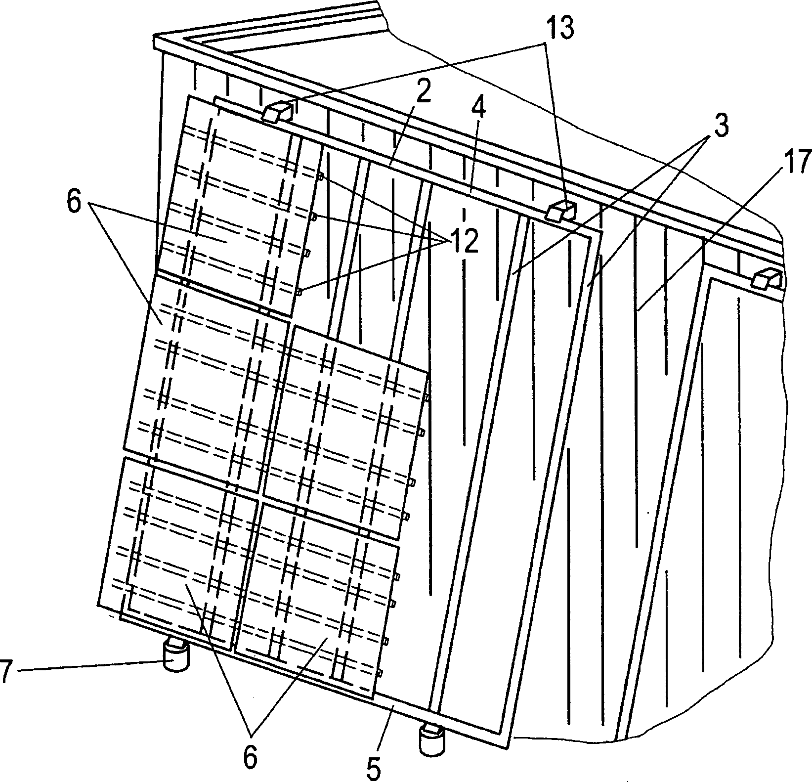
Ein Montagesystem (1) für Solarmodule (6) umfasst ein Bodenteil (11), an dem ein Gestell (2) abgestützt ist, auf dem ein oder mehrere plattenförmige Solarmodule (6) gehalten sind, und einen Anker (13, 35), der an einer Wand (17) eines Gebäudes festlegbar ist und das Gestell (2) in einem oberen Bereich abstützt, wobei das Bodenteil (11) um eine horizontale Achse (10) drehbar gelagert ist. Ferner betrifft die Erfindung ein Verfahren zur Montage einer Solaranlage.A mounting system (1) for solar modules (6) comprises a bottom part (11) on which a frame (2) is supported, on which one or more plate-shaped solar modules (6) are held, and an armature (13, 35) on a wall (17) of a building can be fixed and the frame (2) is supported in an upper region, wherein the bottom part (11) is rotatably mounted about a horizontal axis (10). Furthermore, the invention relates to a method for mounting a solar system.
Description
Die vorliegende Erfindung betrifft ein Montagesystem für Solarmodule, mit einer Unterkonstruktion, an der ein Gestell abgestützt ist, auf den ein oder mehrere plattenförmige Solarmodule gehalten sind, und einem Anker, der an einem Bauwerk festlegbar ist und das Gestell in einem oberen Bereich abstützt, sowie ein Verfahren zur Montage einer Solaranlage.The present invention relates to a mounting system for solar modules, with a substructure on which a frame is supported, on which one or more plate-shaped solar modules are held, and an anchor which can be fixed to a building and the frame is supported in an upper region, and a method for mounting a solar system.
Es sind Montagesysteme für Solarmodule bekannt, bei denen ein Gestell auf einer Unterkonstruktion, z. B. Rammpfosten, abgestützt ist. Das Gestell wird dabei in einem vorbestimmten Neigungswinkel entweder auf mehreren die Unterkonstruktion bildenden Pfosten montiert, wobei vordere kurze Pfosten zur Südseite und hintere längere Pfosten zur Nordseite angeordnet sind, oder auf nur einem Pfosten, wobei das Gestell in etwa im Mittelpunkt getragen wird, so dass eine gleichmäßige Lastabtragung gegeben ist. Diese Montagesysteme können auf oder an Gebäuden angeordnet sein oder auf Freilandflächen. Nachteilig ist, dass neben dem Gestell relativ aufwendige und teuere Unterkonstruktionen bereitgestellt werden müssen. Insbesondere bei sehr großen Solaranlagen ist die Montage schwierig und aufwendig.There are mounting systems for solar modules are known in which a frame on a substructure, for. B. Rammpfosten supported. The frame is thereby mounted at a predetermined angle of inclination either on a plurality of posts forming the substructure, with front short posts to the south side and rear longer posts to the north side, or on one post only, with the frame being carried at about the center, so that a uniform load transfer is given. These mounting systems can be arranged on or on buildings or outdoor areas. The disadvantage is that in addition to the frame relatively expensive and expensive substructures must be provided. Especially with very large solar systems, the installation is difficult and expensive.
Des Weiteren sind fassadenintegrierte Montagesysteme für Solarmodule bekannt, die einen Teil der Gebäudehülle bilden. Hierbei haben die Systeme neben den reinen Haltefunktionen auch noch weitere Aufgaben zu erfüllen, wie z. B. Wärmeisolation und/oder das Bereitstellen einer dichten Fassade bzw. eines dichten Fassadenabschnittes. Nachteilig ist hierbei, dass eine Nachrüstung an der Gebäudehülle nicht möglich ist bzw. nur mit erheblichem Aufwand betrieben werden kann.Furthermore, façade-integrated mounting systems for solar modules are known, which form part of the building envelope. Here, the systems in addition to the pure holding functions also have to fulfill other tasks, such. B. thermal insulation and / or providing a dense facade or a dense facade section. The disadvantage here is that retrofitting to the building envelope is not possible or can be operated only with considerable effort.
Es ist daher Aufgabe der vorliegenden Erfindung, ein Montagesystem für Solarmodule sowie ein Verfahren zur Montage einer Solaranlage zu schaffen, die flexibel an die örtlichen Gegebenheiten angepasst werden können und eine einfache Montage ermöglichen. Zudem soll das Montagesystem auch zur Nachrüstung an Gebäuden geeignet sein.It is therefore an object of the present invention to provide a mounting system for solar modules and a method for mounting a solar system, which can be flexibly adapted to local conditions and allow easy installation. In addition, the mounting system should also be suitable for retrofitting to buildings.
Zur Lösung dieser Aufgabe wird ein Montagesystem mit den Merkmalen des Anspruches 1 sowie ein Verfahren zur Montage einer Solaranlage mit den Merkmalen des Anspruches 7 bereitgestellt.To solve this problem, a mounting system with the features of
Erfindungsgemäß ist bei dem Montagesystem das Bodenteil um eine horizontale Achse drehbar gelagert und das Gestell ist in unterschiedlichen Neigungswinkeln fixierbar. Dadurch kann auf einfache Weise eine Vormontage der Solaranlage am Boden erfolgen, um dann das Bodenteil zusammen mit dem Gestell und den Solarmodulen aufzurichten und an einem Bauwerk oder anderen Element festzulegen. Dadurch können auch große Flächen effektiv montiert werden. Zudem ist es möglich, durch die verschwenkbare Lagerung eine Neigungsverstellung vorzunehmen, beispielsweise um die Solarmodule je nach Jahreszeit optimiert auszurichten. In den Wintermonaten steht die Sonne weniger hoch, so dass eine steilere Ausrichtung der Solarmodule vorteilhaft ist. Während der Sommermonate hingegen kann eine flachere Ausrichtung der Solarmodule den Wirkungsgrad erhöhen. Die Neigungsverstellung kann auch nach der ersten Montage erfolgen.According to the invention, the base part is rotatably mounted about a horizontal axis in the mounting system and the frame can be fixed in different angles of inclination. This can be done in a simple manner, a pre-assembly of the solar system on the ground, then erect the bottom part together with the frame and the solar modules and set to a building or other element. As a result, even large areas can be effectively mounted. In addition, it is possible to make a tilt adjustment through the pivotable storage, for example, to align the solar modules optimally depending on the season. In the winter months, the sun is less high, so that a steeper orientation of the solar modules is advantageous. During the summer months, however, a flatter orientation of the solar modules can increase the efficiency. The tilt adjustment can also be done after the first assembly.
In einer vorteilhaften Ausgestaltung werden die auftretenden Gewichtslasten durch die Unterkonstruktion abgetragen, während Kräfte durch Windlasten von dem Anker aufgenommen werden. Dadurch treten an den Befestigungselementen im Wesentlichen nur Zug- und Druckkräfte auf.In an advantageous embodiment, the occurring weight loads are removed by the substructure, while forces are absorbed by wind loads from the anchor. As a result, essentially only tensile and compressive forces occur on the fastening elements.
Vorzugsweise ist das Bodenteil an einem feststehendem Teil gelagert, das an einem Sockel oder Pfosten bodenseitig festgelegt ist. Dadurch kann je nach Untergrund eine stabile Befestigung des Halteteils erfolgen, an dem das Bodenteil verschwenkbar gelagert ist. Das feststehende Teil und das Bodenteil können über ein Scharniergelenk miteinander verbunden sein, das je nach den auftretenden Gewichtslasten entsprechend stabil dimensioniert sein kann.Preferably, the bottom part is mounted on a fixed part, which is fixed to the bottom side on a pedestal or post. As a result, depending on the substrate, a stable attachment of the holding part takes place, on which the bottom part is pivotably mounted. The fixed part and the bottom part can be connected to each other via a hinge joint, which can be dimensioned according to stable depending on the weight loads occurring.
Gemäß einer weiteren Ausgestaltung der Erfindung ist die Neigung des Gestells über die Anker verstellbar. Hierfür können die Anker längenverstellbar ausgebildet sein, um den Neigungswinkel des Gestells durch Verschwenken um die horizontale Achse an dem Bodenteil zu justieren.According to a further embodiment of the invention, the inclination of the frame via the anchor is adjustable. For this purpose, the anchor can be made adjustable in length to adjust the inclination angle of the frame by pivoting about the horizontal axis of the bottom part.
Für eine einfache Montage sind zudem die Pfosten in Längsrichtung vorzugsweise verschiebbar an einem mit dem Anker verbundenen Halteteil gelagert. Das Halteteil kann dann endseitig auf den Pfosten aufgeschoben werden, um in der gewünschten Höhe fixiert zu werden. Dadurch können Wärmespannungen vermieden werden. Gerade wenn die Pfosten in größerer Länge eingesetzt werden, beispielsweise über 5 m, ist ein entsprechender Toleranzausgleich durch Verschieben der Pfosten relativ zu dem Halteteil vorteilhaft.For a simple assembly, moreover, the uprights are preferably mounted so as to be displaceable on a holding part connected to the armature. The holding part can then be pushed on the end of the post to be fixed at the desired height. As a result, thermal stresses can be avoided. Just when the posts are used in greater length, for example, over 5 m, a corresponding tolerance compensation by moving the post relative to the holding part is advantageous.
Erfindungsgemäß wird auch ein Verfahren zur Montage einer Solaranlage mit den folgenden Schritten bereitgestellt:
- – Fixieren eines Profils an einem bodenseitig festgelegten Bodenteil;
- – Aufrichten des Profils durch Verschwenken um eine horizontale Achse, und
- – Festlegen eines Halteteils im oberen Bereich des Profils und Fixieren des Halteteils durch einen Anker an einem Bauwerk.
- - Fixing a profile on a bottom side fixed bottom part;
- - Erecting the profile by pivoting about a horizontal axis, and
- - Setting a holding part in the upper part of the profile and fixing the holding part by an anchor to a building.
Durch das erfindungsgemäße Montageverfahren können standardisierte Verfahrensschritte eingesetzt werden, um eine Solaranlage effektiv zu montieren, so dass sich in kurzer Zeit auch große Flächen befestigen lassen. Insbesondere kann durch die verschwenkbare Lagerung des Gestells auch eine entsprechende Ausrichtung und flexible Anpassung an unterschiedliche Gegebenheiten durch Bodenbeschaffenheit und/oder Gebäudegeometrien vorgenommen werden. Auch eine nachträgliche Montage einer Solaranlage an einem bestehendem Bauwerk, wie der Wand oder Fassade eines Gebäudes ist problemlos möglich. By means of the assembly method according to the invention, standardized method steps can be used to effectively mount a solar system, so that even large areas can be fastened in a short time. In particular, by the pivotable mounting of the frame and a corresponding alignment and flexible adaptation to different conditions by soil conditions and / or building geometries can be made. Also, a subsequent installation of a solar system to an existing structure, such as the wall or facade of a building is easily possible.
Vorzugsweise werden mehrere Profile über Querstreben zur Bildung eines Gestells miteinander verbunden, bevor die Profile aufgerichtet werden. Dadurch kann am Boden eine Montage des mit Solarmodulen zu belegenden Gestells vorgenommen werden, das dann als Einheit aufgerichtet wird, was eine Montage in großen Höhen vermeidet. Dabei kann das Gestell in einem Zwischenschritt beabstandet vom Boden positioniert werden, um die Solarmodule mechanisch zu fixieren und miteinander zu verkabeln. Dann kann das Gestell auch mit montierten Solarmodulen aufgerichtet werden, so dass bodenseitig eine vollständige Montage des Gestells mit den darauf angeordneten Solarmodulen erfolgt, die dann als Einheit aufgerichtet werden und dann lediglich in der gewünschten Position an einem Gebäude oder anderen Bauwerk festgelegt werden.Preferably, several profiles are connected to each other via cross struts to form a frame before the profiles are erected. As a result, can be made on the ground mounting the solar modules to be occupied frame, which is then erected as a unit, which avoids mounting at high altitudes. In this case, the frame can be positioned at a distance from the ground in an intermediate step in order to fix the solar modules mechanically and to wire them together. Then, the frame can also be erected with mounted solar modules, so that the bottom is a complete assembly of the frame with the solar modules arranged thereon, which are then erected as a unit and then set only in the desired position on a building or other structure.
Die Erfindung wird nachfolgend anhand mehrerer Ausführungsbeispiele mit Bezug auf die beigefügten Zeichnungen näher erläutert. Es zeigen:The invention will be explained in more detail with reference to several embodiments with reference to the accompanying drawings. Show it:
Ein Montagesystem
Das Gestell
Im oberen Bereich ist das Gestell
In den
In
Ferner umfasst das Bodenteil
Wie in
In den
In
Am Boden
In den
Die Fixierung der Hülsen
Zudem kann zwischen der Hülse
In den
Anschließend werden die Pfosten
In
In
In
In den dargestellten Ausführungsbeispielen werden die Halteteile
Claims (10)
Priority Applications (3)
| Application Number | Priority Date | Filing Date | Title |
|---|---|---|---|
| DE102010016529A DE102010016529A1 (en) | 2010-04-19 | 2010-04-19 | Mounting system for solar modules and method for mounting a solar system |
| EP11162348A EP2378221A2 (en) | 2010-04-19 | 2011-04-14 | Mounting system for solar modules and method for mounting a solar assembly |
| US13/089,564 US20110266234A1 (en) | 2010-04-19 | 2011-04-19 | Mounting system for solar modules and method for installing a solar system |
Applications Claiming Priority (1)
| Application Number | Priority Date | Filing Date | Title |
|---|---|---|---|
| DE102010016529A DE102010016529A1 (en) | 2010-04-19 | 2010-04-19 | Mounting system for solar modules and method for mounting a solar system |
Publications (1)
| Publication Number | Publication Date |
|---|---|
| DE102010016529A1 true DE102010016529A1 (en) | 2011-10-20 |
Family
ID=44064725
Family Applications (1)
| Application Number | Title | Priority Date | Filing Date |
|---|---|---|---|
| DE102010016529A Withdrawn DE102010016529A1 (en) | 2010-04-19 | 2010-04-19 | Mounting system for solar modules and method for mounting a solar system |
Country Status (3)
| Country | Link |
|---|---|
| US (1) | US20110266234A1 (en) |
| EP (1) | EP2378221A2 (en) |
| DE (1) | DE102010016529A1 (en) |
Families Citing this family (7)
| Publication number | Priority date | Publication date | Assignee | Title |
|---|---|---|---|---|
| US20110197418A1 (en) * | 2010-02-16 | 2011-08-18 | Michael Charles Overturf | String Solar Panel Mounting System |
| US9216692B2 (en) * | 2010-02-17 | 2015-12-22 | GM Global Technology Operations LLC | Seat panel pocket and method |
| ITVI20120204A1 (en) * | 2012-08-07 | 2014-02-08 | Giovanni Bianchini | FIXING ELEMENT FOR SOLAR ENERGY SYSTEMS AND SYSTEM INCLUDING THIS ELEMENT. |
| US9416992B2 (en) * | 2014-02-28 | 2016-08-16 | Sunpower Corporation | End clamps for solar systems |
| FR3112912B1 (en) * | 2020-07-27 | 2022-08-12 | Beem Energy | PHOTOVOLTAIC PANEL AND FASTENING DEVICE FOR SUCH PANEL |
| EP4431835A1 (en) * | 2023-03-16 | 2024-09-18 | Zendra Ag | Assembly with at least one, in particular plate-shaped, photovoltaic module |
| NO20240097A1 (en) * | 2024-02-02 | 2025-08-04 | Thomas Laiq | A system for mounting solar panels |
Citations (2)
| Publication number | Priority date | Publication date | Assignee | Title |
|---|---|---|---|---|
| WO2001007845A1 (en) * | 1999-07-27 | 2001-02-01 | Glaswerke Arnold Gmbh & Co. Kg | Transparent thermal insulation device |
| GB2365518A (en) * | 2000-06-07 | 2002-02-20 | Nissim Leon Jacob | Mounting for a solar collector |
Family Cites Families (28)
| Publication number | Priority date | Publication date | Assignee | Title |
|---|---|---|---|---|
| US4371139A (en) * | 1979-12-31 | 1983-02-01 | Sunsearch, Inc. | Adjustable mounting rack for solar collectors |
| BR9007327A (en) * | 1989-04-25 | 1992-04-28 | Glasstech Inc | SUPPORT SET FOR ASSEMBLY OF A PANEL SET |
| US5228924A (en) * | 1991-11-04 | 1993-07-20 | Mobil Solar Energy Corporation | Photovoltaic panel support assembly |
| US6046399A (en) * | 1997-01-13 | 2000-04-04 | Kapner; Mark | Roofing panels with integral brackets for accepting inclined solar panels |
| US6111189A (en) * | 1998-07-28 | 2000-08-29 | Bp Solarex | Photovoltaic module framing system with integral electrical raceways |
| DE19934073B4 (en) * | 1999-07-19 | 2005-08-25 | Regen Energiesysteme Gmbh | Device for fixing solar modules |
| US6360491B1 (en) * | 2000-01-14 | 2002-03-26 | Stanley A. Ullman | Roof support system for a solar panel |
| JP2002141541A (en) * | 2000-10-31 | 2002-05-17 | Canon Inc | Solar power generation equipment and buildings |
| EP1341240B1 (en) * | 2000-11-16 | 2016-11-02 | Kaneka Corporation | Solar battery module, photovoltaic power generation system, support block supporting solar battery module |
| US6534703B2 (en) * | 2001-07-10 | 2003-03-18 | Powerlight Corporation | Multi-position photovoltaic assembly |
| US7434362B2 (en) * | 2001-07-20 | 2008-10-14 | Unirac, Inc. | System for removably and adjustably mounting a device on a surface |
| US6722357B2 (en) * | 2001-08-15 | 2004-04-20 | Powerlight Corporation | Fixed angle solar collector arrangement |
| US20030154667A1 (en) * | 2002-02-20 | 2003-08-21 | Dinwoodie Thomas L. | Shingle system |
| US7435897B2 (en) * | 2002-04-11 | 2008-10-14 | Schott Solar, Inc. | Apparatus and method for mounting photovoltaic power generating systems on buildings |
| US7574842B2 (en) * | 2002-04-11 | 2009-08-18 | Schott Solar, Inc. | Apparatus for mounting photovoltaic power generating systems on buildings |
| US7600349B2 (en) * | 2003-02-26 | 2009-10-13 | Unirac, Inc. | Low profile mounting system |
| US6959517B2 (en) * | 2003-05-09 | 2005-11-01 | First Solar, Llc | Photovoltaic panel mounting bracket |
| US7513250B2 (en) * | 2004-01-23 | 2009-04-07 | Ray Head | Positioning system for portable solar panels |
| US7592537B1 (en) * | 2004-02-05 | 2009-09-22 | John Raymond West | Method and apparatus for mounting photovoltaic modules |
| US7856769B2 (en) * | 2004-02-13 | 2010-12-28 | Pvt Solar, Inc. | Rack assembly for mounting solar modules |
| US7297866B2 (en) * | 2004-03-15 | 2007-11-20 | Sunpower Corporation | Ventilated photovoltaic module frame |
| US7406800B2 (en) * | 2004-05-18 | 2008-08-05 | Andalay Solar, Inc. | Mounting system for a solar panel |
| AU2005320353B2 (en) * | 2005-01-10 | 2008-10-02 | Mounting Systems Gmbh | Threaded slider mounting system |
| US7814899B1 (en) * | 2006-07-04 | 2010-10-19 | Jonathan Port | Solar panel mounting systems |
| US7921843B1 (en) * | 2007-02-06 | 2011-04-12 | Rawlings Lyle K | System and method for anchoring solar panels to a flat surface |
| US8813460B2 (en) * | 2007-09-21 | 2014-08-26 | Andalay Solar, Inc. | Mounting system for solar panels |
| US8061091B2 (en) * | 2008-06-27 | 2011-11-22 | Sunpower Corporation | Photovoltaic module kit including connector assembly for non-penetrating array installation |
| US8065844B2 (en) * | 2008-06-27 | 2011-11-29 | Sunpower Corporation | Ballasted photovoltaic module and module arrays |
-
2010
- 2010-04-19 DE DE102010016529A patent/DE102010016529A1/en not_active Withdrawn
-
2011
- 2011-04-14 EP EP11162348A patent/EP2378221A2/en not_active Withdrawn
- 2011-04-19 US US13/089,564 patent/US20110266234A1/en not_active Abandoned
Patent Citations (3)
| Publication number | Priority date | Publication date | Assignee | Title |
|---|---|---|---|---|
| WO2001007845A1 (en) * | 1999-07-27 | 2001-02-01 | Glaswerke Arnold Gmbh & Co. Kg | Transparent thermal insulation device |
| US6758211B1 (en) * | 1999-07-27 | 2004-07-06 | Glaswerke Arnold Gmbh & Co. Kg | Transparent thermal insulation device |
| GB2365518A (en) * | 2000-06-07 | 2002-02-20 | Nissim Leon Jacob | Mounting for a solar collector |
Also Published As
| Publication number | Publication date |
|---|---|
| US20110266234A1 (en) | 2011-11-03 |
| EP2378221A2 (en) | 2011-10-19 |
Similar Documents
| Publication | Publication Date | Title |
|---|---|---|
| EP2669451A2 (en) | Support structure and method for assembling a support structure | |
| WO2006072230A1 (en) | Threaded slider mounting system | |
| DE102010016529A1 (en) | Mounting system for solar modules and method for mounting a solar system | |
| WO2020049374A1 (en) | Adjustment fitting and support system for solar panels | |
| DE9109605U1 (en) | Kit of a mounting frame for roof mounting of solar modules | |
| DE202011050810U1 (en) | Support element for a substructure for a solar module | |
| EP3978825B1 (en) | Device for supporting solar modules, kit, manufacturing method and solar module assembly | |
| DE202010005250U1 (en) | Mounting system for solar modules | |
| EP3781762B1 (en) | Device and method for constructing a swimming pool | |
| DE102005032859B3 (en) | Fixing system for solar modules has bent U-shaped holder with arm fixed to mounting rail and sprung bowed piece that can be bolted to press module against the rail | |
| DE69919987T2 (en) | TENSIONER WITH MULTIPLE TIPS | |
| WO2022017656A1 (en) | Supporting structure for supporting solar modules and ceiling elements | |
| DE202010010140U1 (en) | Perfected swiveling support for solar panels | |
| WO2016156382A1 (en) | Mounting system and mounting method | |
| AT523944B1 (en) | railing module | |
| EP3978827B1 (en) | Device for supporting solar modules, kit, manufacturing method and solar module assembly | |
| DE202014100961U1 (en) | Solar Panel System | |
| WO2014029501A2 (en) | Pv generator having a drainage via the eaves | |
| DE102011104455B4 (en) | Assembly of a stand for PV modules, holding attachment and method for assembling the assembly | |
| DE10152067A1 (en) | Antenna mast fixing device for securing to roof truss, has base with holes for fixing to roof spars, and allows adjustment of the mast positioning | |
| DE102018203080B4 (en) | FOUNDATION SYSTEM FOR THE STORAGE OF SOLAR PANELS ARRANGED ALONGSIDE | |
| EP2378564A2 (en) | Mounting system for solar modules | |
| DE202010005576U1 (en) | wall construction | |
| DE102023005386B4 (en) | Kit for mounting solar modules | |
| EP3786385B1 (en) | Fork element for use in a fastening structure with reduced number of components |
Legal Events
| Date | Code | Title | Description |
|---|---|---|---|
| R012 | Request for examination validly filed | ||
| R016 | Response to examination communication | ||
| R119 | Application deemed withdrawn, or ip right lapsed, due to non-payment of renewal fee |
Effective date: 20131101 |