DE102010007856A1 - Method and disconnect bar for alternatively connecting an output line connected to a first input line to a second input line - Google Patents
Method and disconnect bar for alternatively connecting an output line connected to a first input line to a second input line Download PDFInfo
- Publication number
- DE102010007856A1 DE102010007856A1 DE102010007856A DE102010007856A DE102010007856A1 DE 102010007856 A1 DE102010007856 A1 DE 102010007856A1 DE 102010007856 A DE102010007856 A DE 102010007856A DE 102010007856 A DE102010007856 A DE 102010007856A DE 102010007856 A1 DE102010007856 A1 DE 102010007856A1
- Authority
- DE
- Germany
- Prior art keywords
- contact
- plug
- input line
- isolating
- wire
- Prior art date
- Legal status (The legal status is an assumption and is not a legal conclusion. Google has not performed a legal analysis and makes no representation as to the accuracy of the status listed.)
- Withdrawn
Links
- 238000000034 method Methods 0.000 title claims abstract description 8
- 238000000926 separation method Methods 0.000 claims description 2
- 238000003780 insertion Methods 0.000 claims 1
- 230000037431 insertion Effects 0.000 claims 1
- 238000006073 displacement reaction Methods 0.000 description 3
- 238000009413 insulation Methods 0.000 description 3
- 239000004020 conductor Substances 0.000 description 2
- 238000010586 diagram Methods 0.000 description 2
- 230000009977 dual effect Effects 0.000 description 2
- 239000012212 insulator Substances 0.000 description 2
- 230000001419 dependent effect Effects 0.000 description 1
- 230000000694 effects Effects 0.000 description 1
- 230000008707 rearrangement Effects 0.000 description 1
- 210000002023 somite Anatomy 0.000 description 1
- 238000010618 wire wrap Methods 0.000 description 1
Images


Classifications
-
- H—ELECTRICITY
- H04—ELECTRIC COMMUNICATION TECHNIQUE
- H04Q—SELECTING
- H04Q1/00—Details of selecting apparatus or arrangements
- H04Q1/02—Constructional details
- H04Q1/14—Distribution frames
- H04Q1/142—Terminal blocks for distribution frames
-
- Y—GENERAL TAGGING OF NEW TECHNOLOGICAL DEVELOPMENTS; GENERAL TAGGING OF CROSS-SECTIONAL TECHNOLOGIES SPANNING OVER SEVERAL SECTIONS OF THE IPC; TECHNICAL SUBJECTS COVERED BY FORMER USPC CROSS-REFERENCE ART COLLECTIONS [XRACs] AND DIGESTS
- Y10—TECHNICAL SUBJECTS COVERED BY FORMER USPC
- Y10T—TECHNICAL SUBJECTS COVERED BY FORMER US CLASSIFICATION
- Y10T29/00—Metal working
- Y10T29/49—Method of mechanical manufacture
- Y10T29/49826—Assembling or joining
- Y10T29/49947—Assembling or joining by applying separate fastener
Landscapes
- Engineering & Computer Science (AREA)
- Computer Networks & Wireless Communication (AREA)
- Details Of Connecting Devices For Male And Female Coupling (AREA)
Abstract
Die Erfindung betrifft ein Verfahren zum alternativen Verbinden einer mit einer ersten Eingangsleitung (50) verbundenen Ausgangsleitung (51) mit einer zweiten Eingangsleitung (52), mittels mindestens einer Trennleiste (10), wobei die Trennleiste (10) erste Kontaktelemente (20) mit einem ersten Aderanschlusskontakt (21) und einem ersten Kontaktschenkel (22) und zweite Kontaktelemente (30) mit einem zweiten Aderanschlusskontakt (31) und einem zweiten Kontaktschenkel (32) umfasst, wobei jeweils ein erster und ein zweiter Kontaktschenkel (22, 32) einen Trennkontakt (40) bilden, wobei an die ersten Aderanschlusskontakte (21) die ersten Eingangsleitungen (50) angeschlossen sind und an die zweiten Aderanschlusskontakte (31) die Ausgangsleitungen (51) angeschlossen sind, wobei mittels eines Trennsteckers (70, 70a) der Trennkontakt (40) geöffnet wird und damit die Verbindung zwischen erster Eingangsleitung (50) und Ausgangsleitung (51) aufgetrennt wird, wobei die zweite Eingangsleitung (52) über den Trennstecker (70, 70a) und den zweiten Kontaktschenkel (32) oder über einen dritten Aderanschlusskontakt (33) am zweiten Kontaktelement (30) mit der Ausgangsleitung (51) verbunden wird, sowie eine Trennleiste (10).The invention relates to a method for alternately connecting an output line (51) connected to a first input line (50) to a second input line (52) by means of at least one separator strip (10), wherein the separator strip (10) comprises first contact elements (20) with a first core terminal contact (21) and a first contact leg (22) and second contact elements (30) with a second wire terminal contact (31) and a second contact leg (32), wherein in each case a first and a second contact legs (22, 32) a break contact ( 40), the first input leads (50) being connected to the first core connection contacts (21) and the output leads (51) being connected to the second core connection contacts (31), the disconnect contact (40) being provided by means of a disconnect plug (70, 70a). is opened and thus the connection between the first input line (50) and output line (51) is separated, wherein the second input line (52) ü is connected to the output line (51) via the isolating plug (70, 70a) and the second contact leg (32) or via a third wire terminal contact (33) on the second contact element (30), and a disconnect strip (10).
Description
Die Erfindung betrifft ein Verfahren und eine Trennleiste zum alternativen Verbinden einer mit einer ersten Eingangsleitung verbundenen Ausgangsleitung mit einer zweiten Eingangsleitung.The invention relates to a method and a disconnect strip for alternatively connecting an output line connected to a first input line to a second input line.
Möchte ein Teilnehmer seinen Provider wechseln, beispielsweise um XDSL-Dienste zu nutzen, so stellt sich das Problem, dass eine Umrangierung vorgenommen werden muss. Dies erfolgte zunächst im Bereich der Hauptverteiler, wo die Umrangierung in so genannten Kollokationsverteilern erfolgte. Zukünftig soll die Umrangierung im Bereich der Kabelverzweiger erfolgen. Hierzu führt der Netzbetreiber wie bisher ein Hauptkabel vom Hauptverteiler zum Kabelverzweiger, wo diese in Form von Doppeladern angeschlossen werden. Auf der Strecke vom Hauptverteiler zum Kabelverzweiger werden die Doppeladern, in einen neu aufzubauenden Kollokationsverteiler, auf zwei getrennte Endverschlüsse (ankommend und abgehend) abgeschlossen. Im Normalbetrieb sind beide Endverschlüsse 1 zu 1 durchrangiert.If a subscriber wants to change his provider, for example, to use XDSL services, then the problem arises that a rearrangement must be made. This initially took place in the area of the main distributors, where the relocation took place in so-called collocation distributors. In future, the relocation will take place in the area of cable distributors. For this purpose, the network operator continues as before a main cable from the main distributor to the cable distributor, where they are connected in the form of double cores. On the route from the main distributor to the cable distributor, the double cores, in a new collocation distributor to be set up, are terminated on two separate terminations (incoming and outgoing). In normal operation, both end closures are 1 to 1 durchraniert.
Ein alternativer Service-Provider kann dann neben dem Kollokationsverteiler des Netzbetreibers einen weiteren Kabelverzweiger/Multifunktionsgehäuse aufbauen. Zwischen beiden Verteilern werden Doppeladern auf Endverschlüsse abgelegt. Will dann ein Teilnehmer vom Netzbetreiber zum alternativen Service-Provider wechseln, so wird eine Doppelader des alternativen Service-Providers von seinem Endverschluss im Kollokationsverteiler zum Endverschluss (abgehend) des Netzbetreibers rangiert. Mit dieser Rangierung muss die Verbindung der Endverschlüsse (ankommend u. abgehend) des Netzbetreibers aufgehoben werden und der alte Rangierdraht ist zu entfernen. Dies stellt einen nicht unerheblichen Rangieraufwand dar, wobei zusätzlich durch nicht vollständige Entfernung der ursprünglichen Rangierdrähte der Kollokationsverteiler mit Adern ”zuwächst”.An alternative service provider can then set up another cable splitter / multifunction housing in addition to the collocation distributor of the network operator. Between the two distributors, double cores are placed on terminations. If a subscriber then wants to change from the network operator to the alternative service provider, then a double wire of the alternative service provider is ranged from its end closure in the collocation distributor to the end closure (outgoing) of the network operator. With this routing, the connection of the terminations (incoming and outgoing) of the network operator must be canceled and the old jumper wire must be removed. This represents a not insignificant maneuvering effort, whereby in addition by incomplete removal of the original jumper wires, the collocation distributor with wires "grows".
Der Erfindung liegt das technische Problem zugrunde, ein Verfahren und eine Trennleiste zum alternativen Verbinden einer mit einer ersten Eingangsleitung verbundenen Ausgangsleitung mit einer zweiten Eingangsleitung zu schaffen, mittels derer der notwendige Rangieraufwand reduziert wird.The invention is based on the technical problem of providing a method and a disconnect strip for alternatively connecting an output line connected to a first input line to a second input line, by means of which the necessary maneuvering effort is reduced.
Die Lösung des technischen Problems ergibt sich durch die Gegenstände mit den Merkmalen der Ansprüche 1, 4 und 8. Weitere vorteilhafte Ausgestaltungen der Erfindung ergeben sich aus den Unteransprüchen.The solution of the technical problem results from the objects with the features of claims 1, 4 and 8. Further advantageous embodiments of the invention will become apparent from the dependent claims.
Das Verfahren zum alternativen Verbinden mindestens einer mit einer ersten Eingangsleitung verbundenen Ausgangsleitung mit einer zweiten Eingangsleitung, mittels mindestens einer Trennleiste, wobei die Trennleiste erste Kontaktelemente mit einem ersten Aderanschlusskontakt und einem ersten Kontaktschenkel und zweite Kontaktelemente mit einem zweiten Aderanschlusskontakt und einem zweiten Kontaktschenkel umfasst, wobei jeweils ein erster und ein zweiter Kontaktschenkel einen Trennkontakt bilden, wobei an die ersten Aderanschlusskontakte die ersten Eingangsleitungen angeschlossen sind und an die zweiten Aderanschlusskontakte die Ausgangsleitungen angeschlossen sind, umfasst folgende Verfahrensschritte: Mittels eines Trennsteckers wird der Trennkontakt geöffnet und damit die Verbindung zwischen erster Eingangsleitung und Ausgangsleitung aufgetrennt, wobei die zweite Eingangsleitung über den Trennstecker und den zweiten Kontaktschenkel oder über einen dritten Aderanschlusskontakt am zweiten Kontaktelement mit der Ausgangsleitung verbunden wird. Somit kann der Rangiervorgang in einem Verteiler erfolgen und der separate Kollokationsverteiler entfallen. Hierdurch entfallen auch die notwendigen Umrangierungen zwischen den Verteilern.The method for alternately connecting at least one output line connected to a first input line to a second input line, by means of at least one disconnect strip, the disconnect strip comprising first contact elements with a first wire terminal contact and a first contact leg and second contact elements with a second wire terminal contact and a second contact leg in each case a first and a second contact leg form a separating contact, wherein the first input leads are connected to the first wire connection contacts and the output wires are connected to the second wire terminal contacts, comprising the following steps: By means of a disconnect plug, the isolating contact is opened and thus the connection between the first input line and Separated output line, wherein the second input line via the isolating plug and the second contact legs or via a third wire terminal contact on the two Iten contact element is connected to the output line. Thus, the maneuvering can be done in a distributor and the separate collocation distributor omitted. This also eliminates the need to rearrange between the distributors.
In der einen Alternativen erfolgt der Anschluss der zweiten Eingangsleitung durch den Trennstecker. Dabei ist der Trennstecker beispielsweise am Ende der Eingangsleitung angeordnet, wobei vorzugsweise durch einen Trennstecker jeweils eine Doppelader angeschaltet wird, d. h. der Trennstecker öffnet gleichzeitig zwei Trennkontakte. Hierzu weist der Trennstecker Kontaktflächen auf, mit denen die zweiten Eingangsleitungen verbunden sind, wobei beim Einstecken in den bzw. die Trennkontakte die Kontaktflächen mit den zweiten Kontaktschenkeln eine elektrische Verbindung herstellen. Alternativ kann der Trennstecker an der Oberseite mit Aderanschlusskontakten ausgebildet sein, die dann mit den Kontaktflächen elektrisch verbunden sind, wobei die zweiten Eingangsleitungen an die Aderanschlusskontakte angeschlossen werden.In one alternative, the second input line is connected through the isolating plug. In this case, the isolating plug is arranged, for example, at the end of the input line, wherein in each case a double wire is preferably connected by a separating plug, d. H. The isolating plug simultaneously opens two isolating contacts. For this purpose, the isolating plug on contact surfaces with which the second input lines are connected, wherein when inserted into the or the isolating contacts, the contact surfaces with the second contact legs establish an electrical connection. Alternatively, the isolating plug may be formed on the upper side with wire connection contacts, which are then electrically connected to the contact surfaces, wherein the second input lines are connected to the wire connection contacts.
In der zweiten Alternative ist das zweite Kontaktelement mit einem dritten Aderanschlusskontakt ausgebildet, der mit dem zweiten Aderanschlusskontakt elektrisch verbunden ist. In diesem Fall trennt der Trennstecker die ursprüngliche Verbindung nur auf, wohingegen die neue Verbindung durch Anschluss der zweiten Eingangsleitung an den dritten Aderanschlusskontakt erfolgt.In the second alternative, the second contact element is formed with a third wire terminal contact, which is electrically connected to the second wire terminal contact. In this case, the disconnect plug only disconnects the original connection, whereas the new connection is made by connecting the second input line to the third wire terminal contact.
In einer bevorzugten Ausführungsform wird durch Anschaltung der zweiten Eingangsleitung der Trennstecker in den Trennkontakt gedrückt. Dadurch wird sichergestellt, dass die erste Verbindung stets aufgetrennt ist, bevor die zweite Eingangsleitung angeschlossen wird. Dadurch wird verhindert, dass gleichzeitig zwei unterschiedliche Service-Provider auf die gleiche Ausgangsleitung geschaltet sind.In a preferred embodiment, the isolating plug is pressed into the isolating contact by connecting the second input line. This ensures that the first connection is always disconnected before the second input line is connected. This prevents two different service providers from being connected to the same output line at the same time.
In einer weiteren bevorzugten Ausführungsform wird der Trennstecker im eingesteckten Zustand verriegelt. Dadurch wird verhindert, dass der Trennstecker versehentlich gezogen werden kann. Vorzugsweise ist die Verriegelung derart ausgestaltet, dass ein Ziehen des Trennsteckers die Entfernung der zweiten Eingangsleitung voraussetzt oder bewirkt. In a further preferred embodiment, the isolating plug is locked in the inserted state. This prevents the disconnect plug from being accidentally pulled. Preferably, the latch is configured such that pulling the isolator plug presupposes or effects the removal of the second input line.
Die erfindungsgemäße Trennleiste umfasst erste Kontaktelemente mit jeweils einem ersten Aderanschlusskontakt und einem ersten Kontaktschenkel und zweite Kontaktelemente mit jeweils einem zweiten Aderanschlusskontakt und einem zweiten Kontaktschenkel, wobei jeweils ein erster und ein zweiter Kontaktschenkel einen Trennkontakt bilden, wobei die zweiten Kontaktelemente jeweils einen dritten Aderanschlusskontakt umfassen, der elektrisch mit dem zweiten Aderanschlusskontakt verbunden ist.The disconnect strip according to the invention comprises first contact elements, each having a first wire terminal contact and a first contact leg, and second contact elements each having a second wire terminal contact and a second contact leg, wherein each of a first and a second contact leg form a separation contact, wherein the second contact elements each comprise a third wire terminal contact, which is electrically connected to the second wire terminal contact.
Vorzugsweise ist die Trennleiste mit Rastmitteln ausgebildet, die mit Rastmitteln eines Trennsteckers diesen im eingesteckten Zustand im Trennkontakt verriegeln. Hierdurch wird ein versehentliches Ziehen des Trennsteckers vermieden.Preferably, the separating strip is formed with locking means which lock with locking means of a disconnect plug in the inserted state in the isolating contact. As a result, accidental pulling the separator plug is avoided.
Weiter vorzugsweise ist der Trennstecker bzw. sind die Trennstecker integrale Bestandteile der Trennleiste. Hierdurch ist der Trennstecker verliersicher angeordnet und es lässt sich eine äußerst flache Bauform mit eingesteckten Trennsteckern realisieren.Further preferably, the separating plug or the separating plug integral components of the separator strip. As a result, the separator plug is arranged captive and it can be an extremely flat design with inserted disconnect plugs realize.
In einer weiteren bevorzugten Ausführungsform sind die Trennstecker zu den dritten Aderanschlusskontakten derart positioniert, dass bei einer Beschaltung der dritten Aderanschlusskontakte die Trennstecker automatisch gesteckt werden.In a further preferred embodiment, the isolating plugs are positioned relative to the third wire connection contacts in such a way that when the third wire connection contacts are connected, the isolating plugs are inserted automatically.
Alternativ zum dritten Aderanschlusskontakt am zweiten Kontaktelement kann auch ein Trennstecker verwendet werden, umfassend einen Isolierkörper, wobei an der Oberseite des Trennsteckers Aderanschlusskontakte angeordnet sind, wobei an dem Isolierkörper Kontaktflächen angeordnet sind, die elektrisch mit den Aderanschlusskontakten verbunden sind.As an alternative to the third wire terminal contact on the second contact element, a separating plug can be used, comprising an insulating body, wherein at the top of the separator plug wire connection contacts are arranged, wherein on the insulating body contact surfaces are arranged, which are electrically connected to the wire connection contacts.
Die Erfindung wird nachfolgend anhand eines bevorzugten Ausführungsbeispiels näher erläutert. Die Fig. zeigen:The invention will be explained in more detail below with reference to a preferred embodiment. The figures show:
In der
In
An die ersten Aderanschlusskontakte
Soll nun anstelle der ersten Eingangsleitung
Soll nun wieder die Verbindung zur ersten Eingangsleitung
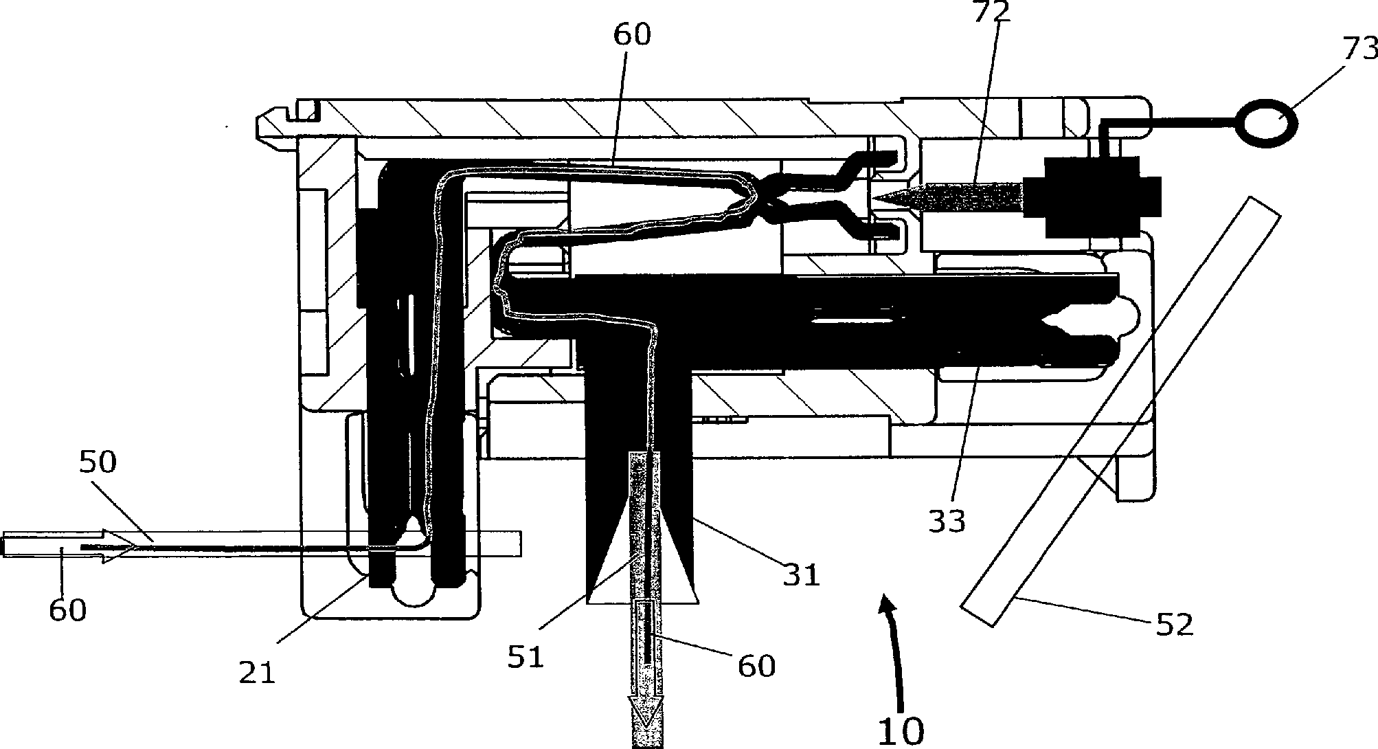
In der
- –
Die zweite Eingangsleitung 52 wird anden zugehörigen Aderanschlusskontakt 77 angeschaltet und anschließend wird der Trennstecker70a inden Trennkontakt 40 gesteckt oder - – der Trennstecker
70a wird inden Trennkontakt 40 gesteckt bzw. befindet sich in einer Position kurz vor dem gesteckten Zustand, wobei anschließend der oder die Eingangsleitungen52 an den oder dieAderanschlusskontakte 77 angeschaltet werden, wobei spätestens durch denAnschaltvorgang der Trennstecker 70a inden Trennkontakt 40 gesteckt wird. Über dieKontaktfläche 74 ist dann der Aderanschlusskontakt77 mit dem zweiten Kontaktschenkel32 und damit mit dem zweiten Aderanschlusskontakt31 elektrisch verbunden. Somit ist der zweite Signalweg61 hergestellt, wobei der erste Signalweg60 unterbrochen ist, da der Trennkontakt geöffnet ist und der Isolierkörper72 keine Signale vom ersten Kontaktschenkel22 überträgt.
- - The
second input line 52 is connected to the correspondingwire connection contact 77 turned on and then thedisconnect plug 70a in the isolatingcontact 40 plugged or - - the
disconnect plug 70a gets into the isolatingcontact 40 inserted or is in a position shortly before the inserted state, in which case the one ormore input lines 52 to the or thewire connection contacts 77 be turned on, at the latest by the connection of thedisconnect plug 70a in the isolatingcontact 40 is plugged. About thecontact surface 74 is then thewire connection contact 77 with thesecond contact leg 32 and thus with the secondwire connection contact 31 electrically connected. Thus, thesecond signal path 61 produced, wherein thefirst signal path 60 is interrupted because the isolating contact is open and theinsulator 72 no signals from thefirst contact leg 22 transfers.
BezugszeichenlisteLIST OF REFERENCE NUMBERS
- 1010
- Trennleiste (3 Aderanschlusskontakte)Isolating strip (3 wire connection contacts)
- 1111
- Trennleiste (2 Aderanschlusskontakte)Isolating strip (2 wire connection contacts)
- 2020
- erstes Kontaktelementfirst contact element
- 2121
- erster Aderanschlusskontaktfirst wire connection contact
- 2222
- erster Kontaktschenkelfirst contact leg
- 3030
- zweites Kontaktelementsecond contact element
- 3131
- zweiter Aderanschlusskontaktsecond wire connection contact
- 3232
- zweiter Kontaktschenkelsecond contact leg
- 3333
- zweiter Aderanschlusskontaktsecond wire connection contact
- 4040
- Trennkontaktisolating contact
- 4141
- GehäuseunterteilHousing bottom
- 4242
- GehäuseoberteilHousing top
- 4343
- Öffnungenopenings
- 4444
- Oberseite des GehäuseoberteilsTop of the housing top
- 5050
- erste Eingangsleitungfirst input line
- 5151
- Ausgangsleitungoutput line
- 5252
- zweite Eingangsleitungsecond input line
- 6060
- erster Signalwegfirst signal path
- 6161
- zweiter Signalwegsecond signal path
- 7070
- TrennsteckerDisconnect Terminal
- 70a70a
- TrennsteckerDisconnect Terminal
- 7171
- Gehäusecasing
- 7272
- Isolierkörperinsulator
- 7373
- Ziehhakenpull hook
- 7474
- Kontaktflächecontact area
- 7575
- Seite des IsolierkörpersSide of the insulating body
- 7676
- Oberseite des GehäusesTop of the housing
- 7777
- AderanschlusskontaktCable termination Contact
- 100100
- KabelverzweigerCabinet
- 110110
- KollokationsverteilerCollocation distributor
- 120120
- weiterer Verteileradditional distributor
- 130130
- Leitungencables
- 140140
- XDSL-LeitungXDSL line
- HKHK
- Hauptkabelmain cable
- RLRL
- Rangierleitungenjumpers
- TLTL
- Teilnehmerleitungensubscriber lines
Claims (8)
Priority Applications (2)
| Application Number | Priority Date | Filing Date | Title |
|---|---|---|---|
| DE102010007856A DE102010007856A1 (en) | 2010-02-12 | 2010-02-12 | Method and disconnect bar for alternatively connecting an output line connected to a first input line to a second input line |
| US13/025,303 US20110201219A1 (en) | 2010-02-12 | 2011-02-11 | Method and isolating strip for the alternative connection of an output line, connected to a first input line, to a second input line |
Applications Claiming Priority (1)
| Application Number | Priority Date | Filing Date | Title |
|---|---|---|---|
| DE102010007856A DE102010007856A1 (en) | 2010-02-12 | 2010-02-12 | Method and disconnect bar for alternatively connecting an output line connected to a first input line to a second input line |
Publications (1)
| Publication Number | Publication Date |
|---|---|
| DE102010007856A1 true DE102010007856A1 (en) | 2011-08-18 |
Family
ID=44317142
Family Applications (1)
| Application Number | Title | Priority Date | Filing Date |
|---|---|---|---|
| DE102010007856A Withdrawn DE102010007856A1 (en) | 2010-02-12 | 2010-02-12 | Method and disconnect bar for alternatively connecting an output line connected to a first input line to a second input line |
Country Status (2)
| Country | Link |
|---|---|
| US (1) | US20110201219A1 (en) |
| DE (1) | DE102010007856A1 (en) |
Family Cites Families (7)
| Publication number | Priority date | Publication date | Assignee | Title |
|---|---|---|---|---|
| ATE117132T1 (en) * | 1990-03-13 | 1995-01-15 | Krone Ag | CONNECTION BLOCK FOR TELECOMMUNICATIONS AND DATA TECHNOLOGY. |
| US7409053B1 (en) * | 2002-11-22 | 2008-08-05 | Adc Telecommunications, Inc. | System and method of providing DSL services on a telephone network |
| US7155004B1 (en) * | 2002-11-22 | 2006-12-26 | Adc Incorporated | System and method of delivering DSL services |
| ES2372177T3 (en) * | 2004-11-24 | 2012-01-16 | 3M Innovative Properties Company | TELECOMMUNICATIONS MODULE, COMBINATION OF A TELECOMMUNICATIONS MODULE AND AT LEAST A DIVIDING CIRCUIT, AND SET OF AT LEAST TWO TELECOMMUNICATIONS MODULES. |
| US7522721B2 (en) * | 2005-08-26 | 2009-04-21 | Adc Telecommunications, Inc. | System for broadband service delivery |
| US7589536B2 (en) * | 2007-01-05 | 2009-09-15 | Apple Inc. | Systems and methods for determining the configuration of electronic connections |
| DE102008031521B3 (en) * | 2008-07-03 | 2009-12-10 | Adc Gmbh | System architecture and method for connecting an MSAN to a main distributor and distribution module |
-
2010
- 2010-02-12 DE DE102010007856A patent/DE102010007856A1/en not_active Withdrawn
-
2011
- 2011-02-11 US US13/025,303 patent/US20110201219A1/en not_active Abandoned
Also Published As
| Publication number | Publication date |
|---|---|
| US20110201219A1 (en) | 2011-08-18 |
Similar Documents
| Publication | Publication Date | Title |
|---|---|---|
| EP1290762B1 (en) | Distributor module for use in telecommunications and data systems technology | |
| DE69323097T2 (en) | Improved through-connector system for telecommunications systems | |
| EP1527503B1 (en) | Distributor connection module for telecommunication and data technology | |
| EP2375501B1 (en) | Connector for holding a multi-core cable | |
| EP3342005B1 (en) | Electric terminal block | |
| DE102011001225A1 (en) | Connection device and connection method for high-frequency digital signals | |
| EP0529267B1 (en) | Terminal block for telecommunications and data systems engineering | |
| DE102009010930B4 (en) | A method for splicing a double wire into at least one existing end-user dual wire and wire connector | |
| DE20203910U1 (en) | Connection module for telecommunications technology | |
| EP0414043B1 (en) | Distribution block for a telecommunication installation | |
| EP0865119B1 (en) | Junction box for a distribution system | |
| DE3836668C1 (en) | ||
| DE102010007856A1 (en) | Method and disconnect bar for alternatively connecting an output line connected to a first input line to a second input line | |
| DE212019000423U1 (en) | Connection device for electrical conductors | |
| EP0262325A2 (en) | Device for a distribution frame | |
| DE102015115490B4 (en) | Connection device and terminal block | |
| EP0660458B1 (en) | Connection device for telecommunications / data lines | |
| DE7913680U1 (en) | Controlled line connection block | |
| DE102008031521B3 (en) | System architecture and method for connecting an MSAN to a main distributor and distribution module | |
| DE602004007477T2 (en) | Modular arrangement in the field of telecommunications | |
| EP1668926B1 (en) | Splitter device for a distribution unit of a telecommunication system | |
| EP1993297B1 (en) | Distribution block of a telecommunication device | |
| DE102018102176A1 (en) | Splitter, splitter module, splitter and splitter | |
| DE2949027C2 (en) | High-frequency switching network with a housing | |
| EP2002665B1 (en) | Distributor device of a telecommunication system comprising a compensating device |
Legal Events
| Date | Code | Title | Description |
|---|---|---|---|
| R081 | Change of applicant/patentee |
Owner name: TYCO ELECTRONICS SERVICES GMBH, CH Free format text: FORMER OWNER: ADC GMBH, 14167 BERLIN, DE Effective date: 20120926 |
|
| R012 | Request for examination validly filed | ||
| R119 | Application deemed withdrawn, or ip right lapsed, due to non-payment of renewal fee |