DE102009045351A1 - Method for operating a drive unit and drive unit - Google Patents
Method for operating a drive unit and drive unit Download PDFInfo
- Publication number
- DE102009045351A1 DE102009045351A1 DE102009045351A DE102009045351A DE102009045351A1 DE 102009045351 A1 DE102009045351 A1 DE 102009045351A1 DE 102009045351 A DE102009045351 A DE 102009045351A DE 102009045351 A DE102009045351 A DE 102009045351A DE 102009045351 A1 DE102009045351 A1 DE 102009045351A1
- Authority
- DE
- Germany
- Prior art keywords
- inverter
- drive unit
- emergency
- electric machine
- manipulated variables
- Prior art date
- Legal status (The legal status is an assumption and is not a legal conclusion. Google has not performed a legal analysis and makes no representation as to the accuracy of the status listed.)
- Pending
Links
- 238000000034 method Methods 0.000 title claims abstract description 21
- 230000009466 transformation Effects 0.000 claims description 9
- 230000001360 synchronised effect Effects 0.000 claims description 5
- 230000005611 electricity Effects 0.000 abstract description 2
- 230000001105 regulatory effect Effects 0.000 description 3
- 239000004020 conductor Substances 0.000 description 2
- 238000005191 phase separation Methods 0.000 description 2
- 239000004065 semiconductor Substances 0.000 description 2
- BUHVIAUBTBOHAG-FOYDDCNASA-N (2r,3r,4s,5r)-2-[6-[[2-(3,5-dimethoxyphenyl)-2-(2-methylphenyl)ethyl]amino]purin-9-yl]-5-(hydroxymethyl)oxolane-3,4-diol Chemical compound COC1=CC(OC)=CC(C(CNC=2C=3N=CN(C=3N=CN=2)[C@H]2[C@@H]([C@H](O)[C@@H](CO)O2)O)C=2C(=CC=CC=2)C)=C1 BUHVIAUBTBOHAG-FOYDDCNASA-N 0.000 description 1
- 238000002485 combustion reaction Methods 0.000 description 1
- 150000001875 compounds Chemical class 0.000 description 1
- 238000010276 construction Methods 0.000 description 1
- 230000002950 deficient Effects 0.000 description 1
- 230000007257 malfunction Effects 0.000 description 1
- 238000000926 separation method Methods 0.000 description 1
- 238000004804 winding Methods 0.000 description 1
Images

Classifications
-
- B—PERFORMING OPERATIONS; TRANSPORTING
- B60—VEHICLES IN GENERAL
- B60L—PROPULSION OF ELECTRICALLY-PROPELLED VEHICLES; SUPPLYING ELECTRIC POWER FOR AUXILIARY EQUIPMENT OF ELECTRICALLY-PROPELLED VEHICLES; ELECTRODYNAMIC BRAKE SYSTEMS FOR VEHICLES IN GENERAL; MAGNETIC SUSPENSION OR LEVITATION FOR VEHICLES; MONITORING OPERATING VARIABLES OF ELECTRICALLY-PROPELLED VEHICLES; ELECTRIC SAFETY DEVICES FOR ELECTRICALLY-PROPELLED VEHICLES
- B60L3/00—Electric devices on electrically-propelled vehicles for safety purposes; Monitoring operating variables, e.g. speed, deceleration or energy consumption
- B60L3/0023—Detecting, eliminating, remedying or compensating for drive train abnormalities, e.g. failures within the drive train
- B60L3/003—Detecting, eliminating, remedying or compensating for drive train abnormalities, e.g. failures within the drive train relating to inverters
-
- H—ELECTRICITY
- H02—GENERATION; CONVERSION OR DISTRIBUTION OF ELECTRIC POWER
- H02P—CONTROL OR REGULATION OF ELECTRIC MOTORS, ELECTRIC GENERATORS OR DYNAMO-ELECTRIC CONVERTERS; CONTROLLING TRANSFORMERS, REACTORS OR CHOKE COILS
- H02P29/00—Arrangements for regulating or controlling electric motors, appropriate for both AC and DC motors
- H02P29/02—Providing protection against overload without automatic interruption of supply
- H02P29/032—Preventing damage to the motor, e.g. setting individual current limits for different drive conditions
-
- H—ELECTRICITY
- H02—GENERATION; CONVERSION OR DISTRIBUTION OF ELECTRIC POWER
- H02M—APPARATUS FOR CONVERSION BETWEEN AC AND AC, BETWEEN AC AND DC, OR BETWEEN DC AND DC, AND FOR USE WITH MAINS OR SIMILAR POWER SUPPLY SYSTEMS; CONVERSION OF DC OR AC INPUT POWER INTO SURGE OUTPUT POWER; CONTROL OR REGULATION THEREOF
- H02M1/00—Details of apparatus for conversion
- H02M1/32—Means for protecting converters other than automatic disconnection
- H02M1/325—Means for protecting converters other than automatic disconnection with means for allowing continuous operation despite a fault, i.e. fault tolerant converters
-
- H—ELECTRICITY
- H02—GENERATION; CONVERSION OR DISTRIBUTION OF ELECTRIC POWER
- H02M—APPARATUS FOR CONVERSION BETWEEN AC AND AC, BETWEEN AC AND DC, OR BETWEEN DC AND DC, AND FOR USE WITH MAINS OR SIMILAR POWER SUPPLY SYSTEMS; CONVERSION OF DC OR AC INPUT POWER INTO SURGE OUTPUT POWER; CONTROL OR REGULATION THEREOF
- H02M7/00—Conversion of AC power input into DC power output; Conversion of DC power input into AC power output
- H02M7/42—Conversion of DC power input into AC power output without possibility of reversal
- H02M7/44—Conversion of DC power input into AC power output without possibility of reversal by static converters
- H02M7/48—Conversion of DC power input into AC power output without possibility of reversal by static converters using discharge tubes with control electrode or semiconductor devices with control electrode
- H02M7/53—Conversion of DC power input into AC power output without possibility of reversal by static converters using discharge tubes with control electrode or semiconductor devices with control electrode using devices of a triode or transistor type requiring continuous application of a control signal
- H02M7/537—Conversion of DC power input into AC power output without possibility of reversal by static converters using discharge tubes with control electrode or semiconductor devices with control electrode using devices of a triode or transistor type requiring continuous application of a control signal using semiconductor devices only, e.g. single switched pulse inverters
- H02M7/5387—Conversion of DC power input into AC power output without possibility of reversal by static converters using discharge tubes with control electrode or semiconductor devices with control electrode using devices of a triode or transistor type requiring continuous application of a control signal using semiconductor devices only, e.g. single switched pulse inverters in a bridge configuration
- H02M7/53871—Conversion of DC power input into AC power output without possibility of reversal by static converters using discharge tubes with control electrode or semiconductor devices with control electrode using devices of a triode or transistor type requiring continuous application of a control signal using semiconductor devices only, e.g. single switched pulse inverters in a bridge configuration with automatic control of output voltage or current
- H02M7/53875—Conversion of DC power input into AC power output without possibility of reversal by static converters using discharge tubes with control electrode or semiconductor devices with control electrode using devices of a triode or transistor type requiring continuous application of a control signal using semiconductor devices only, e.g. single switched pulse inverters in a bridge configuration with automatic control of output voltage or current with analogue control of three-phase output
-
- Y—GENERAL TAGGING OF NEW TECHNOLOGICAL DEVELOPMENTS; GENERAL TAGGING OF CROSS-SECTIONAL TECHNOLOGIES SPANNING OVER SEVERAL SECTIONS OF THE IPC; TECHNICAL SUBJECTS COVERED BY FORMER USPC CROSS-REFERENCE ART COLLECTIONS [XRACs] AND DIGESTS
- Y02—TECHNOLOGIES OR APPLICATIONS FOR MITIGATION OR ADAPTATION AGAINST CLIMATE CHANGE
- Y02T—CLIMATE CHANGE MITIGATION TECHNOLOGIES RELATED TO TRANSPORTATION
- Y02T10/00—Road transport of goods or passengers
- Y02T10/60—Other road transportation technologies with climate change mitigation effect
- Y02T10/64—Electric machine technologies in electromobility
Landscapes
- Engineering & Computer Science (AREA)
- Power Engineering (AREA)
- Life Sciences & Earth Sciences (AREA)
- Sustainable Development (AREA)
- Sustainable Energy (AREA)
- Transportation (AREA)
- Mechanical Engineering (AREA)
- Control Of Ac Motors In General (AREA)
Abstract
Die Erfindung betrifft ein Verfahren zum Betreiben eines Antriebsaggregats (1), wobei das Antriebsaggregat (1) eine elektrische Maschine (2) aufweist, die in einem Normalbetrieb mit von einem Wechselrichter (3) an mindestens zwei Strängen (4, 5, 6) bereitgestelltem Strom betrieben wird und an den Strängen bestimmte Strangspannungen (U, U, U) für die elektrische Maschine (2) eingestellt werden. Dabei ist vorgesehen, dass nach Auftreten eines Fehlers des Wechselrichters (3) der Wechselrichter (3) zum weiteren Betreiben der elektrischen Maschine (2) in einem Notbetrieb betrieben wird. Die Erfindung betrifft weiterhin ein Antriebsaggregat (1).The invention relates to a method for operating a drive unit (1), the drive unit (1) having an electrical machine (2) which, in normal operation, is supplied by an inverter (3) on at least two strings (4, 5, 6) Electricity is operated and certain phase voltages (U, U, U) for the electrical machine (2) are set on the strands. It is provided that after an error in the inverter (3) occurs, the inverter (3) is operated in emergency mode to continue operating the electrical machine (2). The invention also relates to a drive unit (1).
Description
Die Erfindung betrifft ein Verfahren zum Betreiben eines Antriebsaggregat, wobei das Antriebsaggregat eine elektrische Maschine aufweist, die in einem Normalbetrieb mit von einem Wechselrichter an mindestens zwei Strängen bereitgestelltem Strom betrieben wird und an den Strängen bestimmte Strangspannungen für die elektrische Maschine eingestellt werden.The invention relates to a method for operating a drive unit, wherein the drive unit has an electrical machine which is operated in a normal operation with provided by an inverter to at least two lines current and at the strands certain phase voltages are set for the electric machine.
Stand der TechnikState of the art
Verfahren der eingangs genannten Art sind aus dem Stand der Technik bekannt. Dabei wird die elektrische Maschine von dem Wechselrichter mit Strom versorgt, der an den mindestens zwei Strängen anliegt. Zum Einstellen der Drehzahl und des Drehmoments der elektrischen Maschine werden die Strangspannungen eingestellt, die an den Strängen anliegen. Tritt jedoch während des Normalbetriebs der elektrischen Maschine ein Fehler, insbesondere ein Fehler des Wechselrichters, auf, so wird häufig eine Trenneinrichtung (beispielsweise ein Phasentrennrelais, welches elektronisch oder elektromechanisch sein kann), eingesetzt, um die elektrische Maschine vollständig von dem Wechselrichter zu trennen. Auf diese Weise wird verhindert, dass die elektrische Maschine ein Moment in ungewünschter Richtung erzeugt, wenn der Fehler des Wechselrichters auftritt. Dazu sei auf die
Offenbarung der ErfindungDisclosure of the invention
Das Verfahren zum Betreiben eines Antriebsaggregat mit den in Anspruch 1 genannten Merkmalen weist gegenüber dem Stand der Technik den Vorteil auf, dass die elektrische Maschine auch bei Auftreten eines Fehlers des Wechselrichters zumindest eingeschränkt weiterbetrieben werden kann. Dies wird erfindungsgemäß erreicht, indem nach Auftreten eines Fehlers des Wechselrichters der Wechselrichter zum weiteren Betreiben der elektrischen Maschine in einem Notbetrieb betrieben wird. Dabei ist insbesondere vorgesehen, dass auch in dem Notbetrieb die elektrische Maschine weiterhin mit dem Wechselrichter elektrisch verbunden ist. Es ist also nicht vorgesehen, die elektrische Maschine, beispielsweise mittels eines Phasentrennrelais, von dem Wechselrichter elektrisch zu entkoppeln, um so zu verhindern, dass die elektrische Maschine ein ungewünschtes Drehmoment (beispielsweise ein Bremsmoment) erzeugt. Vielmehr ist vorgesehen, dass die elektrische Maschine auch in dem Notbetrieb zumindest teilweise ein angefordertes Drehmoment erzeugt. Es kann vorgesehen sein, dass nach dem Auftreten des Fehlers beziehungsweise einem Sensieren des Fehlers in Abhängigkeit von dem aufgetretenen Fehler ein Notbetriebsmodus aus mehreren zur Verfügung stehenden Notbetriebsmodi ausgewählt wird.The method for operating a drive unit with the features mentioned in claim 1 has the advantage over the prior art that the electric machine can continue to operate at least to a limited extent even when a fault of the inverter occurs. This is inventively achieved by the inverter is operated for further operation of the electric machine in an emergency operation after the occurrence of a fault of the inverter. In this case, provision is made in particular for the electrical machine also to be electrically connected to the inverter even in emergency operation. It is therefore not intended to electrically decouple the electric machine, for example by means of a phase separation relay, from the inverter so as to prevent the electric machine from generating an undesired torque (for example a braking torque). Rather, it is provided that the electric machine generates at least partially a requested torque even in emergency operation. It can be provided that, after the occurrence of the fault or a sensing of the fault as a function of the fault that has occurred, an emergency operating mode is selected from a plurality of available emergency operating modes.
Der in dem Notbetrieb betreibbare Wechselrichter ermöglicht es also, auf das Phasentrennrelais zu verzichten. Somit werden der für das Antriebsaggregat benötigte Bauraum, dessen Verlustleistung sowie Kosten reduziert. Mit dem erfindungsgemäßen Verfahren kann, wenn das Antriebsaggregat in einem Kraftfahrzeug eingesetzt wird, ein Notlauf erreicht werden, das heißt auch bei Auftreten des Fehlers kann noch ein Drehmoment erzeugt werden. Damit ist eine „Limp Home”-Funktion realisierbar, beispielsweise im Rahmen einer elektrischen Servolenkung oder bei einem Hybrid- beziehungsweise Elektroantrieb des Kraftfahrzeugs, welche mit dem Antriebsaggregat ausgestattet sind. Die elektrische Maschine kann beispielsweise eine Synchronmaschine sein.The inverter that can be operated in emergency mode thus makes it possible to dispense with the phase separation relay. Thus, the space required for the drive unit, its power loss and costs are reduced. With the method according to the invention, when the drive unit is used in a motor vehicle, an emergency operation can be achieved, that is, even when the error occurs, a torque can still be generated. Thus, a "limp home" function can be realized, for example in the context of an electric power steering or in a hybrid or electric drive of the motor vehicle, which are equipped with the drive unit. The electric machine may be, for example, a synchronous machine.
Eine Weiterbildung der Erfindung sieht vor, dass jedem Strang mindestens zwei Schalter, insbesondere ein High-Side-Schalter und ein Low-Side-Schalter, zugeordnet werden. Der zur Ansteuerung der elektrischen Maschine verwendete Wechselrichter kann zum Beispiel auf Basis von Halbleiterschaltem (MOSFET, IGBT) realisiert sein. Tritt in einem solchen Halbleiterschalter ein Fehler auf, so kann die elektrische Maschine nicht mehr korrekt angesteuert werden, womit der Wechselrichter in dem Notbetrieb betrieben werden muss, um eine weitere Funktion der elektrischen Maschine zumindest eingeschränkt sicherzustellen. Die den Strängen zugeordnete Schalter des Wechselrichters werden angesteuert, um die bestimmten Strangspannungen einzustellen. Zu diesem Zweck werden die Schalter beispielsweise zur Pulsweitenmodulation eingesetzt. Das bedeutet, dass die Schalter entsprechend geöffnet beziehungsweise geschlossen werden, um die gewünschten Strangspannungen für die elektrische Maschine zu erzielen. Sind zwei Schalter vorgesehen, so wird einer der Schalter üblicherweise als High-Side-Schalter und ein werterer als Low-Side-Schalter verwendet. Dabei ist der High-Side-Schalter zwischen einem Potential und der elektrischen Maschine und der Low-Side-Schalter zwischen der elektrischen Maschine und einer Masse angeordnet. Jedem der Schalter kann ein Freilaufpfad zugeordnet sein, der insbesondere eine Freilaufdiode aufweist. Der Fehler des Wechselrichters kann beispielsweise darin bestehen, dass einer der Schalter nicht mehr korrekt funktioniert, also dauerhaft geschlossen oder dauerhaft geöffnet ist. In beiden Fällen muss der Notbetrieb des Wechselrichters durchgeführt werden, um ein Fehlverhalten der elektrischen Maschine zu vermeiden.A development of the invention provides that each strand at least two switches, in particular a high-side switch and a low-side switch, are assigned. The inverter used to drive the electrical machine can be realized, for example, based on semiconductor switches (MOSFET, IGBT). If an error occurs in such a semiconductor switch, then the electric machine can no longer be controlled correctly, with which the inverter must be operated in emergency mode in order to ensure a further function of the electric machine, at least to a limited extent. The strands associated switches of the inverter are driven to adjust the determined phase voltages. For this purpose, the switches are used, for example, for pulse width modulation. This means that the switches are opened or closed respectively to achieve the desired string voltages for the electric machine. If two switches are provided, one of the switches is usually used as a high-side switch and a werterer as a low-side switch. In this case, the high-side switch between a potential and the electric machine and the low-side switch between the electric machine and a mass is arranged. Each of the switches may be associated with a freewheeling path, which in particular has a freewheeling diode. The fault of the inverter can be, for example, that one of the switches no longer functions correctly, ie is permanently closed or permanently open. In both cases, the emergency operation of the inverter must be carried out in order to avoid a malfunction of the electrical machine.
Eine Weiterbildung der Erfindung sieht vor, dass in dem Normalbetrieb eine Transformation von rotorfesten Stellgrößen auf statorfeste Stellgrößen durchgeführt wird, wobei die statorfesten Stellgrößen die Strangspannungen umfassen und/oder eine Begrenzung der Stellgrößen auf einen Maximalbetrag vorgenommen wird. Die Stellgrößen können beispielsweise Stromstärken oder Spannungen sein. Zum Bestimmen der rotorfesten Stellgrößen wird beispielsweise eine feldorientierte Regelung verwendet, die aus dem Stand der Technik bekannt ist. Nach dem Bestimmen der rotorfesten Stellgrößen werden diese auf statorfeste Stellgrößen transformiert, um mittels des Wechselrichters die elektrische Maschine des Antriebsaggregats ansteuern zu können. Zu diesem Zweck wird beispielsweise die inverse Park-Transformation eingesetzt, welche mit der Gleichung 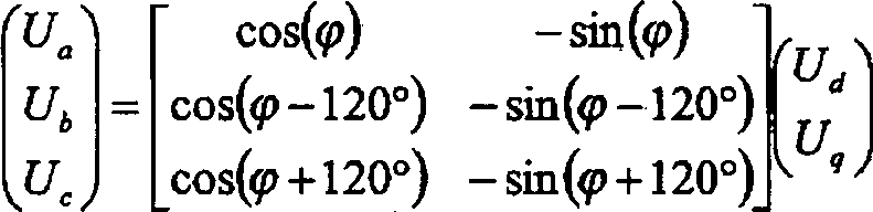
Eine Weiterbildung der Erfindung sieht vor, dass die elektrische Maschine in dem Notbetrieb ein Drehmoment erzeugt. Das Drehmoment soll dabei zumindest dem Vorzeichen nach einem angeforderten Drehmoment entsprechen. Wird also ein positives Drehmoment (Antriebsmoment) angefordert, so soll zumindest gewährleistet sein, dass die elektrische Maschine kein negatives Drehmoment (Bremsmoment) erzeugt.A development of the invention provides that the electric machine generates a torque in emergency operation. The torque should at least correspond to the sign after a requested torque. If, therefore, a positive torque (drive torque) is requested, it should at least be ensured that the electric machine does not generate a negative torque (braking torque).
Eine Weiterbildung der Erfindung sieht vor, dass wenn der Fehler einen fehlerhaften Schalter betrifft, ein erster Notbetriebsmodus ausgewählt wird. Wie vorstehend bereits dargelegt, kann ein solcher fehlerhafter Schalter entweder dauerhaft geschlossen oder dauerhaft geöffnet sein. In diesem Fall wird aus mehreren zur Verfügung stehenden Notbetriebsmodi der erste Notbetriebsmodus ausgewählt.A development of the invention provides that when the error relates to a faulty switch, a first emergency operating mode is selected. As already explained above, such a faulty switch can either be permanently closed or permanently open. In this case, the first emergency operating mode is selected from a plurality of available emergency operating modes.
Eine Weiterbildung der Erfindung sieht vor, dass in dem ersten Notbetriebsmodus ein weiterer, demselben Strang wie der fehlerhafte Schalter zugeordnete Schalter geöffnet oder geschlossen wird. Dies bedeutet insbesondere, dass bei einem defekten High-Side-Schalter der entsprechende Low-Side-Schalter desselben Strangs geöffnet beziehungsweise geschlossen wird und umgekehrt. Vorzugsweise ist es jedoch vorgesehen, dass wenn einer der Schalter dauerhaft leitend Ist, der jeweils andere Schalter geöffnet wird. Ist der Schalter dagegen dauerhaft geöffnet, also nicht leitend, so kann der jeweils andere Schalter geschlossen oder geöffnet werden. In letzterem Fall fließt in dem Strang, in welchem sich der fehlerhafte Schalter befindet, nur noch Strom über den eventuell vorhandenen Freilaufpfad des jeweils anderen, also intakten, Schalters. Die Schalter in der Brücke sollen also derart geschaltet sein, dass nicht beide Schalter gleichzeitig geschlossen beziehungsweise leitend sind, um einen Kurzschluss in dem Strang zu vermeiden. A further development of the invention provides that in the first emergency operating mode another, associated with the same strand as the faulty switch switch is opened or closed. This means, in particular, that in the case of a defective high-side switch, the corresponding low-side switch of the same string is opened or closed and vice versa. Preferably, however, it is provided that when one of the switches is permanently conductive, the respective other switch is opened. On the other hand, if the switch is permanently open, ie not conductive, the other switch can be closed or opened. In the latter case flows in the strand in which there is the faulty switch, only current on the possibly existing freewheeling path of the other, ie intact, switch. The switches in the bridge should therefore be switched such that not both switches are closed or conductive at the same time in order to avoid a short circuit in the string.
Eine Weiterbildung der Erfindung sieht vor, dass in dem ersten Notbetriebsmodus die Transformation unter Berücksichtigung des fehlerhaften Schalters durchgeführt wird. Ist beispielsweise der High-Side-Schalter eines Strangs dauerhaft leitend (womit die Strangspannung dieses Strangs gleich UB ist), dann wird dies bei der Transformation von den rotorfesten Stellgrößen auf die statorfesten Stellgrößen berücksichtigt. Ist der Strang, welcher mit der Strangspannung Uc beaufschlagt ist, betroffen, so ergeben sich für die beiden verbliebenen Zweige somit die statorfesten Stellgrößen Ua und Ub aus der Gleichung: 
Eine Weiterbildung der Erfindung sieht vor, dass wenn der Fehler einen Kurzschluss zwischen zwei Strängen betrifft, ein zweiter Notbetriebsmodus gewählt wird. Sobald festgestellt wird, dass der Kurzschluss vorliegt, so wird der Wechselrichter in dem Notbetrieb betrieben. Zu diesem Zweck wird der zweite Notbetriebsmodus ausgewählt.A development of the invention provides that when the fault relates to a short circuit between two strings, a second emergency mode is selected. Once it is determined that the short circuit is present, the inverter is operated in emergency mode. For this purpose, the second emergency mode is selected.
Eine Weiterbildung der Erfindung sieht vor, dass in dem zweiten Notbetriebsmodus nur eine der rotorfesten Stellgrößen, insbesondere eine drehmomentbildende Stellgröße, eingestellt wird. Bei einem Kurzschluss zwischen zwei Strängen steht bei einer dreiphasigen elektrischen Maschine – welche über drei Stränge verfügt – lediglich noch eine der rotorfesten Stellgrößen zur Verfügung. Lediglich diese kann zum Betreiben der elektrischen Maschine eingestellt beziehungsweise geregelt werden. In dem zweiten Notbetriebsmodus wird somit auf eine Regelung der elektrischen Maschine beziehungsweise des Wechselrichters umgeschaltet, bei welcher vorzugsweise lediglich die drehmomentbildende Stellgröße eingestellt wird. Eine feldbildende Stellgröße kann folglich nicht beeinflusst werden.A further development of the invention provides that only one of the rotor-fixed manipulated variables, in particular a torque-forming manipulated variable, is set in the second emergency operating mode. In the case of a short circuit between two strings, in the case of a three-phase electrical machine - which has three strings - only one of the rotor-fixed manipulated variables is available. Only this can be set or regulated to operate the electric machine. In the second emergency operating mode is thus switched to a control of the electric machine or the inverter, in which preferably only the torque-forming control variable is set. Consequently, a field-forming manipulated variable can not be influenced.
Eine Weiterbildung der Erfindung sieht vor, dass in dem zweiten Notbetriebsmodus anstatt der drehmomentbildenden Stellgröße zumindest vorübergehend eine feldbildende Stellgröße eingestellt wird, sobald diese einen Maximalwert erreicht. Da in dem zweiten Notbetriebsmodus lediglich die drehmomentbildende Stellgröße eingestellt wird, kann die feldbildende Stellgröße nicht direkt beeinflusst werden. Diese stellt sich vielmehr aufgrund der drehmomentbildenden Stellgröße ein. Üblicherweise darf die feldbildende Stellgröße jedoch einen bestimmten Maximalwert nicht überschreiten. Der Wert der feldbildenden Stellgröße muss demnach überwacht werden. Erreicht sie den Maximalwert, so kann zumindest vorübergehend auf die Regelung der feldbildenden Stellgröße umgeschaltet werden. Das bedeutet, dass nun nicht mehr die drehmomentbildende, sondern die feldbildende Stellgröße steuernd beziehungsweise regelnd eingestellt wird. Dabei kann es beispielsweise Ziel des Einstellens sein, die feldbildende Stellgröße auf einen Wert von Null zu führen. Hat die feldbildende Stellgröße einen hinreichend kleinen Wert erreicht, so kann wiederum auf das Einstellen der drehmomentbildenden Stellgröße umgeschaltet werden.A further development of the invention provides that in the second emergency operating mode instead of the torque-forming control variable at least temporarily a field-forming control variable is set as soon as it reaches a maximum value. Since only the torque-forming manipulated variable is set in the second emergency operating mode, the field-forming manipulated variable can not be directly influenced. This is due rather to the torque-forming manipulated variable. Usually, however, the field-forming manipulated variable must not exceed a certain maximum value. The value of the field-forming manipulated variable must therefore be monitored. If it reaches the maximum value, it is at least temporarily possible to switch over to the regulation of the field-forming manipulated variable. This means that now no longer the torque-forming, but the field-forming manipulated variable is controlled or regulated. In this case, it may be the aim of setting, for example, to lead the field-forming manipulated variable to a value of zero. If the field-forming manipulated variable has reached a sufficiently low value, it is again possible to switch over to setting the torque-forming manipulated variable.
Die Erfindung betrifft weiterhin ein Antriebsaggregat, insbesondere zur Umsetzung des vorstehend beschriebenen Verfahrens, mit einer elektrischen Maschine, die in einem Normalbetrieb mit von einem Wechselrichter an mindestens zwei Strängen bereitgestelltem Strom betreibbar ist, wobei an den Strängen bestimmte Strangspannungen für die elektrische Maschine eingestellt werden. Dabei ist vorgesehen, dass der Wechselrichter zum weiteren Betreiben der elektrischen Maschine nach Auftreten eines Fehlers des Wechselrichters in einem Notbetrieb betreibbar ist. Die elektrische Maschine muss also nicht, wie aus dem Stand der Technik bekannt, bei Auftreten des Fehlers des Wechselrichters von diesem elektrisch getrennt werden, um ein ungünstiges Verhalten der elektrischen Maschine zu vermeiden. Es ist insbesondere vorgesehen, dass die elektrische Maschine das angeforderte Drehmoment zumindest teilweise erzeugt.The invention further relates to a drive unit, in particular for implementing the above-described method, with an electrical machine which is operable in a normal operation with provided by an inverter at least two lines current, wherein the strand specific strand voltages are set for the electric machine. It is provided that the inverter for further operation of the electric machine after occurrence of a fault of the inverter in an emergency operation is operable. Thus, as is known from the prior art, the electrical machine does not have to be electrically disconnected from the inverter when the fault of the inverter occurs in order to avoid unfavorable behavior of the electrical machine. It is provided in particular that the electrical machine generates the requested torque at least partially.
Eine Weiterbildung der Erfindung sieht vor, dass die elektrische Maschine ein Elektromotor, insbesondere eine permanenterregte Synchronmaschine, ist. Die elektrische Maschine ist dabei Bestandteil des Antriebsaggregats, welches im Wesentlichen aus der elektrischen Maschine und dem Wechselrichter sowie zu deren Ansteuerung benötigten Elektronik besteht.A development of the invention provides that the electric machine is an electric motor, in particular a permanent-magnet synchronous machine. The electric machine is part of the drive unit, which consists essentially of the electrical machine and the inverter and the electronics required for their control.
Eine Weiterbildung der Erfindung sieht vor, dass das Antriebsaggregat zum Einsatz in einer Servolenkung oder einem Kraftfahrzeugantrieb vorgesehen ist. Die Servolenkung ist dabei eine elektrisch unterstützte Servolenkung, wobei mittels des Antriebsaggregats das zum Lenken eines Kraftfahrzeugs benötigte Drehmoment erzeugt wird. Der Kraftfahrzeugantrieb kann beispielsweise rein elektrisch oder als Hybridantrieb ausgebildet sein. In ersterem Fall dient allein das Antriebsaggregat einem Antrieb des Kraftfahrzeugs. Im Falle des Hybridantriebs wird das Antriebsaggregat mit einer weiteren drehmomenterzeugenden Maschine, beispielsweise einer Brennkraftmaschine, kombiniert.A development of the invention provides that the drive unit is provided for use in a power steering or a motor vehicle drive. The power steering is an electrically assisted power steering, which required by means of the drive unit for steering a motor vehicle Torque is generated. The motor vehicle drive may be designed, for example, purely electrically or as a hybrid drive. In the former case, only the drive unit serves a drive of the motor vehicle. In the case of the hybrid drive, the drive unit is combined with another torque-generating machine, for example an internal combustion engine.
Die Erfindung wird im Folgenden anhand der in der Zeichnung dargestellten Ausführungsbeispiele näher erläutert, ohne dass eine Beschränkung der Erfindung erfolgt. Dabei zeigt die einzigeThe invention will be explained in more detail below with reference to the embodiments illustrated in the drawing, without any limitation of the invention. The only one shows
Figur ein Antriebsaggregat mit einer elektrischen Maschine und einem Wechselrichter.Figure a drive unit with an electric machine and an inverter.
Die Figur zeigt ein Antriebsaggregat
Jedem der Stränge
In einem Normalbetrieb der elektrischen Maschine 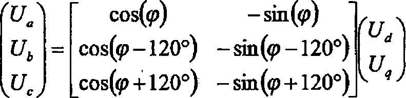
Liegt ein Fehler des Wechselrichters
Ist der High-Side-Schalter ![]()
![]()
Die statorfesten Stellgrößen Ua, Ub sowie Uc = UB werden anschließend über Pulsweitenmodulation der Schalter
Ist dagegen der High-Side-Schalter
Liegt hingegen ein Kurzschluss zwischen zwei der Strängen
Dabei darf jedoch üblicherweise die feldbildende Stellgröße Id einen bestimmten Maximalwert nicht überschreiten. Kommt die feldbildende Stellgröße Id in den Bereich dieses Maximalwerts, so kann beispielsweise auf eine Regelung, insbesondere der drehmomentbildenden Stellgröße Iq, umgeschaltet werden, die diese auf Null zurückregelt. Ist die feldbildende Stellgröße Id hinreichend klein, so kann wieder auf das Einstellen der drehmomentbildenden Stellgröße Iq gewechselt werden.However, usually the field-forming manipulated variable I d must not exceed a certain maximum value. If the field-forming manipulated variable I d comes within the range of this maximum value, it is possible, for example, to switch over to a control, in particular the torque-forming manipulated variable I q , which regulates this back to zero. If the field-forming manipulated variable I d is sufficiently small, the setting of the torque-forming manipulated variable I q can be changed again.
Bei der Umsetzung des beschriebenen Verfahrens kann jedem Notbetriebsmodus eine eigenständige Regeleinrichtung für die elektrische Maschine beziehungsweise für den Wechselrichter zugeordnet werden und bei Auftreten des Fehlers zwischen diesen Regeleinrichtungen umgeschaltet werden. Die Funktion kann jedoch auch mittels einer einzigen Regeleinrichtung realisiert sein.In the implementation of the method described, each emergency operating mode can be assigned an independent control device for the electric machine or for the inverter and can be switched over when the fault occurs between these control devices. However, the function can also be realized by means of a single control device.
ZITATE ENTHALTEN IN DER BESCHREIBUNG QUOTES INCLUDE IN THE DESCRIPTION
Diese Liste der vom Anmelder aufgeführten Dokumente wurde automatisiert erzeugt und ist ausschließlich zur besseren Information des Lesers aufgenommen. Die Liste ist nicht Bestandteil der deutschen Patent- bzw. Gebrauchsmusteranmeldung. Das DPMA übernimmt keinerlei Haftung für etwaige Fehler oder Auslassungen.This list of the documents listed by the applicant has been generated automatically and is included solely for the better information of the reader. The list is not part of the German patent or utility model application. The DPMA assumes no liability for any errors or omissions.
Zitierte PatentliteraturCited patent literature
- WO 98/10971 A1 [0002] WO 98/10971 A1 [0002]
- DE 19849889 A1 [0002] DE 19849889 A1 [0002]
Claims (13)
Priority Applications (3)
| Application Number | Priority Date | Filing Date | Title |
|---|---|---|---|
| DE102009045351A DE102009045351A1 (en) | 2009-10-06 | 2009-10-06 | Method for operating a drive unit and drive unit |
| PCT/EP2010/061603 WO2011042237A1 (en) | 2009-10-06 | 2010-08-10 | Method for operating a drive unit, and a drive unit |
| US13/500,003 US8786226B2 (en) | 2009-10-06 | 2010-08-10 | Method for operating a drive unit, and a drive unit |
Applications Claiming Priority (1)
| Application Number | Priority Date | Filing Date | Title |
|---|---|---|---|
| DE102009045351A DE102009045351A1 (en) | 2009-10-06 | 2009-10-06 | Method for operating a drive unit and drive unit |
Publications (1)
| Publication Number | Publication Date |
|---|---|
| DE102009045351A1 true DE102009045351A1 (en) | 2011-04-14 |
Family
ID=42829275
Family Applications (1)
| Application Number | Title | Priority Date | Filing Date |
|---|---|---|---|
| DE102009045351A Pending DE102009045351A1 (en) | 2009-10-06 | 2009-10-06 | Method for operating a drive unit and drive unit |
Country Status (3)
| Country | Link |
|---|---|
| US (1) | US8786226B2 (en) |
| DE (1) | DE102009045351A1 (en) |
| WO (1) | WO2011042237A1 (en) |
Cited By (8)
| Publication number | Priority date | Publication date | Assignee | Title |
|---|---|---|---|---|
| WO2011117311A3 (en) * | 2010-03-23 | 2012-07-26 | Continental Automotive Gmbh | Method for operating a brushless electric motor |
| DE102013223476A1 (en) * | 2013-11-18 | 2015-02-26 | Zf Friedrichshafen Ag | Control device and method for providing a setpoint torque specification for a synchronous machine |
| US9093929B2 (en) | 2012-12-17 | 2015-07-28 | Infineon Technologies Ag | Circuit arrangements and methods for operating an electrical machine |
| US9543857B2 (en) | 2014-03-28 | 2017-01-10 | Omron Automotive Electronics Co., Ltd. | Load driving device with failure detection |
| DE102015220222A1 (en) * | 2015-10-16 | 2017-04-20 | Zf Friedrichshafen Ag | Method, computer program and device for controlling a multiphase induction machine with interruption of a current of at least one phase of the induction machine |
| WO2021144234A1 (en) | 2020-01-13 | 2021-07-22 | Convertertec Deutschland Gmbh | Method for phase-separated overcurrent protection of a three-phase bridge circuit |
| DE102020112704A1 (en) | 2020-05-11 | 2021-11-11 | Audi Aktiengesellschaft | Method for operating an electrical circuit arrangement, electrical circuit arrangement and motor vehicle |
| DE102023205559B3 (en) | 2023-06-14 | 2024-11-07 | Audi Aktiengesellschaft | Emergency mode in case of defective excitation circuit for a separately excited synchronous machine (FSM) |
Families Citing this family (4)
| Publication number | Priority date | Publication date | Assignee | Title |
|---|---|---|---|---|
| DE102012208747A1 (en) | 2012-05-24 | 2013-11-28 | Zf Friedrichshafen Ag | Method for operating permanent-magnet synchronous machine for e.g. electric drive of automobile, involves providing pulse width modulation default values for phases of machine upon detection of short circuit at power switches of phases |
| JP2014241690A (en) * | 2013-06-12 | 2014-12-25 | トヨタ自動車株式会社 | vehicle |
| JP6531728B2 (en) * | 2016-07-15 | 2019-06-19 | 株式会社デンソー | Electric rotating machine |
| CN108736791B (en) * | 2017-04-20 | 2022-03-29 | 通用电气公司 | Vehicle and control method and system thereof |
Citations (2)
| Publication number | Priority date | Publication date | Assignee | Title |
|---|---|---|---|---|
| WO1998010971A1 (en) | 1996-09-13 | 1998-03-19 | Lucas Industries Public Limited Company | Electrical power-assisted steering systems |
| DE19849889A1 (en) | 1998-10-29 | 2000-05-04 | Bosch Gmbh Robert | Process for the performance and efficiency-optimized control of synchronous machines |
Family Cites Families (21)
| Publication number | Priority date | Publication date | Assignee | Title |
|---|---|---|---|---|
| JPS6234861A (en) * | 1985-08-06 | 1987-02-14 | Nissan Motor Co Ltd | Four-wheel steering device for car |
| US5491622A (en) * | 1994-01-07 | 1996-02-13 | Delco Electronics Corp. | Power converter with emergency operating mode for three phase induction motors |
| JP3257971B2 (en) * | 1997-09-12 | 2002-02-18 | 本田技研工業株式会社 | Electric power steering device |
| GB2341587B (en) * | 1998-09-17 | 2000-12-06 | Daimler Chrysler Ag | Method for operating a steering system for a vehicle |
| DE10101827A1 (en) * | 2001-01-17 | 2002-07-18 | Daimler Chrysler Ag | Steering arrangement for motor vehicles |
| JP2004018254A (en) * | 2002-06-20 | 2004-01-22 | Mitsubishi Electric Corp | Elevator control device |
| US6683435B1 (en) * | 2002-06-21 | 2004-01-27 | Ford Motor Company | Electrical machine drive method and system |
| US20040264075A1 (en) * | 2003-06-30 | 2004-12-30 | Valeo Electrical Systems, Inc. | Steering assist system |
| JP2005094873A (en) * | 2003-09-16 | 2005-04-07 | Nissan Motor Co Ltd | Control device for three-phase AC motor |
| JP2007225388A (en) * | 2006-02-22 | 2007-09-06 | Nsk Ltd | Electric power steering device |
| JP5070867B2 (en) * | 2007-02-05 | 2012-11-14 | 株式会社ジェイテクト | Motor control device and electric power steering device |
| JP2008211910A (en) * | 2007-02-26 | 2008-09-11 | Jtekt Corp | Motor control device and electric power steering device |
| JP2008211909A (en) * | 2007-02-26 | 2008-09-11 | Jtekt Corp | Motor control device and electric power steering device |
| JP5056175B2 (en) * | 2007-06-01 | 2012-10-24 | 株式会社ジェイテクト | Motor control device and electric power steering device |
| JP5233178B2 (en) * | 2007-06-14 | 2013-07-10 | 株式会社ジェイテクト | Motor control device and electric power steering device |
| US7990094B2 (en) * | 2007-06-20 | 2011-08-02 | Jtekt Corporation | Motor controller and electric power steering apparatus |
| JP2009071975A (en) * | 2007-09-13 | 2009-04-02 | Daikin Ind Ltd | Inverter device and power steering device using the same |
| JP4609474B2 (en) * | 2007-10-10 | 2011-01-12 | 株式会社デンソー | Rotating electrical machine equipment |
| JP5029312B2 (en) * | 2007-11-20 | 2012-09-19 | 株式会社ジェイテクト | Electric power steering device |
| US8116945B2 (en) * | 2008-01-16 | 2012-02-14 | Jtekt Corporation | Electric power steering device |
| JP5157517B2 (en) * | 2008-01-21 | 2013-03-06 | 株式会社ジェイテクト | Electric power steering device |
-
2009
- 2009-10-06 DE DE102009045351A patent/DE102009045351A1/en active Pending
-
2010
- 2010-08-10 WO PCT/EP2010/061603 patent/WO2011042237A1/en not_active Ceased
- 2010-08-10 US US13/500,003 patent/US8786226B2/en active Active
Patent Citations (2)
| Publication number | Priority date | Publication date | Assignee | Title |
|---|---|---|---|---|
| WO1998010971A1 (en) | 1996-09-13 | 1998-03-19 | Lucas Industries Public Limited Company | Electrical power-assisted steering systems |
| DE19849889A1 (en) | 1998-10-29 | 2000-05-04 | Bosch Gmbh Robert | Process for the performance and efficiency-optimized control of synchronous machines |
Cited By (14)
| Publication number | Priority date | Publication date | Assignee | Title |
|---|---|---|---|---|
| US9041326B2 (en) | 2010-03-23 | 2015-05-26 | Continental Automotive Gmbh | Method for operating a brushless electric motor |
| WO2011117311A3 (en) * | 2010-03-23 | 2012-07-26 | Continental Automotive Gmbh | Method for operating a brushless electric motor |
| DE102013112147B4 (en) * | 2012-12-17 | 2021-05-12 | Infineon Technologies Ag | CIRCUIT ARRANGEMENTS AND METHODS OF OPERATING AN ELECTRIC MACHINE |
| US9093929B2 (en) | 2012-12-17 | 2015-07-28 | Infineon Technologies Ag | Circuit arrangements and methods for operating an electrical machine |
| DE102013223476A1 (en) * | 2013-11-18 | 2015-02-26 | Zf Friedrichshafen Ag | Control device and method for providing a setpoint torque specification for a synchronous machine |
| US9543857B2 (en) | 2014-03-28 | 2017-01-10 | Omron Automotive Electronics Co., Ltd. | Load driving device with failure detection |
| DE102015205627B4 (en) * | 2014-03-28 | 2021-07-01 | Omron Automotive Electronics Co., Ltd. | Load drive device |
| DE102015220222A1 (en) * | 2015-10-16 | 2017-04-20 | Zf Friedrichshafen Ag | Method, computer program and device for controlling a multiphase induction machine with interruption of a current of at least one phase of the induction machine |
| DE102015220222B4 (en) * | 2015-10-16 | 2025-04-17 | Robert Bosch Gmbh | Method, computer program and device for controlling a multi-phase rotating field machine in the event of an interruption of a current in at least one phase of the rotating field machine |
| WO2021144234A1 (en) | 2020-01-13 | 2021-07-22 | Convertertec Deutschland Gmbh | Method for phase-separated overcurrent protection of a three-phase bridge circuit |
| US11990834B2 (en) | 2020-01-13 | 2024-05-21 | Kk Wind Solutions A/S | Method for phase-separated overcurrent protection of a three-phase bridge circuit |
| DE102020112704A1 (en) | 2020-05-11 | 2021-11-11 | Audi Aktiengesellschaft | Method for operating an electrical circuit arrangement, electrical circuit arrangement and motor vehicle |
| DE102020112704B4 (en) | 2020-05-11 | 2023-01-26 | Audi Aktiengesellschaft | Electrical circuit arrangement, electrical machine and motor vehicle |
| DE102023205559B3 (en) | 2023-06-14 | 2024-11-07 | Audi Aktiengesellschaft | Emergency mode in case of defective excitation circuit for a separately excited synchronous machine (FSM) |
Also Published As
| Publication number | Publication date |
|---|---|
| WO2011042237A1 (en) | 2011-04-14 |
| US8786226B2 (en) | 2014-07-22 |
| US20120262098A1 (en) | 2012-10-18 |
Similar Documents
| Publication | Publication Date | Title |
|---|---|---|
| DE102009045351A1 (en) | Method for operating a drive unit and drive unit | |
| DE102010001250B4 (en) | On-board electrical system and method for operating an on-board electrical system | |
| EP2776272A2 (en) | Method and apparatus for controlling an electrical machine | |
| DE102011085731A1 (en) | Electrical system | |
| DE102010030856A1 (en) | Method for operating an at least three-phase electric machine serving as drive unit in a motor vehicle and control unit for an inverter | |
| DE102013226560A1 (en) | Apparatus and method for operating an electrical machine | |
| DE102013200637A1 (en) | A method of detecting an electrical fault in a generator assembly and means for implementing it | |
| WO2014140068A2 (en) | Method and device for operating an on-board power system | |
| WO2018099701A1 (en) | Method for switching off a current-excited synchronous machine of a motor vehicle | |
| DE102020120814A1 (en) | Method for checking a fast de-excitation path of an excitation circuit and corresponding excitation circuit | |
| DE102011075789A1 (en) | Method for operating induction machine e.g. permanent magnet synchronous machine of pulse inverter for motor car, involves adjusting voltage vector and setting pulse width modulation command value constant for defective power switch | |
| EP2673876B1 (en) | Energy storage device for a separately excited electrical machine | |
| DE102011003940A1 (en) | System with an electrically excited machine | |
| WO2015000669A1 (en) | Avoiding braking torques in permanent magnet synchronous machines | |
| DE102020210097A1 (en) | Method for operating a drive device, drive device, motor vehicle | |
| DE102021129144B4 (en) | Method for operating an electrical circuit arrangement, electrical circuit and motor vehicle | |
| DE102011003946A1 (en) | A method for controlling an output from an electric machine in a motor vehicle actual torque to a desired torque | |
| DE102016110870A1 (en) | Charging system for charging a high-voltage battery of an electrically driven vehicle | |
| EP3893386A1 (en) | Control device, control circuit and motor vehicle | |
| DE102017131115B4 (en) | DIAGNOSTIC DEVICE | |
| DE102016202169A1 (en) | Operating an arrangement of generator-operated electrical machine and active bridge rectifier | |
| DE102015202912B3 (en) | Method and device for driving an active bridge rectifier when canceling a phase short circuit | |
| DE102015211248A1 (en) | Method for operating a separately excited electrical machine | |
| DE102018214830A1 (en) | Method for operating an electrical system | |
| DE102018004232A1 (en) | Method for operating a drive device of a motor vehicle having at least one electric machine |
Legal Events
| Date | Code | Title | Description |
|---|---|---|---|
| R012 | Request for examination validly filed | ||
| R016 | Response to examination communication | ||
| R084 | Declaration of willingness to licence |