DE102009035370A1 - lamp - Google Patents
lamp Download PDFInfo
- Publication number
- DE102009035370A1 DE102009035370A1 DE102009035370A DE102009035370A DE102009035370A1 DE 102009035370 A1 DE102009035370 A1 DE 102009035370A1 DE 102009035370 A DE102009035370 A DE 102009035370A DE 102009035370 A DE102009035370 A DE 102009035370A DE 102009035370 A1 DE102009035370 A1 DE 102009035370A1
- Authority
- DE
- Germany
- Prior art keywords
- cover
- heat sink
- lamp
- wall thickness
- heat
- Prior art date
- Legal status (The legal status is an assumption and is not a legal conclusion. Google has not performed a legal analysis and makes no representation as to the accuracy of the status listed.)
- Ceased
Links
- 239000004065 semiconductor Substances 0.000 claims abstract description 7
- 239000000853 adhesive Substances 0.000 claims description 18
- 230000001070 adhesive effect Effects 0.000 claims description 18
- 239000011521 glass Substances 0.000 claims description 11
- 230000003716 rejuvenation Effects 0.000 claims description 5
- 230000003287 optical effect Effects 0.000 claims description 3
- 230000017525 heat dissipation Effects 0.000 description 17
- 238000001816 cooling Methods 0.000 description 13
- 239000000758 substrate Substances 0.000 description 9
- 239000004033 plastic Substances 0.000 description 5
- 238000012546 transfer Methods 0.000 description 5
- 239000012790 adhesive layer Substances 0.000 description 4
- 230000008901 benefit Effects 0.000 description 4
- 238000013461 design Methods 0.000 description 4
- 238000001746 injection moulding Methods 0.000 description 4
- 238000004519 manufacturing process Methods 0.000 description 4
- 238000003825 pressing Methods 0.000 description 4
- 239000003570 air Substances 0.000 description 3
- 239000000919 ceramic Substances 0.000 description 3
- 230000008859 change Effects 0.000 description 3
- 238000009826 distribution Methods 0.000 description 3
- 230000000694 effects Effects 0.000 description 3
- 230000004907 flux Effects 0.000 description 3
- 239000000463 material Substances 0.000 description 3
- 238000000034 method Methods 0.000 description 3
- 230000008569 process Effects 0.000 description 3
- 238000013459 approach Methods 0.000 description 2
- 230000005540 biological transmission Effects 0.000 description 2
- 239000004020 conductor Substances 0.000 description 2
- NJPPVKZQTLUDBO-UHFFFAOYSA-N novaluron Chemical compound C1=C(Cl)C(OC(F)(F)C(OC(F)(F)F)F)=CC=C1NC(=O)NC(=O)C1=C(F)C=CC=C1F NJPPVKZQTLUDBO-UHFFFAOYSA-N 0.000 description 2
- 238000005457 optimization Methods 0.000 description 2
- 238000002360 preparation method Methods 0.000 description 2
- 230000009467 reduction Effects 0.000 description 2
- BUHVIAUBTBOHAG-FOYDDCNASA-N (2r,3r,4s,5r)-2-[6-[[2-(3,5-dimethoxyphenyl)-2-(2-methylphenyl)ethyl]amino]purin-9-yl]-5-(hydroxymethyl)oxolane-3,4-diol Chemical compound COC1=CC(OC)=CC(C(CNC=2C=3N=CN(C=3N=CN=2)[C@H]2[C@@H]([C@H](O)[C@@H](CO)O2)O)C=2C(=CC=CC=2)C)=C1 BUHVIAUBTBOHAG-FOYDDCNASA-N 0.000 description 1
- BQCADISMDOOEFD-UHFFFAOYSA-N Silver Chemical compound [Ag] BQCADISMDOOEFD-UHFFFAOYSA-N 0.000 description 1
- 239000006094 Zerodur Substances 0.000 description 1
- 230000004308 accommodation Effects 0.000 description 1
- 230000032683 aging Effects 0.000 description 1
- 239000012080 ambient air Substances 0.000 description 1
- 229910010293 ceramic material Inorganic materials 0.000 description 1
- 238000012937 correction Methods 0.000 description 1
- 238000005520 cutting process Methods 0.000 description 1
- 230000007423 decrease Effects 0.000 description 1
- 230000003247 decreasing effect Effects 0.000 description 1
- 230000001419 dependent effect Effects 0.000 description 1
- 239000005357 flat glass Substances 0.000 description 1
- 239000003292 glue Substances 0.000 description 1
- 230000006872 improvement Effects 0.000 description 1
- 238000009413 insulation Methods 0.000 description 1
- 229910052574 oxide ceramic Inorganic materials 0.000 description 1
- 239000011224 oxide ceramic Substances 0.000 description 1
- TWNQGVIAIRXVLR-UHFFFAOYSA-N oxo(oxoalumanyloxy)alumane Chemical compound O=[Al]O[Al]=O TWNQGVIAIRXVLR-UHFFFAOYSA-N 0.000 description 1
- 239000004417 polycarbonate Substances 0.000 description 1
- 229920000515 polycarbonate Polymers 0.000 description 1
- 230000005855 radiation Effects 0.000 description 1
- 229910052709 silver Inorganic materials 0.000 description 1
- 239000004332 silver Substances 0.000 description 1
- 239000011343 solid material Substances 0.000 description 1
- 238000010792 warming Methods 0.000 description 1
Images


Classifications
-
- F—MECHANICAL ENGINEERING; LIGHTING; HEATING; WEAPONS; BLASTING
- F21—LIGHTING
- F21K—NON-ELECTRIC LIGHT SOURCES USING LUMINESCENCE; LIGHT SOURCES USING ELECTROCHEMILUMINESCENCE; LIGHT SOURCES USING CHARGES OF COMBUSTIBLE MATERIAL; LIGHT SOURCES USING SEMICONDUCTOR DEVICES AS LIGHT-GENERATING ELEMENTS; LIGHT SOURCES NOT OTHERWISE PROVIDED FOR
- F21K9/00—Light sources using semiconductor devices as light-generating elements, e.g. using light-emitting diodes [LED] or lasers
- F21K9/20—Light sources comprising attachment means
- F21K9/23—Retrofit light sources for lighting devices with a single fitting for each light source, e.g. for substitution of incandescent lamps with bayonet or threaded fittings
- F21K9/232—Retrofit light sources for lighting devices with a single fitting for each light source, e.g. for substitution of incandescent lamps with bayonet or threaded fittings specially adapted for generating an essentially omnidirectional light distribution, e.g. with a glass bulb
-
- F—MECHANICAL ENGINEERING; LIGHTING; HEATING; WEAPONS; BLASTING
- F21—LIGHTING
- F21V—FUNCTIONAL FEATURES OR DETAILS OF LIGHTING DEVICES OR SYSTEMS THEREOF; STRUCTURAL COMBINATIONS OF LIGHTING DEVICES WITH OTHER ARTICLES, NOT OTHERWISE PROVIDED FOR
- F21V29/00—Protecting lighting devices from thermal damage; Cooling or heating arrangements specially adapted for lighting devices or systems
- F21V29/50—Cooling arrangements
- F21V29/502—Cooling arrangements characterised by the adaptation for cooling of specific components
- F21V29/506—Cooling arrangements characterised by the adaptation for cooling of specific components of globes, bowls or cover glasses
-
- F—MECHANICAL ENGINEERING; LIGHTING; HEATING; WEAPONS; BLASTING
- F21—LIGHTING
- F21V—FUNCTIONAL FEATURES OR DETAILS OF LIGHTING DEVICES OR SYSTEMS THEREOF; STRUCTURAL COMBINATIONS OF LIGHTING DEVICES WITH OTHER ARTICLES, NOT OTHERWISE PROVIDED FOR
- F21V3/00—Globes; Bowls; Cover glasses
- F21V3/02—Globes; Bowls; Cover glasses characterised by the shape
-
- F—MECHANICAL ENGINEERING; LIGHTING; HEATING; WEAPONS; BLASTING
- F21—LIGHTING
- F21K—NON-ELECTRIC LIGHT SOURCES USING LUMINESCENCE; LIGHT SOURCES USING ELECTROCHEMILUMINESCENCE; LIGHT SOURCES USING CHARGES OF COMBUSTIBLE MATERIAL; LIGHT SOURCES USING SEMICONDUCTOR DEVICES AS LIGHT-GENERATING ELEMENTS; LIGHT SOURCES NOT OTHERWISE PROVIDED FOR
- F21K9/00—Light sources using semiconductor devices as light-generating elements, e.g. using light-emitting diodes [LED] or lasers
- F21K9/20—Light sources comprising attachment means
- F21K9/23—Retrofit light sources for lighting devices with a single fitting for each light source, e.g. for substitution of incandescent lamps with bayonet or threaded fittings
- F21K9/233—Retrofit light sources for lighting devices with a single fitting for each light source, e.g. for substitution of incandescent lamps with bayonet or threaded fittings specially adapted for generating a spot light distribution, e.g. for substitution of reflector lamps
-
- F—MECHANICAL ENGINEERING; LIGHTING; HEATING; WEAPONS; BLASTING
- F21—LIGHTING
- F21K—NON-ELECTRIC LIGHT SOURCES USING LUMINESCENCE; LIGHT SOURCES USING ELECTROCHEMILUMINESCENCE; LIGHT SOURCES USING CHARGES OF COMBUSTIBLE MATERIAL; LIGHT SOURCES USING SEMICONDUCTOR DEVICES AS LIGHT-GENERATING ELEMENTS; LIGHT SOURCES NOT OTHERWISE PROVIDED FOR
- F21K9/00—Light sources using semiconductor devices as light-generating elements, e.g. using light-emitting diodes [LED] or lasers
- F21K9/20—Light sources comprising attachment means
- F21K9/27—Retrofit light sources for lighting devices with two fittings for each light source, e.g. for substitution of fluorescent tubes
-
- F—MECHANICAL ENGINEERING; LIGHTING; HEATING; WEAPONS; BLASTING
- F21—LIGHTING
- F21K—NON-ELECTRIC LIGHT SOURCES USING LUMINESCENCE; LIGHT SOURCES USING ELECTROCHEMILUMINESCENCE; LIGHT SOURCES USING CHARGES OF COMBUSTIBLE MATERIAL; LIGHT SOURCES USING SEMICONDUCTOR DEVICES AS LIGHT-GENERATING ELEMENTS; LIGHT SOURCES NOT OTHERWISE PROVIDED FOR
- F21K9/00—Light sources using semiconductor devices as light-generating elements, e.g. using light-emitting diodes [LED] or lasers
- F21K9/60—Optical arrangements integrated in the light source, e.g. for improving the colour rendering index or the light extraction
- F21K9/66—Details of globes or covers forming part of the light source
-
- F—MECHANICAL ENGINEERING; LIGHTING; HEATING; WEAPONS; BLASTING
- F21—LIGHTING
- F21V—FUNCTIONAL FEATURES OR DETAILS OF LIGHTING DEVICES OR SYSTEMS THEREOF; STRUCTURAL COMBINATIONS OF LIGHTING DEVICES WITH OTHER ARTICLES, NOT OTHERWISE PROVIDED FOR
- F21V17/00—Fastening of component parts of lighting devices, e.g. shades, globes, refractors, reflectors, filters, screens, grids or protective cages
- F21V17/10—Fastening of component parts of lighting devices, e.g. shades, globes, refractors, reflectors, filters, screens, grids or protective cages characterised by specific fastening means or way of fastening
- F21V17/101—Fastening of component parts of lighting devices, e.g. shades, globes, refractors, reflectors, filters, screens, grids or protective cages characterised by specific fastening means or way of fastening permanently, e.g. welding, gluing or riveting
-
- F—MECHANICAL ENGINEERING; LIGHTING; HEATING; WEAPONS; BLASTING
- F21—LIGHTING
- F21V—FUNCTIONAL FEATURES OR DETAILS OF LIGHTING DEVICES OR SYSTEMS THEREOF; STRUCTURAL COMBINATIONS OF LIGHTING DEVICES WITH OTHER ARTICLES, NOT OTHERWISE PROVIDED FOR
- F21V29/00—Protecting lighting devices from thermal damage; Cooling or heating arrangements specially adapted for lighting devices or systems
- F21V29/50—Cooling arrangements
- F21V29/70—Cooling arrangements characterised by passive heat-dissipating elements, e.g. heat-sinks
- F21V29/74—Cooling arrangements characterised by passive heat-dissipating elements, e.g. heat-sinks with fins or blades
- F21V29/75—Cooling arrangements characterised by passive heat-dissipating elements, e.g. heat-sinks with fins or blades with fins or blades having different shapes, thicknesses or spacing
-
- F—MECHANICAL ENGINEERING; LIGHTING; HEATING; WEAPONS; BLASTING
- F21—LIGHTING
- F21V—FUNCTIONAL FEATURES OR DETAILS OF LIGHTING DEVICES OR SYSTEMS THEREOF; STRUCTURAL COMBINATIONS OF LIGHTING DEVICES WITH OTHER ARTICLES, NOT OTHERWISE PROVIDED FOR
- F21V29/00—Protecting lighting devices from thermal damage; Cooling or heating arrangements specially adapted for lighting devices or systems
- F21V29/50—Cooling arrangements
- F21V29/70—Cooling arrangements characterised by passive heat-dissipating elements, e.g. heat-sinks
- F21V29/74—Cooling arrangements characterised by passive heat-dissipating elements, e.g. heat-sinks with fins or blades
- F21V29/76—Cooling arrangements characterised by passive heat-dissipating elements, e.g. heat-sinks with fins or blades with essentially identical parallel planar fins or blades, e.g. with comb-like cross-section
- F21V29/763—Cooling arrangements characterised by passive heat-dissipating elements, e.g. heat-sinks with fins or blades with essentially identical parallel planar fins or blades, e.g. with comb-like cross-section the planes containing the fins or blades having the direction of the light emitting axis
-
- F—MECHANICAL ENGINEERING; LIGHTING; HEATING; WEAPONS; BLASTING
- F21—LIGHTING
- F21V—FUNCTIONAL FEATURES OR DETAILS OF LIGHTING DEVICES OR SYSTEMS THEREOF; STRUCTURAL COMBINATIONS OF LIGHTING DEVICES WITH OTHER ARTICLES, NOT OTHERWISE PROVIDED FOR
- F21V29/00—Protecting lighting devices from thermal damage; Cooling or heating arrangements specially adapted for lighting devices or systems
- F21V29/85—Protecting lighting devices from thermal damage; Cooling or heating arrangements specially adapted for lighting devices or systems characterised by the material
- F21V29/86—Ceramics or glass
-
- F—MECHANICAL ENGINEERING; LIGHTING; HEATING; WEAPONS; BLASTING
- F21—LIGHTING
- F21V—FUNCTIONAL FEATURES OR DETAILS OF LIGHTING DEVICES OR SYSTEMS THEREOF; STRUCTURAL COMBINATIONS OF LIGHTING DEVICES WITH OTHER ARTICLES, NOT OTHERWISE PROVIDED FOR
- F21V3/00—Globes; Bowls; Cover glasses
- F21V3/04—Globes; Bowls; Cover glasses characterised by materials, surface treatments or coatings
- F21V3/06—Globes; Bowls; Cover glasses characterised by materials, surface treatments or coatings characterised by the material
-
- F—MECHANICAL ENGINEERING; LIGHTING; HEATING; WEAPONS; BLASTING
- F21—LIGHTING
- F21Y—INDEXING SCHEME ASSOCIATED WITH SUBCLASSES F21K, F21L, F21S and F21V, RELATING TO THE FORM OR THE KIND OF THE LIGHT SOURCES OR OF THE COLOUR OF THE LIGHT EMITTED
- F21Y2103/00—Elongate light sources, e.g. fluorescent tubes
- F21Y2103/10—Elongate light sources, e.g. fluorescent tubes comprising a linear array of point-like light-generating elements
-
- F—MECHANICAL ENGINEERING; LIGHTING; HEATING; WEAPONS; BLASTING
- F21—LIGHTING
- F21Y—INDEXING SCHEME ASSOCIATED WITH SUBCLASSES F21K, F21L, F21S and F21V, RELATING TO THE FORM OR THE KIND OF THE LIGHT SOURCES OR OF THE COLOUR OF THE LIGHT EMITTED
- F21Y2115/00—Light-generating elements of semiconductor light sources
- F21Y2115/10—Light-emitting diodes [LED]
Landscapes
- Engineering & Computer Science (AREA)
- General Engineering & Computer Science (AREA)
- Physics & Mathematics (AREA)
- Microelectronics & Electronic Packaging (AREA)
- Optics & Photonics (AREA)
- Arrangement Of Elements, Cooling, Sealing, Or The Like Of Lighting Devices (AREA)
- Non-Portable Lighting Devices Or Systems Thereof (AREA)
Abstract
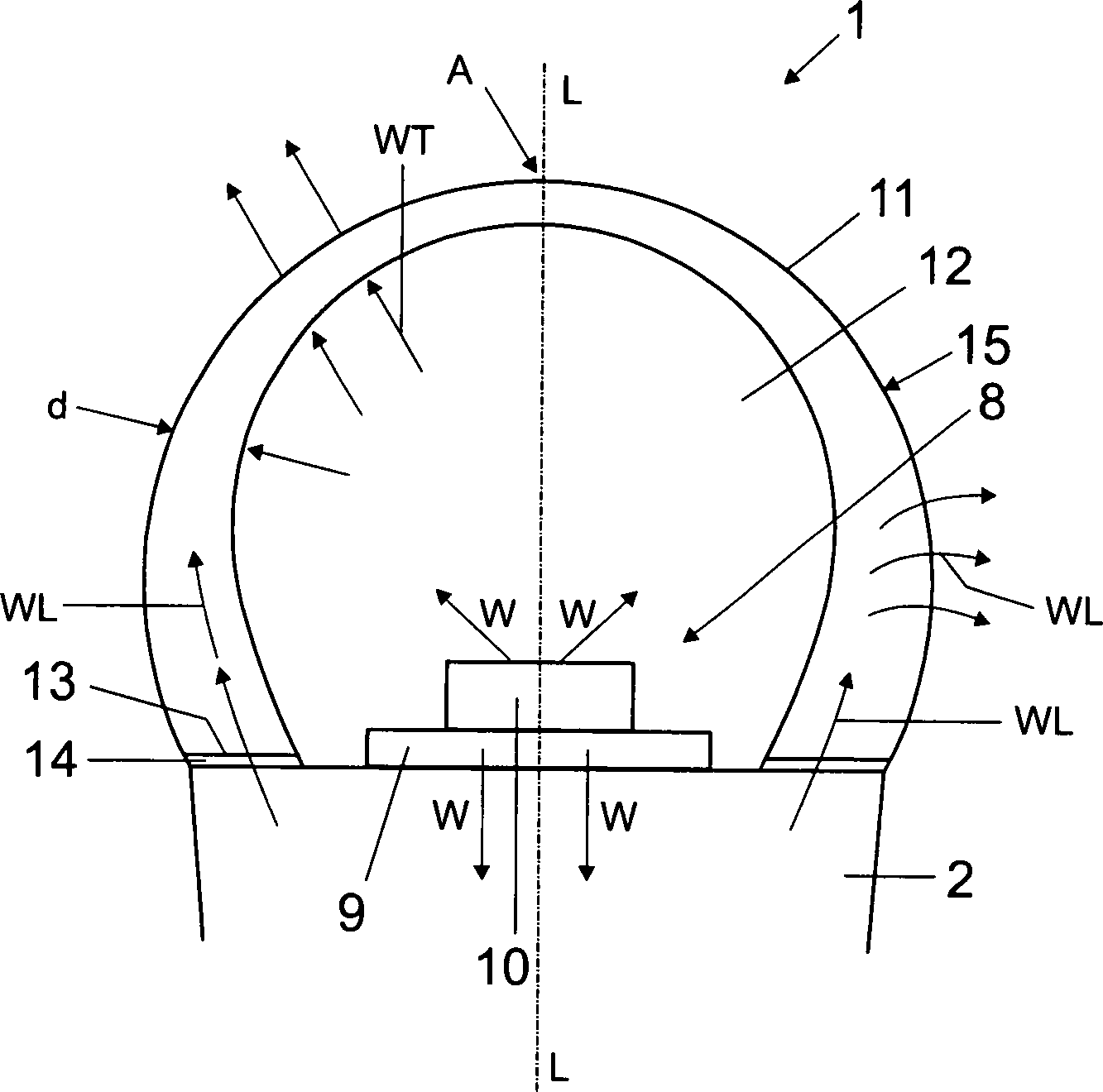
Lampe (1), mindestens aufweisend einen Kühlkörper (2), welcher mindestens eine Lichtquelle (10), insbesondere Halbleiterleuchtelement, speziell Leuchtdiode, trägt, und eine an dem Kühlkörper (2) befestigte, zumindest teilweise lichtdurchlässige Abdeckung (11) für die mindestens eine Lichtquelle (10), wobei die Abdeckung (11) eine Wandstärke (d) aufweist, welche sich zumindest abschnittsweise mit steigender Entfernung von dem Kühlkörper (2) verjüngt.Lamp (1) comprising at least one heat sink (2), which carries at least one light source (10), in particular semiconductor light element, especially light emitting diode, and one on the heat sink (2) fixed, at least partially transparent cover (11) for the at least one Light source (10), wherein the cover (11) has a wall thickness (d), which tapers at least in sections with increasing distance from the heat sink (2).
Description
Die Erfindung betrifft eine Lampe, welche einen Kühlkörper aufweist, der mindestens eine Lichtquelle, insbesondere mindestens ein Halbleiterleuchtelement, trägt, als auch eine an dem Kühlkörper befestigte Abdeckung.The The invention relates to a lamp comprising a heat sink comprising at least one light source, in particular at least a semiconductor light element, carries, as well as one on the Heat sink attached cover.
Generell weisen Leuchtdioden (LEDs) bei höheren Temperaturen geringere Helligkeiten und geringere Lebensdauern auf. Bei LED-Retrofitlampen wird zur Wärmeabfuhr bzw. Kühlung der LED(s) ein Kühlkörper verwendet. Der für den Kühlkörper zur Verfügung stehende Raum ist jedoch begrenzt durch eine meist genormte Außenkontur der zu ersetzenden Lampe und einen Raumbedarf für einen Kolben und eine Treiberelektronik. Durch die räumliche Begrenzung ist die Größe des effektiv zur Kühlung nutzbaren Volumens des Kühlkörpers begrenzt und damit die Kühlleistung. Bei den LED-Lampen mit normbegrenzter Größe wird entsprechend der begrenzten Kühlleistung die Leistung der Lichtquelle und damit die Helligkeit begrenzt.As a general rule LEDs are lower at higher temperatures Brightness and lower lifetimes. For LED retrofit lamps is used for heat dissipation or cooling of the LED (s) Used heatsink. The one for the heat sink however, space available is limited by one usually standardized outer contour of the lamp to be replaced and a space requirement for a piston and a driver electronics. Due to the spatial limit is the size of effectively usable for cooling volume of the heat sink limited and thus the cooling capacity. For the LED lamps with standard size will be according to the limited cooling power the power of the light source and so that the brightness is limited.
Es ist die Aufgabe der vorliegenden Erfindung, mit einfachen Mitteln eine Verbesserung einer Wärmeabfuhr einer Lampe insbesondere der eingangs genannten Art bereitzustellen.It is the object of the present invention, by simple means an improvement of heat dissipation of a lamp in particular to provide the type mentioned.
Diese Aufgabe wird gemäß den Merkmalen der unabhängigen Ansprüche gelöst. Bevorzugte Ausführungsformen sind insbesondere den abhängigen Ansprüchen entnehmbar.These Task is performed according to the characteristics of the independent Claims solved. Preferred embodiments are in particular the dependent claims removable.
Die Aufgabe wird gelöst durch eine Lampe, welche mindestens aufweist: einen Kühlkörper, welcher mindestens eine Lichtquelle trägt, und eine an dem Kühlkörper befestigte, zumindest teilweise lichtdurchlässige (transparente oder transluzente bzw. opake) Abdeckung bzw. Abdeckelement für die mindestens eine Lichtquelle, insbesondere Halbleiterleuchtelement, wobei die Abdeckung eine Wandstärke aufweist, welche sich zumindest abschnittsweise mit steigender Entfernung von dem Kühlkörper verjüngt. In anderen Worten weist die Abdeckung eine Wandstärke auf, welche sich zumindest abschnittsweise mit zunehmender Nähe (geringerem Abstand) zu dem Kühlkörper vergrößert.The Task is solved by a lamp, which at least comprising: a heat sink, which at least carries a light source, and one on the heat sink attached, at least partially translucent (transparent or translucent or opaque) cover or cover element for the at least one light source, in particular semiconductor light element, wherein the cover has a wall thickness which is at least in sections, with increasing distance from the heat sink rejuvenated. In other words, the cover has a wall thickness on, which at least partially with increasing proximity (closer distance) to the heat sink increases.
Durch die vergleichsweise große Wandstärke im Bereich des Kühlkörpers wird eine entsprechend große Kontaktfläche zwischen der Abdeckung und dem Kühlkörper erzeugt. Dadurch wird ein stärkerer Wärmeübergang vom Kühlkörper in das Abdeckelement hinein ermöglicht als es ohne die verbreiterte Wandstärke möglich ist. Folglich wird die Abdeckung stärker aufgeheizt und gibt mehr Wärme an die Umgebung ab. In anderen Worten ermöglicht die verbreiterte (thermische) Kontaktfläche einen höheren Wärmeverlust über die Abdeckung. Eine dicke Wandstärke in einer größeren Entfernung von dem Kühlkörper bzw. der Kontaktfläche ergibt keinen signifikant gesteigerten Kühleffekt aufgrund des sich in der Abdeckung lateral bzw. flächig verteilenden (lateral gerichteten) Wärmeflusses mehr, da durch die Wärmeabgabe an die Umgebung (Entwärmung) mit größerer Entfernung von der Kontaktfläche immer weniger Wärme durch die direkte laterale Wärmeleitung ankommt.By the comparatively large wall thickness in the area the heat sink will be a correspondingly large Contact surface between the cover and the heat sink generated. This will increase the heat transfer allows the heat sink in the cover into it as it is possible without the widened wall thickness is. Consequently, the cover is heated more and gives off more heat to the environment. In other words, the widened (thermal) contact surface a higher Heat loss through the cover. A thick wall thickness at a greater distance from the heat sink or the contact surface does not significantly increase Cooling effect due to in the cover laterally or areal distributing (laterally directed) heat flow more, because of the heat transfer to the environment (heat dissipation) with greater distance from the contact surface less and less heat due to the direct lateral heat conduction arrives.
Aufgrund der Entwärmung über die Abdeckung bzw. deren Oberfläche kann eine bessere Kühlung der Lichtquellen erreicht werden, ohne dass sich die Größe der Lampe verändert. Hiermit können ohne eine wesentliche Vergrößerung der Abmessungen der Lampe größere Verlustleitungen abgeführt werden.by virtue of the heat dissipation through the cover or its surface a better cooling of the light sources can be achieved without changing the size of the lamp. This can be done without a significant increase the dimensions of the lamp larger power loss lines be dissipated.
Allgemein ist die Art der Lichtquelle nicht beschränkt. Es wird jedoch bevorzugt, wenn die mindestens eine Lichtquelle mindestens eine Halbleiterlichtquelle umfasst, z. B. eine Leuchtdiode oder einen Diodenlaser. Besonders bevorzugt ist dabei die Verwendung mindestens einer Leuchtdiode als der mindestens einen Lichtquelle. Dabei ist die Art der mindestens einen Leuchtdiode nicht beschränkt, sondern kann z. B. mehrere Einzel-LEDs oder ein oder mehrere LED-Cluster aus auf einem gemeinsamen Substrat aufgebrachten LED-Chips umfassen. Die Farbe(n) der mindestens einen Leuchtdiode ist ebenfalls nicht beschränkt und kann beispielsweise 'weiß' beinhalten. Die mindestens eine Leuchtdiode kann eine anorganische oder eine organische Leuchtdiode sein. Die Lichtquellen können allgemein mit nachgeschalteten Optiken ausgerüstet sein.Generally The type of light source is not limited. It will, however preferred if the at least one light source at least one Semiconductor light source includes, for. B. a light emitting diode or a diode laser. Particularly preferred is the use of at least one light emitting diode as the at least one light source. It is the type of at least a light-emitting diode is not limited, but z. B. multiple single LEDs or one or more LED clusters on one common LED substrate applied chips. The color (s) the at least one light emitting diode is also not limited and may include, for example, 'white'. The least a light emitting diode may be an inorganic or an organic light emitting diode. The light sources can generally be connected downstream Optics be equipped.
Es ist eine Ausgestaltung, dass die Abdeckung eine größte Wandstärke an einer Kontaktfläche zu dem Kühlkörper aufweist. Dadurch wird eine besonders hohe Wärmeableitung von dem Kühlkörper in die Abdeckung ermöglicht.It is an embodiment that the cover a largest Wall thickness at a contact surface to the heat sink having. This results in a particularly high heat dissipation allows the heat sink in the cover.
Es ist eine weitere Ausgestaltung, dass sich die Wandstärke der Abdeckung mit steigender Entfernung von dem Kühlkörper kontinuierlich verjüngt. Eine kontinuierliche Verringerung der Wandstärke der Abdeckung mit zunehmendem Abstand von dem Kühlkörper bzw. der Kontaktfläche zu dem Kühlkörper bewirkt, dass ein guter Kompromiss zwischen lateraler und transversaler Wärmeleitung in bzw. durch die Abdeckung in den verschiedenen Bereichen von der Abdeckung realisierbar ist.It is a further embodiment that the wall thickness of the cover continuously tapers with increasing distance from the heat sink. A continuous reduction in wall thickness the cover with increasing distance from the heat sink or the contact surface to the heat sink causes a good compromise between lateral and transverse heat conduction in or through the cover in the different areas of the cover is feasible.
Es ist eine alternative Ausgestaltung, dass die Wandstärke der Abdeckung sich abschnittsweise mit steigender Entfernung von der Kontaktfläche zu dem Kühlkörper verjüngt und anschließend daran die Wandstärke der Abdeckung im Wesentlichen konstant bleibt.It is an alternative embodiment that the wall thickness the cover sections with increasing distance from the contact surface tapers to the heat sink and then the wall thickness of the cover remains essentially constant.
Eine geringe Wandstärke der Abdeckung in einem Bereich entfernt von dem Kühlkörper, insbesondere in der größten Entfernung von dem Kühlkörper, ist vorteilhaft, da dort eine Entwärmung an die Umgebungsluft größtenteils durch einen transversalen Wärmefluss aus einem aufgeheizten Innenraum oder Aufnahmeraum erzeugt wird und nicht durch den lateralen Wärmefluss von dem Kühlkörper. Der transversale Wärmefluss ist um so effektiver, je geringer die Wandstärke der Abdeckung ist. Eine geringe Wandstärke der Abdeckung ist auch aus optischer Sicht vorteilhaft, da eine Transmission mit abnehmender Wandstärke der Abdeckung zunimmt und damit zumindest die abgestrahlte Helligkeit in einem geringeren Maße gedämpft wird.A small wall thickness of the cover in a range removed from the heat sink, especially in the largest one Removal from the heat sink is advantageous since there is a cooling to the ambient air for the most part by a transverse heat flow from a heated Interior or receiving space is generated and not by the lateral Heat flow from the heat sink. The transversal Heat flow is the more effective, the smaller the wall thickness the cover is. A small wall thickness of the cover is also advantageous from an optical point of view, since a transmission with decreasing wall thickness of the cover increases and thus at least the radiated brightness to a lesser extent is dampened.
Es ist noch eine Ausgestaltung, dass die Abdeckung an dem Kühlkörper mittels mindestens eines gut wärmeleitenden Haftmittels befestigt ist. Die Verwendung des Haftmittels weist den Vorteil auf, dass die Verbindung bzw. die Kontaktflächen zwischen dem Kühlkörper und der Abdeckung geometrisch einfach ausgestaltbar ist, insbesondere ist die Verbindung an planen Kontaktflächen möglich.It Another embodiment is that the cover on the heat sink by means of at least one good heat-conducting adhesive is attached. The use of the adhesive has the advantage on that the connection or the contact surfaces between the heat sink and the cover geometrically simple is ausgestaltbar, in particular, the connection to flat contact surfaces possible.
Das Haftmittel kann ein thermisch gut leitendes Haftmittel sein, z. B. eine Wärmeleitpaste, ein Wärmeleitkleber oder mindestens ein Wärmeleitpad. Allgemein sollte der Effekt des Haftmittels auf eine Wärmedurchleitung minimiert werden. Jedoch ist die Erfindung nicht auf die Auswahl eines thermisch gut leitenden Haftmittels beschränkt. So ist bei einer geringen Dicke des Haftmittels, z. B. einer dünnen Klebeschicht, ein Einfluss des Wärmeleitfähigkeitskoeffizienten des Haftmittels auf einen Wärmefluss durch das Haftmittel bei ausreichend großer Kontaktfläche für die meisten Haftmittel gering.The Adhesive may be a thermally conductive adhesive, for. As a thermal paste, a thermal adhesive or at least one thermal pad. Generally, the effect should be of the adhesive to a heat transmission can be minimized. However, the invention is not limited to the selection of a thermally highly conductive Adhesive limited. So is at a small thickness of the adhesive, for. As a thin adhesive layer, an influence the thermal conductivity coefficient of the adhesive to a heat flow through the adhesive at sufficient great contact area for most Adhesive low.
Alternativ kann die Abdeckung auch mittels mechanischer Verbindungsmittel an dem Kühlkörper angebracht sein, z. B. mittels einer Steckverbindung oder einer Klammer- oder Klemmverbindung usw. Dabei kann auch ein geringer Luftspalt zwischen dem Kühlkörper und der Abdeckung vorhanden sein. Ist dieser Luftspalt schmal genug, kann bei ausreichend großer Kontaktfläche auch eine signifikante Wärmeübertragung durch den Luftspalt hindurch erfolgen. Die Kontaktfläche der Abdeckung ist dann eine rein thermische Kontaktfläche oder Wärmeübergangsfläche.alternative The cover can also by means of mechanical fasteners be attached to the heat sink, z. B. by means a connector or a clamp or clamp connection, etc. Here can also have a small air gap between the heat sink and the cover be present. Is this air gap narrow enough, can with sufficient contact surface too a significant heat transfer through the air gap through. The contact surface of the cover is then a purely thermal contact surface or heat transfer surface.
Alternativ kann die Abdeckung auch in den Kühlkörper eingeschraubt sein, wobei die Abdeckung z. B. an ihrer Kontaktfläche mit dem Kühlkörper eine Schraubenform und der Kühlkörper eine passende Gewindeform aufweisen kann. Dies erhöht die Kontaktfläche zwischen der Abdeckung und dem Kühlkörper weiter.alternative The cover can also be screwed into the heat sink be, with the cover z. B. at their contact surface with the heat sink a helical shape and the Heatsink have a matching thread shape can. This increases the contact area between the Cover and the heat sink on.
Das Material der Abdeckung braucht grundsätzlich nicht besonders nach seiner Wärmeleitfähigkeit ausgesucht zu sein. So kann für die Abdeckung ein üblicher Kunststoff oder Glas verwendet werden, z. B. ein herkömmliches Lampenkolbenmaterial. Jedoch wird ein gut wärmeleitendes Material bevorzugt. Eine gute Wärmeleitung verbessert eine laterale Wärmeverteilung in der Abdeckung, wodurch sich eine effektive Kühlungsfläche innerhalb der Abdeckung vergrößert und die Wärme stärker an die Umgebung abgegeben werden kann. Gleichzeitig verbessert die gute Wärmeleitung eine transversale Wärmeleitung von einem durch die Abdeckung umgebenen Innenraum durch die Abdeckung hindurch.The Material of the cover basically does not need much to be selected according to its thermal conductivity. So can for the cover a common plastic or glass are used, for. B. a conventional lamp envelope material. However, a good heat conductive material is preferred. A good heat conduction improves lateral heat distribution in the cover, resulting in an effective cooling surface inside the cover increases and the heat can be given more to the environment. simultaneously improves the good heat conduction a transverse heat conduction from an inner space surrounded by the cover through the cover therethrough.
Es ist zudem eine Ausgestaltung, dass die Abdeckung aus Glas besteht. Die Verwendung von Glas weist den Vorteil auf, dass Glas vergleichsweise preiswert, einfärbbar, gut formbar und alterungsbeständig ist. Glas kann ferner einfach aufgeraut oder auf andere Art diffus streuend ausgestaltet sein, um die Lichtquelle von außen nicht direkt sichtbar zu machen.It is also an embodiment that the cover is made of glass. The use of glass has the advantage that glass is comparatively inexpensive, Dyeable, easy to shape and resistant to aging is. Glass can also simply be roughened or otherwise diffused be diffused to the light source from the outside not directly visible.
Es ist eine spezielle Ausgestaltung, dass die Abdeckung beispielsweise eine Wärmeleitfähigkeit zwischen 1 W/(m·K) und 2 W/(m·K) aufweist. Insbesondere wird ein thermisch leitfähiges Glas mit einem Wärmeleitfähigkeitskoeffizienten λ von ca. 1,2 W/(m·K) oder mehr bevorzugt. Während übliche Gläser, wie Fensterglas, einen Wärmeleitfähigkeitskoeffizienten λ zwischen 0,8 und 1,0 W/(m·K) aufweisen, weist z. B. Borofloatglas ein λ von ca. 1,2 W/(m·K) auf, N-BK10 ein λ von ca. 1,32 W/(m·K) und Zerodur ein λ von ca. 1,46 W/(m·K). Durch die vergleichsweise hohe thermische Leitfähigkeit wird eine großflächige Wärmeverteilung in der Abdeckung und damit eine effiziente Wärmeabfuhr über die äußere Oberfläche der Abdeckung erreicht.It is a special design that covers for example a thermal conductivity between 1 W / (m · K) and 2 W / (m · K). In particular, a thermal conductive glass with a thermal conductivity coefficient λ of about 1.2 W / (m · K) or more preferably. While usual Glasses, such as window glass, a coefficient of thermal conductivity λ between 0.8 and 1.0 W / (m · K), z. B. borofloate glass a λ of about 1.2 W / (m · K) on, N-BK10 a λ of about 1.32 W / (m · K) and Zerodur a λ of about 1.46 W / (m · K). Due to the comparatively high thermal conductivity becomes a large-scale heat distribution in the cover and thus efficient heat dissipation over reaches the outer surface of the cover.
Alternativ ist beispielsweise auch die Verwendung eines lichtdurchlässigen Kunststoffs (z. B. Polycarbonat) oder einer lichtdurchlässigen Keramik (z. B. einer Aluminiumoxid-Keramik) möglich. So kann eine lichtdurchlässige Keramik einen Wärmeleitfähigkeitskoeffizienten λ von 30 W/(m·K) oder mehr erreichen. Als ein Kunststoff kann beispielsweise ein mit einem hoch thermisch leitfähigen Material verfüllter Kunststoff verwendet werden.Alternatively, for example, it is also possible to use a translucent plastic (for example polycarbonate) or a translucent ceramic (for example an aluminum oxide ceramic). Thus, a translucent ceramic can achieve a thermal conductivity coefficient λ of 30 W / (m · K) or more. As a plastic can beispielswei se be used with a highly thermally conductive material filled plastic.
Es ist außerdem eine Ausgestaltung, dass die Abdeckung eine domartige Form aufweist. Eine solche Abdeckung ist beispielsweise für eine Retrofit-Glühlampe besonders geeignet.It is also an embodiment that the cover a has a dome-like shape. Such a cover is for example particularly suitable for a retrofit bulb.
Die Abdeckung kann alternativ eine offene oder eine geschlossene Röhrenform aufweist. Eine solche Abdeckung ist beispielsweise für eine Retrofit-Leuchtstoffröhre oder eine Retrofit-Linienlampe (z. B. vom Typ Linestra der Fa. Osram) geeignet.The Cover may alternatively have an open or a closed tubular shape having. Such a cover is for example a retrofit fluorescent tube or a retrofit line lamp (eg of the Linestra type from Osram).
Es ist eine spezielle Ausgestaltung, dass eine (insbesondere thermische) Kontaktfläche der Abdeckung zu dem Kühlkörper einer (unteren) Auflagefläche der Abdeckung zumindest teilweise entspricht. Bei der domartigen Form und der offenen Röhrenform stellt die Kontaktfläche der Abdeckung gleichzeitig die Auflagefläche der Abdeckung auf dem Kühlkörper dar und damit üblicherweise deren tiefsten Punkt. Dabei kann sich insbesondere die Wandstärke mit steigender Entfernung von der Kontaktfläche bzw. mit steigender Höhe verringern, insbesondere kontinuierlich verringern. Der höchste Punkt, die Apsis, weist somit die geringste Wandstärke auf.It is a special configuration that one (especially thermal) Contact surface of the cover to the heat sink a (lower) bearing surface of the cover at least partially equivalent. At dome-shaped and open tubular form represents the contact surface of the cover at the same time Support surface of the cover on the heat sink and thus usually their lowest point. there In particular, the wall thickness may increase with increasing distance from the contact surface or with increasing height reduce, in particular reduce continuously. The highest point, the apse, thus has the lowest wall thickness.
Es ist eine alternative Ausgestaltung, dass die Abdeckung eine scheibenartige Form aufweist. Dadurch ist die Abdeckung insbesondere für eine PAR(Parabolic Aluminized Reflector)-Scheinwerfer-Retrofitlampe oder Leuchte bzw. für dessen Leuchtmittel geeignet. Die Abdeckung ist insbesondere auch für Lampen oder Retrofitlampen vom Typ MR16 geeignet, alternativ auch für andere MR-Lampenformen, z. B. MR11 oder MR8.It is an alternative embodiment that the cover is a disc-like Form has. This makes the cover especially for a PAR (Parabolic Aluminized Reflector) headlight retrofit lamp or luminaire or suitable for its illuminant. The Cover is especially suitable for lamps or retrofit lamps suitable for MR16 type, alternatively also for other MR lamp shapes, z. MR11 or MR8.
Es ist dann eine weitere spezielle Ausgestaltung, dass eine Kontaktfläche der Abdeckung zu dem Kühlkörper seitlich angeordnet ist. Bei der scheibenartigen Form stellt die Kontaktfläche der Abdeckung gleichzeitig die seitliche Anlagefläche der Abdeckung (welche meist dem Seitenrand der Abdeckung entspricht) auf dem Kühlkörper dar und damit üblicherweise deren äußersten Punkt. Dabei kann sich insbesondere die Wandstärke mit steigender Entfernung von der Kontaktfläche verringern. Der innerste Punkt der Abdeckung, insbesondere deren Mittelpunkt, weist somit die geringste Wandstärke auf.It is then another special design that a contact surface the cover to the heat sink arranged laterally is. In the disc-like shape, the contact surface the cover at the same time the lateral contact surface of the Cover (which usually corresponds to the side edge of the cover) on the heat sink and thus usually their extreme point. This can in particular the wall thickness with increasing distance from the contact surface reduce. The innermost point of the cover, especially its Center, thus has the lowest wall thickness.
Es ist eine weitere Ausgestaltung, dass die Abdeckung eine optische Funktion aufweist. Dies hat den Vorteil, dass gleichzeitig eine Strahlführung oder Strahlkorrektur ermöglicht wird.It Another embodiment is that the cover has an optical Function has. This has the advantage that at the same time a Beam guidance or beam correction allows becomes.
Es ist eine dazu alternative Ausgestaltung, dass die Abdeckung eine im Wesentlichen optisch nicht aktive Abdeckung ist, also im Wesentlichen zum Schutz der Lampe dient.It is an alternative embodiment that the cover a is essentially optically inactive cover, so essentially serves to protect the lamp.
Es ist eine weitere Ausgestaltung, dass die mindestens eine Lichtquelle, insbesondere Halbleiterleuchtelement, über mindestens ein Substrat auf dem Kühlkörper befestigt ist. Das Substrat kann beispielsweise ein Substrat eines LED-Clusters, d. h. ein gemeinsames Substrat für mehrere LED-Chips, sein. Das Substrat kann zusätzlich oder alternativ mindestens eine Leiterplatte umfassen, z. B. zur Kontaktierung des LED-Clusters oder mindestens einer Einzel-LED (LED-Modul) und ggf. zur Bestückung mit elektronischen Bauelementen.It is a further embodiment that the at least one light source, in particular semiconductor element, via at least one Substrate is mounted on the heat sink. The Substrate, for example, a substrate of an LED cluster, d. H. a common substrate for multiple LED chips, his. The Substrate may additionally or alternatively at least one Circuit board include, for. B. for contacting the LED cluster or at least one single LED (LED module) and possibly for equipping with electronic components.
Es kann eine weitere Ausgestaltung sein, dass die Abdeckung eine zumindest mantelseitig geschlossene Röhrenform aufweist und der Kühlkörper zumindest teilweise von der Abdeckung aufgenommen ist und zumindest teilweise an einem unteren Bereich der Abdeckung befestigt ist, wobei der untere Bereich der Abdeckung und ein oberer Bereich der Abdeckung eine vergleichsweise geringere Wandstärke aufweisen als die beiden seitlichen Bereiche der Abdeckung.It may be another embodiment that the cover at least one shell-side closed tubular shape and the heat sink at least partially received by the cover and at least partially is attached to a lower portion of the cover, wherein the lower portion of the cover and an upper portion of the cover have a comparatively smaller wall thickness than the two lateral areas of the cover.
Es ist eine weitere vorteilhafte Ausgestaltung, dass die Abdeckung an ihrer Innenseite im Wesentlichen frei von Hinterschnitten ist, also im Wesentlichen keinen Hinterschnitt aufweist. Dadurch ist die Möglichkeit einer Fertigung im Spritzgussverfahren (bei Kunststoff) oder im Pressverfahren (bei Glas oder Keramikmaterial) gegeben. Die Innenseite der Abdeckung begrenzt den Innenraum der Lampe.It is a further advantageous embodiment that the cover is substantially free of undercuts on its inside, So essentially has no undercut. This is the result Possibility of production by injection molding (at Plastic) or in the pressing process (with glass or ceramic material) given. The inside of the cover limits the interior of the Lamp.
Es kann eine spezielle Ausgestaltung sein, dass die Abdeckung an ihrer Innenseite zumindest seitlich im Wesentlichen gerade Konturen aufweist. Dies vereinfacht eine Fertigung im Spritzgussverfahren oder im Pressverfahren besonders.It may be a special design that the cover on her Inner side has at least laterally substantially straight contours. This simplifies production by injection molding or pressing especially.
Es ist noch eine Ausgestaltung, dass die Lampe eine Retrofit-Lampe ist, deren Außenkontur nicht oder nicht Wesentlich über eine Außenkontur einer zu ersetzenden Lampe hinausgeht.It Another design is that the lamp is a retrofit lamp is whose outer contour is not or not essential about an outer contour of a lamp to be replaced goes out.
Insbesondere zur Verwendung mit einer Glühlampen-Retrofitlampe ist es vorteilhaft, dass die Abdeckung in ihren äußeren Abmessungen der Kontur, insbesondere Rundung, der zu ersetzenden Glühlampe folgt. Dies gilt vorzugsweise analog Retrofitlampen zum Ersatz einer Lampe herkömmlichen Typs, z. B. einer Linienlampe, Reflektorlampe usw.Especially it is for use with an incandescent retrofit lamp advantageous that the cover in their outer Dimensions of the contour, in particular rounding, of the bulb to be replaced follows. This preferably applies analogously retrofit lamps to replace a Lamp of conventional type, for. B. a line lamp, reflector lamp etc.
Die
Erfindung kann insbesondere ein oder mehrere der folgenden Merkmale
umfassen:
Eine Lampe, insbesondere eine LED-Lampe, weist einen
Sockel, einen Kühlkörper, ein LED-Modul und eine
semitransparente oder transparente Abdeckung, z. B. einen Lampenkolben
bzw. eine semitransparente oder transparente Optik oder Abdeckscheibe
auf.In particular, the invention may comprise one or more of the following features:
A lamp, in particular an LED lamp, has a base, a heat sink, an LED module and a semi-transparent or transparent cover, for. B. a lamp bulb or a semi-transparent or transparent optics or cover disc.
Die Abdeckung (z. B. der Kolben/die Optik/die Abdeckscheibe) ist vorzugsweise zum Kühlkörper hin dicker ausgeführt und weist eine breitflächige Anbindungsfläche bzw. Kontaktfläche zur thermischen Anbindung an den Kühlkörper auf.The Cover (eg, the piston / optic / cover) is preferred made thicker towards the heat sink and has a broad area connection surface or contact surface for thermal connection to the heat sink on.
Die Abdeckung ist über die Kontaktfläche vorzugsweise mittels eines gut wärmeleitfähigen Haftmittels, z. B. einer Paste, eines Klebers und/oder eines Pads usw. an den Kühlkörper angebunden. Das Haftmittel kann insbesondere ein TIM (Thermal Interface Material) sein.The Cover is preferably over the contact surface by means of a good thermal conductivity adhesive, z. As a paste, an adhesive and / or a pad, etc. to the Heatsink connected. The adhesive may in particular a TIM (Thermal Interface Material).
Die Abdeckung wird vorzugsweise mit zunehmendem Abstand von der Kühlkörperkontaktfläche dünner.The Cover is preferably with increasing distance from the heat sink contact surface thinner.
In den folgenden Figuren wird die Erfindung anhand von Ausführungsbeispielen schematisch genauer beschrieben. Dabei können zur Übersichtlichkeit gleiche oder gleichwirkende Elemente mit gleichen Bezugszeichen versehen sein.In The following figures illustrate the invention with reference to exemplary embodiments described in more detail schematically. It can for clarity identical or equivalent elements with the same reference numerals be provided.
Auf
einer Oberseite
An
der Oberseite
Der
Kleber
Die
Abdeckung
Die
Abdeckung
Die
Abdeckung
Die
Abdeckung
Die
Funktion der Abdeckung
Ein
Teil der Wärme W des Kühlkörpers
Aufgrund
des aufgeheizten Aufnahmeraums
An
und kurz hinter der Kontaktfläche
Durch
die relative Verbreiterung der Wandstärke d zu der Kontaktfläche
Andererseits
wird durch die relative Verringerung der Wandstärke d mit
zunehmender Entfernung von der Kontaktfläche
Für
eine Glühlampen-Retrofitlampe
In
diesem Ausführungsbeispiel entspricht die Kontaktfläche
In
einer dem Ausführungsbeispiel aus
Am
Mittelpunkt M ist der relative Einfluss des lateral gerichteten
Wärmeflusses WL am geringsten und folglich derjenige des
transversal gerichteten Wärmeflusses WT am größten,
so dass für eine effektive Wärmeabfuhr von der
Abdeckung
Die
Retrofitlampe
Auf
der Oberseite
In
diesem Fall weisen seitliche Scheitelpunkte S die größte
Wandstärke d auf, während ein oberer Scheitelpunkt
A1 und ein unterer Scheitelpunkt A2 die geringste Wandstärke
d aufweisen. Dabei wird vorausgesetzt, dass das LED-Modul
In
anderen Worten weist die Abdeckung
Insbesondere ändert
sich die Wandstärke d der Abdeckung
Eine
solche Form der Abdeckung
Die
Abdeckung
Während
in dem oberen Bereich I der transversal gerichtete Wärmestrom
WT dominiert, hat es sich gezeigt, dass auch an dem unteren Bereich
II eine geringe Wandstärke d vorteilhaft ist, da dort eine direkte
Wärmeableitung von dem Kühlkörper
Die
Wandstärke d ist an der Kontaktfläche
Alternativ
kann sich der Abschnitt
Die
Abdeckung
Die
Wandstärke d ist an der Kontaktfläche
Alternativ
kann sich der Abschnitt
Folglich
ist die Wandstärke d nicht mehr an der Kontaktfläche
Selbstverständlich ist die vorliegende Erfindung nicht auf die gezeigten Ausführungsbeispiele beschränkt.Of course the present invention is not limited to the embodiments shown.
So braucht ferner die Abdeckung der mantelseitig geschlossenen röhrenförmigen Abdeckung nicht bezüglich einer Längsachse symmetrisch ausgebildet zu sein.So also needs the cover of the shell side closed tubular Cover not symmetrical with respect to a longitudinal axis to be educated.
Der Unterschied der Wandstärke d zwischen der dicksten Stelle der Abdeckung und der dünnsten Stelle der Abdeckung kann allgemein bevorzugt einen Faktor zwischen zwei und fünf annehmen.The difference in wall thickness d between the thickest point of the cover and the thinnest The location of the cover may generally preferably take a factor between two and five.
BezugszeichenlisteLIST OF REFERENCE NUMBERS
- 11
- Glühlampen-RetrofitlampeIncandescent retrofit lamp
- 22
- Kühlkörperheatsink
- 33
- Mantelfläche des Kühlkörperslateral surface of the heat sink
- 44
- Kühlrippecooling fin
- 55
- Unterseite des Kühlkörpersbottom of the heat sink
- 66
- Sockelbase
- 77
- Oberseite des Kühlkörperstop of the heat sink
- 88th
- LED-ModulLED module
- 99
- Leiterplattecircuit board
- 1010
- Leuchtdiodeled
- 1111
- Abdeckungcover
- 1212
- Aufnahmeraumaccommodation space
- 1313
- Kontaktflächecontact area
- 1414
- Klebeschichtadhesive layer
- 1515
- Außenseite der Abdeckungoutside the cover
- 1616
- Retrofitlamperetrofit
- 1717
- Kühlkörperheatsink
- 1818
- Öffnung des Kühlkörpersopening of the heat sink
- 1919
- Abdeckungcover
- 2020
- Retrofitlamperetrofit
- 2121
- Kühlkörperheatsink
- 2222
- Basis des KühlkörpersBase of the heat sink
- 2323
- Abdeckungcover
- 2424
- Retrofitlamperetrofit
- 2525
- Kühlkörperheatsink
- 2626
- Abdeckungcover
- 2727
- Kontaktflächecontact area
- 2828
- Innenseite der Abdeckunginside the cover
- 2929
- Außenseite der Abdeckungoutside the cover
- 3030
- Retrofitlamperetrofit
- 3131
- Abdeckungcover
- 3232
- Innenseiteinside
- 3333
- seitliche Fläche der Innenseitelateral Surface of the inside
- 3434
- Deckenfläche der Innenseiteceiling surface the inside
- 3535
- Abschnitt der Abdeckungsection the cover
- 3636
- Abschnitt der Abdeckungsection the cover
- 3737
- Retrofitlamperetrofit
- 3838
- Abdeckungcover
- 3939
- Retrofitlamperetrofit
- 4040
- Abdeckungcover
- AA
- Apsisapse
- A1A1
- oberer Scheitelpunktupper vertex
- A2A2
- unterer Scheitelpunktlower vertex
- II
- unterer Bereichlower Area
- IIII
- oberer Bereichupper Area
- IIIIII
- seitlicher Bereichlateral Area
- LL
- Längsachselongitudinal axis
- MM
- MittelpunktFocus
- SS
- seitlicher Scheitelpunktlateral vertex
- WLWL
- lateral gerichteter Wärmeflusslaterally directed heat flow
- WTWT
- transversal gerichteter Wärmeflusstransversal directed heat flow
ZITATE ENTHALTEN IN DER BESCHREIBUNGQUOTES INCLUDE IN THE DESCRIPTION
Diese Liste der vom Anmelder aufgeführten Dokumente wurde automatisiert erzeugt und ist ausschließlich zur besseren Information des Lesers aufgenommen. Die Liste ist nicht Bestandteil der deutschen Patent- bzw. Gebrauchsmusteranmeldung. Das DPMA übernimmt keinerlei Haftung für etwaige Fehler oder Auslassungen.This list The documents listed by the applicant have been automated generated and is solely for better information recorded by the reader. The list is not part of the German Patent or utility model application. The DPMA takes over no liability for any errors or omissions.
Zitierte PatentliteraturCited patent literature
- - US 2007/0080362 A1 [0003] US 2007/0080362 A1 [0003]
Claims (15)
Priority Applications (8)
| Application Number | Priority Date | Filing Date | Title |
|---|---|---|---|
| DE102009035370A DE102009035370A1 (en) | 2009-07-30 | 2009-07-30 | lamp |
| CA2769496A CA2769496A1 (en) | 2009-07-30 | 2010-07-20 | Lamp |
| JP2012522104A JP2013500560A (en) | 2009-07-30 | 2010-07-20 | lamp |
| EP10739320.9A EP2459925B1 (en) | 2009-07-30 | 2010-07-20 | Light bulb |
| AU2010277788A AU2010277788A1 (en) | 2009-07-30 | 2010-07-20 | Light bulb |
| CN201080033951.9A CN102472434B (en) | 2009-07-30 | 2010-07-20 | lamp |
| US13/388,031 US8851716B2 (en) | 2009-07-30 | 2010-07-20 | Lamp incorporating a heat sink and an optically transmissive cover |
| PCT/EP2010/060475 WO2011012498A1 (en) | 2009-07-30 | 2010-07-20 | Light bulb |
Applications Claiming Priority (1)
| Application Number | Priority Date | Filing Date | Title |
|---|---|---|---|
| DE102009035370A DE102009035370A1 (en) | 2009-07-30 | 2009-07-30 | lamp |
Publications (1)
| Publication Number | Publication Date |
|---|---|
| DE102009035370A1 true DE102009035370A1 (en) | 2011-02-03 |
Family
ID=42797609
Family Applications (1)
| Application Number | Title | Priority Date | Filing Date |
|---|---|---|---|
| DE102009035370A Ceased DE102009035370A1 (en) | 2009-07-30 | 2009-07-30 | lamp |
Country Status (8)
| Country | Link |
|---|---|
| US (1) | US8851716B2 (en) |
| EP (1) | EP2459925B1 (en) |
| JP (1) | JP2013500560A (en) |
| CN (1) | CN102472434B (en) |
| AU (1) | AU2010277788A1 (en) |
| CA (1) | CA2769496A1 (en) |
| DE (1) | DE102009035370A1 (en) |
| WO (1) | WO2011012498A1 (en) |
Cited By (7)
| Publication number | Priority date | Publication date | Assignee | Title |
|---|---|---|---|---|
| DE102011003968A1 (en) * | 2011-02-11 | 2012-08-16 | Osram Ag | A semiconductor light emitting device and method for mounting a cover to a holder of a semiconductor light emitting device |
| WO2013011408A1 (en) * | 2011-07-15 | 2013-01-24 | Koninklijke Philips Electronics N.V. | Illumination device with carrier and envelope |
| WO2013009542A3 (en) * | 2011-07-13 | 2013-04-25 | Cree, Inc. | Variable thickness globe |
| WO2013119568A1 (en) * | 2012-02-06 | 2013-08-15 | Xicato, Inc. | Led-based light source with hybrid spot and general lighting characteristics |
| DE102012203902A1 (en) * | 2012-03-13 | 2013-09-19 | Trilux Gmbh & Co. Kg | OLED cooling element |
| DE202012102963U1 (en) * | 2012-08-07 | 2013-11-13 | Rp-Technik E.K. | Fluorescent lamp-like LED bulb |
| EP3569446A1 (en) * | 2018-05-16 | 2019-11-20 | Christoph Pavani | Decorative strip |
Families Citing this family (15)
| Publication number | Priority date | Publication date | Assignee | Title |
|---|---|---|---|---|
| US10125931B2 (en) * | 2008-03-01 | 2018-11-13 | Goldeneye, Inc. | Barrier with integrated self cooling solid state light sources |
| JP5042375B1 (en) * | 2011-05-10 | 2012-10-03 | シャープ株式会社 | Straight tube lamp |
| US8746915B2 (en) * | 2011-07-29 | 2014-06-10 | Cree, Inc. | Light emitting die (LED) lamps, heat sinks and related methods |
| US20140160762A1 (en) * | 2012-12-07 | 2014-06-12 | GE Lighting Solutions, LLC | Diffuser element and lighting device comprised thereof |
| CN103032785A (en) * | 2012-12-20 | 2013-04-10 | 苏州东山精密制造股份有限公司 | LED (Light-Emitting Diode) ceiling lamp |
| JP6387971B2 (en) | 2013-02-19 | 2018-09-12 | フィリップス ライティング ホールディング ビー ヴィ | Lighting device with improved thermal properties |
| CA2938027A1 (en) * | 2014-01-27 | 2015-07-30 | Shanghai Sansi Electronic Engineering Co., Ltd | Led lighting device |
| CN103791439B (en) * | 2014-01-27 | 2015-05-06 | 上海三思电子工程有限公司 | Novel LED lighting device |
| CN106662295B (en) | 2014-07-21 | 2020-07-14 | 昕诺飞控股有限公司 | Lighting device with virtual light source |
| JP6453660B2 (en) | 2015-02-05 | 2019-01-16 | 株式会社東芝 | Lighting device |
| CN105987352A (en) * | 2015-03-05 | 2016-10-05 | 深圳市裕富照明有限公司 | Optical light-diffusing part and light-emitting device |
| JP2016181441A (en) * | 2015-03-24 | 2016-10-13 | アイリスオーヤマ株式会社 | Luminaire |
| CN107366836A (en) * | 2017-06-28 | 2017-11-21 | 太仓市普利照明电器有限公司 | A kind of dual-purpose insulation illuminating lamp |
| US10845013B2 (en) | 2018-10-03 | 2020-11-24 | Vista Manufacturing Inc | Flexible light assembly |
| JP7580063B2 (en) * | 2020-08-24 | 2024-11-11 | パナソニックIpマネジメント株式会社 | Light source unit and lighting fixture |
Citations (5)
| Publication number | Priority date | Publication date | Assignee | Title |
|---|---|---|---|---|
| EP1298383A2 (en) * | 2001-09-28 | 2003-04-02 | Osram Sylvania Inc. | Replaceable led lamp capsule |
| DE202006018835U1 (en) * | 2006-12-13 | 2007-03-08 | Patent-Treuhand-Gesellschaft für elektrische Glühlampen mbH | LED-Light e.g. for outside lightening systems, has closed housing where LED is installed on plate and has outwardly arranged inlets |
| US20070080362A1 (en) | 2005-10-07 | 2007-04-12 | Osram Sylvania Inc. | LED with light transmissive heat sink |
| DE202008007862U1 (en) * | 2008-06-12 | 2008-08-21 | Lin, Hsiang-Chou | LED light with freestanding cooling fins |
| DE102007040596A1 (en) * | 2007-08-27 | 2009-03-05 | Epsys Paul Voinea E.K. | Lamp, for doctors and dentists, has a LED with a heat-conductive filling material and lacquer between the lamp and the base plate and filling the drillings for the electrical connections |
Family Cites Families (24)
| Publication number | Priority date | Publication date | Assignee | Title |
|---|---|---|---|---|
| JP2002314136A (en) * | 2001-04-09 | 2002-10-25 | Toyoda Gosei Co Ltd | Semiconductor light emitting device |
| JP2003281925A (en) * | 2002-01-16 | 2003-10-03 | Meiji Univ | Lighting fixture, lighting fixture body and LED element |
| JP4235427B2 (en) * | 2002-09-24 | 2009-03-11 | オスラム・メルコ株式会社 | Light emitting diode lamp |
| US20050068777A1 (en) * | 2003-09-25 | 2005-03-31 | Dragoslav Popovic | Modular LED light and method |
| US6908219B1 (en) * | 2004-03-29 | 2005-06-21 | Valeo Sylvania Llc | Optical element for a high mounted stop lamp with an LED light source |
| KR100638611B1 (en) * | 2004-08-12 | 2006-10-26 | 삼성전기주식회사 | Multi Lens Light Emitting Diode |
| TWI261654B (en) * | 2004-12-29 | 2006-09-11 | Ind Tech Res Inst | Lens and LED with uniform light emitted applying the lens |
| JP4899502B2 (en) * | 2005-03-07 | 2012-03-21 | 日亜化学工業株式会社 | Surface irradiation light source and surface irradiation device |
| CN100585268C (en) * | 2005-03-07 | 2010-01-27 | 日亚化学工业株式会社 | Planar irradiation light source and planar irradiation device |
| KR101136344B1 (en) * | 2005-04-06 | 2012-04-18 | 삼성전자주식회사 | Optical lens, optical module having the optical lens, back light assembly having the optical module and display apparatus having the back light assembly |
| NL1029583C2 (en) | 2005-07-21 | 2007-01-25 | Imt B V | Explosion-proof fixture. |
| US7378686B2 (en) * | 2005-10-18 | 2008-05-27 | Goldeneye, Inc. | Light emitting diode and side emitting lens |
| JP4013077B2 (en) * | 2005-11-21 | 2007-11-28 | 松下電工株式会社 | Light emitting device and manufacturing method thereof |
| JP2007194132A (en) * | 2006-01-20 | 2007-08-02 | Fujifilm Holdings Corp | Lighting device |
| JP2007207576A (en) * | 2006-02-01 | 2007-08-16 | Jefcom Kk | LED lamp |
| JP4565656B2 (en) * | 2006-02-28 | 2010-10-20 | スタンレー電気株式会社 | Lamp |
| JP2008059862A (en) * | 2006-08-30 | 2008-03-13 | Ichikoh Ind Ltd | Vehicle lighting |
| DE202007008258U1 (en) * | 2007-04-30 | 2007-10-31 | Lumitech Produktion Und Entwicklung Gmbh | LED bulbs |
| KR101289069B1 (en) * | 2007-05-09 | 2013-07-22 | 엘지디스플레이 주식회사 | Light emitting diode package having structure of dual lens and liquid crystal display device thereby |
| KR100809658B1 (en) | 2007-06-27 | 2008-03-05 | 김재을 | LED lens and LED display device using same |
| DE202008017219U1 (en) * | 2008-08-05 | 2009-04-16 | Pyroswift Holding Co., Ltd., Wanchai | LED light unit |
| JP4334013B1 (en) * | 2008-09-29 | 2009-09-16 | 株式会社サンエスオプテック | LED lighting device |
| US8360604B2 (en) * | 2009-09-30 | 2013-01-29 | Cree, Inc. | Light emitting diode (LED) lighting systems including low absorption, controlled reflectance enclosures |
| CN201582724U (en) * | 2009-12-18 | 2010-09-15 | 重庆三弓科技发展有限公司 | Led lampshade |
-
2009
- 2009-07-30 DE DE102009035370A patent/DE102009035370A1/en not_active Ceased
-
2010
- 2010-07-20 JP JP2012522104A patent/JP2013500560A/en active Pending
- 2010-07-20 EP EP10739320.9A patent/EP2459925B1/en active Active
- 2010-07-20 CN CN201080033951.9A patent/CN102472434B/en active Active
- 2010-07-20 CA CA2769496A patent/CA2769496A1/en not_active Abandoned
- 2010-07-20 WO PCT/EP2010/060475 patent/WO2011012498A1/en not_active Ceased
- 2010-07-20 AU AU2010277788A patent/AU2010277788A1/en not_active Abandoned
- 2010-07-20 US US13/388,031 patent/US8851716B2/en active Active
Patent Citations (5)
| Publication number | Priority date | Publication date | Assignee | Title |
|---|---|---|---|---|
| EP1298383A2 (en) * | 2001-09-28 | 2003-04-02 | Osram Sylvania Inc. | Replaceable led lamp capsule |
| US20070080362A1 (en) | 2005-10-07 | 2007-04-12 | Osram Sylvania Inc. | LED with light transmissive heat sink |
| DE202006018835U1 (en) * | 2006-12-13 | 2007-03-08 | Patent-Treuhand-Gesellschaft für elektrische Glühlampen mbH | LED-Light e.g. for outside lightening systems, has closed housing where LED is installed on plate and has outwardly arranged inlets |
| DE102007040596A1 (en) * | 2007-08-27 | 2009-03-05 | Epsys Paul Voinea E.K. | Lamp, for doctors and dentists, has a LED with a heat-conductive filling material and lacquer between the lamp and the base plate and filling the drillings for the electrical connections |
| DE202008007862U1 (en) * | 2008-06-12 | 2008-08-21 | Lin, Hsiang-Chou | LED light with freestanding cooling fins |
Cited By (13)
| Publication number | Priority date | Publication date | Assignee | Title |
|---|---|---|---|---|
| WO2012107298A3 (en) * | 2011-02-11 | 2012-11-15 | Osram Ag | Semiconductor lighting device and method for installing a cover on a mounting of a semiconductor lighting device |
| DE102011003968A1 (en) * | 2011-02-11 | 2012-08-16 | Osram Ag | A semiconductor light emitting device and method for mounting a cover to a holder of a semiconductor light emitting device |
| WO2013009542A3 (en) * | 2011-07-13 | 2013-04-25 | Cree, Inc. | Variable thickness globe |
| US9506622B2 (en) | 2011-07-15 | 2016-11-29 | Koninklijke Philips Electronics N.V. | Illumination device with carrier and envelope |
| CN103703308A (en) * | 2011-07-15 | 2014-04-02 | 皇家飞利浦有限公司 | Illumination device with carrier and envelope |
| WO2013011408A1 (en) * | 2011-07-15 | 2013-01-24 | Koninklijke Philips Electronics N.V. | Illumination device with carrier and envelope |
| CN103703308B (en) * | 2011-07-15 | 2017-04-12 | 飞利浦照明控股有限公司 | Illumination device with carrier and envelope |
| RU2624455C2 (en) * | 2011-07-15 | 2017-07-04 | Филипс Лайтинг Холдинг Б.В. | Lighting device with holder and bulb |
| WO2013119568A1 (en) * | 2012-02-06 | 2013-08-15 | Xicato, Inc. | Led-based light source with hybrid spot and general lighting characteristics |
| US8820951B2 (en) | 2012-02-06 | 2014-09-02 | Xicato, Inc. | LED-based light source with hybrid spot and general lighting characteristics |
| DE102012203902A1 (en) * | 2012-03-13 | 2013-09-19 | Trilux Gmbh & Co. Kg | OLED cooling element |
| DE202012102963U1 (en) * | 2012-08-07 | 2013-11-13 | Rp-Technik E.K. | Fluorescent lamp-like LED bulb |
| EP3569446A1 (en) * | 2018-05-16 | 2019-11-20 | Christoph Pavani | Decorative strip |
Also Published As
| Publication number | Publication date |
|---|---|
| CN102472434A (en) | 2012-05-23 |
| US20120163001A1 (en) | 2012-06-28 |
| CN102472434B (en) | 2016-12-28 |
| US8851716B2 (en) | 2014-10-07 |
| EP2459925A1 (en) | 2012-06-06 |
| AU2010277788A1 (en) | 2012-02-23 |
| JP2013500560A (en) | 2013-01-07 |
| EP2459925B1 (en) | 2018-04-11 |
| CA2769496A1 (en) | 2011-02-03 |
| WO2011012498A1 (en) | 2011-02-03 |
Similar Documents
| Publication | Publication Date | Title |
|---|---|---|
| EP2459925B1 (en) | Light bulb | |
| DE102010043921B4 (en) | Lighting device and method for producing a lighting device | |
| DE102009022723A1 (en) | Rear-mounted LED module for combination rear lights on motor vehicles | |
| WO2011054716A2 (en) | Lighting device comprising a bulb | |
| DE102014202759A1 (en) | Semiconductor tube lamp | |
| EP2499420A1 (en) | Illumination device | |
| DE102012220455A1 (en) | LIGHTING DEVICE WITH SEMICONDUCTOR LIGHT SOURCE | |
| DE102010030296B4 (en) | Lamp with concave reflector and a projection for at least one light source | |
| DE102016210636A1 (en) | Optics for a headlight, optics arrangement and headlights | |
| EP2297515B1 (en) | Retaining frame having at least one optical element | |
| DE10250383A1 (en) | LED arrangement with reflector | |
| DE102012206397A1 (en) | Lighting device with reflector and aperture | |
| DE102009021353A1 (en) | Headlight for use as front lighting for motorbike, has rotary paraboloid shape reflector composed of multiple reflector elements, and light sources arranged centered in reflector and arranged on separate cooing surfaces | |
| DE102011007214B4 (en) | Piston for semiconductor light-emitting device and semiconductor light-emitting device | |
| DE10044455A1 (en) | Signal light has focusing element with individual reflectors, each associated with light body e.g. LED or light emitting semiconducting bodies in matrix layout with reflectors | |
| DE102009023055A1 (en) | Line bulb-retrofit lamp has semiconductor lighting element having light emitting diode, radiator box and band-shaped semiconductor lighting module, which has semiconductor shining element and which is fastened on radiator box | |
| DE202009014892U1 (en) | illuminant | |
| DE102017222649A1 (en) | LIGHT MODULE, ARRANGEMENT, HEADLIGHTS AND METHOD | |
| WO2010133631A1 (en) | Heat sink for an illumination device | |
| DE102009044388A1 (en) | Outdoor light and high pressure lamp replacement | |
| EP1840455B1 (en) | Vehicle lighting unit with at least two light sources | |
| EP2564116B1 (en) | Led luminaire as a replacement for incandescent light bulbs | |
| WO2012136578A1 (en) | Led lamp comprising an led as the luminaire and a glass or plastic lampshade | |
| WO2011124399A1 (en) | Led lamp | |
| DE102015208569A1 (en) | Lamp with LEDs |
Legal Events
| Date | Code | Title | Description |
|---|---|---|---|
| OP8 | Request for examination as to paragraph 44 patent law | ||
| R081 | Change of applicant/patentee |
Owner name: OSRAM GMBH, DE Free format text: FORMER OWNER: OSRAM GESELLSCHAFT MIT BESCHRAENKTER HAFTUNG, 81543 MUENCHEN, DE Effective date: 20111207 Owner name: LEDVANCE GMBH, DE Free format text: FORMER OWNER: OSRAM GESELLSCHAFT MIT BESCHRAENKTER HAFTUNG, 81543 MUENCHEN, DE Effective date: 20111207 |
|
| R081 | Change of applicant/patentee |
Owner name: LEDVANCE GMBH, DE Free format text: FORMER OWNER: OSRAM AG, 81543 MUENCHEN, DE Effective date: 20121119 Owner name: OSRAM GMBH, DE Free format text: FORMER OWNER: OSRAM AG, 81543 MUENCHEN, DE Effective date: 20121119 |
|
| R081 | Change of applicant/patentee |
Owner name: OSRAM GMBH, DE Free format text: FORMER OWNER: OSRAM GMBH, 81543 MUENCHEN, DE Effective date: 20130822 Owner name: LEDVANCE GMBH, DE Free format text: FORMER OWNER: OSRAM GMBH, 81543 MUENCHEN, DE Effective date: 20130822 |
|
| R081 | Change of applicant/patentee |
Owner name: LEDVANCE GMBH, DE Free format text: FORMER OWNER: OSRAM GMBH, 80807 MUENCHEN, DE |
|
| R082 | Change of representative |
Representative=s name: DF-MP DOERRIES FRANK-MOLNIA & POHLMAN PATENTAN, DE |
|
| R002 | Refusal decision in examination/registration proceedings | ||
| R003 | Refusal decision now final |