DE102009019140B4 - Method for calibrating a position measuring device and method for measuring a mask - Google Patents
Method for calibrating a position measuring device and method for measuring a mask Download PDFInfo
- Publication number
- DE102009019140B4 DE102009019140B4 DE102009019140.2A DE102009019140A DE102009019140B4 DE 102009019140 B4 DE102009019140 B4 DE 102009019140B4 DE 102009019140 A DE102009019140 A DE 102009019140A DE 102009019140 B4 DE102009019140 B4 DE 102009019140B4
- Authority
- DE
- Germany
- Prior art keywords
- mask
- structures
- diffractive structures
- calibration
- measuring
- Prior art date
- Legal status (The legal status is an assumption and is not a legal conclusion. Google has not performed a legal analysis and makes no representation as to the accuracy of the status listed.)
- Active
Links
Images


Classifications
-
- G—PHYSICS
- G03—PHOTOGRAPHY; CINEMATOGRAPHY; ANALOGOUS TECHNIQUES USING WAVES OTHER THAN OPTICAL WAVES; ELECTROGRAPHY; HOLOGRAPHY
- G03F—PHOTOMECHANICAL PRODUCTION OF TEXTURED OR PATTERNED SURFACES, e.g. FOR PRINTING, FOR PROCESSING OF SEMICONDUCTOR DEVICES; MATERIALS THEREFOR; ORIGINALS THEREFOR; APPARATUS SPECIALLY ADAPTED THEREFOR
- G03F9/00—Registration or positioning of originals, masks, frames, photographic sheets or textured or patterned surfaces, e.g. automatically
- G03F9/70—Registration or positioning of originals, masks, frames, photographic sheets or textured or patterned surfaces, e.g. automatically for microlithography
- G03F9/7003—Alignment type or strategy, e.g. leveling, global alignment
- G03F9/7019—Calibration
-
- G—PHYSICS
- G03—PHOTOGRAPHY; CINEMATOGRAPHY; ANALOGOUS TECHNIQUES USING WAVES OTHER THAN OPTICAL WAVES; ELECTROGRAPHY; HOLOGRAPHY
- G03F—PHOTOMECHANICAL PRODUCTION OF TEXTURED OR PATTERNED SURFACES, e.g. FOR PRINTING, FOR PROCESSING OF SEMICONDUCTOR DEVICES; MATERIALS THEREFOR; ORIGINALS THEREFOR; APPARATUS SPECIALLY ADAPTED THEREFOR
- G03F1/00—Originals for photomechanical production of textured or patterned surfaces, e.g., masks, photo-masks, reticles; Mask blanks or pellicles therefor; Containers specially adapted therefor; Preparation thereof
- G03F1/38—Masks having auxiliary features, e.g. special coatings or marks for alignment or testing; Preparation thereof
- G03F1/42—Alignment or registration features, e.g. alignment marks on the mask substrates
-
- G—PHYSICS
- G03—PHOTOGRAPHY; CINEMATOGRAPHY; ANALOGOUS TECHNIQUES USING WAVES OTHER THAN OPTICAL WAVES; ELECTROGRAPHY; HOLOGRAPHY
- G03F—PHOTOMECHANICAL PRODUCTION OF TEXTURED OR PATTERNED SURFACES, e.g. FOR PRINTING, FOR PROCESSING OF SEMICONDUCTOR DEVICES; MATERIALS THEREFOR; ORIGINALS THEREFOR; APPARATUS SPECIALLY ADAPTED THEREFOR
- G03F7/00—Photomechanical, e.g. photolithographic, production of textured or patterned surfaces, e.g. printing surfaces; Materials therefor, e.g. comprising photoresists; Apparatus specially adapted therefor
- G03F7/70—Microphotolithographic exposure; Apparatus therefor
- G03F7/70483—Information management; Active and passive control; Testing; Wafer monitoring, e.g. pattern monitoring
- G03F7/70491—Information management, e.g. software; Active and passive control, e.g. details of controlling exposure processes or exposure tool monitoring processes
- G03F7/70516—Calibration of components of the microlithographic apparatus, e.g. light sources, addressable masks or detectors
-
- G—PHYSICS
- G03—PHOTOGRAPHY; CINEMATOGRAPHY; ANALOGOUS TECHNIQUES USING WAVES OTHER THAN OPTICAL WAVES; ELECTROGRAPHY; HOLOGRAPHY
- G03F—PHOTOMECHANICAL PRODUCTION OF TEXTURED OR PATTERNED SURFACES, e.g. FOR PRINTING, FOR PROCESSING OF SEMICONDUCTOR DEVICES; MATERIALS THEREFOR; ORIGINALS THEREFOR; APPARATUS SPECIALLY ADAPTED THEREFOR
- G03F9/00—Registration or positioning of originals, masks, frames, photographic sheets or textured or patterned surfaces, e.g. automatically
- G03F9/70—Registration or positioning of originals, masks, frames, photographic sheets or textured or patterned surfaces, e.g. automatically for microlithography
- G03F9/7003—Alignment type or strategy, e.g. leveling, global alignment
- G03F9/7007—Alignment other than original with workpiece
- G03F9/7011—Pre-exposure scan; original with original holder alignment; Prealignment, i.e. workpiece with workpiece holder
Landscapes
- Physics & Mathematics (AREA)
- General Physics & Mathematics (AREA)
- Exposure And Positioning Against Photoresist Photosensitive Materials (AREA)
- Length Measuring Devices By Optical Means (AREA)
Abstract
Verfahren zum Kalibrieren einer Vorrichtung (10) zur Positionsvermessung von Messstrukturen (14) auf einer Lithographiemaske (12), wobei die Vorrichtung (10) eine Aufnahmeeinrichtung (20) sowie einen verschiebbaren Maskenhalter (16) aufweist, mit den Schritten:
– Qualifizieren einer Kalibriermaske (40) mit darauf angeordneten diffraktiven Strukturen (42) durch Bestimmen von Positionen der diffraktiven Strukturen (42) zueinander mittels interferometrischer Messung,
– Bestimmen von Positionen von auf der Kalibriermaske (40) angeordneten Messstrukturen (14) zueinander mittels der Vorrichtung (10), indem die einzelnen Messstrukturen (14) durch entsprechendes Verschieben des Maskenhalters (16) nacheinander im Zentrum des Bildfeldes der Aufnahmeeinrichtung (20) angeordnet werden, sowie
– Kalibrieren der Vorrichtung (10) mittels der für die Messstrukturen (14) bestimmten Positionen sowie der für die diffraktiven Strukturen (42) bestimmten Positionen.Method for calibrating a device (10) for measuring the position of measuring structures (14) on a lithographic mask (12), wherein the device (10) has a receiving device (20) and a displaceable mask holder (16), with the steps:
Qualifying a calibration mask (40) with diffractive structures (42) arranged thereon by determining positions of the diffractive structures (42) relative to one another by means of interferometric measurement,
- Determining positions of on the calibration mask (40) arranged measuring structures (14) to each other by means of the device (10) by the individual measuring structures (14) by corresponding displacement of the mask holder (16) successively in the center of the image field of the receiving device (20) be, as well
Calibrating the device (10) by means of the positions determined for the measuring structures (14) and the positions determined for the diffractive structures (42).
Description
Hintergrund der ErfindungBackground of the invention
Die Erfindung betrifft ein Verfahren zum Kalibrieren einer Vorrichtung zur Positionsvermessung von Messstrukturen auf einer Lithographiemaske, nachstehend auch als Positionsmessvorrichtung bezeichnet, sowie ein Verfahren zum Vermessen einer Maske für die Mikrolithographie.The invention relates to a method for calibrating a device for measuring the position of measuring structures on a lithography mask, hereinafter also referred to as position measuring device, and a method for measuring a mask for microlithography.
Die hochgenaue Positionsvermessung von Messstrukturen, wie etwa Justagemarken, auch „Alignment-Marken” bezeichnet, auf einer Lithographiemaske gehört zu den zentralen Aufgaben der Maskenmetrologie. Sie wird auch als Photomaskenstrukturplazierung oder „Photomask Pattern Placement” (PPPM) bezeichnet. Über die Vermessung der Messstrukturen wird die Maßverkörperung auf der Maske mit einer hohen Genauigkeit generiert. Sie ist eine unabdingbare Voraussetzung dafür, im Schreibprozess der Masken mit Elektronenstrahlschreibern die Positionsgenauigkeit der Strukturen auf der Maske überhaupt zu ermöglichen. Weiterhin ermöglicht die Vermessung der Messstrukturen eines bestehenden Maskensatzes, die Abweichung der Strukturpositionen der verschiedenen Masken für die einzelnen lithographischen Schichten zueinander zu qualifizieren. Diese Abweichung der Strukturpositionen von Maske zu Maske wird auch als „Overlay” bezeichnet. Masken im oben genannten Sinne werden oft auch als Retikel bezeichnet.The highly accurate position measurement of measuring structures, such as alignment marks, also referred to as "alignment marks", on a lithographic mask is one of the central tasks of mask metrology. It is also referred to as photomask pattern placement or photomask pattern placement (PPPM). By measuring the measuring structures, the material measure on the mask is generated with high accuracy. It is an indispensable prerequisite for enabling the positional accuracy of the structures on the mask in the writing process of the masks with electron beam writers. Furthermore, the measurement of the measurement structures of an existing mask set makes it possible to qualify the deviation of the structure positions of the different masks for the individual lithographic layers from one another. This deviation of the structure positions from mask to mask is also referred to as "overlay". Masks in the above sense are often referred to as reticles.
Mit der Verkleinerung der Maskenstrukturen von Technologieknoten zu Technologieknoten nehmen auch die Anforderungen an die Positionsvermessung der Maskenstrukturen stetig zu. Durch Technologien wie Doppelstrukturierung erhöhen sich die Anforderungen an das Masken-zu-Masken-Overlay und damit an die Strukturpositionierung darüber hinaus deutlich. Da die einzelnen Masken eines Maskensatzes in zunehmendem Maße in verschiedenen, oft weltweit verteilten Maskenhäusern hergestellt und mit unterschiedlichen Positionsmessvorrichtungen, welche auch als „Registration-Anlagen” bezeichnet werden, vermessen werden, kommt der Abstimmung der einzelnen Positionsmessvorrichtungen zueinander eine immer größer werdende Bedeutung zu.With the reduction of the mask structures from technology nodes to technology nodes, the requirements for the position measurement of the mask structures are also steadily increasing. Technologies such as double structuring significantly increase the requirements for the mask-to-mask overlay and thus for the structure positioning. Since the individual masks of a mask set are increasingly produced in different, often globally distributed mask houses and measured with different position measuring devices, which are also referred to as "registration systems", the coordination of the individual position measuring devices to each other is becoming increasingly important.
Die Positionsbestimmung auf Lithographiemasken beruht herkömmlicherweise ausschließlich auf einer interferometrischen Längenmessung. Hierzu werden Justagemarken einer Maske einzeln mittels eines mikroskopischen Bildes hinsichtlich ihrer Position erfasst. Über einen Positioniertisch werden die einzelnen Justagemarken der Maske nacheinander in das Zentrum des Bildfeldes gefahren und die Position der jeweiligen Justagemarke über Kantenschwellwerte oder über Korrelationsmethoden bestimmt. Daraufhin wird der Abstand zur vorher vermessenen Justagemarke durch Bestimmung des vom Positioniertisch zwischen den Messungen zurückgelegten Weges bestimmt. Der vom Positioniertisch zurückgelegte Weg wird mittels längeninterferometrischer Messung ermittelt.The position determination on lithography masks conventionally relies exclusively on an interferometric length measurement. For this purpose, alignment marks of a mask are recorded individually by means of a microscopic image with respect to their position. Via a positioning table, the individual alignment marks of the mask are moved one after the other into the center of the image field and the position of the respective alignment mark is determined via edge threshold values or via correlation methods. Then the distance to the previously measured alignment mark is determined by determining the path traveled by the positioning table between the measurements. The path traveled by the positioning table is determined by means of length interferometric measurement.
Die Kalibrierung von Positionsmessvorrichtungen erfolgt herkömmlicherweise durch Selbstkonsistenztests. Dabei wird eine Kalibriermaske in unterschiedlichen Einlegepositionen und Drehstellungen vermessen. Aus dem quasi-redundanten Messdatensatz lassen sich Positionsfehler der Justagemarken auf der Kalibriermaske von immanenten Fehlern der Positionsmessvorrichtung separieren. Letztere werden wiederum zur Kalibrierung der Positionsmessvorrichtung verwendet.The calibration of position measuring devices is conventionally carried out by self-consistency tests. A calibration mask is measured in different insertion positions and rotational positions. From the quasi-redundant measurement data set, position errors of the adjustment marks on the calibration mask can be separated from inherent errors of the position measuring device. The latter are in turn used to calibrate the position measuring device.
Typische Ursachen für Fehler der Positionsmessvorrichtung sind u. a. Interferometerfehler sowie Kipp- und Unebenheiten der Interferometerspiegel. Solche Fehler können zwar durch oben beschriebene Kalibrierverfahren berücksichtigt werden, dennoch bleiben solche Methoden an die Messung an der Positionsmessvorrichtung selbst gebunden. Dies führt insbesondere zu den nachstehend aufgeführten Problemen.Typical causes of errors of the position measuring device are u. a. Interferometer errors as well as tilting and unevenness of the interferometer mirror. Although such errors can be accounted for by the above-described calibration methods, such methods remain bound to the measurement at the position measuring device itself. This leads in particular to the problems listed below.
Jedes Kalibrierverfahren auf der vorgenannten Basis ist blind für spezielle ihm eigene Fehlertypen. So lassen sich spezielle Klassen von Fehlern durch eine einfache Kalibriermessung nicht erfassen und abseparieren. Beispiele für die Ursachen derartiger Fehler sind u. a.: Spiegelunebenheiten mit Ortsfrequenzen größer als das Kalibrierraster, das sich aus den verschiedenen Einlegepositionen ergibt, Fehllagen der Maske, Bildfeldrotation, Unebenheiten der Maske, etc.Each calibration procedure on the basis mentioned above is blind to special types of errors inherent in it. Thus, special classes of errors can not be detected and separated by a simple calibration measurement. Examples of the causes of such errors are u. a .: mirror unevenness with spatial frequencies greater than the calibration grid, which results from the different insertion positions, misplacements of the mask, image field rotation, unevenness of the mask, etc.
Diesem Problem wird herkömmlicherweise dadurch begegnet, dass die Redundanz der Messungen erhöht wird. Dies erhöht jedoch den Messaufwand deutlich. Der Messaufwand für die Kalibrierung steigt damit mit den Genauigkeitsanforderungen und der Kalibriergüte.This problem is conventionally addressed by increasing the redundancy of the measurements. However, this significantly increases the measurement effort. The measurement effort for the calibration thus increases with the accuracy requirements and the calibration quality.
Durch Anpassung der einzelnen Positionsmessvorrichtungen gleichen Typs aneinander können Ausfälle einzelner Maschinen registriert werden. Systematische Fehler, die verfahrensinhärent sind und dem Maschinentyp innewohnen, werden jedoch nicht erkannt.By adapting the individual position measuring devices of the same type to each other, failures of individual machines can be registered. Systematic errors that are inherent in the process and inherent in the machine type, however, are not recognized.
Die Druckschrift
Zugrunde liegende Aufgabe Underlying task
Es ist die Aufgabe der Erfindung, die vorgenannten Probleme zu lösen und insbesondere ein Kalibrierverfahren bereitzustellen, womit eine Vorrichtung zur Positionsvermessung von Messstrukturen auf einer Lithographiemaske mit verbesserter Genauigkeit kalibriert werden kann.It is the object of the invention to solve the abovementioned problems and in particular to provide a calibration method, with which a device for position measurement of measurement structures on a lithography mask can be calibrated with improved accuracy.
Erfindungsgemäße LösungInventive solution
Gemäß der Erfindung wird ein Verfahren zum Kalibrieren einer Vorrichtung zur Positionsvermessung von Messstrukturen auf einer Lithographiemaske gemäß Anspruch 1 bereitgestellt. Eine Kalibriermaske im Sinne dieser Anmeldung muss nicht exklusiv der Kalibrierung der Vorrichtung dienen. Wie nachstehend näher erläutert, kann gemäß einer Ausführungsform auch eine mit entsprechenden diffraktiven Strukturen versehene Produktmaske bzw. Nutzmaske als Kalibriermaske dienen. Gemäß einer anderen Ausführungsform dient die Kalibriermaske lediglich der Kalibrierung der Vorrichtung und umfasst keine auf einen Wafer abzubildende Produktstrukturen.According to the invention, a method for calibrating a device for position measurement of measurement structures on a lithography mask according to
Als Messstrukturen im Sinne dieser Anmeldung können eigene Justagemarken oder auch auf einen Wafer abzubildende Nutzstrukturen bzw. Produktstrukturen dienen. In einer Ausführungsform können die Messstrukturen auch als sogenannte „in-die-Strukturen” auf der Lithographiemaske enthalten sein.As measurement structures in the sense of this application, own adjustment marks or useful structures or product structures to be imaged onto a wafer can be used. In one embodiment, the measurement structures may also be contained as so-called "in-the-structures" on the lithography mask.
Mit anderen Worten wird erfindungsgemäß ein Kalibrierverfahren zum Kalibrieren einer sogenannten „Registration-Anlage” bereitgestellt. Eine derartige „Registration-Anlage” dient der Positionsvermessung von Messstrukturen auf einer Maske für die Mikrolithographie, d. h. einer Maske, welche dafür vorgesehen ist, in einer Projektionsbelichtungsanlage für die Mikrolithographie auf einen Halbleiter-Wafer abgebildet zu werden. In einem ersten Schritt des erfindungsgemäßen Kalibrierverfahrens wird eine Kalibriermaske mit darauf angeordneten diffraktiven Strukturen bereitgestellt. Die diffraktiven Strukturen sind derart gestaltet, dass durch interferometrische Vermessung der diffraktiven Strukturen die Positionen derselben ermittelt werden können. Der Abstand zwischen den diffraktiven Strukturen kann sehr klein sein oder sogar null werden, so dass die einzelnen diffraktiven Strukturen ineinander übergehen.In other words, a calibration method for calibrating a so-called "registration system" is provided according to the invention. Such a "registration system" serves the position measurement of measurement structures on a mask for microlithography, d. H. a mask which is intended to be imaged onto a semiconductor wafer in a microlithographic projection exposure apparatus. In a first step of the calibration method according to the invention, a calibration mask with diffractive structures arranged thereon is provided. The diffractive structures are designed such that the positions of the same can be determined by interferometric measurement of the diffractive structures. The distance between the diffractive structures can be very small or even zero, so that the individual diffractive structures merge into one another.
Nach einer derartigen interferometrischen Bestimmung der Positionen der diffraktiven Strukturen zueinander werden die Positionen von auf der Kalibriermaske angeordneten Messstrukturen mittels der Positionsmessvorrichtung bestimmt. Die Messstrukturen können zusätzlich zu den diffraktiven Strukturen auf der Kalibriermaske angeordnet sein. Alternativ können auch die diffraktiven Strukturen selbst als Messstrukturen fungieren. Der mittels der interferometrischen Messung erzeugte Positionsdatensatz sowie der mittels der Positionsmessvorrichtung ermittelte Positionsdatensatz werden daraufhin verwendet, um die Positionsmessvorrichtung zu kalibrieren.After such an interferometric determination of the positions of the diffractive structures relative to one another, the positions of measuring structures arranged on the calibration mask are determined by means of the position-measuring device. The measurement structures may be arranged on the calibration mask in addition to the diffractive structures. Alternatively, the diffractive structures themselves can function as measuring structures. The position data set generated by means of the interferometric measurement and the position data set determined by means of the position measuring device are then used to calibrate the position measuring device.
Die erfindungsgemäße interferometrische Positionsbestimmung der diffraktiven Strukturen lässt sich damit insbesondere auf eine flächenhafte Positionsmessung auf der Kalibriermaske durch Wellenfrontvermessung zurückführen. Mittels einer derartigen Wellenfrontvermessung kann eine Positionsmessgenauigkeit der diffraktiven Strukturen von besser als 2 nm, insbesondere besser als 1 nm, 0,5 nm oder 0,1 nm erzielt werden. Damit wird durch das erfindungsgemäße Verfahren eine Referenzmethode mit hoher Absolutgenauigkeit zur Verfügung gestellt, zusätzlich beruht das Verfahren auf einem vollkommen unterschiedlichen Messprinzip im Vergleich zur bei herkömmlichen Kalibrierverfahren angewandten Vermessung der Messstrukturen durch Bilderfassung sowie interferometrischer Längenmessung. Die Verwendung einer derartigen andersartigen Messmethode ermöglicht Fehlerseparation, wodurch die Absolutgenauigkeit der Kalibrierung der Positionsmessvorrichtung erhöht werden kann.The inventive interferometric position determination of the diffractive structures can thus be attributed in particular to a planar position measurement on the calibration mask by wavefront measurement. By means of such a wavefront measurement, a positional accuracy of the diffractive structures of better than 2 nm, in particular better than 1 nm, 0.5 nm or 0.1 nm can be achieved. Thus, the method according to the invention provides a reference method with high absolute accuracy; in addition, the method is based on a completely different measuring principle in comparison with the measurement of the measuring structures by image acquisition and interferometric length measurement used in conventional calibration methods. The use of such a different measuring method enables error separation, which can increase the absolute accuracy of the calibration of the position measuring device.
In einer Ausführungsform des Kalibrierverfahrens nach der Erfindung wird beim Qualifizieren der Kalibriermaske eine Messwelle eines Interferometers derart auf die Kalibriermaske eingestrahlt, dass diese in Littrow-Reflexion an den diffraktiven Strukturen reflektiert wird, und die reflektierte Welle wird mit einer Referenzwelle zur Erzeugung eines Interferenzmusters überlagert. Die Messwelle kann als ebene Welle konfiguriert sein. Bei einer Littrow-Reflexion sind die diffraktiven Strukturen in Bezug auf die Messwelle derart ausgerichtet, dass die an den diffraktiven Strukturen unter einer bestimmten Beugungsordnung reflektierte Weile im Strahlengang der eingehenden Messwelle zurückläuft.In one embodiment of the calibration method according to the invention, when qualifying the calibration mask, a measurement wave of an interferometer is irradiated onto the calibration mask such that it is reflected in Littrow reflection at the diffractive structures, and the reflected wave is superimposed with a reference wave to produce an interference pattern. The measuring shaft can be configured as a plane wave. In a Littrow reflection, the diffractive structures are aligned with respect to the measuring wave such that the reflected at the diffractive structures under a certain diffraction order back in the beam path of the incoming measuring wave.
In einer weiteren Ausführungsform nach der Erfindung wird die Kalibriermaske nacheinander in zwei unterschiedlichen Orientierungen in Bezug auf die Messwelle angeordnet, bei denen die Messwelle unter jeweils einer anderen Beugungsordnung an den diffraktiven Strukturen in Littrow-Reflexion reflektiert wird. Insbesondere wird die Kalibriermaske nacheinander derart orientiert, dass die Messwelle jeweils in einer positiven und einer negativen Beugungsordnung in Littrow-Reflexion reflektiert wird, wobei der Betrag der Beugungsordnung jeweils gleich ist. In einer Ausführungsform wird die Kalibriermaske nacheinander derart verkippt, dass die Messwelle in der +1. und der –1. Beugungsordnung Littrowreflektiert wird. Die Positionen der diffraktiven Strukturen werden durch Differenzbildung der interferometrischen Messungen bei den unterschiedlichen Orientierungen bestimmt. Gemäß einer Variante wird daraufhin die Kalibriermaske bezüglich ihrer Oberflächennormale um 90° gedreht und die Messung für beide Kippstellungen wiederholt. Aus den Messungen beider Rotationsstellungen lassen sich die Positionen der diffraktiven Strukturen in zwei orthogonalen Koordinatenrichtungen bestimmen.In a further embodiment according to the invention, the calibration mask is arranged successively in two different orientations with respect to the measuring wave, in which the measuring wave is reflected in each case under a different diffraction order at the diffractive structures in Littrow reflection. In particular, the calibration mask is oriented successively in such a way that the measurement wave is reflected in each case in a positive and a negative diffraction order in Littrow reflection, the magnitude of the diffraction order being the same in each case. In one embodiment, the calibration mask is successively tilted such that the measurement wave in the +1. and the -1. Diffraction order Littrow is reflected. The positions of the diffractive structures are determined by subtraction of the determined interferometric measurements at the different orientations. According to a variant, the calibration mask is then rotated 90 ° with respect to its surface normal and the measurement is repeated for both tilt positions. From the measurements of both rotational positions, the positions of the diffractive structures in two orthogonal coordinate directions can be determined.
In einer weiteren Ausführungsform nach der Erfindung wird eine weitere Kalibriermaske, deren diffraktive Strukturen sich von den diffraktiven Strukturen der ersten Kalibriermaske hinsichtlich ihres Strukturtyps unterscheiden, bereitgestellt. Die Positionen der diffraktiven Strukturen der weiteren Kalibriermaske werden mittels interferometrischer Messung bestimmt. Daraufhin werden aus den für die diffraktiven Strukturen der beiden Kalibriermasken bestimmten Positionen systematische Fehler in Abhängigkeit des Strukturtyps bestimmt und die gemessenen Positionen der ersten Kalibriermaske durch Herausrechnen der durch den Strukturtyp der diffraktiven Strukturen der ersten Kalibriermaske bedingten systematischen Fehler korrigiert. Beim Kalibrieren der Vorrichtung werden die korrigierten Positionen der diffraktiven Strukturen der ersten Kalibriermaske verwendet. Dies ermöglicht es, die Kalibriergenauigkeit weiter zu erhöhen.In a further embodiment according to the invention, a further calibration mask whose diffractive structures differ from the diffractive structures of the first calibration mask with respect to their structure type is provided. The positions of the diffractive structures of the further calibration mask are determined by means of interferometric measurement. Subsequently, from the positions determined for the diffractive structures of the two calibration masks, systematic errors are determined as a function of the structure type and the measured positions of the first calibration mask are corrected by taking out the systematic errors caused by the structure type of the diffractive structures of the first calibration mask. When calibrating the device, the corrected positions of the diffractive structures of the first calibration mask are used. This makes it possible to further increase the calibration accuracy.
In einer Ausführungsform nach der Erfindung unterscheiden sich die diffraktiven Strukturen der ersten Kalibriermaske von den diffraktiven Strukturen der weiteren Kalibriermaske dadurch hinsichtlich ihres Strukturtyps, dass sie sich hinsichtlich ihrer Geometrie und/oder Größe unterscheiden. In einer weiteren Ausführungsform nach der Erfindung wird der strukturelle Unterschied dadurch erzeugt, dass die diffraktiven Strukturen auf der ersten Kalibriermaske mittels eines ersten Herstellungsverfahrens und die diffraktiven Strukturen auf der weiteren Kalibriermaske mittels eines sich davon unterscheidenden zweiten Herstellungsverfahrens erzeugt werden. So können beispielsweise bei dem einem Herstellungsverfahren die diffraktiven Strukturen durch Elektronenstrahlschreiben und bei dem anderen Herstellungsverfahren durch holographische Belichtung erzeugt werden.In an embodiment according to the invention, the diffractive structures of the first calibration mask differ from the diffractive structures of the further calibration mask in terms of their structure type in that they differ in terms of their geometry and / or size. In a further embodiment according to the invention, the structural difference is produced by generating the diffractive structures on the first calibration mask by means of a first manufacturing method and the diffractive structures on the further calibration mask by means of a second manufacturing method different therefrom. For example, in one manufacturing method, the diffractive structures may be generated by electron beam writing and in the other manufacturing method by holographic exposure.
In einer weiteren Ausführungsform nach der Erfindung werden die Messstrukturen von den diffraktiven Strukturen gebildet. Damit wird sichergestellt, dass die Positionsvermessung der Kalibriermaske mittels der Positionsmessvorrichtung an exakt den gleichen Koordinatenpunkten wie die interferometrische Positionsvermessung bei der Qualifizierung der Kalibriermaske erfolgt und damit die Positionsmessdaten genau aufeinander abgestimmt sind. Dies erhöht die Genauigkeit der Kalibrierung.In a further embodiment according to the invention, the measuring structures are formed by the diffractive structures. This ensures that the position measurement of the calibration mask by means of the position measuring device takes place at exactly the same coordinate points as the interferometric position measurement during the qualification of the calibration mask and thus the position measurement data are exactly matched to one another. This increases the accuracy of the calibration.
Die diffraktiven Strukturen der Kalibriermaske können dazu konfiguriert sein, eine interferometrische Vermessung der Positionen der diffraktiven Strukturen zueinander mit einer Genauigkeit von weniger als 2 nm, d. h. mit einer Genauigkeit von besser als 2 nm, insbesondere besser als 1 nm, zu ermöglichen. Die Genauigkeit kann in diesem Zusammenhang als 3σ, d. h. die dreifache Standardabweichung der Positionen definiert werden. Die Standardabweichung wird aus der Differenz zwischen den gemessenen Positionen und der jeweiligen Sollposition für alle Messpunkte auf der Kalibriermaske berechnet.The diffractive structures of the calibration mask may be configured to interferometrically measure the positions of the diffractive structures with respect to each other to an accuracy of less than 2 nm, i. H. with an accuracy better than 2 nm, in particular better than 1 nm. The accuracy may be referred to as 3σ, d. H. three times the standard deviation of the positions. The standard deviation is calculated from the difference between the measured positions and the respective nominal position for all measuring points on the calibration mask.
Die diffraktiven Strukturen können zusammen mehr als 50%, insbesondere mehr als 70%, der nutzbaren Maskenfläche bedecken, beispielsweise zusammen mehr als 160 cm2 einer als 6-Zoll-Maske ausgelegten Kalibriermaske.The diffractive structures may together cover more than 50%, in particular more than 70%, of the usable mask area, for example together more than 160 cm 2 of a calibration mask designed as a 6-inch mask.
Die Kalibriermaske weist beispielsweise mindestens 1000, insbesondere mindestens 2000, der diffraktiven Strukturen auf. Damit können mindestens 1000 Messpunkte auf der Kalibriermaske hinsichtlich ihrer Position vermessen werden, wodurch die Massverkörperung auf der Maske entsprechend hoch aufgelöst erfolgen kann.The calibration mask has, for example, at least 1000, in particular at least 2000, of the diffractive structures. Thus, at least 1000 measuring points on the calibration mask can be measured with respect to their position, whereby the dimensional scale on the mask can be correspondingly high resolution.
Die diffraktiven Strukturen können jeweils als Beugungsgitter konfiguriert sein. In einer Variante weisen die Gitterelemente der einzelnen Beugungsgitter zu benachbarten Gitterelementen einen Abstand von weniger als 1,5 μm, insbesondere weniger als 1 μm auf. Sind die diffraktiven Strukturen beispielsweise als zweidimensionale Gitter konfiguriert, so werden die einzelnen Gitterelemente durch die jeweiligen Gitterlinien gebildet. Unter benachbarten Gitterelementen sind dann Gitterlinen zu verstehen, welche die gleiche Ausrichtung aufweisen und unmittelbar benachbart sind. In dem Fall, in dem die diffraktiven Strukturen als Schachbrettgitter konfiguriert sind, sind die Gitterelemente Quadrate eines bestimmten Typs des Schachbrettgitters. Der Abstand zwischen den benachbarten Gitterelementen bezieht sich dann auf den Abstand zwischen zwei Quadraten dieses Typs in vertikaler bzw. horizontaler Richtung des Schachbrettmusters.The diffractive structures can each be configured as a diffraction grating. In a variant, the grating elements of the individual diffraction gratings have a spacing of less than 1.5 μm, in particular less than 1 μm, relative to adjacent grating elements. If the diffractive structures are configured, for example, as two-dimensional grids, the individual grating elements are formed by the respective grating lines. Under adjacent grid elements are then to be understood as grating lines, which have the same orientation and are immediately adjacent. In the case where the diffractive structures are configured as a checkerboard grid, the grid elements are squares of a certain type of checkerboard grid. The distance between the adjacent grid elements then refers to the distance between two squares of this type in the vertical and horizontal directions of the checkerboard pattern.
Die Gitterelemente der einzelnen Beugungsgitter können zueinander mit einem Periodenabstand von weniger als 3 μm, insbesondere von weniger als 2 μm, angeordnet sein. Der Periodenabstand kann auch als „Pitch” bezeichnet werden.The grating elements of the individual diffraction gratings can be arranged one another with a period spacing of less than 3 μm, in particular less than 2 μm. The period spacing can also be referred to as "pitch".
Jedes Beugungsgitter kann mindestens 100 Gitterelemente, insbesondere mindestens 200 oder mindestens 1000 Gitterelemente, aufweisen. Dies gilt vorzugsweise für jede Dimension der Kalibriermaske, d. h. für jede der beiden die Maskenoberfläche aufspannende Raumrichtungen. Eine derart hohe Zahl an Gitterelementen ermöglicht eine hochgenaue Positionsvermessung der diffraktiven Strukturen.Each diffraction grating may have at least 100 grating elements, in particular at least 200 or at least 1000 grating elements. This preferably applies to each dimension of the calibration mask, ie for each of the two spatial directions spanning the mask surface. Such a high number On grating elements enables a highly accurate position measurement of the diffractive structures.
Die diffraktiven Strukturen können jeweils eine Ausdehnung von mehr als 200 μm, insbesondere mehr als 1 mm, in mindestens einer Raumrichtung aufweisen. Vorzugsweise weisen die diffraktiven Strukturen in beiden die Maskenoberfläche aufspannenden Raumrichtungen eine Ausdehnung von mehr als 200 μm auf.The diffractive structures can each have an extension of more than 200 μm, in particular more than 1 mm, in at least one spatial direction. The diffractive structures preferably have an extension of more than 200 μm in both spatial directions spanning the mask surface.
Die diffraktiven Strukturen können dazu konfiguriert sein, sichtbares Licht bei einem Einfallswinkel von größer als 1°, insbesondere von größer als 10° oder größer als 45°, in Littrow-Reflexion zu reflektieren. Alternativ können die diffraktiven Strukturen dazu konfiguriert sein, UV-Licht bei den genannten Einfallswinkeln in Littrow-Reflexion zu reflektieren.The diffractive structures may be configured to reflect visible light at an incident angle of greater than 1 °, in particular greater than 10 ° or greater than 45 °, in Littrow reflection. Alternatively, the diffractive structures may be configured to reflect UV light at said incidence angles in Littrow reflection.
Die diffraktiven Strukturen können jeweils ein Schachbrettgitter aufweisen. Gemäß einer Variante weist dieses mindestens 100, insbesondere mindestens 1000 Gitterelemente in Gestalt von reflektierenden quadratischen Flächen pro Raumrichtung der Maskenoberfläche auf.The diffractive structures may each have a checkerboard grid. According to a variant, this has at least 100, in particular at least 1000 grid elements in the form of reflective square areas per spatial direction of the mask surface.
Weiterhin können die diffraktiven Strukturen jeweils mehrere eindimensionale Liniengitter unterschiedlicher Ausrichtung umfassen. Derartige Strukturen werden auch als „Parkettstrukturen” bezeichnet. Diese weisen beispielsweise vier Quadranten auf, wobei jeweils ein eindimensionales Liniengitter im ersten und dritten Quadranten in gleicher Ausrichtung angeordnet ist und der zweite und vierte Quadrant jeweils das eindimensionale Liniengitter in einer in Bezug auf die Anordnung im ersten und dritten Quadranten orthogonalen Ausrichtung aufweist. Die Linienlänge der Liniengitter beträgt vorzugsweise mindestens 100 μm, insbesondere mindestens 500 μm.Furthermore, the diffractive structures may each comprise a plurality of one-dimensional line grids of different orientation. Such structures are also referred to as "parquet structures". These have, for example, four quadrants, wherein each one-dimensional line grid in the first and third quadrants in the same orientation is arranged and the second and fourth quadrant each having the one-dimensional line grid in an orthogonal with respect to the arrangement in the first and third quadrant alignment. The line length of the line gratings is preferably at least 100 μm, in particular at least 500 μm.
Die diffraktiven Strukturen können ein Ringgitter umfassen, welches mehrere konzentrische Kreise und/oder radiale Linien bezüglich eines Mittelpunkts aufweist. In einer Variante erstreckt sich das Ringgitter über die gesamte nutzbare Fläche der Kalibriermaske. Die diffraktiven Strukturen bilden in diesem Fall ein einziges Ringgitter. Die konzentrischen Kreise sind vorzugsweise nicht äquidistant. Gemäß einer Variante nimmt der Abstand zwischen benachbarten konzentrischen Kreisen mit zunehmendem radialem Abstand vom Zentrum des Ringgitters linear zu.The diffractive structures may include a ring grid having a plurality of concentric circles and / or radial lines with respect to a center. In one variant, the ring grid extends over the entire usable area of the calibration mask. The diffractive structures in this case form a single ring lattice. The concentric circles are preferably not equidistant. According to a variant, the distance between adjacent concentric circles increases linearly with increasing radial distance from the center of the ring grid.
Die diffraktiven Strukturen können dazu konfiguriert sein, Licht im sichtbaren und/oder höherfrequenten Wellenlängenbereich zu beugen. Damit sind die diffraktiven Strukturen dazu konfiguriert, bei Wechselwirkung mit Licht im sichtbaren und/oder höherfrequenten Wellenlängenbereich, insbesondere bei 633 nm, 248 nm oder 193 nm, Beugungseffekte zu erzeugen.The diffractive structures may be configured to diffract light in the visible and / or higher frequency wavelength range. Thus, the diffractive structures are configured to produce diffraction effects upon interaction with light in the visible and / or higher frequency wavelength range, particularly at 633 nm, 248 nm or 193 nm.
Wie bereits vorstehend erwähnt, kann die Kalibriermaske zusätzlich zu den diffraktiven Strukturen lithographisch auf einen Wafer abzubildende Produktstrukturen aufweisen. In diesem Fall ist die Kalibriermaske als sogenannte Produktmaske oder Nutzmaske ausgebildet.As already mentioned above, in addition to the diffractive structures, the calibration mask can also have product structures to be lithographically imaged onto a wafer. In this case, the calibration mask is designed as a so-called product mask or payload mask.
Die diffraktiven Strukturen können jeweils computergenerierte Hologramme (CGH's) sein. Die Struktur eines derartigen CGH's wird zunächst durch Computersimulation der von dem CGH zu erzeugenden Interferenzerscheinung bestimmt. Dabei wird die Struktur des CGH's derart optimiert, dass die interferometrische Positionsbestimmung besonders einfach und mit hoher Genauigkeit erfolgen kann. Daraufhin wird das CGH durch lithographische Methoden, z. B. durch Elektronenstrahlschreiben, auf der Kalibriermaske erzeugt.The diffractive structures can each be computer-generated holograms (CGHs). The structure of such a CGH is first determined by computer simulation of the interference phenomenon to be generated by the CGH. The structure of the CGH is optimized so that the interferometric position determination can be particularly simple and with high accuracy. Subsequently, the CGH by lithographic methods, for. B. by electron beam writing, generated on the calibration mask.
Weiterhin kann ein Kalibriermaskensatz mit mehreren der vorgenannten Kalibriermasken bereitgestellt werden, wobei die diffraktiven Strukturen unterschiedlicher Kalibriermasken sich hinsichtlich ihres Strukturtyps unterscheiden. Dies ermöglicht es, Herstellungsfehler der diffraktiven Strukturen von den Fehlern der interferometrischen Messeinrichtung zu trennen und damit die Herstellungsfehler der diffraktiven Strukturen aus dem Messergebnis herauszurechnen.Furthermore, a calibration mask set can be provided with a plurality of the aforementioned calibration masks, wherein the diffractive structures of different calibration masks differ with respect to their structure type. This makes it possible to separate manufacturing errors of the diffractive structures from the errors of the interferometric measuring device and thus to calculate the manufacturing errors of the diffractive structures from the measurement result.
Wie bereits vorstehend in Bezug auf das erfindungsgemäße Verfahren aufgeführt, unterscheiden sich gemäß einer ersten Variante die unterschiedlichen Strukturtypen hinsichtlich ihrer Geometrie und/oder Größe. Gemäß einer weiteren Variante unterscheiden sich die unterschiedlichen Strukturtypen hinsichtlich des Herstellungsverfahrens der diffraktiven Strukturen.As already mentioned above with respect to the method according to the invention, according to a first variant, the different structure types differ with respect to their geometry and / or size. According to a further variant, the different structural types differ with regard to the production method of the diffractive structures.
Es kann weiterhin eine Vorrichtung zur Positionsvermessung von Messstrukturen auf einer Lithographiemaske bereitgestellt werden, welche dazu konfiguriert ist, die Position einer jeden der Messstrukturen in Bezug auf die Position einer jeden anderen Messstruktur mit einer Genauigkeit von weniger als 1 nm, insbesondere weniger als 0,5 nm oder weniger als 0,1 nm, zu vermessen. Eine derart genau vermessende Vorrichtung kann durch Kalibrierung derselben mittels des erfindungsgemäßen Kalibrierverfahrens konfiguriert werden. D. h. die Kalibrierung einer Positionsmessvorrichtung mittels einer erfindungsgemäß durch interferometrische Positionsvermessung qualifizierten Kalibriermaske ermöglicht es, eine Positionsmessvorrichtung mit der o. g. Genauigkeit zu bereitzustellen. Die Genauigkeit kann, wie bereits im vorstehenden Fall als 3σ, d. h. die dreifache Standardabweichung der gemessenen Positionen, definiert werden.It is further possible to provide a device for position measurement of measurement structures on a lithography mask, which is configured to determine the position of each of the measurement structures with respect to the position of each other measurement structure with an accuracy of less than 1 nm, in particular less than 0.5 nm or less than 0.1 nm, to be measured. Such a precisely measuring device can be configured by calibrating the same by means of the calibration method according to the invention. Ie. the calibration of a position-measuring device by means of a calibration mask qualified by interferometric position-measuring according to the invention makes it possible to provide a position-measuring device with the above-mentioned accuracy. The accuracy can, as in the previous case as 3σ, ie the three times the standard deviation of the measured positions.
Erfindungsgemäß wird weiterhin ein Verfahren zum Vermessen einer Maske für die Mikrolithographie gemäß Anspruch 9 bereitgestellt. Dieses Messverfahren ermöglicht eine hochgenaue Positionsvermessung von auf der Maske angeordneten Strukturen. Ein Beispiel für die vermessene Maske für die Mikrolithographie ist die vorstehend beschriebene Kalibriermaske. Insbesondere kann auch eine Produktmaske vermessen werden, welche auf den Wafer abzubildende Produktstrukturen aufweist.The invention further provides a method for measuring a mask for microlithography according to claim 9. This measurement method enables highly accurate position measurement of structures arranged on the mask. An example of the measured mask for microlithography is the calibration mask described above. In particular, it is also possible to measure a product mask which has product structures to be imaged onto the wafer.
In einer Ausführungsform des erfindungsgemäßen Messverfahrens wird eine Messwelle eines Interferometers derart auf die Maske eingestrahlt, dass diese in Littrow-Reflexion an den diffraktiven Strukturen reflektiert wird, und die reflektierte Welle mit einer Referenzwelle zur Erzeugung eines Interferenzmusters überlagert wird. Gemäß einer Variante wird die Kalibriermaske nacheinander in zwei unterschiedlichen Orientierungen in Bezug auf die Messwelle angeordnet, bei denen die Messwelle unter jeweils einer anderen Beugungsordnung an den diffraktiven Strukturen in Littrow-Reflexion reflektiert wird. Weitere vorteilhafte Ausführungsformen des Messverfahrens ergeben sich aus den in Bezug auf das erfindungsgemäße Kalibrierverfahren aufgeführten Ausführungsformen und Varianten.In one embodiment of the measuring method according to the invention, a measuring wave of an interferometer is irradiated onto the mask such that it is reflected in Littrow reflection at the diffractive structures, and the reflected wave is superimposed with a reference wave to produce an interference pattern. According to a variant, the calibration mask is arranged successively in two different orientations with respect to the measuring wave, in which the measuring wave is reflected under diffraction order in each case at the diffractive structures in Littrow reflection. Further advantageous embodiments of the measuring method result from the embodiments and variants listed with reference to the calibration method according to the invention.
Kurzbeschreibung der ZeichnungenBrief description of the drawings
Die vorstehenden sowie weitere vorteilhafte Merkmale der Erfindung werden in der nachfolgenden detaillierten Beschreibung beispielhafter erfindungsgemäßer Ausführungsformen unter Bezugnahme auf die beigefügten schematischen Zeichnungen veranschaulicht. Es zeigt:The foregoing and other advantageous features of the invention are illustrated in the following detailed description of exemplary embodiments according to the invention with reference to the accompanying diagrammatic drawings. It shows:
Detaillierte Beschreibung erfindungsgemäßer AusführungsbeispieleDetailed description of inventive embodiments
In den nachstehend beschriebenen Ausführungsbeispielen sind funktionell oder strukturell einander ähnliche Elemente soweit wie möglich mit den gleichen oder ähnlichen Bezugszeichen versehen. Daher sollte zum Verständnis der Merkmale der einzelnen Elemente eines bestimmten Ausführungsbeispiels auf die Beschreibung anderer Ausführungsbeispiele oder die allgemeine Beschreibung der Erfindung Bezug genommen werden.In the embodiments described below, functionally or structurally similar elements are as far as possible provided with the same or similar reference numerals. Therefore, for the understanding of the features of the individual elements of a particular embodiment, reference should be made to the description of other embodiments or the general description of the invention.
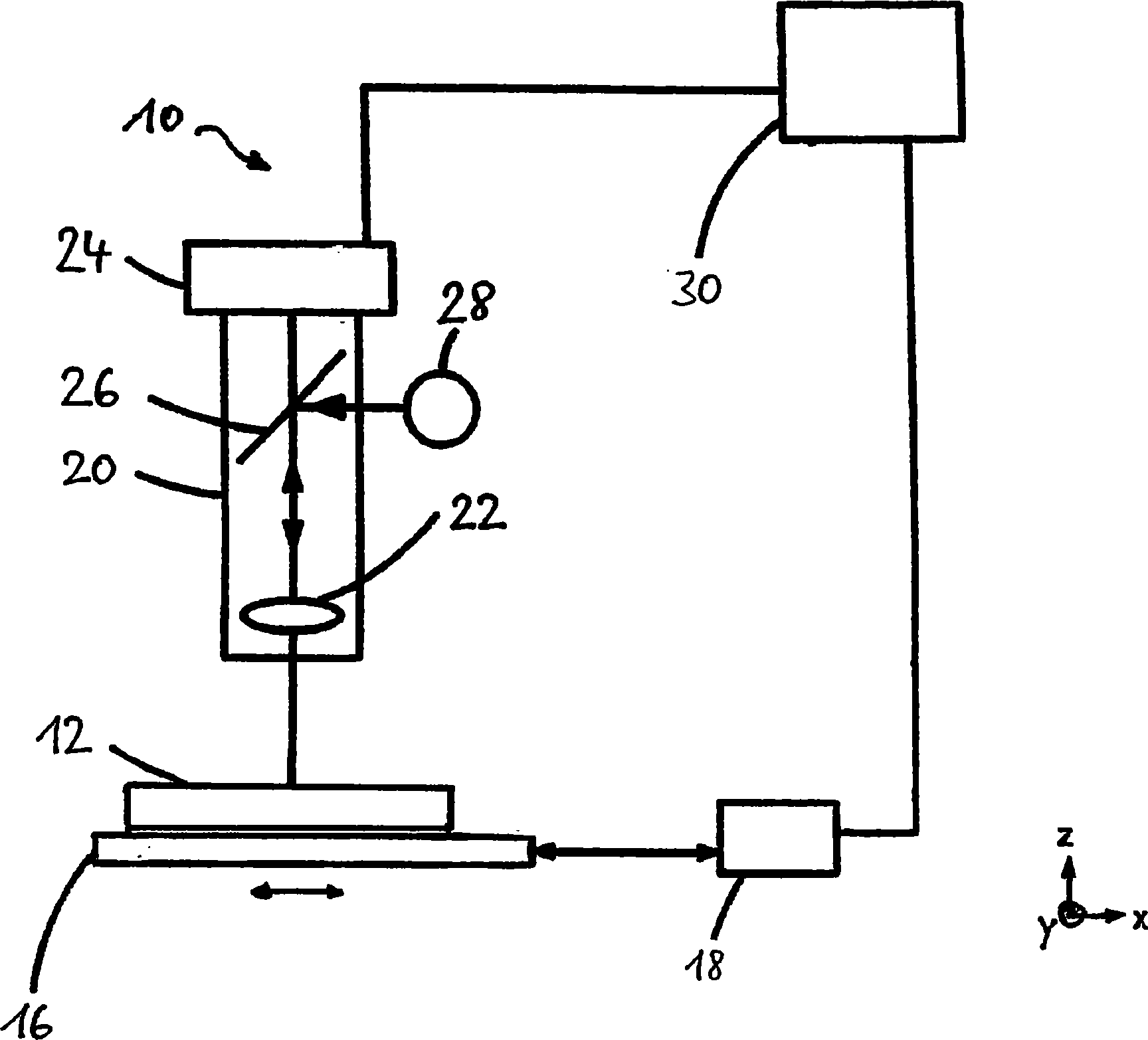
Die Positionsmessvorrichtung
Die Positionsmessvorrichtung
Im Betrieb der Positionsmessvorrichtung
Um die Positionsmessgenauigkeit der Vorrichtung
Die Kalibriermaske
Die in
Unter Littrow-Reflektion versteht man, wie nachstehend näher veranschaulicht, dass eine bestimmte Beugungsordnung einer an einer diffraktiven Struktur in Reflexion gebeugten eingestrahlen Welle im Strahlengang der eingestrahlten Welle zurückläuft.Littrow reflection is understood to mean, as illustrated in more detail below, that a certain order of diffraction of an irradiated wave diffracted by reflection at a diffractive structure in the beam path of the incident wave travels back.
Die diffraktiven Strukturen gemäß den
Daraufhin trifft die Beleuchtungsstrahlung
Wie bereits zuvor erwähnt, wird daraufhin die Kalibriermaske
Das Auswertemodul
Die ermittelten Koordinaten sind insbesondere die Koordinaten der jeweiligen, hinsichtlich der diffraktiven Wirkung der einzelnen Strukturelemente der diffraktiven Strukturen
Daraufhin wird die Kalibriermaske
Die interferometrische Positionsvermessung der diffraktiven Strukturen
Mittels der vorstehend beschriebenen Qualifizierung der Kalibriermaske
Daraufhin wird die Positionsmessvorrichtung
Es kann nicht nur eine einzige Kalibriermaske
So können die diffraktiven Strukturen
Weiterhin können die Kalibriermasken sich darin unterscheiden, dass die diffraktiven Strukturen durch unterschiedliche Herstellungsverfahren erzeugt wurden. So können auf einer ersten Kalibriermaske die diffraktiven Strukturen etwa durch Elektronenstrahlschreiben erzeugt worden sein, während die Erzeugung der diffraktiven Strukturen auf einer anderen Kalibriermaske durch interferometrische/holographische Belichtung mit mehreren Planwellen erfolgt. Werden nun die Positionsfehler der einzelnen diffraktiven Strukturen für die unterschiedlichen Kalibriermasken
BezugszeichenlisteLIST OF REFERENCE NUMBERS
- 1010
- PositionsmessvorrichtungPosition measuring device
- 1212
- Lithographiemaskelithography mask
- 1414
- Messstrukturmeasurement structure
- 1616
- Maskenhaltermask holder
- 1818
- AbstandsmessmodulDistance measuring module
- 2020
- Aufnahmeeinrichtungrecording device
- 2222
- Messobjektivmeasuring lens
- 2424
- Detektordetector
- 2626
- Strahlteilerbeamsplitter
- 2828
- Beleuchtungsquellelighting source
- 3030
- Auswertemodulevaluation module
- 4040
- KalibriermaskeCalibration mask
- 4242
- diffraktive Strukturdiffractive structure
- 42a42a
- Parkettstrukturparquet structure
- 42b42b
- Schachbrettgittercheckerboard grid
- 42c42c
- Ringgitterring grid
- 4444
- eindimensionales Liniengitterone-dimensional line grid
- 46a46a
- Linieline
- 46b46b
- quadratische Flächesquare area
- 46c46c
- Kreiscircle
- 48c48c
- radiale Linieradial line
- 5050
- Interferometerinterferometer
- 5252
- Lichtquellelight source
- 5454
- Beleuchtungsstrahlungillumination radiation
- 5656
- optische Achseoptical axis
- 5858
- Strahlteilerbeamsplitter
- 6060
- Fizeau-ElementFizeau element
- 6262
- Fizeau-FlächeFizeau surface
- 6464
- Referenzwellereference wave
- 6666
- eingehende Messwelleincoming measuring wave
- 6868
- ebene Wellenfrontlevel wavefront
- 7070
- reflektierte Wellereflected wave
- 7272
- InterferometerkameraInterferometerkamera
- 7474
- Objektivsystemlens system
- 7676
- Erfassungsflächedetecting surface
- 7878
- Kamerachipcamera chip
- 8080
- Auswertemodulevaluation module
Claims (10)
Priority Applications (5)
| Application Number | Priority Date | Filing Date | Title |
|---|---|---|---|
| DE102009019140.2A DE102009019140B4 (en) | 2009-04-29 | 2009-04-29 | Method for calibrating a position measuring device and method for measuring a mask |
| US13/266,920 US8617774B2 (en) | 2009-04-29 | 2010-04-10 | Method and calibration mask for calibrating a position measuring apparatus |
| PCT/EP2010/002236 WO2010124791A1 (en) | 2009-04-29 | 2010-04-10 | Method and calibration mask for calibrating a position measuring apparatus |
| CN201080018981.2A CN102414615B (en) | 2009-04-29 | 2010-04-10 | For method and the calibration mask of calibrating position measuring equipment |
| TW099112284A TWI490634B (en) | 2009-04-29 | 2010-04-20 | Method and calibration mask for calibrating a position measuring apparatus |
Applications Claiming Priority (1)
| Application Number | Priority Date | Filing Date | Title |
|---|---|---|---|
| DE102009019140.2A DE102009019140B4 (en) | 2009-04-29 | 2009-04-29 | Method for calibrating a position measuring device and method for measuring a mask |
Publications (2)
| Publication Number | Publication Date |
|---|---|
| DE102009019140A1 DE102009019140A1 (en) | 2010-11-04 |
| DE102009019140B4 true DE102009019140B4 (en) | 2017-03-02 |
Family
ID=42813653
Family Applications (1)
| Application Number | Title | Priority Date | Filing Date |
|---|---|---|---|
| DE102009019140.2A Active DE102009019140B4 (en) | 2009-04-29 | 2009-04-29 | Method for calibrating a position measuring device and method for measuring a mask |
Country Status (5)
| Country | Link |
|---|---|
| US (1) | US8617774B2 (en) |
| CN (1) | CN102414615B (en) |
| DE (1) | DE102009019140B4 (en) |
| TW (1) | TWI490634B (en) |
| WO (1) | WO2010124791A1 (en) |
Families Citing this family (12)
| Publication number | Priority date | Publication date | Assignee | Title |
|---|---|---|---|---|
| JP5575169B2 (en) * | 2012-03-22 | 2014-08-20 | 株式会社ニューフレアテクノロジー | Charged particle beam drawing apparatus and charged particle beam drawing method |
| CN105737879A (en) * | 2016-03-01 | 2016-07-06 | 中国电子科技集团公司第十三研究所 | Micron grade raster calibration sample wafer with step height |
| DE102016204535A1 (en) | 2016-03-18 | 2017-09-21 | Carl Zeiss Smt Gmbh | Measuring microscope for measuring masks for lithographic processes and measuring methods and calibration methods therefor |
| DE102017115367A1 (en) | 2017-07-10 | 2019-01-10 | Carl Zeiss Smt Gmbh | Method for detecting and compensating environmental influences in a measuring microscope |
| EP3502695A1 (en) * | 2017-12-22 | 2019-06-26 | IMEC vzw | A method and a system for analysis of cardiomyocyte function |
| US10890527B2 (en) * | 2018-06-28 | 2021-01-12 | Samsung Electronics Co., Ltd. | EUV mask inspection apparatus and method, and EUV mask manufacturing method including EUV mask inspection method |
| JP7031516B2 (en) * | 2018-07-06 | 2022-03-08 | 株式会社ニューフレアテクノロジー | Irradiation amount correction amount acquisition method, charged particle beam drawing method, and charged particle beam drawing device |
| WO2020126816A1 (en) * | 2018-12-21 | 2020-06-25 | Asml Holding N.V. | Noise correction for alignment signal |
| US10898329B2 (en) * | 2019-01-25 | 2021-01-26 | Edwards Lifesciences Corporation | Testing apparatus for prosthetic device |
| DE102021200109A1 (en) | 2021-01-08 | 2022-07-14 | Carl Zeiss Smt Gmbh | Method for the areal determination of a map of at least one structure parameter of a structured surface of a diffractive optical element |
| WO2024160647A1 (en) * | 2023-01-30 | 2024-08-08 | Trumpf Laser Gmbh | Device and method for processing a workpiece |
| FI20245729A1 (en) * | 2024-06-10 | 2025-12-11 | Teknologian Tutkimuskeskus Vtt Oy | Optical measurement system and optical grating measurement system |
Citations (11)
| Publication number | Priority date | Publication date | Assignee | Title |
|---|---|---|---|---|
| DE19817714A1 (en) * | 1998-04-21 | 1999-11-04 | Leica Microsystems | Method for measuring the position of structures on a mask surface |
| US7081962B2 (en) * | 2003-03-05 | 2006-07-25 | Canon Kabushiki Kaisha | Aberration measuring apparatus for an optical system utilizing soft x-rays |
| DE102005041203A1 (en) * | 2005-08-31 | 2007-03-01 | Carl Zeiss Sms Gmbh | Device for interferometric measurement of phase masks used for e.g. lithography, produces phase shifting interferogram to be applied over phase mask by translating coherence mask and/or diffraction grating in X-Y direction |
| US7247843B1 (en) * | 2006-05-11 | 2007-07-24 | Massachusetts Institute Of Technology | Long-range gap detection with interferometric sensitivity using spatial phase of interference patterns |
| DE69535516T2 (en) * | 1994-01-24 | 2007-10-04 | Asml Holding, N.V. | Lattice grating interferometric alignment system |
| DE102006032053A1 (en) * | 2006-07-10 | 2008-01-17 | Laser-Laboratorium Göttingen eV | Method for periodically modifying a surface of a substrate in a sample surface for structuring e.g. semiconductors comprises producing an illuminating pattern by bending a converging input beam and superimposing resulting bent partial beams |
| US20080043247A1 (en) * | 2004-05-14 | 2008-02-21 | Carl Zeiss Smt Ag | Method of Manufacturing an Optical Element |
| WO2008110239A1 (en) * | 2007-03-15 | 2008-09-18 | Carl Zeiss Smt Ag | Diffractive component, interferometer arrangement, method for qualifying a dual diffraction grating, method of manufacturing an optical element, and interferometric method |
| WO2009007087A1 (en) * | 2007-07-09 | 2009-01-15 | Carl Zeiss Smt Ag | Optical element and method of calibrating a measuring apparatus comprising a wave shaping structure |
| WO2009006914A1 (en) * | 2007-07-06 | 2009-01-15 | Carl Zeiss Smt Ag | Method of measuring a deviation of an actual shape from a target shape of an optical surface |
| DE102007049099A1 (en) * | 2007-10-11 | 2009-04-23 | Vistec Semiconductor Systems Gmbh | Coordinate measuring machine for determining phase relationship of mask i.e. phase shift mask, during manufacture of semiconductor, has optical unit, where phase differences are determined based on optical unit together with detector |
Family Cites Families (14)
| Publication number | Priority date | Publication date | Assignee | Title |
|---|---|---|---|---|
| US3690881A (en) * | 1970-09-28 | 1972-09-12 | Bell Telephone Labor Inc | Moire pattern aligning of photolithographic mask |
| US4588667A (en) | 1984-05-15 | 1986-05-13 | Xerox Corporation | Electrophotographic imaging member and process comprising sputtering titanium on substrate |
| DE10125785A1 (en) | 2001-05-26 | 2002-11-28 | Zeiss Carl | Absolute calibration of interferometer by measuring optical element in four positions and two angular positions, inter-focally and extra-focally |
| US7023562B2 (en) | 2001-09-10 | 2006-04-04 | Zygo Corporation | Characterization of period variations in diffraction gratings |
| US7804994B2 (en) * | 2002-02-15 | 2010-09-28 | Kla-Tencor Technologies Corporation | Overlay metrology and control method |
| US7024066B1 (en) | 2003-04-07 | 2006-04-04 | Luxtera, Inc. | Littrow gratings as alignment structures for the wafer level testing of optical and optoelectronic chips |
| US6936386B2 (en) * | 2003-10-17 | 2005-08-30 | United Microelectronics Corp. | Reticle alignment procedure |
| JP4340638B2 (en) | 2004-03-02 | 2009-10-07 | エーエスエムエル ネザーランズ ビー.ブイ. | Lithographic apparatus, substrate identification method, device manufacturing method, substrate, and computer program for imaging on the front or back side of the substrate |
| TW200538704A (en) | 2004-05-21 | 2005-12-01 | Zetetic Inst | Apparatus and methods for overlay, alignment mark, and critical dimension metrologies based on optical interferometry |
| US7256871B2 (en) * | 2004-07-27 | 2007-08-14 | Asml Netherlands B.V. | Lithographic apparatus and method for calibrating the same |
| US7292326B2 (en) | 2004-11-30 | 2007-11-06 | Molecular Imprints, Inc. | Interferometric analysis for the manufacture of nano-scale devices |
| US7361941B1 (en) | 2004-12-21 | 2008-04-22 | Kla-Tencor Technologies Corporation | Calibration standards and methods |
| US7062397B1 (en) * | 2004-12-23 | 2006-06-13 | Agilent Technologies, Inc. | Recursive calibration |
| DE102007033814B4 (en) | 2007-04-04 | 2014-08-28 | Carl Zeiss Sms Gmbh | Apparatus and method for measuring the position of marks on a mask |
-
2009
- 2009-04-29 DE DE102009019140.2A patent/DE102009019140B4/en active Active
-
2010
- 2010-04-10 WO PCT/EP2010/002236 patent/WO2010124791A1/en not_active Ceased
- 2010-04-10 CN CN201080018981.2A patent/CN102414615B/en active Active
- 2010-04-10 US US13/266,920 patent/US8617774B2/en active Active
- 2010-04-20 TW TW099112284A patent/TWI490634B/en not_active IP Right Cessation
Patent Citations (11)
| Publication number | Priority date | Publication date | Assignee | Title |
|---|---|---|---|---|
| DE69535516T2 (en) * | 1994-01-24 | 2007-10-04 | Asml Holding, N.V. | Lattice grating interferometric alignment system |
| DE19817714A1 (en) * | 1998-04-21 | 1999-11-04 | Leica Microsystems | Method for measuring the position of structures on a mask surface |
| US7081962B2 (en) * | 2003-03-05 | 2006-07-25 | Canon Kabushiki Kaisha | Aberration measuring apparatus for an optical system utilizing soft x-rays |
| US20080043247A1 (en) * | 2004-05-14 | 2008-02-21 | Carl Zeiss Smt Ag | Method of Manufacturing an Optical Element |
| DE102005041203A1 (en) * | 2005-08-31 | 2007-03-01 | Carl Zeiss Sms Gmbh | Device for interferometric measurement of phase masks used for e.g. lithography, produces phase shifting interferogram to be applied over phase mask by translating coherence mask and/or diffraction grating in X-Y direction |
| US7247843B1 (en) * | 2006-05-11 | 2007-07-24 | Massachusetts Institute Of Technology | Long-range gap detection with interferometric sensitivity using spatial phase of interference patterns |
| DE102006032053A1 (en) * | 2006-07-10 | 2008-01-17 | Laser-Laboratorium Göttingen eV | Method for periodically modifying a surface of a substrate in a sample surface for structuring e.g. semiconductors comprises producing an illuminating pattern by bending a converging input beam and superimposing resulting bent partial beams |
| WO2008110239A1 (en) * | 2007-03-15 | 2008-09-18 | Carl Zeiss Smt Ag | Diffractive component, interferometer arrangement, method for qualifying a dual diffraction grating, method of manufacturing an optical element, and interferometric method |
| WO2009006914A1 (en) * | 2007-07-06 | 2009-01-15 | Carl Zeiss Smt Ag | Method of measuring a deviation of an actual shape from a target shape of an optical surface |
| WO2009007087A1 (en) * | 2007-07-09 | 2009-01-15 | Carl Zeiss Smt Ag | Optical element and method of calibrating a measuring apparatus comprising a wave shaping structure |
| DE102007049099A1 (en) * | 2007-10-11 | 2009-04-23 | Vistec Semiconductor Systems Gmbh | Coordinate measuring machine for determining phase relationship of mask i.e. phase shift mask, during manufacture of semiconductor, has optical unit, where phase differences are determined based on optical unit together with detector |
Also Published As
| Publication number | Publication date |
|---|---|
| TWI490634B (en) | 2015-07-01 |
| WO2010124791A1 (en) | 2010-11-04 |
| US8617774B2 (en) | 2013-12-31 |
| DE102009019140A1 (en) | 2010-11-04 |
| TW201109837A (en) | 2011-03-16 |
| US20120160007A1 (en) | 2012-06-28 |
| CN102414615A (en) | 2012-04-11 |
| CN102414615B (en) | 2015-11-25 |
Similar Documents
| Publication | Publication Date | Title |
|---|---|---|
| DE102009019140B4 (en) | Method for calibrating a position measuring device and method for measuring a mask | |
| EP3256835B1 (en) | Test device and method for testing a mirror | |
| DE4031637C2 (en) | Arrangement for measuring a displacement between two objects | |
| DE60118726T2 (en) | IN-SITU MIRROR CHARACTERIZATION | |
| DE69130783T2 (en) | Device for projecting a mask pattern onto a substrate | |
| DE60113153T2 (en) | A method of measuring the orientation of a substrate with respect to a reference alignment mark | |
| DE69225858T2 (en) | Method and device for measuring positional deviations of several diffraction gratings applied to an object | |
| WO2008012091A2 (en) | Method and apparatus for determining a deviation of an actual shape from a desired shape of an optical surface | |
| DE102016212477A1 (en) | Measuring method and measuring system for the interferometric measurement of the imaging quality of an optical imaging system | |
| DE102010041556A1 (en) | Projection exposure apparatus for microlithography and method for microlithographic imaging | |
| WO2003087945A2 (en) | Interferometric measuring device and projection illumination installation comprising one such measuring device | |
| EP4018154A1 (en) | Diffractive optical element for a test interferometer | |
| DE69428327T2 (en) | Method and system for detecting angular deviation using a periodic pattern | |
| EP3123247B1 (en) | Measuring device for determining a polarisation parameter | |
| DE102020207946A1 (en) | Measuring device for the interferometric determination of a surface shape | |
| DE102014209455B4 (en) | Method for measuring a lithography mask or a mask blank | |
| DE102015220588A1 (en) | Measuring method and measuring arrangement for an imaging optical system | |
| WO2017076690A1 (en) | Method and apparatus for characterizing a wafer structured by at least one lithography step | |
| DE102023205623A1 (en) | Method, device and computer program for determining an orientation of a sample on a sample table | |
| DE102020213762B3 (en) | Diffractive optical element for an interferometric measuring device | |
| EP0040700B1 (en) | Method and equipment for checking an optical system | |
| WO2005124274A2 (en) | Calibrating method, measuring method, optical measuring device and operating method for a transmitter arrangement | |
| DE102022213459A1 (en) | Interferometric measurement method | |
| DE102020211819A1 (en) | Measurement method for determining the optical effect of an object | |
| DE102020210529A1 (en) | Method and device for characterizing the surface shape of an optical element |
Legal Events
| Date | Code | Title | Description |
|---|---|---|---|
| OM8 | Search report available as to paragraph 43 lit. 1 sentence 1 patent law | ||
| R012 | Request for examination validly filed |
Effective date: 20120718 |
|
| R079 | Amendment of ipc main class |
Free format text: PREVIOUS MAIN CLASS: G03F0009000000 Ipc: G01B0011030000 Effective date: 20120921 |
|
| R016 | Response to examination communication | ||
| R081 | Change of applicant/patentee |
Owner name: CARL ZEISS SMT GMBH, DE Free format text: FORMER OWNER: CARL ZEISS SMS GMBH, 07745 JENA, DE |
|
| R082 | Change of representative |
Representative=s name: ZEUNER SUMMERER STUETZ PATENT- UND RECHTSANWAL, DE |
|
| R016 | Response to examination communication | ||
| R016 | Response to examination communication | ||
| R018 | Grant decision by examination section/examining division | ||
| R020 | Patent grant now final |