DE102008008707A1 - Digital image processing method, involves forming mixed model description depending upon verification, and calculating image values of processed images by considering imaging function from result of mixed model description - Google Patents
Digital image processing method, involves forming mixed model description depending upon verification, and calculating image values of processed images by considering imaging function from result of mixed model description Download PDFInfo
- Publication number
- DE102008008707A1 DE102008008707A1 DE200810008707 DE102008008707A DE102008008707A1 DE 102008008707 A1 DE102008008707 A1 DE 102008008707A1 DE 200810008707 DE200810008707 DE 200810008707 DE 102008008707 A DE102008008707 A DE 102008008707A DE 102008008707 A1 DE102008008707 A1 DE 102008008707A1
- Authority
- DE
- Germany
- Prior art keywords
- image
- model
- pixel
- picture element
- values
- Prior art date
- Legal status (The legal status is an assumption and is not a legal conclusion. Google has not performed a legal analysis and makes no representation as to the accuracy of the status listed.)
- Withdrawn
Links
Classifications
-
- G—PHYSICS
- G06—COMPUTING OR CALCULATING; COUNTING
- G06T—IMAGE DATA PROCESSING OR GENERATION, IN GENERAL
- G06T3/00—Geometric image transformations in the plane of the image
- G06T3/40—Scaling of whole images or parts thereof, e.g. expanding or contracting
Landscapes
- Physics & Mathematics (AREA)
- General Physics & Mathematics (AREA)
- Engineering & Computer Science (AREA)
- Theoretical Computer Science (AREA)
- Image Processing (AREA)
Abstract
Description
Die Erfindung betrifft ein Verfahren zum Bearbeiten von digitalen Bildern, wobei unter Verwendung einer Abbildungsfunktion aus einem digitalen Rohbild ein Bild (im folgenden: „das bearbeitete Bild") erzeugt wird und wobei Bildwerte von Bildelementen des bearbeiteten Bildes unter Berücksichtigung der Abbildungsfunktion berechnet werden. Die Erfindung betrifft insbesondere die Bearbeitung von Fernerkundungs-Bilddaten und hier, insbesondere spezieller, das Teilgebiet der Entzerrung der aufgenommenen Bilder.The The invention relates to a method for processing digital images, using a mapping function from a digital Raw picture a picture (in the following: "the edited picture") is produced and taking picture values of picture elements of the edited picture under consideration of the mapping function. The invention relates especially the processing of remote sensing image data and here, In particular, more specifically, the sub-field of equalization of the recorded Images.
Bei der Bearbeitung von digitalen Bildern, bei denen das ursprüngliche Bildraster nicht erhalten bleibt, wie z. B. bei der Entzerrung von Bildern ist bekanntermaßen ein so genanntes Resampling durchzuführen, wodurch die Intensitäten (z. B. Grauwerte und/oder Farbwerte) der Bildelemente (Pixel) in dem Raster des bearbeiteten Bildes berechnet werden. Die Intensitäten werden auch als Bildwerte bezeichnet. Unter dem Bildraster wird die Anordnung der Bildelemente im Bild verstanden.at the editing of digital images in which the original Image grid is not preserved, such. B. in the equalization of Pictures are known perform a so-called resampling, whereby the intensities (z. Gray values and / or color values) of the picture elements (pixels) in the Raster of the edited image are calculated. The intensities will be also referred to as image values. Under the image grid is the arrangement understood the picture elements in the picture.
Üblicherweise wird zunächst aus der Beziehung zwischen dem Raster des bearbeiteten Bildes und dem Raster des Rohbildes die Abbildungsfunktion ermittelt. Im Ergebnis liegt dann im Koordinatensystem des Rohbildes das entsprechend der Abbildungsfunktion verzerrte Raster des bearbeiteten Bildes vor, d. h. die Bildelemente des bearbeiteten Bildes weisen z. b. divergierende (nicht parallel zueinander verlaufende und in der Regel nicht geradlinige Grenzlinien auf). Durch die Entzerrung des Rohbildes, in dem die Bildelemente in orthogonal zueinander verlaufenden geradlinigen Reihen und Spalten angeordnet sind, werden z. B. (wie auch bei einem Ausführungsbeispiel der Erfindung) die Orte der Eckpunkte der Bildelemente des Rohbildes auf solche divergierenden, nicht notwendigerweise geradlinig verlaufenden Linien abgebildet. In einem Bildraster des neuen, entzerrten Bildes, sind dann jedoch z. B. wieder Bildelemente definiert, die in orthogonal zueinander verlaufenden geradlinigen Reihen und Spalten angeordnet sind. Wie erwähnt ist es daher typisch für die Bildbearbeitung Orte des Rasters des bearbeiteten Bildes im Bildraster des Rohbildes mittels einer definierten Abbildungsfunktion zu berechnen und die Intensitäten der Bildelemente des bearbeiteten Bildes dementsprechend zu berechnen. Dies wird als Resampling bezeichnet.Usually will be first from the relationship between the raster of the edited image and the Raster of the raw image determines the imaging function. In the result then lies in the coordinate system of the raw image according to the Imaging function distorted raster of edited image, d. H. the picture elements of the edited image have z. b. diverging (not parallel to each other and usually not rectilinear Borderlines). By the equalization of the raw picture, in which the Pixels in orthogonal rectilinear Rows and columns are arranged, z. B. (as well as a embodiment the invention) the locations of the vertices of the picture elements of the raw image to such divergent, not necessarily straightforward Lines shown. In a picture grid of the new, rectified image, but then z. B. again defined pixels in orthogonal arranged to each other extending rectilinear rows and columns are. As mentioned It is therefore typical for the image editing places the grid of the edited image in Image grid of the raw image by means of a defined mapping function to calculate and the intensities the pixels of the edited image accordingly. This is called resampling.
Je geringer die geometrische Auflösung des Rohbildes ist, desto häufiger enthält ein Bildelement des Rohbildes Anteile von verschiedenen realen (durch das Bild dargestellten) Objekten, die somit im Bild nicht mehr getrennt werden können. Dieser Fall ist häufig bei Bildern anzutreffen, die durch Fernerkundung (z. B. durch Kameras oder Scanner in Satelliten oder Flugzeugen) aufgenommen wurden. Die Erfindung betrifft insbesondere die Bearbeitung von Bildern aus einer solchen Fernerkundung, kann aber auch sinnvoll für andere Aufgaben angewendet werden, bei denen Bilder, die relativ viele Mischelemente (Bildelemente mit Anteilen aus verschiedenen Objekten) enthalten in eine andere Geometrie gebracht werden sollen.ever lower the geometric resolution the raw picture is the more common contains a picture element of the raw image shares of different real (by the picture shown) objects, which are thus no longer separated in the picture can be. This case is common in images obtained by remote sensing (eg, by cameras or scanners in satellites or aircraft). The invention relates in particular to the processing of images from such a remote sensing, but may also be useful for other tasks be applied, which images, the relatively many mixing elements (Picture elements with shares from different objects) to be brought into a different geometry.
Wegen der Unkenntnis der wahren Intensitätsverteilung innerhalb der einzelnen Bildelemente entstehen beim Resampling Fehler. Zweck der Erfindung ist es, die Genauigkeit des Resamplings zu verbessern und damit das erzeugte Bild wirklichkeitsgetreuer zu machen.Because of ignorance of the true distribution of intensity within the individual picture elements arise during the resampling error. Purpose of Invention is to improve the accuracy of the resampling and to make the picture more realistic.
Bekannte Resamplingverfahren kann man in vier Arten unterteilen.
- 1. Das einfachste Verfahren ist das Nearest-Neighbour-Verfahren, bei dem der Bildwert (z. B. Grauwert) desjenigen Bildelementes verwendet wird, welches der berechneten Position am nächsten liegt. Dieses Verfahren produziert zwar optisch scharfe Bilder, erzeugt jedoch speziell an kontrastreichen Bildstrukturen wie z. B. Objektkanten sehr große Fehler.
- 2. Etwas geringere Fehler erhält man bei der bilinearen Interpolation. Bei diesem Verfahren gehen je nach Lage der berechneten Position die Bildwerte von ein bis vier Bildelementen in die Berechnung des Resamplingwertes ein. Die Wichtung erfolgt nach dem Abstand zwischen der errechneten Position und dem betreffenden Bildelement. Dieses Verfahren erzeugt durch die Verschleifung von scharfen Strukturen unscharfe Bilder.
- 3. Eine weitere Gruppe von Verfahren benutzt zentralsymmetrische Wichtungsfunktionen, bei denen das größte Gewicht an der berechneten Position liegt und die gleich einer gedämpften Schwingung mit zunehmendem Abstand abklingen. Ausgangspunkt für diese Art von Wichtungsfunktionen ist die sinx/x-Funktion. Diese Verfahren, zu denen z. B. die kubische Faltung gehört, erzeugen schärfere Bilder als die bilineare Interpolation und rufen kleinere Fehler als das Nearest-Neighbour-Verfahren hervor. Ein wesentlicher Nachteil ist aber, dass bei bestimmten Bildstrukturen durch die negativen Anteile der Wichtungsfunktionen negative Resamplingwerte entstehen können.
- 4. Aus diesem Grunde wurde noch eine andere Gruppe von Verfahren entwickelt, die ebenfalls zentralsymmetrische Wichtungsfunktionen verwendet. Diese Funktionen verlaufen aber nur im positiven Bereich. Sie haben ihr Maximum ebenfalls an der berechneten Position und fallen von dort aus mit wachsendem Abstand ab. Die Eigenschaften dieser Gruppe liegen zwischen der bilinearen Interpolation und den Wichtungsfunktionen der dritten Gruppe (sinx/x-Prinzip).
- 1. The simplest method is the Nearest Neighbor method, which uses the image value (eg, gray value) of the pixel closest to the calculated position. Although this method produces visually sharp images, but produces especially on high-contrast image structures such. B. Object edges very large errors.
- 2. Slightly lower errors are obtained in bilinear interpolation. Depending on the position of the calculated position, the image values of one to four pixels are included in the calculation of the resampling value. The weighting takes place according to the distance between the calculated position and the relevant picture element. This process produces blurred images by blurring sharp structures.
- 3. Another group of methods uses center-symmetric weighting functions in which the largest weight is at the calculated position and which equal to a damped vibration decays with increasing distance. The starting point for this type of weighting function is the sinx / x function. These methods, which z. For example, when cubic convolution is heard, sharper images are produced than bilinear interpolation and cause smaller errors than the nearest neighbor method. A significant disadvantage, however, is that with certain image structures, negative resampling values can arise due to the negative components of the weighting functions.
- 4. For this reason, yet another group of methods has been developed that also uses center-symmetric weighting functions. These functions are only positive. You also have your maximum at the calculated position and fall from there with increasing Ab stood off. The properties of this group lie between the bilinear interpolation and the weighting functions of the third group (sinx / x principle).
Alle bekannten Resamplingverfahren haben jedoch zusätzlich zu den schon genannten verfahrensspezifischen Mängeln folgende gemeinsamen Nachteile:
- a) Keines dieser Verfahren beachtet die wirkliche Form und Ausdehnung der Fläche, die den Resamplingwert beeinflusst.
- b) Alle genannten Verfahren betrachten die Elemente des Rohbildes, aus denen der Resamplingwert berechnet wird, als homogen (d. h. einen konstanten Bildwert aufweisend), was in der Realität nur selten der Fall ist.
- c) Keines der bekannten Verfahren stellt sicher, dass das Intensitätsintegral über eine beliebige Fläche im Raster des Rohbildes erhalten bleibt.
- a) None of these methods takes into account the actual shape and extent of the area that affects the resampling value.
- b) All these methods consider the elements of the raw image from which the resampling value is calculated to be homogeneous (ie having a constant image value), which is rarely the case in reality.
- c) None of the known methods ensures that the intensity integral is maintained over any area in the raster of the raw image.
Alle genannten allgemeinen und verfahrensspezifischen Mängel der bisher bekannten Verfahren führen zu Intensitätsfehlern im resampelten Bild.All general and procedural deficiencies lead previously known methods to intensity errors in the resampled picture.
Ziel der Erfindung ist es, durch Vermeidung oder Abschwächung der genannten Mängel sowohl den mittleren (über das Bild oder einen Teilbereich des Bildes gemittelten) als auch den maximalen (an einem beliebigen Ort des Bildes auftretenden) Resamplingfehler zu verringern.aim The invention is to avoid or mitigate the mentioned defects both the middle (above the image or a portion of the image averaged) as well the maximum (occurring at any location of the image) Reduce resampling errors.
Grundlegende Überlegungen,
von denen die Erfindung ausgeht, sind wie folgt:
Um ein fehlerloses
Resampling zu erreichen, müsste
das Rohbild unendlich fein aufgelöst sein, da der Resamplingwert
(d. h. der Bildwert des bearbeiteten Bildes) durch Integration der
Bildwerte des Rohbildes über die
durch die Abbildungsfunktion vorgegebene Fläche des neuen Bildelementes
berechnet wird.Basic considerations underlying the invention are as follows:
In order to achieve a flawless resampling, the raw image would have to be finely resolved since the resampling value (ie the image value of the processed image) is calculated by integrating the image values of the raw image over the area of the new pixel given by the mapping function.
Ein anderer Fall, bei dem auch ein fehlerloser Resamplingwert entsteht, besteht, wenn der Bildwert in der durch das Bildelement erfassten Bildfläche völlig homogen ist. Bei völliger Homogenität sind alle Resamplingverfahren gleichwertig. Beide Fälle kommen bezogen auf ein ganzes Bild in der Realität nicht vor.One another case where a flawless resampling value is created, exists when the image value in the captured by the pixel scene completely is homogeneous. In complete homogeneity All resampling methods are equivalent. Both cases are coming in relation to a whole picture in reality not present.
Um das Resampling trotzdem zu verbessern, ist es ein Grundgedanke der vorliegenden Erfindung, die Auflösung des Rohbildes durch Modelle zu verbessern, d. h. zu verfeinern.Around to improve the resampling anyway, it is a basic idea of present invention, the resolution of the raw image through models to improve, d. H. to refine.
Bevorzugtermaßen sollen die Modelle prinzipiell dazu in der Lage sein, eine beliebig feine Auflösung zu erzielen. Die tatsächlich erzielte Auflösung kann insbesondere von dem Rohbild abhängen. Das bedeutet aber nicht, dass der Intensitätsverlauf innerhalb der Bildelemente mit dieser feinen Auflösung exakt wiedergegeben wird, sondern nur näherungsweise. Insbesondere kann die von dem Modell erzielte Auflösung über die Bildfläche variieren.Preferred dimensions are intended the models in principle to be able to any arbitrary fine Resolution too achieve. Actually achieved resolution may depend in particular on the raw image. But that does not mean that the intensity course within the picture elements with this fine resolution exactly is reproduced, but only approximately. Especially For example, the resolution achieved by the model may vary across the image area.
Gemäß der Erfindung werden zumindest zwei verschiedene Modelle verwendet. Vorzugsweise werden zwei Modelle verwendet. Es können jedoch auch mehr als zwei Modelle verwendet werden. Die Anzahl der Modelle ist nicht begrenzt. In der Praxis jedoch wird man aus Gründen der Begrenzung des Rechenaufwandes die Anzahl der Modelle begrenzen. Bevorzugtermaßen wird zumindest eines der Modelle verwendet, die noch in der Figurenbeschreibung beschrieben werden.According to the invention At least two different models are used. Preferably Two models are used. However, there may be more than two Models are used. The number of models is not limited. In practice, however, one will for reasons of limiting the computational effort limit the number of models. Preferably, at least one of Models used that are still described in the figure description become.
Die Eigenschaften der verwendeten Modelle sollten sich möglichst deutlich unterscheiden. Z. B. können in den Modellen mathematische Funktionen verwendet werden, die innerhalb eines Bildelementes ein oder mehrere Extremwerte annehmen. Die Funktionen beschreibenden z. B. den Bildwert in Abhängigkeit des Ortes im Bild.The Properties of the models used should be as possible clearly distinguish. For example, you can in the models mathematical functions are used within of a picture element assume one or more extreme values. The functions descriptive z. B. the image value depending on the location in the image.
Insbesondere wird ein Verfahren zum Bearbeiten von digitalen Bildern vorgeschlagen, wobei
- – unter Verwendung einer Abbildungsfunktion aus einem digitalen Rohbild ein bearbeitetes Bild erzeugt wird. Insbesondere kann ein orthogonales (z. B. quadratisches) Raster des bearbeiteten Bildes gewählt werden, sodass die Abbildungsfunktion die geometrische Beziehung zwischen dem Raster des Rohbilds und dem Raster des bearbeiteten Bildes definiert.
- – Bildwerte von Bildelementen des bearbeiteten Bildes unter Berücksichtigung der Abbildungsfunktion berechnet werden (dies wird als Resampling bezeichnet).
- A processed image is generated using a mapping function from a raw digital image. In particular, an orthogonal (eg, square) raster of the processed image may be chosen such that the mapping function defines the geometric relationship between the raster of the raw image and the raster of the processed image.
- - Image values of pixels of the processed image are calculated taking into account the mapping function (this is called resampling).
Das Resampling enthält Folgendes:
- a) Das Rohbild wird durch zumindest zwei verschiedene mathematische Modelle beschrieben, wobei jedes Modell ausgestaltet ist, Bildwerte eines Rohbildes ohne vorgegebene örtliche Rasterung in Abhängigkeit des Bildortes zu beschreiben, sodass das Rohbild durch das jeweilige Modell mit feinerer örtlicher Auflösung beschreibbar ist.
- b) Zumindest in Teilbereichen des Rohbildes wird für jedes Bildelement geprüft, welches Modell die örtliche Abhängigkeit der Bildwerte innerhalb des Bildelementes (wahrscheinlich) besser wiedergibt, und/oder es wird zumindest in den Teilbereichen für jedes Bildelement ein Modell daraufhin geprüft, ob es die örtliche Abhängigkeit der Bildwerte entsprechend einem vorgegebenen Güte-Kriterium beschreibt. Vorzugsweise wird jedes Bildelement des Rohbildes derart geprüft.
- c) Abhängig von der Prüfung wird gegebenenfalls eine gemischte Modellbeschreibung gebildet, in der die örtliche Abhängigkeit der Bildwerte in verschiedenen Bildelementen des Rohbildes durch verschiedene mathematische Modelle (d. h. in jedem Bildelement durch eines der zumindest zwei verschiedenen mathematische Modelle) beschrieben wird.
- d) Bildwerte des bearbeiteten Bildes werden unter Berücksichtigung der Abbildungsfunktion aus dem Resultat der gemischten Modellbeschreibung (insbesondere durch Integration über eine Teil-Fläche des Rohbildes wie es durch die gemischte Modellbeschreibung beschrieben wird) berechnet.
- a) The raw image is described by at least two different mathematical models, each model being designed, image values of a raw image without predetermined local screening depending on of the image location so that the raw image can be described by the respective model with a finer spatial resolution.
- b) At least in partial areas of the raw image, it is checked for each pixel which model (probably) better reflects the local dependence of the image values within the pixel and / or at least in the partial areas for each pixel a model is checked to see if it is the local Dependence of image values according to a given quality criterion describes. Preferably, each pixel of the raw image is checked in such a way.
- c) Depending on the test, a mixed model description is formed if necessary, in which the spatial dependence of the image values in different pixels of the raw image is described by different mathematical models (ie in each pixel by one of the at least two different mathematical models).
- d) Image values of the processed image are calculated taking into account the mapping function from the result of the mixed model description (in particular by integration over a partial area of the raw image as described by the mixed model description).
Insbesondere wenn kein Referenzbild für die Prüfung in Schritt b) zur Verfügung steht, werden für zumindest ein zu prüfendes Bildelement des Rohbildes vorzugsweise folgende Schritte ausgeführt:
- – Es werden Parameter einer Modellfunktion bestimmt, die den örtlichen Verlauf der Bildwerte des Rohbildes, wie er durch ein bestimmtes Modell in einer Nachbarschaft des Bildelementes beschrieben wird, lediglich begrenzt auf die Nachbarschaft wiedergibt. Anders ausgedrückt wird die Modellfunktion im Bereich der Nachbarschaft in das Modell gefittet. Dabei kann es sich bei der Modellfunktion um eine Funktion handeln, die bereits in mindest einem der Modelle verwendet wurde, z. B. als Zwischenschritt bei der Berechnung der Bildwerte mit feinerer örtlicher Auflösung. Die Nachbarschaft des Bildelementes wird durch zumindest einen Teilbereich des zu prüfenden Bildelements selbst und durch einen weiteren, dem zu prüfenden Bildelement benachbarten Bereich gebildet. Der weitere Bereich liegt lediglich auf einer Seite des zu prüfenden Bildelementes. Beispielsweise wird der weitere Bereich durch die Fläche der (zwei oder mehr; die Mindestanzahl ist durch die verwendete Funktion definiert) Bildelemente des Rohbildes definiert, die sich auf der Seite ausgehend von dem Rand des zu prüfenden Bildelementes hintereinander in geradliniger Richtung erstrecken, z. B. in Zeilenrichtung oder Spaltenrichtung, je nachdem um welche Seite es sich handelt. Z. B. kann ein Bildelement in einem orthogonalen Raster mit Bildelementen, die in Zeilen und Spalten angeordnet sind, vier Seiten haben, jeweils zwei Seiten einander gegenüberliegend in Spaltenrichtung und zwei Seiten einander gegenüberliegend in Zeilenrichtung. Z. B. zwei dieser Seiten (d. h. eine Seite in Zeilenrichtung und eine Seite in Spaltenrichtung können jedoch alternativ auch als eine Seite aufgefasst werden, sodass das Bildelement lediglich zwei Seiten hat. Als Ergebnis der Nachbarschaft wird ein erster Parametersatz der Modellfunktion erhalten, d. h. eine erste parametrisierte Modellfunktion.
- – Der zuvor genannte Schritt wird auch für zumindest eine weitere Nachbarschaft durchgeführt, wobei der weitere Bereich dieser Nachbarschaft auf einer anderen Seite des zu prüfenden Bildelementes liegt, sodass für jede weitere Nachbarschaft ein weiterer Parametersatz erhalten wird, d. h. je eine weitere parametrisierte Modellfunktion.
- – Für zumindest einen Ort innerhalb des zu prüfenden Bildelementes oder am Rand des zu prüfenden Bildelementes werden die Bildwerte berechnet, die sich mit der Modellfunktion aus den verschiedenen Parametersätzen ergeben, d. h. aus den parametrisierten Modellfunktionen.
- – Die vorangegangenen Schritte werden für die verschiedenen Modelle ausgeführt. Es wird verglichen, welches Modell an einem oder mehreren Orten des zu prüfenden Bildelementes zu der geringsten Streuung in den aus den Parametersätzen der verschiedenen Nachbarschaften berechneten Bildwerten führt und es wird entschieden, dass das Modell mit der geringsten Streuung das Bildelement in der gemischten Modellbeschreibung beschreiben soll. Im einfachsten Fall, wenn lediglich zwei Parametersätze vorhanden sind, ist die Streuung die Differenz der Bildwerte.
- – Alternativ zu dem vorhergehend genannten Schritt, werden die davor genannten Schritte für ein Modell (separat von dem oder den anderen Modellen oder ausschließlich nur für ein Modell) ausgeführt. Es wird geprüft, ob Abweichungen an einem oder mehreren Orten des zu prüfenden Bildelementes, die sich für die verschiedenen Nachbarschaften ergeben, das vorgegebene Güte-Kriterium erfüllen, und es wird bei Nichterfüllung des Güte-Kriteriums entschieden, dass das zu prüfende Pixel in der gemischten Modellbeschreibung durch ein anderes Modell zu beschreiben ist.
- - Parameters of a model function are determined, which reflects the local course of the image values of the raw image, as described by a specific model in a neighborhood of the pixel, only limited to the neighborhood. In other words, the model function is fitted in the vicinity of the model. The model function may be a function that has already been used in at least one of the models, e.g. B. as an intermediate step in the calculation of image values with finer local resolution. The neighborhood of the picture element is formed by at least a partial area of the picture element to be tested itself and by another area adjacent to the picture element to be tested. The further area lies only on one side of the picture element to be tested. For example, the further area is defined by the area of (two or more, the minimum number is defined by the function used) picture elements of the raw image which extend in a straight line on the side starting from the edge of the picture element under test, e.g. In the row direction or column direction, depending on which side it is. For example, a pixel in an orthogonal raster having picture elements arranged in rows and columns may have four sides, two sides opposite one another in the column direction and two sides opposite to each other in the row direction. For example, two of these pages (ie one page in the row direction and one page in the column direction may alternatively be construed as one page so that the picture element has only two pages.) As a result of the neighborhood, a first parameter set of the model function is obtained, ie a first parameterized model function ,
- The aforementioned step is also carried out for at least one further neighborhood, wherein the further area of this neighborhood lies on another side of the picture element to be checked, so that for each further neighborhood a further parameter set is obtained, ie one more parameterized model function.
- For at least one location within the picture element to be checked or at the edge of the picture element to be checked, the picture values which result from the model parameter function from the various parameter sets, ie from the parameterized model functions, are calculated.
- - The previous steps are performed for the different models. It is compared which model at one or more locations of the pixel under test leads to the least scatter in the image values calculated from the parameter sets of the different neighborhoods and it is decided that the model with the lowest dispersion is to describe the pixel in the mixed model description , In the simplest case, if there are only two parameter sets, the scatter is the difference of the image values.
- - As an alternative to the previous step, the above steps are performed for a model (separate from the other model (s), or only for one model). It is checked whether deviations at one or more locations of the pixel under test, which result for the different neighborhoods, meet the predetermined quality criterion, and it is decided in case of failure of the goodness criterion that the pixel under test in the mixed Model description is to be described by another model.
Allgemeiner formuliert kann dann, wenn kein Referenzbild vorhanden ist, der örtliche Verlauf der von dem Modell gelieferten Bildwerte an verschiedenen Seiten des zu prüfenden Bildelementes untersucht werden. Dabei ist unter Verlauf zu verstehen, dass die Richtung des Verlaufs quer (z. B. senkrecht) zu einer Grenze des zu prüfenden Bildelementes ist. Der Verlauf muss dabei auch das zu prüfende Bildelement erfassen.general formulated can, if no reference image is present, the local History of the image values provided by the model at different Pages of the to be tested Picture element are examined. This is to be understood by course, that the direction of the course is transverse (eg perpendicular) to a boundary of the test to be tested Picture element is. The course also has to be the picture element to be checked to capture.
Insbesondere wenn ein Referenzbild für die Prüfung in Schritt b) zur Verfügung steht, werden bei der Prüfung für zumindest ein zu prüfendes Bildelement des Rohbildes folgende Schritte ausgeführt:
- – Für zumindest einen Teilbereich des Rohbildes werden Quotienten der aus dem zu prüfenden Modell oder den zu prüfenden Modellen einerseits und den Bildwerten des Referenzbildes andererseits gebildet, sodass für jedes zu prüfende Modell ein Quotienten-Bild entsteht. Dabei kann durch den Bildwert des Referenzbildes geteilt werden oder durch den Bildwert des Modells.
- – Für das zu prüfende Bildelement wird ein Maß berechnet, das beschreibt, wie ausgeprägt ein gegebenenfalls an einem Ort in dem zu prüfenden Bildelement vorhandenes lokales Extremum der Bildwerte des Quotienten-Bildes im Vergleich zu der Umgebung des Bildelementes ist. Das Maß ist z. B. die größte Differenz des Extremwertes zu einem der acht Umgebungswerte (d. h. Werte der acht unmittelbar benachbarten Bildelemente) in einer 3 × 3 Nachbarschaft. Alternativ wird für ein zu prüfendes Bildelement und seine Umgebung ermittelt, ob der Bildwert des Quotienten-Bildes innerhalb der Umgebung ein Extremwert bezüglich einer geringeren Anzahl von Umgebungswerten, z. B. mindestens zwei gegenüberliegenden Umgebungswerten ist.
- – Die vorangegangenen Schritte werden für die verschiedenen Modelle ausgeführt. Es wird ermittelt, welches Modell an einem oder mehreren Orten des zu prüfenden Bildelementes ein lokales Extremum aufweist und gegebenenfalls in welchem Modell der Extremwert am geringsten ausgeprägt (z. B. das Maß den geringsten Wert liefert) ist. Es wird entschieden, dass das Modell mit der geringsten Ausprägung des lokalen Extremums bzw. ein Modell ohne Extremwert das Bildelement in der gemischten Modellbeschreibung beschreiben soll.
- – Alternativ zu dem vorhergehend genannten Schritt, werden die davor genannten Schritte für ein Modell (separat von dem oder den anderen Modellen oder ausschließlich nur für ein Modell) ausgeführt. Es wird geprüft, ob das Modell an einem oder mehreren Orten des zu prüfenden Bildelementes ein lokales Extremum aufweist. Es wird bei Vorhandensein des Extremums entschieden, dass das zu prüfende Pixel in der gemischten Modellbeschreibung durch ein anderes Modell zu beschreiben ist, oder dann durch ein anderes Modell zu beschreiben ist, wenn die Ausprägung des Extremums in dem anderen Modell geringer ist.
- For at least a subarea of the raw image, quotients of the models to be tested or the models to be tested on the one hand and the image values of the reference image on the other hand are formed so that a quotient image is produced for each model to be tested. It can be divided by the image value of the reference image or by the image value of the model.
- For the picture element to be checked, a measure is calculated which describes how pronounced a local extremum of the image values of the quotient image, if appropriate at a location in the picture element to be tested, is in comparison to the surroundings of the picture element. The measure is z. For example, the maximum difference of the extreme value to one of the eight environmental values (ie, values of the eight immediately adjacent pixels) in a 3 × 3 neighborhood. Alternatively, for a pixel under test and its environment, it is determined whether the image value of the quotient image within the environment is an extreme value with respect to a lower number of environmental values, e.g. B. is at least two opposite environmental values.
- - The previous steps are performed for the different models. It is determined which model has a local extremum at one or more locations of the pixel under test and, if appropriate, in which model the extreme value is the least pronounced (eg the measure gives the lowest value). It is decided that the model with the lowest expression of the local extremum or a model without extreme value should describe the picture element in the mixed model description.
- - As an alternative to the previous step, the above steps are performed for a model (separate from the other model (s), or only for one model). It is checked whether the model has a local extremum at one or more locations of the pixel under test. It is decided in the presence of the extremum that the pixel to be tested in the mixed model description is to be described by another model, or to be described by another model when the expression of the extremum in the other model is lower.
Das erfindungsgemäße Verfahren wird z. B. auf einem handelsüblichen Computer oder Computernetz ausgeführt. Zum Umfang der Erfindung gehört daher auch eine Vorrichtung zur Ausführung des Verfahrens, z. B. ein Computer oder ein Computernetz, wobei die Vorrichtung Mittel (z. B. Software) aufweist, die ausgestaltet sind, das Verfahren in einer seiner Ausgestaltungen auszuführen.The inventive method is z. B. on a commercial Computer or computer network. The scope of the invention belongs Therefore, a device for carrying out the method, for. B. a computer or a computer network, wherein the device means (eg, software) that are configured, the method in one of its embodiments.
Ausführungsbeispiele der Erfindung werden nun unter Bezugnahme auf die beigefügte Zeichnung beschrieben. Die einzelnen Figuren der Zeichnung zeigen:embodiments The invention will now be described with reference to the accompanying drawings described. The individual figures of the drawing show:
Beim kontinuierlichen Modell wird ein lokaler Bereich des Rohbildes durch eine mathematische Funktion beschrieben. Die Art der Funktion bestimmt dabei die Größe des lokalen Bereichs. Wird z. B. eine quadratische Funktion (d. h. ein Polynom zweiten Grades) verwendet, so benötigt man drei Stützwerte, also drei Bildelemente. Bei anderen Ausführungsformen des kontinuierlichen Modells können jedoch andere mathematische Funktionen verwendet werden. Dies gilt auch für die weiter unten beschriebenen Modellfunktionen zur Ermittlung des besten mathematischen Modells.At the continuous model is going through a local area of the raw image described a mathematical function. The type of function determines doing the size of the local Range. If z. A quadratic function (i.e., a polynomial second degree), so you need three support values, So three picture elements. In other embodiments of the continuous Model can however, other mathematical functions are used. this applies also for the model functions described below for determining the best mathematical model.
Das
kontinuierliche Modell soll nun beispielhaft anhand einer quadratischen
Funktion erläutert
werden. Es ist also eine quadratische Funktion zu finden, deren
Integration über
die Breite bzw. Länge
des jeweiligen Bildelementes genau den zugehörigen Bildwert ergibt. Die
Bildwerte dreier aufeinander folgender Bildelemente (z. B. der Folge
aus den Bildelementen 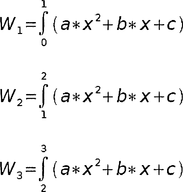
Durch
die Berechnung der drei Integrale erhält man: 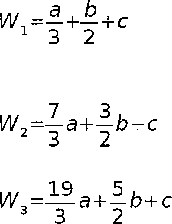
In
gleicher Weise wird nun eine weitere quadratische Funktion aus den
um ein Bildelement versetzten Bildelementen (z. B. Pixel
Um
den notwendigen kontinuierlichen Übergang zwischen den jetzt
zwei vorliegenden quadratischen Funktionen zu gewährleisten,
wird eine abstandsabhängige
Wichtung eingeführt.
Das einzelne Gewicht ergibt sich z. B. bei linear abfallender Wichtung
aus
Es können jedoch auch andere abstandsabhängige Wichtungen benutzt werden. Auf diese Weise kann eine kontinuierliche Bildwerte-Funktion (im Folgenden auch „Intensitätsfunktion" genannt) in Richtung einer Bildachse hergestellt werden und ebenfalls durch dasselbe Verfahren in Richtung der zweiten Bildachse (die i. d. R. senkrecht zur ersten Bildachse verläuft) eine kontinuierliche zweidimensionale Intensitätsfunktion über das ganze Bild.It can but also other distance-dependent Weights are used. This way can be a continuous Image values function (also called "intensity function" in the following) in the direction of an image axis be prepared and also by the same procedure in the direction the second image axis (which is usually perpendicular to the first image axis runs) a continuous two-dimensional intensity function over the whole image.
Diese zweidimensionale kontinuierliche Funktion ist aber nicht mehr analytisch beschreibbar und deshalb auch nicht mehr geschlossen integrierbar (die Integration wird bei der Berechnung der Bildwerte des bearbeiteten Bildes durchgeführt, wie noch näher beschrieben wird). Das bedeutet, dass die zweidimensionale Funktion des Bildes in eine integrierbare Funktion umgewandelt werden muss, weil der Wert eines gegenüber dem ursprünglichen Raster versetzten Bildelementes durch Integration berechnet wird.These two-dimensional continuous function is no longer analytic writable and therefore not closed integrated (The integration is used in the calculation of the image values of the edited Picture performed, even closer will be described). This means that the two-dimensional function of the Picture must be converted into an integrable function, because the value of one over the original Raster offset pixel is calculated by integration.
Die
kontinuierliche zweidimensionale Intensitätsfunktion wird deshalb in
der hier beschriebenen Ausführungsform
des kontinuierlichen Modells durch Dreiecksflächen (siehe Aufteilung der
Fläche
des Pixels
Wie die Intensität durch Einsetzen der Ortskoordinaten (x, y) in die zum jeweiligen Dreieck zugehörige Ebenengleichung berechnet werden kann, wird weiter unten beschrieben. Auch die Berechnung der Parameter der Ebenengleichung aus den Intensitäten an den Stützstellen wird weiter unten erläutert.As the intensity by inserting the location coordinates (x, y) into the respective one Triangle-related level equation can be calculated is described below. Also the calculation the parameter of the plane equation from the intensities at the reference points will be explained below.
Wegen
dieser Beschreibung durch Dreiecksflächen muss die kontinuierliche
Intensitätsfunktion
nur noch an bestimmten Stützstellen,
nämlich
an den Eckpunkten der Dreiecke berechnet werden. Dabei ist die Genauigkeit
der Anpassung von der Anzahl der Dreiecksflächen pro Bildelement abhängig. Mit
steigender Anzahl wächst
aber auch der Berechnungsaufwand. Eine bevorzugte Aufteilung ist
die genannte in Pixel
Wegen
der Interpolation zwischen den einzelnen Funktionen über gegeneinander
versetzte Bildbereiche (siehe oben) und der geschilderten Annäherung der
kontinuierlichen Funktion durch Dreiecksflächen ist die Forderung nach
der Konstanz des Intensitätsintegrals
(bei der Berechnung der Bildelemente des bearbeiteten Bildes) nicht
mehr erfüllt.
Die Konstanz kann jedoch vorzugsweise durch folgende Korrektur wiederhergestellt
werden:
In
In
Da
die Änderung
des Intensitätsintegrals
eines Dreieckes bei Änderung
eines Stützwertes
definiert ist, kann die notwendige Stützwertänderung unmittelbar berechnet
werden. Dies wird durchfolgendes Beispiel verdeutlicht:
Eine
beliebige Ebene kann mit der Funktion
Any level can use the function
Jede
Ebene ist durch drei Punkte P (x, y, z) definiert. Werden die Punkte
in die Ebenengleichung eingesetzt, dann erhält man nach Parametern aufgelöst: 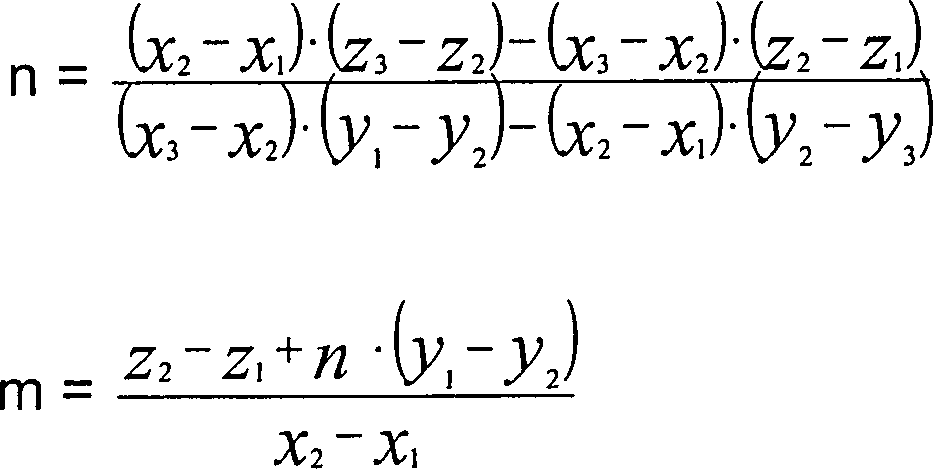
Alle
Dreiecke des kontinuierlichen Modells sind rechtwinklig und hätten, wenn
der rechte Winkel sich im Koordinatenursprung befinden würde, die
Koordinaten
Damit
vereinfachen sich n, m und c zu:
Die
Intensität
I eines beliebig geneigten Dreieckes (beliebiger Wert der Stützstellen)
ist: 
Nach
y und x integriert erhält
man 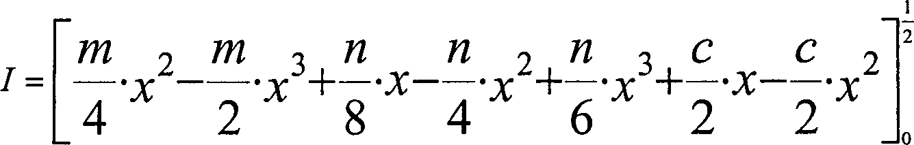
Bei einer Änderung von z3 oder z2 (Stützstellen an den spitzen Winkeln des Dreieckes) erhält man jeweils die doppelte Änderung von n bzw. m, d. h. bei Änderung von z3 oder z2 um den Wert 1 ändert sich der Wert des Integrals um 1/24. Bei einer Änderung von z1 (Stützstelle am rechten Winkel des Dreieckes) um 1 verändert sich der Wert des Integrals um 1/8. Somit kann für eine gewünschte Änderung des Integralwertes direkt die notwendige Änderung des Stützwertes angegeben werden.at a change from z3 or z2 (support points at the acute angles of the triangle) you get the double change from n or m, d. H. at change of z3 or z2 changes by the value 1 the value of the integral is 1/24. When changing z1 (interpolation point at the right angle of the triangle) by 1, the value of the integral changes at 1/8. Thus, for a desired change of the integral value directly the necessary change of the reference value be specified.
Zuerst werden die Stützwerte geändert, die vier Bildelemente beeinflussen. Diese Korrekturen, welche gleichzeitig vier Bildelemente verändern, werden vorgenommen, wenn die Differenzen zwischen den Integralen aller vier Bildelemente und den Intensitäten der entsprechenden Bildelemente das gleiche Vorzeichen haben. Die kleinste Differenz bestimmt dabei die Größe der Korrektur, weil jeweils nur der Fehleranteil korrigiert werden soll, der in allen vier Bildelementen enthalten ist. Wenn die Korrektur dieser Art von Stützwerten über das ganze Bild vorgenommen wurde, werden als nächstes die Stützwerte geändert, die zwei Bildelemente beeinflussen, wobei wiederum die Vorzeichen der Differenzen gleich sein müssen und die kleinste Differenz maßgebend ist. Die jetzt noch verbleibenden Fehler betreffen nur noch einzelne Bildelemente und werden durch Änderung der Mittelpunktsstützstellen korrigiert. Danach ist die Intensitätskonstanz über das gesamte Bild wiederhergestellt.First become the support values changed, affect the four picture elements. These corrections, which simultaneously change four picture elements, are made when the differences between the integrals all four picture elements and the intensities of the corresponding picture elements have the same sign. The smallest difference determines the size of the correction, because in each case only the error portion is to be corrected, which in is included in all four picture elements. If the correction of this Kind of support values about that whole picture was taken, next are the supporting values changed, the two picture elements influence, again the signs the differences must be equal and the smallest difference is. The remaining bugs now only affect individual ones Picture elements and are by change the center points corrected. Thereafter, the intensity constancy is restored throughout the image.
Für jedes
Dreieck innerhalb eines Bildelementes wird nun, wie oben erläutert, die
durch die 3 Stützstellen
(Intensitäten
an den Eckpunkten der Dreiecke) definierte Ebenengleichnung aufgestellt.
Der Resamplingwert (d. h. der zu berechnende Bildwert des Bildelements
Nun wird ein zweites Modell beschrieben, dass z. B. zusätzlich zu dem kontinuierlichen Modell und/oder zusätzlich zu einem anderen Modell für die Verfeinerung der örtlichen Auflösung des Rohbildes verwendet wird. Dieses Modell wird auch als homogenes Modell bezeichnet.Now a second model is described that z. B. in addition to the continuous model and / or in addition to another model for the Refinement of the local resolution of the raw image is used. This model is also called homogeneous Model designates.
Das homogene Modell geht davon aus, dass das abgebildete Gebiet aus homogenen Flächen besteht, d. h. der Bildwert ist innerhalb einer homogenen Fläche konstant. Der Bildwert in einer homogenen Fläche kann dabei, insbesondere abhängig von der Größe der Fläche, ein Extremwert (Maximum oder Minimum) des Bildwertes sein oder er kann ein Durchschnittswert einer größeren Teilfläche des Rohbildes sein. In letzterem Fall ist die homogene Fläche etwa gleich der Fläche der Bildelemente des Rohbildes deren Durchschnittswert der Bildwert ist. Da die Bildelementgrenze im Rohbild in der Regel aber nicht mit der Grenze einer homogenen Fläche übereinstimmt, entstehen im homogenen Modell Bildelemente (d. h. die homogenen Flächen), die als Mischelemente bezeichnet werden können.The homogeneous model assumes that the mapped area homogeneous surfaces exists, d. H. the image value is constant within a homogeneous area. The image value in a homogeneous area can, in particular dependent on the size of the area, a Extreme value (maximum or minimum) of the image value or he can an average of a larger subarea of the Be raw picture. In the latter case, the homogeneous surface is about equal to the area the picture elements of the raw image whose average value the image value is. As the pixel boundary in the raw image is usually not coincides with the boundary of a homogeneous surface, arise in homogeneous model picture elements (ie the homogeneous surfaces), the may be referred to as mixing elements.
Nun wird eine bevorzugte Ausführungsform des homogenen Modells beschrieben: Liegt in einer homogenen Fläche keine exakte Homogenität vor (d. h. sind die Bildwerte der Bildelementen des Rohbildes, die durch die homogene Fläche zusammengefasst werden, nicht exakt gleich), so wird entschieden, ob ein Bildelement ganz zu einer homogenen Fläche gehören soll, oder ob es als Mischelement definiert wird. Diese Entscheidung wird an folgenden eindimensionalen Beispielen erläutert.Now becomes a preferred embodiment of the homogeneous model: Does not lie in a homogeneous area exact homogeneity before (i.e., the image values of the picture elements of the raw image, which are represented by the homogeneous surface summarized, not exactly the same), it is decided whether a picture element is to belong entirely to a homogeneous surface, or whether as a mixing element is defined. This decision will be made on the following one-dimensional Examples explained.
Beispiel
1 ist in
Ein örtliches
Minimum in den Differenzen zeigt ein homogenes Gebiet an, d. h.
die Bildelemente mit den Bildwerten 50 und 48, sowie 41 und 39 werden
im Modell als homogene Flächen
definiert. Da der Bildwert 45 des zwischen diesen beiden homogenen
Flächen
liegenden Bildelementes kein Extremwert ist, wird dieses Bildelement
als Mischelement definiert. D. h. dieses Bildelement wird geteilt
und es wird den neu entstandenen homogenen Flächen jeweils ein Bildwert zugeordnet,
der dem Wert des zur homogenen Fläche gehörenden Nachbarbildelement entspricht.
Z. B. würde
in
Allgemeiner formuliert muss das Mischelement bzw. die aus dem ursprünglichen Bildelement gebildeten neuen Bildelemente (dies sind im zweidimensionalen Fall unter Umständen mehr als zwei Bildelemente) der Bedingung genügen, dass der mit der Fläche gewichtete Durchschnittswert der neuen Bildelemente gleich dem Bildwert des ursprünglichen Bildelementes ist.general formulated the mixing element or from the original Pixel formed new picture elements (these are in the two-dimensional Case under circumstances more than two pixels) satisfy the condition that the area weighted Average value of the new picture elements equal to the picture value of the original Picture element is.
Beispiel
zwei ist in
Die
beiden Beispiele gemäß
Es wird nun beschrieben, wie das homogene Modell im Fall eines realen, zweidimensionalen Rohbildes gebildet wird. Im zweidimensionalen Fall kann ein Unterschied in den Bildwerten zwischen zwei, drei oder sogar vier aneinander angrenzenden homogenen Flächen auftreten, d. h. es können Grenzlinien zwischen zwei homogenen Flächen und Grenzpunkte mit drei oder vier angrenzenden homogenen Flächen auftreten.It will now describe how the homogeneous model in the case of a real, two-dimensional raw image is formed. In two-dimensional Case can be a difference in image values between two, three or even four contiguous homogeneous surfaces occur, d. H. it can Boundary lines between two homogeneous surfaces and boundary points with three or four adjacent homogeneous surfaces.
Findet
der Übergang
nur in einer Richtung (z. B. in Zeilenrichtung oder Spaltenrichtung)
statt, wie es an einer Grenzlinie zwischen zwei homogenen Flächen der
Fall ist, wird der Ort x der Grenzlinie in einem Mischelement zwischen
den homogenen Gebieten wie folgt berechnet:
Dabei ist WM der Bildwert des Mischelements. WN1 ist dabei das linke oder obere Nachbarelement und WN2 das rechte oder untere Nachbarelement.there WM is the image value of the mixing element. WN1 is the left or upper neighbor element and WN2 the right or lower neighbor element.
Auf
diese Weise werden im Ausführungsbeispiel
zunächst
die Grenzlinien für
alle Übergänge zwischen
zwei homogenen Flächen
berechnet, die jeweils zwei Endpunkte auf der Umrandung des Bildelementes besitzen,
wie z. B. das Bildelement
In
In
Zunächst wird
das Mischelement durch Linien vom Mittelpunkt M der Fläche zu den
Endpunkten aufgeteilt.
Wenn
man die Bildwerte der entstandenen homogenen Flächen innerhalb des Mischelements
entsprechend ihren Flächenanteilen
wichtet und so den Durchschnitts-Bildwert berechnet, erhält man in
der Regel einen Durchschnittswert, der nicht mit dem Bildwert des
ursprünglichen
Bildelements übereinstimmt.
Durch Verschiebung des Mittelpunktes M in Richtung des größten Unterschiedes
der Bildwerte der Nachbarelemente wird bei einer bevorzugten Ausführungsform
der Durchschnitts-Bildwert so eingestellt, dass er mit dem Bildwert
des ursprünglichen
Bildelements übereinstimmt.
Ist z. B. die Differenz zwischen den Bildwerten des oberen und unteren
Nachbarelement von Element
Anders
ausgedrückt
wird durch die Verschiebung der Mittelpunkt auf den Punkt
Nun wird aus den Modellen (z. B. für das homogene Modell und das kontinuierliche Modell, oder für eine andere Kombination von Modellen) für jedes Bildelement des ursprünglichen Rohbildes jeweils dasjenige ausgewählt, das die örtliche Abhängigkeit der Bildwerte innerhalb des Bildelementes wahrscheinlich besser (oder, bei mehr als zwei Modellen, am besten) wiedergibt. Bevorzugte Ausführungsbeispiele werden im Folgenden beschrieben.Now gets out of the models (eg for the homogeneous model and the continuous model, or for another Combination of models) for every picture element of the original one Raw image each selected the one that the local dependence the image values within the picture element probably better (or in more than two models, best). Preferred embodiments are described below.
In einem ersten Fall steht zusätzlich zum Rohbild keine weitere Information zur Verfügung, d. h. es liegt insbesondere kein Referenzbild vor. Für diesen Fall wird geprüft, ob verschiedene Modellfunktionen Indizien dafür liefern, dass das jeweilige Modell die örtliche Abhängigkeit der Bildwerte annähernd richtig beschreibt. Insbesondere wird folgende Vorgehensweise vorgeschlagen: für eine Mehrzahl von Orten in dem Rohbild wird jeweils eine Mehrzahl von Funktionen gefittet, d. h. es werden Fitparameter der Funktionen bestimmt. Dabei wird für den Fit mit einer Funktion jeweils ein Teilbereich des Bildes ausgewählt, z. B. ein Bildelement, in dem sich der Ort befindet und zusätzlich einer Anzahl von Bildelementen, die sich in gerader Linie zu dem Bildelement mit dem Ort befinden. Insbesondere werden für denselben Ort verschiedene Teilbereiche des Bildes gewählt und jeweils eine Funktion gefittet. Auf diese Weise können die Verläufe, die sich aus den gefitteten Funktionen ergeben, an dem Ort verglichen werden. Deutliche Unterschiede der sich aus den Funktionen an dem Ort ergebenden Bildwerte deuten daraufhin, dass das jeweilige Modell die örtliche Abhängigkeit der Bildwerte nicht richtig beschreibt und umgekehrt.In a first case is additional to the raw image no further information available, d. H. it is in particular no reference picture before. For this case is being examined whether different model functions provide evidence that the respective Model the local dependence approximating the image values correctly describes. In particular, the following procedure is proposed: for one A plurality of locations in the raw image are each a plurality of Functions fit, d. H. they become fit parameters of the functions certainly. It is for the fit with a function selected in each case a portion of the image, z. B. a picture element in which the place is located and in addition one Number of picture elements that are in a straight line to the picture element to be located with the place. In particular, the same place will be different Subareas of the image selected and each fitted a function. In this way, the gradients, which result from the fit functions compared at the place become. Distinct differences arising from the functions in the place resulting image values indicate that the respective model the local dependence the image values are not correct and vice versa.
Bei
dem nun beschrieben Ausführungsbeispiel
werden an den neun Eckpunkten der Dreiecksflächen des Bildelements
- 1.
Bildelement
41 , Bildelement45 und ein weiteres Bildelement links neben Bildelement45 in derselben Zeile wie Bildelemente41 ,45 . - 2. Bildelement
41 , Bildelement46 und ein weiteres Bildelement rechts neben Bildelement46 in derselben Zeile wie Bildelemente41 ,46 - 3. Bildelement
41 , Bildelement43 und ein weiteres Bildelement oberhalb von Bildelement43 in derselben Spalte wie Bildelemente41 ,43 - 4. Bildelement
41 , Bildelement48 und ein weiteres Bildelement unterhalb von Bildelement48 in derselben Spalte wie Bildelemente41 ,48 .
- 1st picture element
41 , Picture element45 and another picture element to the left of the picture element45 in the same line as picture elements41 .45 , - 2nd picture element
41 , Picture element46 and another picture element to the right of the picture element46 in the same line as picture elements41 .46 - 3rd picture element
41 , Picture element43 and another picture element above picture element43 in the same column as picture elements41 .43 - 4th picture element
41 , Picture element48 and another picture element below picture element48 in the same column as picture elements41 .48 ,
Es wird jeweils die Streuung der Bildwerte an den neun Eckpunkten berechnet.It the scattering of the image values at the nine vertices is calculated in each case.
Eine Möglichkeit der Auswertung ist die folgende: Überschreitet die Streuung (z. B. um den Mittelwert der vier Funktionswerte) einen vorgegebenen Grenzwert, so wird das homogene Modell für dieses Bildelement verwendet. Andernfalls wird das kontinuierliche Modell verwendet.A possibility the evaluation is the following: Exceeds the scatter (z. B. the mean of the four function values) a predetermined Limit, the homogeneous model is used for this pixel. Otherwise, the continuous model is used.
Bei der Verwendung von mehreren Modellen, wird das Modell verwendet, bei dem die vier möglichen Kombinationen die geringste Streuung an den Eckpunkten der Dreiecksflächen erzeugen. Die Streuungen der einzelnen Modelle können dabei auch gewichtet werden.at the use of multiple models, the model is used where the four possible combinations produce the least scattering at the vertices of the triangular surfaces. The scatter of the individual models can also be weighted.
Wenn ein Referenzbild vorhanden ist, so wird diese zusätzliche Information genutzt, um zu entscheiden, welches der zwei oder mehreren Modelle jeweils für ein Bildelement verwendet wird.If a reference image is present, so this is additional Information used to decide which of the two or more Models each for a picture element is used.
Bei
einem konkreten Ausführungsbeispiel
wird ein Quotientenbild berechnet, bei dem sich der Wert an einem
bestimmten Ort das Rohbildes aus der Division des Referenzbildwertes
durch den entsprechenden Ergebniswert des kontinuierlichen Modells
ergibt. Das Referenzbild bezieht sich auf dasselbe Raster wie das
bearbeitete Bild bzw. ist in demselben Orts-Koordinatensystem definiert
die das bearbeitete Bild. Extremwerte in einer 3 × 3 Umgebung
(
Als Extremwert kann ein Bildelement aber auch definiert werden, wenn es gegenüber weniger als acht Nachbarbildelementen, mindestens aber gegenüber zwei Nachbarelementen ein Extremum darstellt. Die Wahrscheinlichkeit eines Resamplingfehlers nimmt dabei mit sinkender Anzahl von Nachbarelementen ab.When Extreme value, a picture element can be defined however also, if it opposite less than eight neighboring pixels, but at least two opposite Neighboring elements represents an extremum. The probability a resampling error decreases with decreasing number of neighboring elements from.
Anhand
von
Werden
mehr als zwei Modelle verwendet, so wird im gezeigten Beispiel die
Aufteilung der Elemente
Insbesondere
nachdem für
jedes Bildelement des Rohbildes entschieden worden ist, welches
Modell die örtliche
Abhängigkeit
der Bildwerte innerhalb des Bildelement am besten beschreibt, steht
die gemischte Modellbeschreibung des Rohbildes fest. In der gemischten
Modellbeschreibung wird die örtliche
Abhängigkeit des
Bildwertes für
jedes Bildelement durch das Modell beschrieben, welches das Beste
für das
Bildelement ist.
Die Berechnung des Resamplingwertes erfolgt nun durch Integration über die jeweilige Fläche der Bildelemente des bearbeiteten Bildes unter Nutzung der Informationen über die Abbildungsfunktion (d. h. die Transformation des Rasters), die den Übergang von dem Rohbild zu dem bearbeiteten Bild beschreibt. Anders ausgedrückt gehen in die Integration für ein bestimmtes Bildelement des bearbeiteten Bildes in der Regel Teilflächen von mehreren Bildelementen des Rohbildes ein. Die Bildwerte dieser Teilflächen werden nach dem Anteil der Teilfläche an der Gesamtfläche gewichtet.The The resampling value is now calculated by integration over the respective area the picture elements of the edited image using the information about the Mapping function (that is, the transformation of the grid) that the transition from the raw image to the edited image. In other words, go into the integration for a certain picture element of the edited picture usually subareas of several pixels of the raw image. The image values of this subareas are weighted according to the proportion of the partial area in the total area.
Claims (3)
Priority Applications (1)
| Application Number | Priority Date | Filing Date | Title |
|---|---|---|---|
| DE200810008707 DE102008008707A1 (en) | 2008-02-11 | 2008-02-11 | Digital image processing method, involves forming mixed model description depending upon verification, and calculating image values of processed images by considering imaging function from result of mixed model description |
Applications Claiming Priority (1)
| Application Number | Priority Date | Filing Date | Title |
|---|---|---|---|
| DE200810008707 DE102008008707A1 (en) | 2008-02-11 | 2008-02-11 | Digital image processing method, involves forming mixed model description depending upon verification, and calculating image values of processed images by considering imaging function from result of mixed model description |
Publications (1)
| Publication Number | Publication Date |
|---|---|
| DE102008008707A1 true DE102008008707A1 (en) | 2009-08-13 |
Family
ID=40847401
Family Applications (1)
| Application Number | Title | Priority Date | Filing Date |
|---|---|---|---|
| DE200810008707 Withdrawn DE102008008707A1 (en) | 2008-02-11 | 2008-02-11 | Digital image processing method, involves forming mixed model description depending upon verification, and calculating image values of processed images by considering imaging function from result of mixed model description |
Country Status (1)
| Country | Link |
|---|---|
| DE (1) | DE102008008707A1 (en) |
Cited By (1)
| Publication number | Priority date | Publication date | Assignee | Title |
|---|---|---|---|---|
| CN111737511A (en) * | 2020-06-17 | 2020-10-02 | 南强智视(厦门)科技有限公司 | Image description method based on self-adaptive local concept embedding |
Citations (2)
| Publication number | Priority date | Publication date | Assignee | Title |
|---|---|---|---|---|
| EP0798664A2 (en) * | 1996-03-28 | 1997-10-01 | Fuji Photo Film Co., Ltd. | Interpolating operation method and apparatus for image signals |
| US5991464A (en) * | 1998-04-03 | 1999-11-23 | Odyssey Technologies | Method and system for adaptive video image resolution enhancement |
-
2008
- 2008-02-11 DE DE200810008707 patent/DE102008008707A1/en not_active Withdrawn
Patent Citations (2)
| Publication number | Priority date | Publication date | Assignee | Title |
|---|---|---|---|---|
| EP0798664A2 (en) * | 1996-03-28 | 1997-10-01 | Fuji Photo Film Co., Ltd. | Interpolating operation method and apparatus for image signals |
| US5991464A (en) * | 1998-04-03 | 1999-11-23 | Odyssey Technologies | Method and system for adaptive video image resolution enhancement |
Cited By (2)
| Publication number | Priority date | Publication date | Assignee | Title |
|---|---|---|---|---|
| CN111737511A (en) * | 2020-06-17 | 2020-10-02 | 南强智视(厦门)科技有限公司 | Image description method based on self-adaptive local concept embedding |
| CN111737511B (en) * | 2020-06-17 | 2022-06-07 | 南强智视(厦门)科技有限公司 | Image description method based on self-adaptive local concept embedding |
Similar Documents
| Publication | Publication Date | Title |
|---|---|---|
| DE10081029B4 (en) | Image editing to prepare a textual analysis | |
| DE102009046114B4 (en) | Method and apparatus for generating a calibrated projection | |
| EP3844943B1 (en) | Method for displaying a model of an environment, control apparatus and vehicle | |
| DE60020887T2 (en) | OPTICAL FLOW AND PICTURE CONSTRUCTION | |
| DE102017010683B4 (en) | Method for automatic restoration of a measured state of a projection system | |
| DE102004004641A1 (en) | Three-dimensional reprojection and rear projection methods and algorithms for performing the same | |
| DE112006001774T5 (en) | Method and product for the detection of irregularities | |
| DE69225264T2 (en) | Minimum difference processor | |
| DE69029429T2 (en) | Binary image reduction process | |
| DE102017114611A1 (en) | Method for generating at least one merged perspective image of a motor vehicle and a surrounding area of the motor vehicle, camera system and motor vehicle | |
| DE102006055758A1 (en) | Camera calibrating method for optical measuring system, involves marking one of cross-over points in checker pattern by position information, which is readable by image processing of images of pattern and has coding of orientation | |
| DE102019110871A1 (en) | Vision system for a vehicle | |
| DE10312535B4 (en) | Method and device for geometrically measuring a material strip | |
| EP1770635B1 (en) | Iterative image interpolation method | |
| DE112017006779T5 (en) | CAMERA SYSTEM INCLUDING OBJECTIVE WITH MAGNIFICATION GRADIENT | |
| WO2002089059A2 (en) | Image processing method | |
| EP3073446B1 (en) | Method for representing the surroundings of a vehicle | |
| EP3685352A1 (en) | Method and device for evaluating images, operating assistance method, and operating device | |
| DE102008008707A1 (en) | Digital image processing method, involves forming mixed model description depending upon verification, and calculating image values of processed images by considering imaging function from result of mixed model description | |
| WO2017093227A1 (en) | Method and device for image correction | |
| EP3465608B1 (en) | Method and device for determining a transfer between two display images, and vehicle | |
| DE102019128781A1 (en) | Method for generating an output signal of a PDAF pixel | |
| DE4404047C1 (en) | Method for influencing the image quality of images supplied by an electronic image recording device | |
| DE102014206246A1 (en) | A method and apparatus for adjusting a three-dimensional projection surface for projecting a plurality of adjacent camera images | |
| EP3391329B1 (en) | Determination of brightness values of virtual pixels |
Legal Events
| Date | Code | Title | Description |
|---|---|---|---|
| OP8 | Request for examination as to paragraph 44 patent law | ||
| R016 | Response to examination communication | ||
| R119 | Application deemed withdrawn, or ip right lapsed, due to non-payment of renewal fee |