DE102007030899B4 - Method and apparatus for generating a discontinuous motion - Google Patents
Method and apparatus for generating a discontinuous motion Download PDFInfo
- Publication number
- DE102007030899B4 DE102007030899B4 DE200710030899 DE102007030899A DE102007030899B4 DE 102007030899 B4 DE102007030899 B4 DE 102007030899B4 DE 200710030899 DE200710030899 DE 200710030899 DE 102007030899 A DE102007030899 A DE 102007030899A DE 102007030899 B4 DE102007030899 B4 DE 102007030899B4
- Authority
- DE
- Germany
- Prior art keywords
- drive
- output
- energy
- energy store
- energy storage
- Prior art date
- Legal status (The legal status is an assumption and is not a legal conclusion. Google has not performed a legal analysis and makes no representation as to the accuracy of the status listed.)
- Expired - Fee Related
Links
Images
Classifications
-
- F—MECHANICAL ENGINEERING; LIGHTING; HEATING; WEAPONS; BLASTING
- F16—ENGINEERING ELEMENTS AND UNITS; GENERAL MEASURES FOR PRODUCING AND MAINTAINING EFFECTIVE FUNCTIONING OF MACHINES OR INSTALLATIONS; THERMAL INSULATION IN GENERAL
- F16H—GEARING
- F16H33/00—Gearings based on repeated accumulation and delivery of energy
Landscapes
- Engineering & Computer Science (AREA)
- General Engineering & Computer Science (AREA)
- Mechanical Engineering (AREA)
- Transmission Devices (AREA)
- Braking Arrangements (AREA)
Abstract
Verfahren zum Wandeln einer kontinuierlichen Bewegung in eine diskontinuierliche Bewegung, bei dem durch einen Antrieb (13) auf einer Antriebsseite (11) eine kontinuierliche Bewegung eines Antriebselementes (16) erzeugt wird, dessen Bewegungsenergie einem Energiespeicher (18) zugeführt wird und von dem Energiespeicher (18) an ein Abtriebselement (20) auf einer Abtriebsseite (12) weitergeleitet wird, dadurch gekennzeichnet, dass das Abtriebselement (20) mittels eines mit dem Abtriebselement verbundenen Bremselementes (21) zeitlich begrenzt und reibschlüssig festgesetzt wird.Method for converting a continuous movement into a discontinuous movement, in which a drive (13) on a drive side (11) generates a continuous movement of a drive element (16) whose kinetic energy is supplied to an energy store (18) and from the energy store ( 18) to an output element (20) on an output side (12) is forwarded, characterized in that the output element (20) by means of a driven element connected to the brake element (21) is limited in time and frictionally fixed.
Description
Die Erfindung betrifft ein Verfahren zum Wandeln einer kontinuierlichen Bewegung in eine diskontinuierliche Bewegung, bei dem durch einen Antrieb auf einer Antriebsseite eine kontinuierliche Bewegung eines Antriebselementes erzeugt wird, dessen Bewegungsenergie einem Energiespeicher zugeführt wird und von dem Energiespeicher an ein Abtriebselement auf einer Abtriebsseite weitergeleitet wird. Ferner betrifft die Erfindung eine Vorrichtung zum Erzeugen einer hochdynamischen Bewegung mit einer Antriebsseite und einer Abtriebsseite, mit einem kontinuierlich arbeitenden Antrieb auf der Antriebsseite, einem Energiespeicher, welcher über den Antrieb aufladbar ist und mit einem über den Energiespeicher beaufschlagbaren Abtriebselement.The invention relates to a method for converting a continuous movement into a discontinuous movement, in which by a drive on a drive side, a continuous movement of a drive element is generated, the kinetic energy is supplied to an energy storage and is forwarded by the energy storage to an output element on a driven side. Furthermore, the invention relates to a device for generating a highly dynamic movement with a drive side and an output side, with a continuously operating drive on the drive side, an energy storage device, which can be charged via the drive and with a loadable via the energy storage output element.
Ein derartiges Verfahren bzw. eine entsprechende Vorrichtung ist aus der
Bei Verfahren und Vorrichtungen zum Erzeugen von linearen beziehungsweise rotatorischen diskontinuierlichen Bewegungen werden für die Beschleunigungsphase und Beschleunigungspitzen große Vorschubkräfte beziehungsweise Drehmomente benötigt. Je höher die Anforderungen an die Dynamik sind, desto größer sind die benötigten Vorschubkräfte beziehungsweise Drehmomente. Hierbei ist von Nachteil, dass die hierzu verwendeten Antriebe und/oder Getriebe neben einer größeren Leistung auch zu einer erhöhten Massenträgheit beitragen, was wiederum zu einer Verringerung der Dynamik führt.In methods and apparatuses for generating linear or rotary discontinuous movements, large feed forces or torques are required for the acceleration phase and acceleration peaks. The higher the demands on the dynamics, the greater are the required feed forces or torques. A disadvantage here is that the drives and / or gearboxes used for this purpose, in addition to greater power, also contribute to increased mass inertia, which in turn leads to a reduction in the dynamics.
Dieser Nachteil kann teilweise dadurch aufgelöst werden, dass die erforderliche Energie zwischengespeichert wird. In diesem Zusammenhang ist es bekannt, die Energie nah am Abtrieb, beispielsweise als Rotationsenergie in einem Schwungrad, zu speichern. Dieses kann kurzzeitig in den Antriebsstrang eingekoppelt werden und somit eine Vorschubbewegung des Abtriebselementes erzeugen. Eine andere Variante eine diskontinuierliche Vorschubbewegung zu realisieren, ergibt sich in bekannter Weise bei Verwendung eines hydraulischen Linearzylinders, der über einen hydraulischen Blasenspeicher versorgt wird. Hierbei ist von Nachteil, dass die Verwendung eines Schwungrades oder eines hydraulischen Blasenspeichers eine vergleichsweise aufwendige Konstruktion notwendig machen.This disadvantage can be partially resolved by caching the required energy. In this connection, it is known to store the energy close to the output, for example as rotational energy in a flywheel. This can be briefly coupled into the drive train and thus generate a feed motion of the output element. Another variant to realize a discontinuous feed movement results in a known manner when using a hydraulic linear cylinder, which is supplied via a hydraulic bladder accumulator. This has the disadvantage that the use of a flywheel or a hydraulic bladder memory make a comparatively complicated construction necessary.
Sofern eine hohe Vorschubkraft und gleichzeitig eine hohe Positioniergenauigkeit gefordert ist, werden üblicherweise elektromechanische Vorschubachsen beispielsweise Kugelgewindetriebe verwendet. Hierbei ist jedoch nachteilig, dass es nicht gelingt, die Spindelsteigung im Sinne einer hohen Dynamik und gleichzeitig einer hohen Laststeifigkeit zu wählen.If a high feed force and at the same time a high positioning accuracy is required, usually electromechanical feed axes, for example ball screws are used. However, it is disadvantageous that it is not possible to choose the spindle pitch in terms of high dynamics and at the same time a high load rigidity.
Darüber hinaus ist es bekannt, Kurvenscheiben, Exzenter oder ein Maltesergetriebe zur Erzeugung von ungleichförmigen linearen Bewegungen zu verwenden. Diese Bewegungswandler erzeugen jedoch positionsabhängig unterschiedliche Geschwindigkeiten in der linearen Vorschubbewegung bei einer ebenfalls ortsabhängigen Steifigkeit. Des Weiteren ist der Einsatz von Zahn- beziehungsweise Flachriemen bekannt, bei denen sowohl durch die Massenträgheiten als auch durch die äußeren Kräfte sich der vergleichsweise nachgiebige Riemen dehnt, wodurch sich eine erhebliche Ungenauigkeit bezüglich der Position des Abtriebselements ergibt.Moreover, it is known to use cams, eccentrics or a Geneva gear to produce non-uniform linear movements. However, these motion transducers generate position-dependent different speeds in the linear feed motion with a likewise location-dependent rigidity. Furthermore, the use of toothed or flat belts is known in which both the inertia and by the external forces, the relatively flexible belt stretches, resulting in a significant inaccuracy with respect to the position of the output element.
Ferner kann ein plötzliches Aufschalten einer äußeren Last bei einem reibungsarm oder reibungsfrei ausgeführtem Bewegungswandler zum Schwingen und/oder Dauerschwingen der antriebsseitigen Elemente führen.Furthermore, a sudden application of an external load in a friction-poor or friction-free motion converter can lead to oscillation and / or fatigue of the drive-side elements.
Hiervon ausgehend liegt der Erfindung das Problem zu Grunde, ein Verfahren und eine konstruktiv einfach aufgebaute Vorrichtung zum Wandeln einer kontinuierlichen Bewegung in eine diskontinuierliche Bewegung anzugeben, wobei abriebsseitig über eine hohe Vorschubkraft eine hohe Dynamik sowie eine hohe Laststeifigkeit und eine hohe Positionsgenauigkeit realisiert wird.On this basis, the invention is based on the problem to provide a method and a structurally simple device for converting a continuous movement in a discontinuous motion, on the abrasion side high momentum and high load rigidity and high positional accuracy is realized on a high feed force.
Zur Lösung dieses Problems ist das erfindungsgemäße Verfahren dadurch gekennzeichnet, dass das Abtriebselement mittels eines mit dem Abtriebselement verbundenen Bremselementes zeitlich begrenzt und reibschlüssig festgesetzt wird. Ferner wird zum Lösen des Problems eine Vorrichtung angegeben, die dadurch gekennzeichnet ist, dass das Abtriebselement mit einem Bremselement verbunden ist, wobei das Bremselement reibschlüssig festsetzbar ist und auf der Abtriebsseite durch eine Leiste reibungsfrei geführt ist.To solve this problem, the inventive method is characterized in that the output element by means of a driven element connected to the brake element is limited in time and frictionally fixed. Furthermore, to solve the problem, a device is specified, which is characterized in that the output element is connected to a brake element, wherein the brake element is frictionally festsetzbar and is guided on the output side by a bar friction.
Über das erfindungsgemäße Verfahren beziehungsweise die erfindungsgemäße Vorrichtung ist es nunmehr möglich gleichzeitig hohe Anforderungen an die abtriebsseitigen Eigenschaften wie beispielsweise einer hohen Vorschubkraft zur Erzeugung einer hohen Dynamik sowie bezüglich einer hohen Positionsgenauigkeit und Laststeifigkeit zu stellen. Somit können die aus dem Stand der Technik bekannten reibungsarmen oder reibungsfreien Bewegungswandler, die jeweils nur für einzelne abtriebsseitige Eigenschaften hohe Anforderungen erfüllen können, durch eine einziges Verfahren beziehungsweise eine einzige Vorrichtung ersetzt werden.By means of the method according to the invention or the device according to the invention, it is now possible at the same time to meet high requirements To provide the output side properties such as a high feed force to produce a high dynamic and with respect to a high positional accuracy and load rigidity. Thus, the known from the prior art low-friction or friction-free motion converter, each of which can meet high requirements only for individual output-side properties, can be replaced by a single method or a single device.
Zudem ist die Konstruktion der erfindungsgemäßen Vorrichtung im Vergleich zu den Bewegungswandlern aus dem Stand der Technik einfach im Aufbau. Auf der Antriebsseite wird über einen Antrieb ein Antriebsstrang angetrieben, auf dem das Antriebselement angeordnet ist. Das Antriebselement ist mit einem beispielsweise mechanischen Energiespeicher verbunden, der sich zwischen der Antriebsseite und der Abtriebsseite befindet. Der Energiespeicher ist mit dem Abtriebselement verbunden, welches beispielsweise auf einer Leiste zusammen mit einem Bremselement geführt ist. Durch diese einfache Konstruktion ergibt sich eine zuverlässige Vorrichtung, die vergleichsweise geringe Kosten bei der Produktion, Wartung und Reparatur erzeugt und zudem sehr leicht auf die individuellen Anforderungen angepasst werden kann.In addition, the construction of the device according to the invention compared to the motion converters of the prior art is simple in construction. On the drive side, a drive train is driven by a drive, on which the drive element is arranged. The drive element is connected to an example mechanical energy storage, which is located between the drive side and the output side. The energy store is connected to the output element, which is guided for example on a bar together with a brake element. This simple construction results in a reliable device that generates comparatively low costs in production, maintenance and repair and also can be easily adapted to individual requirements.
Aufgrund des reibschlüssig festgesetzten Bremselement kann eine hohe Dämpfwirkung erreicht werden. Hierdurch kann die Gefahr des Entstehens von Schwingungen der antriebsseitigen Elemente beim Aufschalten einer äußeren Last bei einem reibungsfreien oder reibungsarmen Bewegungswandler deutlich vermindert werden. Da das Bremselement auf der Abtriebsseite durch eine Leiste reibungsfrei geführt ist, können störende Widerstände bei der abtriebseitigen Bewegung vermieden werden.Due to the frictionally fixed brake element, a high damping effect can be achieved. As a result, the danger of the occurrence of vibrations of the drive-side elements when switching on an external load in a frictionless or low-friction motion converter can be significantly reduced. Since the brake element is guided on the output side by a bar friction, disturbing resistances can be avoided in the output side movement.
Nach einer konkreten konstruktiven Ausgestaltung des erfindungsgemäßen Verfahrens wird die Vorschubenergie des Antriebselementes im Energiespeicher gespeichert, während ein Bremselement des Abtriebselements festgesetzt ist. Somit kann durch Steuerung des Bremselementes eindeutig der Startzeitpunkt festgelegt werden, an dem die Bewegungsenergie des Antriebselementes dem Energiespeicher zugeführt wird. Des Weiteren wird durch die Steuerung des Bremselementes zugleich auch die Lage des Abtriebselementes gesteuert beziehungsweise festgelegt.After a concrete structural design of the method according to the invention the feed energy of the drive element is stored in the energy storage, while a braking element of the output element is fixed. Thus, by controlling the brake element clearly the start time can be determined at which the kinetic energy of the drive element is supplied to the energy storage. Furthermore, the position of the output element is also controlled or determined by the control of the brake element at the same time.
Das Bremselement wird gelöst, wenn eine hochdynamische Vorschubbewegung auf der Abtriebsseite für das Abtriebselement benötigt wird. Die im Energiespeicher gespeicherte Energiemenge wird durch das Lösen des Bremselementes an das Abtriebselement abgegeben. Hierbei ergibt sich eine hochdynamische Vorschubbewegung des Abtriebselements, da das Abtriebselement, vorteilhafterweise nur durch seine Massenträgheit begrenzt, in Vorschubrichtung bewegt wird. Eine neue Position des Abtriebselementes wird durch ein erneutes Schließen des Bremselementes erreicht.The brake element is released when a highly dynamic feed movement is required on the output side for the output element. The amount of energy stored in the energy storage is released by the release of the brake element to the output element. This results in a highly dynamic feed movement of the output element, since the output element, advantageously limited only by its inertia, is moved in the feed direction. A new position of the output element is achieved by re-closing the brake element.
Entsprechend einer Weiterbildung des erfindungsgemäßen Verfahrens wird das Lösen und Schließen des Bremselements über eine Steuerung gesteuert. Durch Steuerung des erneuten Schließens des Bremselementes kann die Zeitspanne zwischen dem Lösen des Bremselementes und dem erneuten Schließen festgelegt werden. Über die Steuerung des Bremselementes kann gleichzeitig die maximal zu erreichende Geschwindigkeit des Abtriebselementes und/oder die zurückgelegte Wegstrecke des Abtriebselementes gesteuert werden. Durch ein nur teilweises Lösen des Bremselementes kann auf die Beschleunigung und/oder die maximal zu erreichende Geschwindigkeit des Abtriebselementes Einfluss genommen werden. Eine auf das Abtriebselement wirkende Bremskraft kann mittels des Bremselementes dosiert werden.According to a development of the method according to the invention, the release and closing of the brake element is controlled by a controller. By controlling the re-closing of the brake element, the period between the release of the brake element and the re-closing can be determined. At the same time, the maximum speed of the output element to be reached and / or the distance traveled by the output element can be controlled via the control of the braking element. By only partially releasing the brake element, it is possible to influence the acceleration and / or the maximum speed of the output element to be reached. A braking force acting on the output element can be metered by means of the braking element.
Bei dem Bremselement der erfindungsgemäßen Vorrichtung handelt es sich vorzugsweise um eine hochdynamisch arbeitende Bewegungsbremse. Vorteilhafterweise handelt es sich bei dieser Leiste um eine Reibleiste, so dass das Bremselement reibschlüssig mit der Reibleiste zusammenwirkt. Hierbei ist vorteilhaft, dass des Bremselement auf der Reibleiste stufenlos, verschiebbar und kraftschlüssig, insbesondere reibschlüssig, festsetzbar ist und vorzugsweise dosierbar ist. Beispielsweise kann eine Bürste als Bremselement dienen, die durch Anstellung der Borsten an die Leiste eine Bremskraft erzeugt.The braking element of the device according to the invention is preferably a highly dynamic working brake. Advantageously, this strip is a friction strip so that the brake element interacts with the friction strip in a frictional engagement. It is advantageous that the braking element on the friction bar stepless, displaceable and non-positive, in particular frictionally engaged, can be fixed and is preferably metered. For example, a brush serve as a braking element, which generates a brake force by employment of the bristles on the bar.
Nach einer alternativen vorteilhaften Ausführungsform ist das Bremselement auf einer Leiste formschlüssig und in diskreten Abständen festsetzbar. Hierzu ist es möglich, das Bremselement derart zu gestalten, dass das Abtriebselement beim Lösen des Bremselementes diskrete und damit eindeutig definierte Sprünge macht. Dies kann beispielsweise durch eine Leiste mit in vorbestimmten Abständen angeordneten Zähnen erreicht werden, in die ein entsprechend ausgestaltetes Bremselement einrastet. Um nun je nach Anforderung verschiedene Abstände bzw. Sprungweiten zu ermöglichen, kann zusätzlich ein Magazin, beispielsweise ein Revolvermagazin, vorgesehen sein, welches eine Anzahl an Leisten mit jeweils unterschiedlich beabstandeten Zähnen bevorratet. Hierdurch ist ein schnelles und einfaches Auswechseln der Leiste für unterschiedliche Anforderungen und/oder Anwendungen gewährleistet.According to an alternative advantageous embodiment, the braking element on a bar is positively and can be fixed at discrete intervals. For this purpose, it is possible to design the brake element such that the output element makes discrete and thus clearly defined jumps when releasing the brake element. This can be achieved for example by a bar with teeth arranged at predetermined intervals, into which a correspondingly configured brake element engages. In order to enable different distances or jump lengths depending on the requirement, a magazine, for example a revolver magazine, can additionally be provided, which stores a number of strips, each with differently spaced teeth. As a result, a quick and easy replacement of the bar for different requirements and / or applications is guaranteed.
Entsprechend einer Weiterbildung der erfindungsgemäßen Vorrichtung ist der Energiespeicher zwischen Antriebsseite und Abtriebsseite angeordnet. Hierdurch ist gewährleistet, dass die Energie der Antriebsseite leicht entnommen werden kann und die gespeicherte Energie möglichst nah am Ort der Nutzbewegung, also der Abtriebsseite, gespeichert wird. Vorzugsweise ist der Energiespeicher ein mechanischer Energiespeicher. Beispielsweise kann der Energiespeicher als eine Feder oder ein Federpaket realisiert sein. Die Federn können Druckfedern und/oder als Zugfedern sein. Durch eine beispielsweise anwendungsabhängige Wahl der Federn, kann die abriebsseitige Dynamik des Abtriebselementes beeinflusst werden. Zudem kann über die Federvorspannung und/oder den Austausch der Feder gegen eine Feder mit einer anderen Federkennlinie die in den Energiespeicher zugeführte Energiemenge gesteuert werden. Dies zusammen mit einem möglicherweise steuerbaren Bremselement ermöglicht die Umsetzung unterschiedlichster abtriebsseitiger Dynamiken.According to a development of the device according to the invention is the energy storage arranged between the drive side and output side. This ensures that the energy of the drive side can be easily removed and the stored energy as close as possible to the location of the Nutzbewegung, ie the output side is stored. The energy store is preferably a mechanical energy store. For example, the energy storage can be realized as a spring or a spring pack. The springs can be compression springs and / or tension springs. By an example application-dependent choice of springs, the abrasion-side dynamics of the output element can be influenced. In addition, via the spring preload and / or the replacement of the spring against a spring with a different spring characteristic, the amount of energy supplied to the energy store can be controlled. This together with a possibly controllable brake element allows the implementation of a wide variety of output-side dynamics.
Alternativ zur Verwendung einer Feder oder eines Federpaketes kann mindestens ein Magnet als Energiespeicher vorgesehen sein. Ein oder mehrere Magnete können so angeordnet sein, dass sie eine Zug- und/oder Druckwirkung erzeugen. So können die abstoßenden Pole bei festgesetztem Bremselement aufeinander zu bewegt werden. Beim Lösen des Bremselementes wird das Abtriebselement aufgrund der sich abstoßenden Pole in Bewegung versetzt.As an alternative to using a spring or a spring assembly, at least one magnet can be provided as an energy store. One or more magnets may be arranged to produce a tensile and / or compressive action. Thus, the repulsive poles can be moved towards each other with fixed braking element. When releasing the brake element, the output element is set in motion due to the repulsive poles.
Darüber hinaus können mechanische Energiespeicher jeglicher Art Verwendung finden, unter anderem auch Gasfedern oder Elastomere. Ferner können auch chemische Energiespeicher sowie vorteilhafterweise hydraulische oder pneumatische Energiespeicher Verwendung finden.In addition, mechanical energy storage of any kind can be used, including gas springs or elastomers. Furthermore, chemical energy storage and advantageously hydraulic or pneumatic energy storage can be used.
Das erfindungsgemäße Verfahren und die erfindungsgemäße Vorrichtung kann als Bewegungswandler zum scheibenweise Spulen von Bandmaterialien, dem so genannten Step-Pack-Verfahren, und/oder für Handhabungsaufgaben, dem so genannten Pick & Place, und/oder bei Vorschubachsen für das Vorschubrundkneten und/oder Werkzeugmaschinen mit gekoppelten Achsen verwendet werden.The method according to the invention and the device according to the invention can be used as motion transducers for the disk-wise winding of strip materials, the so-called step-pack method, and / or for handling tasks, the so-called pick & place, and / or feed axes for the feed rotary kneading and / or machine tools be used with coupled axes.
Beispielsweise bei Werkzeugmaschinen mit verkoppelten Achsen kann die Bearbeitungsrichtung dadurch erzeugt werden, dass eine der sequentiellen Achsen auf Position geregelt und dort unveränderlich ist. Hierbei kann das erfindungsgemäße Verfahren oder die erfindungsgemäße Vorrichtung zum Einsatz kommen, so dass die Kopplung über den Energiespeicher sehr steif ausgeführt wird und das Bremselement zum Festsetzen dient, um die Laststeifigkeit in der entsprechenden Vorschubachsenrichtung zu erhöhen, ohne dass der Vorschubantrieb während der gesamten Bearbeitung in einer Lageregelung betrieben werden muss.For example, in machine tools with coupled axes, the machining direction can be generated by one of the sequential axes being controlled to position and unchangeable there. In this case, the method according to the invention or the device according to the invention can be used, so that the coupling via the energy storage is carried out very stiff and the braking element serves to set to increase the load rigidity in the corresponding feed axis direction, without the feed drive during the entire processing in a position control must be operated.
Ferner sind derartige Anwendungsgebiete geeignet, bei denen variable schwellende oder sogar wechselnde äußere Lasten vorhanden sind, um die entsprechend wirkenden Lastspitzen auf den Antrieb besser ausgleichen zu können. Zudem sind so kleinere Dimensionierungen für die antriebsseitigen Elemente möglich.Furthermore, such applications are suitable in which variable swelling or even changing external loads are present in order to better compensate for the correspondingly acting load peaks on the drive can. In addition, smaller dimensions for the drive-side elements are possible.
Die kontinuierliche antriebsseitige Bewegungsenergie kann je nach Anforderung in eine lineare oder rotatorische diskontinuierliche abtriebsseitige Bewegung umgewandelt werden.The continuous drive-side kinetic energy can be converted into a linear or rotational discontinuous output-side movement as required.
Ein Ausführungsbeispiel der Erfindung wird nachfolgend anhand der Zeichnungen näher erläutert. Es zeigen:An embodiment of the invention will be explained in more detail with reference to the drawings. Show it:
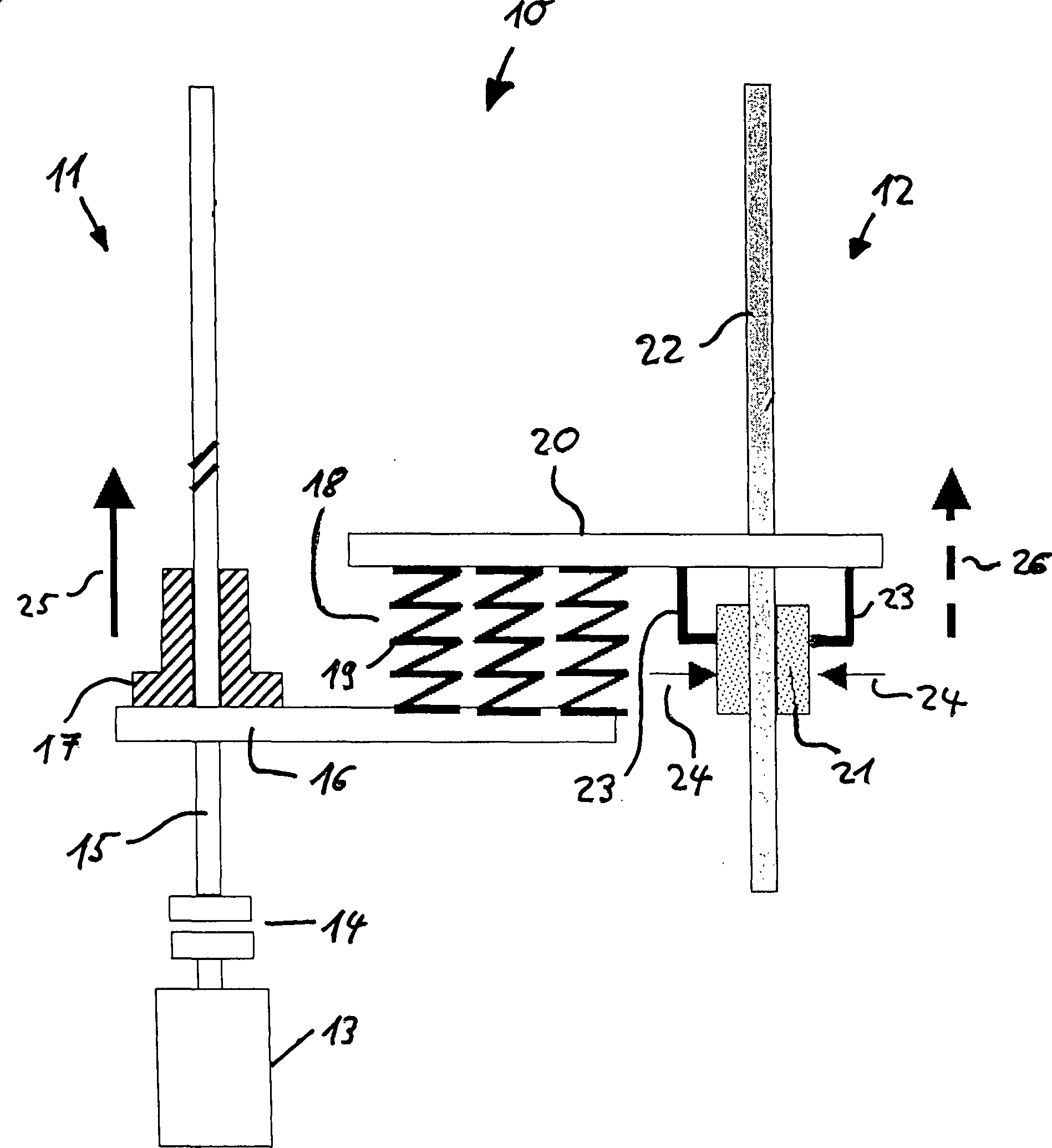
Die
Auf der Spindel
Während das eine Ende des Energiespeichers
Der insoweit beschriebene Bewegungswandler
Über den Antrieb
About the drive
Wird nun das Bremselement
Wie auch
BezugszeichenlisteLIST OF REFERENCE NUMBERS
- 1010
- Bewegungswandlermotion converter
- 1111
- Antriebsseitedriving side
- 1212
- Abtriebsseiteoutput side
- 1313
- Antriebdrive
- 1414
- Kupplungclutch
- 1515
- Spindelspindle
- 1616
- Antriebselementdriving element
- 1717
- Spindelmutterspindle nut
- 1818
- Energiespeicherenergy storage
- 1919
- Federfeather
- 2020
- Abtriebselementoutput element
- 2121
- Bremselementbraking element
- 2222
- Leistestrip
- 2323
- Befestigungsstegfastening web
- 2424
- Pfeilarrow
- 2525
- Pfeilarrow
- 2626
- Pfeilarrow
Claims (12)
Priority Applications (1)
| Application Number | Priority Date | Filing Date | Title |
|---|---|---|---|
| DE200710030899 DE102007030899B4 (en) | 2007-07-03 | 2007-07-03 | Method and apparatus for generating a discontinuous motion |
Applications Claiming Priority (1)
| Application Number | Priority Date | Filing Date | Title |
|---|---|---|---|
| DE200710030899 DE102007030899B4 (en) | 2007-07-03 | 2007-07-03 | Method and apparatus for generating a discontinuous motion |
Publications (2)
| Publication Number | Publication Date |
|---|---|
| DE102007030899A1 DE102007030899A1 (en) | 2009-01-08 |
| DE102007030899B4 true DE102007030899B4 (en) | 2012-09-27 |
Family
ID=40092351
Family Applications (1)
| Application Number | Title | Priority Date | Filing Date |
|---|---|---|---|
| DE200710030899 Expired - Fee Related DE102007030899B4 (en) | 2007-07-03 | 2007-07-03 | Method and apparatus for generating a discontinuous motion |
Country Status (1)
| Country | Link |
|---|---|
| DE (1) | DE102007030899B4 (en) |
Citations (6)
| Publication number | Priority date | Publication date | Assignee | Title |
|---|---|---|---|---|
| DE1190759B (en) * | 1962-02-14 | 1965-04-08 | Helmut Korthaus | Electromotive adjustment device |
| EP0198114B1 (en) * | 1985-04-19 | 1990-05-02 | Rockwell International Corporation | Two speed axle shift apparatus |
| DE10051218A1 (en) * | 2000-10-16 | 2002-04-25 | Zahnradfabrik Friedrichshafen | Change device for gearbox has drive device with electrical actuator drive and energy storage device whose stored energy can be used to operate actuator element(s) |
| DE10104392A1 (en) * | 2001-01-19 | 2002-08-01 | Siemens Ag | Vacuum switch and system and method for its control |
| DE10240166A1 (en) * | 2002-08-30 | 2004-03-18 | Disetronic Licensing Ag | Injection syringe for dispensing insulin to treat diabetes has piston operated by flexible belt which is moved by manually-operated wheel with teeth which cooperate with catches set to give predetermined dose |
| DE10302208A1 (en) * | 2003-01-22 | 2004-07-29 | Klöber GmbH | Chair with quickly adjustable energy storage |
-
2007
- 2007-07-03 DE DE200710030899 patent/DE102007030899B4/en not_active Expired - Fee Related
Patent Citations (6)
| Publication number | Priority date | Publication date | Assignee | Title |
|---|---|---|---|---|
| DE1190759B (en) * | 1962-02-14 | 1965-04-08 | Helmut Korthaus | Electromotive adjustment device |
| EP0198114B1 (en) * | 1985-04-19 | 1990-05-02 | Rockwell International Corporation | Two speed axle shift apparatus |
| DE10051218A1 (en) * | 2000-10-16 | 2002-04-25 | Zahnradfabrik Friedrichshafen | Change device for gearbox has drive device with electrical actuator drive and energy storage device whose stored energy can be used to operate actuator element(s) |
| DE10104392A1 (en) * | 2001-01-19 | 2002-08-01 | Siemens Ag | Vacuum switch and system and method for its control |
| DE10240166A1 (en) * | 2002-08-30 | 2004-03-18 | Disetronic Licensing Ag | Injection syringe for dispensing insulin to treat diabetes has piston operated by flexible belt which is moved by manually-operated wheel with teeth which cooperate with catches set to give predetermined dose |
| DE10302208A1 (en) * | 2003-01-22 | 2004-07-29 | Klöber GmbH | Chair with quickly adjustable energy storage |
Also Published As
| Publication number | Publication date |
|---|---|
| DE102007030899A1 (en) | 2009-01-08 |
Similar Documents
| Publication | Publication Date | Title |
|---|---|---|
| DE10333067B4 (en) | Electric actuator and method of controlling the same | |
| DE2327387B2 (en) | DRIVE FOR HANDLING DEVICES | |
| EP2736150A2 (en) | Linear drive | |
| WO2007042266A1 (en) | Device and method for closing or opening and closing at least one drawer, flap, door, or similar | |
| DE102014001071A1 (en) | Clocked turntable | |
| EP2140978A1 (en) | Impact wrench | |
| WO1994004411A1 (en) | Chain gear with variable transmission ratio and ladder chain | |
| DE102007030899B4 (en) | Method and apparatus for generating a discontinuous motion | |
| DE602004011168T2 (en) | Electromechanical actuator for a clutch of a motor vehicle | |
| DE102011002450A1 (en) | Device for weight compensation of vertically movable spindle head of e.g. numeric controlled milling machine for processing workpiece, has weight compensation mechanism including belt and rollers for reducing produced resilient force | |
| DE102008000601A1 (en) | Reciprocating yarn guide, at a spinner bobbin winder, has paired magnets at the reciprocating rod and machine frame to absorb and deliver energy either side of the direction change dead point | |
| DE102016213596B4 (en) | Method and device for linear and / or rotary positioning | |
| DE102016209427B3 (en) | clutch | |
| EP2687359A1 (en) | Machine and method for improving the precision of a non-linear movement of a machine element | |
| DE10339260A1 (en) | Electric drive for a machining unit on a machine tool or a machining center, has a first motor device to move the machining tool and a spring structure in a load-relieving device | |
| EP2794138A2 (en) | Drive-in device | |
| EP1707310B1 (en) | Process for expanding the belt width of a drive system comprising a motor and coupled vibratory mechanical components, preferably based on ball screw systems and feeder drive for performing such a process | |
| DE102008042235B3 (en) | Stepper drive for stepper drive assembly, has rotor and two drive units cooperating with rotor and gradually driving rotor with help of centrally supplied fluidic energy | |
| EP3449149A1 (en) | Adaptive vibration absorber which is effective in one direction | |
| DE102024129301B3 (en) | Spring drive device with a spring element | |
| DE102010024504B4 (en) | Positioning machine | |
| DE102021129050B3 (en) | Axle device with energy storage arrangement and conveyor system with the axle device | |
| DE102020105590B4 (en) | Energy storage device for storing electrical and/or mechanical energy | |
| DE102018104501A1 (en) | Traction mechanism with firing mechanism | |
| DE102018104498A1 (en) | Traction mechanism with firing mechanism |
Legal Events
| Date | Code | Title | Description |
|---|---|---|---|
| OP8 | Request for examination as to paragraph 44 patent law | ||
| R018 | Grant decision by examination section/examining division | ||
| R020 | Patent grant now final |
Effective date: 20121228 |
|
| R082 | Change of representative |
Representative=s name: ZACCO DR. PETERS UND PARTNER, DE Representative=s name: ZACCO PATENT- UND RECHTSANWALTS GMBH, DE Representative=s name: ZACCO PATENTANWALTS- UND RECHTSANWALTSGESELLSC, DE |
|
| R081 | Change of applicant/patentee |
Owner name: PIWEK, VOLKER, PROF. DR.-ING., DE Free format text: FORMER OWNER: UNIVERSITAET BREMEN, 28359 BREMEN, DE Effective date: 20150504 |
|
| R082 | Change of representative |
Representative=s name: TAPPE, UDO, DIPL.-PHYS. DR.RER.NAT., DE |
|
| R119 | Application deemed withdrawn, or ip right lapsed, due to non-payment of renewal fee |