DE102007028078B4 - Device for feeding electrical energy into a power supply network and DC-DC converter for such a device - Google Patents
Device for feeding electrical energy into a power supply network and DC-DC converter for such a device Download PDFInfo
- Publication number
- DE102007028078B4 DE102007028078B4 DE102007028078A DE102007028078A DE102007028078B4 DE 102007028078 B4 DE102007028078 B4 DE 102007028078B4 DE 102007028078 A DE102007028078 A DE 102007028078A DE 102007028078 A DE102007028078 A DE 102007028078A DE 102007028078 B4 DE102007028078 B4 DE 102007028078B4
- Authority
- DE
- Germany
- Prior art keywords
- circuit
- winding
- inverter
- converter
- storage
- Prior art date
- Legal status (The legal status is an assumption and is not a legal conclusion. Google has not performed a legal analysis and makes no representation as to the accuracy of the status listed.)
- Expired - Fee Related
Links
Classifications
-
- H—ELECTRICITY
- H02—GENERATION; CONVERSION OR DISTRIBUTION OF ELECTRIC POWER
- H02M—APPARATUS FOR CONVERSION BETWEEN AC AND AC, BETWEEN AC AND DC, OR BETWEEN DC AND DC, AND FOR USE WITH MAINS OR SIMILAR POWER SUPPLY SYSTEMS; CONVERSION OF DC OR AC INPUT POWER INTO SURGE OUTPUT POWER; CONTROL OR REGULATION THEREOF
- H02M7/00—Conversion of AC power input into DC power output; Conversion of DC power input into AC power output
- H02M7/42—Conversion of DC power input into AC power output without possibility of reversal
- H02M7/44—Conversion of DC power input into AC power output without possibility of reversal by static converters
- H02M7/48—Conversion of DC power input into AC power output without possibility of reversal by static converters using discharge tubes with control electrode or semiconductor devices with control electrode
- H02M7/53—Conversion of DC power input into AC power output without possibility of reversal by static converters using discharge tubes with control electrode or semiconductor devices with control electrode using devices of a triode or transistor type requiring continuous application of a control signal
- H02M7/537—Conversion of DC power input into AC power output without possibility of reversal by static converters using discharge tubes with control electrode or semiconductor devices with control electrode using devices of a triode or transistor type requiring continuous application of a control signal using semiconductor devices only, e.g. single switched pulse inverters
-
- H—ELECTRICITY
- H02—GENERATION; CONVERSION OR DISTRIBUTION OF ELECTRIC POWER
- H02M—APPARATUS FOR CONVERSION BETWEEN AC AND AC, BETWEEN AC AND DC, OR BETWEEN DC AND DC, AND FOR USE WITH MAINS OR SIMILAR POWER SUPPLY SYSTEMS; CONVERSION OF DC OR AC INPUT POWER INTO SURGE OUTPUT POWER; CONTROL OR REGULATION THEREOF
- H02M7/00—Conversion of AC power input into DC power output; Conversion of DC power input into AC power output
- H02M7/42—Conversion of DC power input into AC power output without possibility of reversal
- H02M7/44—Conversion of DC power input into AC power output without possibility of reversal by static converters
- H02M7/48—Conversion of DC power input into AC power output without possibility of reversal by static converters using discharge tubes with control electrode or semiconductor devices with control electrode
-
- H—ELECTRICITY
- H02—GENERATION; CONVERSION OR DISTRIBUTION OF ELECTRIC POWER
- H02J—CIRCUIT ARRANGEMENTS OR SYSTEMS FOR SUPPLYING OR DISTRIBUTING ELECTRIC POWER; SYSTEMS FOR STORING ELECTRIC ENERGY
- H02J3/00—Circuit arrangements for AC mains or AC distribution networks
- H02J3/38—Arrangements for parallely feeding a single network by two or more generators, converters or transformers
- H02J3/381—Dispersed generators
-
- H02J2101/10—
-
- H02J2101/24—
-
- H—ELECTRICITY
- H02—GENERATION; CONVERSION OR DISTRIBUTION OF ELECTRIC POWER
- H02M—APPARATUS FOR CONVERSION BETWEEN AC AND AC, BETWEEN AC AND DC, OR BETWEEN DC AND DC, AND FOR USE WITH MAINS OR SIMILAR POWER SUPPLY SYSTEMS; CONVERSION OF DC OR AC INPUT POWER INTO SURGE OUTPUT POWER; CONTROL OR REGULATION THEREOF
- H02M1/00—Details of apparatus for conversion
- H02M1/0067—Converter structures employing plural converter units, other than for parallel operation of the units on a single load
- H02M1/007—Plural converter units in cascade
-
- H—ELECTRICITY
- H02—GENERATION; CONVERSION OR DISTRIBUTION OF ELECTRIC POWER
- H02M—APPARATUS FOR CONVERSION BETWEEN AC AND AC, BETWEEN AC AND DC, OR BETWEEN DC AND DC, AND FOR USE WITH MAINS OR SIMILAR POWER SUPPLY SYSTEMS; CONVERSION OF DC OR AC INPUT POWER INTO SURGE OUTPUT POWER; CONTROL OR REGULATION THEREOF
- H02M7/00—Conversion of AC power input into DC power output; Conversion of DC power input into AC power output
- H02M7/42—Conversion of DC power input into AC power output without possibility of reversal
- H02M7/44—Conversion of DC power input into AC power output without possibility of reversal by static converters
- H02M7/48—Conversion of DC power input into AC power output without possibility of reversal by static converters using discharge tubes with control electrode or semiconductor devices with control electrode
- H02M7/483—Converters with outputs that each can have more than two voltages levels
- H02M7/487—Neutral point clamped inverters
-
- Y—GENERAL TAGGING OF NEW TECHNOLOGICAL DEVELOPMENTS; GENERAL TAGGING OF CROSS-SECTIONAL TECHNOLOGIES SPANNING OVER SEVERAL SECTIONS OF THE IPC; TECHNICAL SUBJECTS COVERED BY FORMER USPC CROSS-REFERENCE ART COLLECTIONS [XRACs] AND DIGESTS
- Y02—TECHNOLOGIES OR APPLICATIONS FOR MITIGATION OR ADAPTATION AGAINST CLIMATE CHANGE
- Y02E—REDUCTION OF GREENHOUSE GAS [GHG] EMISSIONS, RELATED TO ENERGY GENERATION, TRANSMISSION OR DISTRIBUTION
- Y02E10/00—Energy generation through renewable energy sources
- Y02E10/50—Photovoltaic [PV] energy
- Y02E10/56—Power conversion systems, e.g. maximum power point trackers
Landscapes
- Engineering & Computer Science (AREA)
- Power Engineering (AREA)
- Dc-Dc Converters (AREA)
- Inverter Devices (AREA)
- Rectifiers (AREA)
- Electrical Discharge Machining, Electrochemical Machining, And Combined Machining (AREA)
- Emergency Protection Circuit Devices (AREA)
Abstract
Vorrichtung zur Einspeisung elektrischer Energie in ein Energieversorgungsnetz (8) mit einem zum Anschluss an einen Gleichspannungsgenerator (1) bestimmten Gleichspannungswandler (2) und einem mit diesem verbundenen, zum Anschluss an das Energieversorgungsnetz (8) bestimmten Wechselrichter (3), der einen bipolaren Spannungszwischenkreis mit zwei in Serie liegenden Kondensatoren (C1, C2) enthält, die an einem mit einem Anschluss des Gleichspannungsgenerators (1) zu verbindenden Erdanschluss (E3) miteinander verbunden sind, wobei der Gleichspannungswandler (2) wenigstens zwei Dioden (D3, D4), einen Schalter und eine Speicherdrossel (16) aufweist, die bei geschlossenem Schalter vom Gleichspannungsgenerator (1) geladen und bei offenem Schalter über die Kondensatoren (C1, C2) und die Dioden (D3, D4) entladen wird, dadurch gekennzeichnet, dass die Speicherdrossel (16) einerseits mit zwei beidseitig der Speicherdrossel in Reihe angeordneten Schaltern (S3, S4) einen ersten, zum Laden der Speicherdrossel (16) bestimmten Stromkreis bildet, der durch Schließen der Schalter (S3, S4) an den Gleichspannungsgenerator (1) angeschlossen ist, während gleichzeitig die sperrenden Dioden (D3,...contraption for feeding electrical energy into a power supply network (8) having a connection for connection to a DC voltage generator (1) DC-DC converter (2) and one connected to this, for Connection to the power grid (8) specific inverter (3), which has a bipolar voltage link with two in series lying capacitors (C1, C2), which at one with a Connection of the DC voltage generator (1) to earth connection to be connected (E3) are interconnected, wherein the DC-DC converter (2) at least two diodes (D3, D4), a switch and a storage choke (16), which when the switch is closed by the DC voltage generator (1) charged and with open switch across the capacitors (C1, C2) and the diodes (D3, D4) is discharged, characterized that the storage throttle (16) on the one hand with two sides of the storage throttle in series switches (S3, S4) a first, for charging the storage choke (16) forms a specific circuit passing through Shut down the switch (S3, S4) connected to the DC voltage generator (1) is while at the same time the blocking diodes (D3, ...
Description
Die Erfindung betrifft eine Vorrichtung der im Oberbegriff des Anspruchs 1 angegebenen Gattung und einen dafür geeigneten Gleichspannungswandler.The The invention relates to a device that in the preamble of claim 1 specified genus and a suitable DC-DC converter.
Zur Einspeisung elektrischer Energie, die mit Gleichspannungsgeneratoren wie z. B. Photovoltaik- oder Brennstoffzellenanlagen erzeugt wird, in ein Wechselstromnetz, insbesondere das öffentliche Energieversorgungsnetz (50/60 Hz), werden Wechselrichter der verschiedensten Art verwendet. Zwischen dem Gleichspannungsgenerator und dem Wechselrichter ist in den meisten Fällen ein Gleichspannungswandler (DC-DC-Steller) vorgesehen, der dem Zweck dient, die vom Gleichspannungsgenerator gelieferte Gleichspannung in eine vom Wechselrichter benötigte bzw. an diesen angepasste Gleichspannung umzuwandeln.to Infeed of electrical energy with DC generators such as B. photovoltaic or fuel cell systems is generated, in an AC network, in particular the public power grid (50/60 Hz), inverters of various types are used. Between the DC generator and the inverter is in most cases a DC-DC converter is provided which serves the purpose of the DC voltage supplied by the DC generator in a required by the inverter or to convert to this adapted DC voltage.
Aus verschiedenen Gründen ist es erwünscht, einen der Ausgänge des Gleichspannungsgenerators zu erden. Der Grund für die gewünschte Erdung besteht einerseits darin, dass es Länder gibt, in denen eine solche Erdung vorgeschrieben ist. Andererseits ergeben sich bei fehlender Erdung verschiedene Nachteile beim Betrieb. Hierzu zählt u. a. das Problem der hochfrequenten Ableitströme. Aufgrund von unvermeidbaren, parasitären Kapazitäten zwischen dem Gleichspannungsgenerator und Erde kann es bei Potentialschwankungen zu nicht unerheblichen Ausgleichsströmen kommen, die ein nicht tolerierbares Sicherheitsrisiko darstellen, daher zum Berührungsschutz bzw. zur Herstellung der elektromagnetischen Verträglichkeit (EMV) aufwendige Überwachungsmaßnahmen mit Hilfe von Fehlerstromsensoren od. dgl. erforderlich machen und nur durch Erdung sicher vermieden können. Außerdem ist bekannt, das Photovoltaik-Generatoren sich sehr unterschiedlich bezüglich Degradation verhalten, je nachdem mit welcher Technologie sie hergestellt wurden. Generatoren mit kristallinen und polykristallinen Zellen oder bestimmten Dünnschichtmodulen werden bevorzugt mit dem negativen Anschluss geerdet, während Rückseiten-Kontaktzellen bevorzugt am positiven Anschluss geerdet werden.Out different reasons is it desirable one of the outputs to ground the DC generator. The reason for the desired grounding On the one hand, there are countries where one is Grounding is prescribed. On the other hand, if missing Grounding various disadvantages during operation. This includes u. a. the Problem of high-frequency leakage currents. Due to unavoidable, parasitic Capacities between the DC voltage generator and earth can be at potential fluctuations come to not insignificant equalizing currents, which is an intolerable Represent safety risk, therefore for protection against contact or for production the electromagnetic compatibility (EMC) extensive monitoring measures od with the help of fault current sensors. Like. Required and can only be safely avoided by grounding. It is also known that photovoltaic generators very different Degradation, depending on the technology with which they were made. Generators with crystalline and polycrystalline cells or specific Become thin-film modules preferably grounded to the negative terminal, while backside contact cells are preferably grounded be grounded positive connection.
Eine Erdung der beschriebenen Art, durch welche die genannten Nachteile vermieden werden könnten, ist ohne weiteres dann möglich, wenn Gleichspannungswandler mit Transformatoren verwendet werden, die eine galvanische Trennung der Gleichspannungsseite von der Wechselspannungsseite herbeiführen. Transformatoren haben aber unabhängig davon, ob Netztransformatoren oder Hochfrequenztransformatoren verwendet werden, u. a. eine Reduzierung des Wirkungsgrades, zum Teil erhebliche Gewichte und Baugrößen und/oder einen zusätzlichen Regelungsaufwand zur Folge, weshalb grundsätzlich transformatorlose Spannungswandler bevorzugt werden. Die üblichen Topologien von transformatorlosen Gleichspannungswandlern machen jedoch die gewünschte Erdung entweder unmöglich, da dies zum Kurzschließen von benötigten Schaltern, Kapazitäten od. dgl. führen würde, oder haben einen erhöhten Schaltungsaufwand und andere Nachteile zur Folge.A Grounding of the type described, through which the mentioned disadvantages could be avoided is readily possible then if DC-DC converters are used with transformers, a galvanic separation of the DC side of the AC side cause. But transformers are independent of whether mains transformers or high-frequency transformers used be, u. a. a reduction in efficiency, sometimes considerable Weights and sizes and / or An additional Regulatory effort result, which is why in principle transformerless voltage converter preferred become. The usual Topologies of transformerless DC-DC converters make however, the desired Earthing either impossible because this is for shorting required switches, capacities od. Like. Lead would, or have an elevated one Circuit complexity and other disadvantages result.
Es
sind daher bereits zahlreiche Versuche unternommen worden, das Auftreten
der genannten Nachteile auf anderem Wege zu vermeiden. Insbesondere
sind Schaltungen bekannt, die dem Zweck dienen, die unerwünschten
Ableitströme
zu reduzieren (z. B.
Weiterhin
ist eine Schaltungsanordnung bekannt (
Daneben
sind auch bereits Schaltungsanordnungen bekannt, mit denen ein Solargenerator trotz
Fehlens eines Transformators einseitig geerdet werden kann. Dadurch
werden kapazitive Ableitströme
prinzipbedingt verhindert. Eine dieser Schaltungsanordnungen (
Schließlich sind
Vorrichtungen bekannt (
Der Gleichspannungswandler dieser bekannten Vorrichtung enthält eine Drossel, zwei Dioden und einen Schalter. Der Erdanschluss des Wechselrichters kann in diesem Fall mit dem negativen Ausgang des Gleichspannungsgenerators verbunden werden. Das wird durch Anwendung einer Speicherdrossel ermöglicht, die aus zwei magnetisch gekoppelten Wicklungen zusammengesetzt ist. Die beiden Wicklungen dieser Speicherdrossel sind an einem Ende derart galvanisch miteinander verbunden, dass einerseits bei geschlossenem Schalter eine der beiden Wicklungen vom Gleichspannungsgenerator und die andere Wicklung aufgrund der magnetischen Kopplung über die erste Wicklung aufgeladen wird und dass andererseits bei offenem Schalter beide Wicklungen über je einen zugeordneten der beiden Kondensatoren und eine zugehörige Diode entladen werden.Of the DC-DC converter of this known device includes a Choke, two diodes and a switch. The ground connection of the inverter can in this case with the negative output of the DC voltage generator get connected. This is done by using a storage choke allows which is composed of two magnetically coupled windings. The two windings of this storage choke are at one end so galvanically connected to each other, that on the one hand when closed Switch one of the two windings from the DC generator and the other winding due to the magnetic coupling over the first winding is charged and that on the other hand when open Switch both windings over each one associated with the two capacitors and an associated diode be discharged.
Dem Vorteil, dass diese Vorrichtung mit vergleichsweise einfachen Mitteln, insbesondere ohne Transformator und mit nur einem Schalter eine Erdung des Gleichspannungsgenerators ermöglicht, steht der Nachteil gegenüber, dass der Erdanschluss nur mit dem negativen Ausgang des Gleichspannungswandlers verbunden werden kann. Weiterhin ist es bei der Vorrichtung nicht möglich, die vom Erdanschluss zum Gleichspannungsgenerator führende Erdleitung auf Fehlerströme zu überwachen, da in dieser Erdleitung prinzipbedingt auch Betriebsströme fließen.the Advantage that this device with comparatively simple means, especially without transformer and with only one switch one Grounding of the DC generator allows the disadvantage across from, that the ground connection only with the negative output of the DC-DC converter can be connected. Furthermore, it is not in the device possible, the ground line leading from the ground connection to the DC generator on fault currents to monitor As a matter of principle, operating currents also flow in this earth line.
Ausgehend von diesem Stand der Technik besteht das technische Problem der Erfindung darin, die Vorrichtung der eingangs bezeichneten Gattung und insbesondere einen dafür geeigneten Gleichspannungswandler so auszubilden, dass eine Erdung des Gleichspannungsgenerators an einem beliebigen Anschluss möglich ist und dies mit vergleichsweise einfachen konstruktiven Mitteln realisiert werden kann.outgoing from this prior art, there is the technical problem of Invention therein, the device of the type described and especially one for that suitable DC-DC converter in such a way that a ground the DC voltage generator is possible at any connection and realized this with relatively simple design means can be.
Gelöst wird dieses Problem erfindungsgemäß mit den kennzeichnenden Merkmalen der Ansprüche 1 und 15.Is solved this problem according to the invention with the characterizing features of claims 1 and 15.
Die Erfindung ermöglicht einen geerdeten Betrieb des Gleichspannungsgenerators durch Anwendung eines Gleichspannungswandlers, der im einfachsten Fall lediglich eine Speicherdrossel, zwei Dioden und zwei Schalter benötigt. Dadurch wird trotz eines nur geringfügig erhöhten Aufwands der Vorteil erzielt, dass der Gleichspannungsgenerator praktisch an einer beliebigen Stelle geerdet werden kann.The Invention allows a grounded operation of the DC voltage generator by application a DC-DC converter, in the simplest case only a storage choke, two diodes and two switches needed. Thereby will be only slightly in spite of one increased Expense the advantage that the DC generator practically can be earthed at any point.
Weitere vorteilhafte Merkmale der Erfindung ergeben sich aus den Unteransprüchen.Further advantageous features of the invention will become apparent from the dependent claims.
Die Erfindung wird nachfolgend in Verbindung mit den beiliegenden Zeichnungen an Ausführungsbeispielen näher erläutert. Es zeigen:The The invention will be described below in conjunction with the accompanying drawings at exemplary embodiments explained in more detail. It demonstrate:
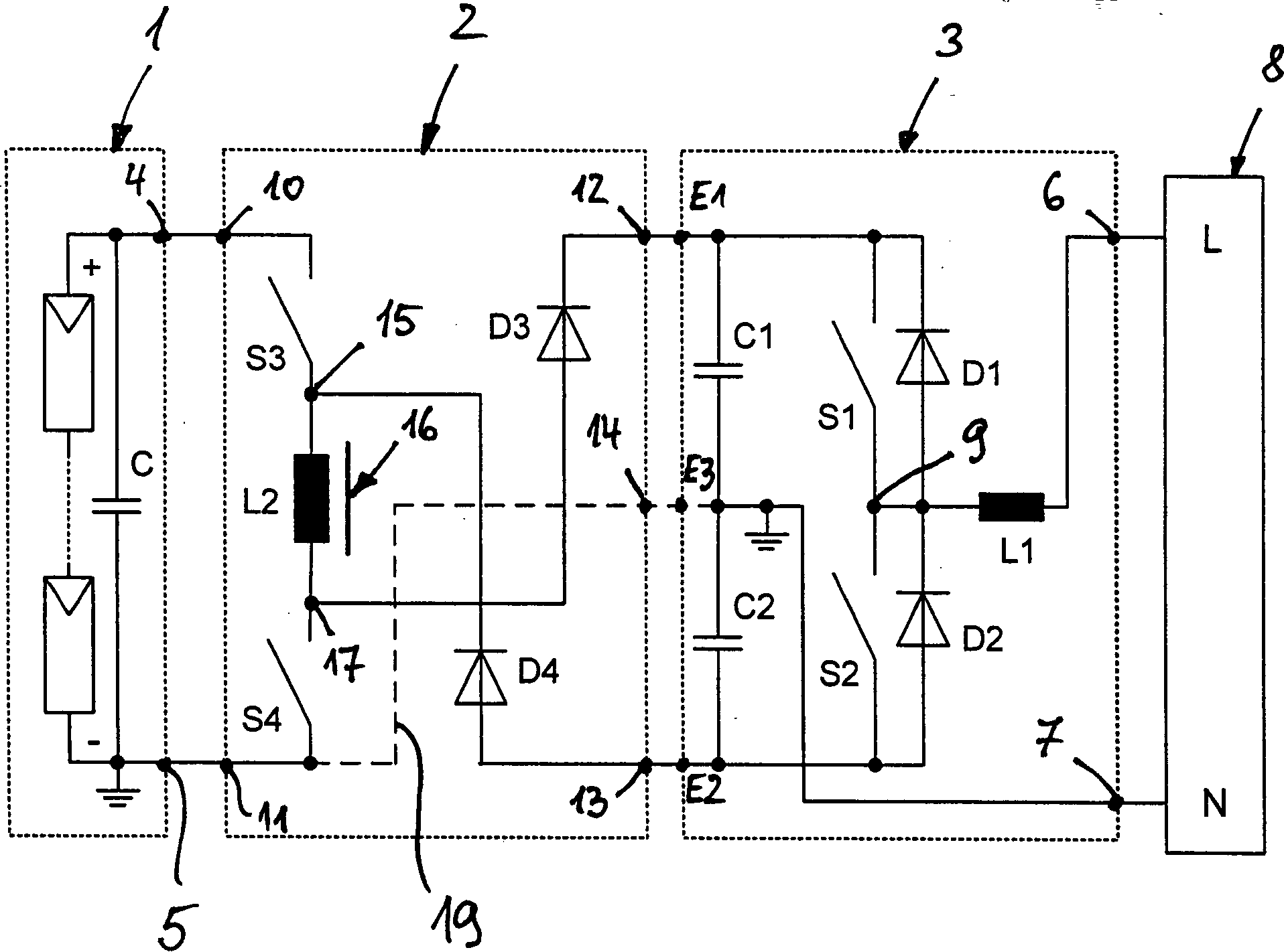
Nach
Ein
im Rahmen der vorliegenden Anmeldung bevorzugter Wechselrichter
Der
Wechselrichter
Vorrichtungen
der beschriebenen Art sind allgemein bekannt (z. B.
Ein
erfindungsgemäßer Gleichspannungswandler
Bei
gleichzeitig geschlossenen Schaltern S3 und S4 wird die Speicherdrossel
When simultaneously closed switches S3 and S4, the storage throttle
Die
Spannungsbelastung der Schalter S3, S4 im geöffneten Zustand ist vergleichsweise gering. Bei
leitenden Dioden D3 und D4 beträgt
die Spannung am Schalter S3 maximal US3 = UC + UC2, wobei UC die
Ausgangsspannung des Gleichspannungsgenerators
Abgesehen
davon bringt der beschriebene Gleichspannungswandler
Die
beschriebene Vorrichtung ist weiterhin sehr flexibel einsetzbar.
Das ergibt sich daraus, dass die Spannungen an C1 und C2 in Abhängigkeit
vom gewählten
Tastverhältnis
für S3
und S4 sowohl größer als
auch kleiner als die Eingangsspannung am Kondensator C sein können. Ist
das Tastverhältnis größer als
0,5, dann arbeitet der Gleichspannungswandler hochsetzend. Ist das
Tastverhältnis
kleiner als 0,5, dann arbeitet der Gleichspannungswandler
Ein
besonders großer
Vorteil der Erfindung ergibt sich schließlich daraus, dass der Erdungspunkt
E3 wahlweise mit dem Eingang
Die Schalter S1 bis S4 sind in bekannter Weise zweckmäßig als Halbleiterschalter ausgebildet, die beim Betrieb mit nicht dargestellten Steuereinheiten (Microcontroller, PWM-Steuerungen usw.) periodisch ein- und ausgeschaltet werden können, wobei die Schaltfrequenz z. B. 16 kHz oder mehr beträgt.The Switches S1 to S4 are useful in a known manner Semiconductor switch formed during operation with not shown Control units (microcontrollers, PWM controllers, etc.) periodically can be switched on and off, where the switching frequency z. B. 16 kHz or more.
Die
Signale für
die Ansteuerung der Schalter S3 und S4 sowie den Stromverlauf in
der Speicherdrossel
Ein
weiteres Ausführungsbeispiel
der Erfindung ist in
Die
erste Wicklung W1 ist wie die Drosselspule
Die erste Wicklung W1
der Speicherdrossel
The first winding W1 of the storage choke
Im
offenen Zustand der Schalter S3, S4 liegen beide Wicklungen W1,
W2 in einem zweiten Serien-Stromkreis, der von einem der Anschlüsse der Wicklung
W1 (Verbindungspunkt
Als
Folge dieser Anordnung ist es möglich, den
Ausgang
Ein
Vorteil der Vorrichtung nach
Nach
einem weiteren, nicht gesondert dargestellten Ausführungsbeispiel
der Erfindung kann die Wicklung W1 der Drosselspule
Die
magnetische Kopplung der Wicklungen W1, W2 in
Ist
eine Erdung am negativen Ausgang
Ist
dagegen eine Erdung am positiven Ausgang des Gleichspannungsgenerators
Bei
Anwendung des Gleichspannungswandlers nach
Obwohl
die bisherige Beschreibung ausschließlich auf den als Halbbrückenwechselrichter ausgebildeten
Wechselrichter
Die
Erfindung ist nicht auf die beschriebenen Ausführungsbeispiele beschränkt, die
auf vielfache Weise abgewandelt werden können. Das gilt insbesondere
auch insoweit, als die Wechselrichter
Claims (16)
Priority Applications (10)
| Application Number | Priority Date | Filing Date | Title |
|---|---|---|---|
| DE102007028078A DE102007028078B4 (en) | 2007-06-15 | 2007-06-15 | Device for feeding electrical energy into a power supply network and DC-DC converter for such a device |
| ES08757931T ES2349394T3 (en) | 2007-06-15 | 2008-04-12 | DEVICE FOR THE POWER SUPPLY OF ELECTRICAL POWER TO A POWER DISTRIBUTION NETWORK AND DC TO DC CONVERTER FOR A DEVICE OF THIS TYPE. |
| EP20080757931 EP2067230B1 (en) | 2007-06-15 | 2008-04-12 | Apparatus for feeding electrical energy into an energy supply system and dc voltage transformer for such an apparatus |
| DE200850001379 DE502008001379D1 (en) | 2007-06-15 | 2008-04-12 | DEVICE FOR FEEDING ELECTRICAL ENERGY IN A POWER SUPPLY NETWORK AND EQUIVALENT VOLTAGE CONVERTER FOR SUCH A DEVICE |
| AT08757931T ATE482507T1 (en) | 2007-06-15 | 2008-04-12 | DEVICE FOR FEEDING ELECTRICAL ENERGY INTO A POWER SUPPLY NETWORK AND DC-VOLTAGE CONVERTER FOR SUCH A DEVICE |
| CN2008800203070A CN101682194B (en) | 2007-06-15 | 2008-04-12 | Apparatus for feeding electrical energy into an energy supply system and DC voltage transformer for such an apparatus |
| PCT/DE2008/000620 WO2009010025A1 (en) | 2007-06-15 | 2008-04-12 | Apparatus for feeding electrical energy into an energy supply system and dc voltage transformer for such an apparatus |
| KR1020097006600A KR101029198B1 (en) | 2007-06-15 | 2008-04-12 | Devices supplying electrical energy to power grids and DC voltage converters for these devices |
| JP2010511483A JP5127001B2 (en) | 2007-06-15 | 2008-04-12 | Device for supplying electrical energy to a power supply network and DC voltage transformer used in said device |
| US12/378,913 US7944091B2 (en) | 2007-06-15 | 2009-02-20 | Apparatus for feeding electrical energy into a power grid and DC voltage converter for such an apparatus |
Applications Claiming Priority (1)
| Application Number | Priority Date | Filing Date | Title |
|---|---|---|---|
| DE102007028078A DE102007028078B4 (en) | 2007-06-15 | 2007-06-15 | Device for feeding electrical energy into a power supply network and DC-DC converter for such a device |
Publications (2)
| Publication Number | Publication Date |
|---|---|
| DE102007028078A1 DE102007028078A1 (en) | 2008-12-24 |
| DE102007028078B4 true DE102007028078B4 (en) | 2009-04-16 |
Family
ID=39753492
Family Applications (2)
| Application Number | Title | Priority Date | Filing Date |
|---|---|---|---|
| DE102007028078A Expired - Fee Related DE102007028078B4 (en) | 2007-06-15 | 2007-06-15 | Device for feeding electrical energy into a power supply network and DC-DC converter for such a device |
| DE200850001379 Active DE502008001379D1 (en) | 2007-06-15 | 2008-04-12 | DEVICE FOR FEEDING ELECTRICAL ENERGY IN A POWER SUPPLY NETWORK AND EQUIVALENT VOLTAGE CONVERTER FOR SUCH A DEVICE |
Family Applications After (1)
| Application Number | Title | Priority Date | Filing Date |
|---|---|---|---|
| DE200850001379 Active DE502008001379D1 (en) | 2007-06-15 | 2008-04-12 | DEVICE FOR FEEDING ELECTRICAL ENERGY IN A POWER SUPPLY NETWORK AND EQUIVALENT VOLTAGE CONVERTER FOR SUCH A DEVICE |
Country Status (9)
| Country | Link |
|---|---|
| US (1) | US7944091B2 (en) |
| EP (1) | EP2067230B1 (en) |
| JP (1) | JP5127001B2 (en) |
| KR (1) | KR101029198B1 (en) |
| CN (1) | CN101682194B (en) |
| AT (1) | ATE482507T1 (en) |
| DE (2) | DE102007028078B4 (en) |
| ES (1) | ES2349394T3 (en) |
| WO (1) | WO2009010025A1 (en) |
Cited By (2)
| Publication number | Priority date | Publication date | Assignee | Title |
|---|---|---|---|---|
| DE102008048841B3 (en) * | 2008-09-25 | 2010-01-28 | Fraunhofer-Gesellschaft zur Förderung der angewandten Forschung e.V. | Isolating circuit for inverter |
| WO2013023936A1 (en) | 2011-08-17 | 2013-02-21 | Sma Solar Technology Ag | Inverter with coupled inductances |
Families Citing this family (32)
| Publication number | Priority date | Publication date | Assignee | Title |
|---|---|---|---|---|
| DE102007029767B3 (en) * | 2007-06-22 | 2008-12-24 | Fraunhofer-Gesellschaft zur Förderung der angewandten Forschung e.V. | inverter |
| EP2148417B1 (en) * | 2008-07-22 | 2018-01-10 | SMA Solar Technology AG | Inverter apparatus for a photovoltaic generator with a plurality of inverters being serially coupled at their input side |
| DE102008063201A1 (en) * | 2008-12-29 | 2010-07-22 | Martin Weinmann | Method and circuit arrangement for feeding the voltage intermediate circuit of an inverter |
| JP2011078290A (en) * | 2009-10-02 | 2011-04-14 | Tabuchi Electric Co Ltd | Power converter and photovoltaic power generation system |
| EP2317635A1 (en) * | 2009-11-02 | 2011-05-04 | ABB Research Ltd | Non-isolated DC-DC converter assembly |
| US8433528B2 (en) * | 2009-12-18 | 2013-04-30 | Rockwell Automation Technologies, Inc. | Ground fault detection system and method |
| EP2367275B2 (en) | 2010-03-18 | 2020-12-23 | MARICI Holdings The Netherlands B.V. | Non-isolated DC - DC converter for solar power plant |
| DE102010060463B4 (en) * | 2010-11-09 | 2013-04-25 | Sma Solar Technology Ag | Circuit arrangement for potential adjustment of a photovoltaic generator and photovoltaic system |
| WO2012067167A1 (en) * | 2010-11-17 | 2012-05-24 | 富士電機株式会社 | Ac-ac converter |
| US8564260B2 (en) * | 2010-12-17 | 2013-10-22 | Qualcomm Incorporated | Dual-stage power conversion |
| US8929114B2 (en) * | 2011-02-24 | 2015-01-06 | Virginia Tech Intellectual Properties, Inc. | Three-level active neutral point clamped zero voltage switching converter |
| JP2014523225A (en) * | 2011-07-08 | 2014-09-08 | エスエムエー ソーラー テクノロジー アーゲー | DC / AC converter, power plant, and method of operation for DC / AC converter |
| DE102012101340B4 (en) | 2012-02-20 | 2015-11-19 | Sma Solar Technology Ag | Protection of photovoltaic modules of a photovoltaic generator against overvoltages to earth |
| DE102012202853A1 (en) * | 2012-02-24 | 2013-08-29 | Robert Bosch Gmbh | Charging circuit for energy storage device of e.g. electric drive system in wind-power plant, has transducer throttle coupled between supply node and supply circuit, and semiconductor switch coupled between supply node and supply circuit |
| DE102012202855A1 (en) * | 2012-02-24 | 2013-08-29 | Robert Bosch Gmbh | Direct voltage tap assembly for energy storage device for electrical propulsion system, has boost converter located between half-bridge circuits based on potential difference between circuits and direct current voltage |
| JP5565527B2 (en) * | 2012-04-10 | 2014-08-06 | 富士電機株式会社 | Power converter |
| UA104964C2 (en) * | 2013-03-18 | 2014-03-25 | Володимир Олексійович Кльосов | Power supply source of electric heating system |
| CN103259433B (en) * | 2013-05-20 | 2015-05-13 | 南京理工大学 | High-frequency isolation type tri-level inverter based on forward converter |
| EP2874303B1 (en) * | 2013-11-15 | 2019-01-02 | Mitsubishi Electric R & D Centre Europe B.V. | DC/AC inverter |
| FR3027151B1 (en) | 2014-10-08 | 2016-12-09 | Schneider Electric Ind Sas | ELECTRICAL CIRCUIT TRANSFORMER AND INSTALLATION COMPRISING SUCH CIRCUIT |
| DE102014225288A1 (en) * | 2014-12-09 | 2016-06-09 | Zf Friedrichshafen Ag | Roll stabilization system for a motor vehicle |
| DE102015105889A1 (en) * | 2015-04-17 | 2016-10-20 | Ge Energy Power Conversion Technology Limited | Switching module and converter with at least one switching module |
| US9812867B2 (en) * | 2015-06-12 | 2017-11-07 | Black Night Enterprises, Inc. | Capacitor enhanced multi-element photovoltaic cell |
| US10381917B2 (en) * | 2017-03-23 | 2019-08-13 | Eaton Intelligent Power Limited | Power converter apparatus and methods using adaptive node balancing |
| US10097109B1 (en) * | 2017-07-19 | 2018-10-09 | Futurewei Technologies, Inc. | Three-level voltage bus apparatus and method |
| JP7021478B2 (en) * | 2017-09-04 | 2022-02-17 | オムロン株式会社 | Photovoltaic system and transducer |
| DE102018201925A1 (en) * | 2018-02-07 | 2019-08-08 | Würth Elektronik eiSos Gmbh & Co. KG | Apparatus for obtaining electrical energy and energy producers with such a device |
| GB201805517D0 (en) * | 2018-04-04 | 2018-05-16 | Rolls Royce Plc | Dc-ac converter and method of dc-ac conversion |
| DE102018212523B4 (en) * | 2018-07-26 | 2021-07-08 | Vitesco Technologies GmbH | Vehicle-side charging circuit |
| US10976762B2 (en) * | 2018-10-26 | 2021-04-13 | Rolls-Royce North American Technologies, Inc. | Control of an electrical power system responsive to sensing a ground fault |
| DE102021108246A1 (en) | 2021-03-31 | 2022-10-06 | KEBA Energy Automation GmbH | Charging station and method of operating a charging station |
| CN113904576B (en) * | 2021-10-26 | 2023-08-08 | 南京信息工程大学 | An integrated boost photovoltaic grid-connected inverter and its control method |
Citations (8)
| Publication number | Priority date | Publication date | Assignee | Title |
|---|---|---|---|---|
| DE19642522C1 (en) * | 1996-10-15 | 1998-04-23 | Dietrich Karschny | Inverter |
| DE19732218C1 (en) * | 1997-07-26 | 1999-03-18 | Dirk Schekulin | Transformerless ac. inverter circuit, for coupling photovoltaic systems or wind generator systems, esp. in the low power range, to current networks |
| DE10221592A1 (en) * | 2002-05-15 | 2003-12-04 | Fraunhofer Ges Forschung | Inverter and method for converting a DC electrical voltage into an AC current |
| DE10225020A1 (en) * | 2002-06-06 | 2003-12-24 | Sma Regelsysteme Gmbh | Circuit arrangement for converting direct to alternating current has power compensation so power or current fed to inverter in one direct voltage branch is equal to that drawn from other branch |
| DE102004030912B3 (en) * | 2004-06-25 | 2006-01-19 | Sma Technologie Ag | Method for converting a direct electrical voltage of a DC voltage source, in particular a photovoltaic DC voltage source into an AC voltage |
| DE102004037446A1 (en) * | 2004-08-02 | 2006-06-01 | Conergy Ag | Transformerless inverter, for the conversion of solar direct current into sinusoidal alternating current for mains supply |
| US20070047277A1 (en) * | 2005-08-29 | 2007-03-01 | Industrial Technology Research Institute | Transformerless power conversion circuit for grid-connected power generation systems |
| WO2007048420A1 (en) * | 2005-10-24 | 2007-05-03 | Conergy Ag | Inverter |
Family Cites Families (7)
| Publication number | Priority date | Publication date | Assignee | Title |
|---|---|---|---|---|
| JP2630221B2 (en) * | 1993-10-08 | 1997-07-16 | 日本電気株式会社 | DC-DC converter |
| JP3520961B2 (en) * | 1998-02-09 | 2004-04-19 | 山洋電気株式会社 | Inverter device |
| JP2000287441A (en) * | 1999-03-31 | 2000-10-13 | Shindengen Electric Mfg Co Ltd | Two output chopper circuit |
| US6275392B1 (en) * | 2000-09-27 | 2001-08-14 | Rockwell Technologies, Llc | Method and apparatus for pre-charge control of VSI |
| JP3888895B2 (en) * | 2001-12-21 | 2007-03-07 | 富士通株式会社 | Positive / negative power source generator and semiconductor device |
| DE10312921A1 (en) * | 2003-03-22 | 2004-10-14 | Sma Regelsysteme Gmbh | Circuit arrangement, additional module and solar system |
| JP4657760B2 (en) * | 2005-02-28 | 2011-03-23 | セイコーインスツル株式会社 | Switching regulator |
-
2007
- 2007-06-15 DE DE102007028078A patent/DE102007028078B4/en not_active Expired - Fee Related
-
2008
- 2008-04-12 EP EP20080757931 patent/EP2067230B1/en not_active Not-in-force
- 2008-04-12 ES ES08757931T patent/ES2349394T3/en active Active
- 2008-04-12 WO PCT/DE2008/000620 patent/WO2009010025A1/en not_active Ceased
- 2008-04-12 KR KR1020097006600A patent/KR101029198B1/en not_active Expired - Fee Related
- 2008-04-12 CN CN2008800203070A patent/CN101682194B/en not_active Expired - Fee Related
- 2008-04-12 DE DE200850001379 patent/DE502008001379D1/en active Active
- 2008-04-12 AT AT08757931T patent/ATE482507T1/en active
- 2008-04-12 JP JP2010511483A patent/JP5127001B2/en not_active Expired - Fee Related
-
2009
- 2009-02-20 US US12/378,913 patent/US7944091B2/en not_active Expired - Fee Related
Patent Citations (8)
| Publication number | Priority date | Publication date | Assignee | Title |
|---|---|---|---|---|
| DE19642522C1 (en) * | 1996-10-15 | 1998-04-23 | Dietrich Karschny | Inverter |
| DE19732218C1 (en) * | 1997-07-26 | 1999-03-18 | Dirk Schekulin | Transformerless ac. inverter circuit, for coupling photovoltaic systems or wind generator systems, esp. in the low power range, to current networks |
| DE10221592A1 (en) * | 2002-05-15 | 2003-12-04 | Fraunhofer Ges Forschung | Inverter and method for converting a DC electrical voltage into an AC current |
| DE10225020A1 (en) * | 2002-06-06 | 2003-12-24 | Sma Regelsysteme Gmbh | Circuit arrangement for converting direct to alternating current has power compensation so power or current fed to inverter in one direct voltage branch is equal to that drawn from other branch |
| DE102004030912B3 (en) * | 2004-06-25 | 2006-01-19 | Sma Technologie Ag | Method for converting a direct electrical voltage of a DC voltage source, in particular a photovoltaic DC voltage source into an AC voltage |
| DE102004037446A1 (en) * | 2004-08-02 | 2006-06-01 | Conergy Ag | Transformerless inverter, for the conversion of solar direct current into sinusoidal alternating current for mains supply |
| US20070047277A1 (en) * | 2005-08-29 | 2007-03-01 | Industrial Technology Research Institute | Transformerless power conversion circuit for grid-connected power generation systems |
| WO2007048420A1 (en) * | 2005-10-24 | 2007-05-03 | Conergy Ag | Inverter |
Cited By (4)
| Publication number | Priority date | Publication date | Assignee | Title |
|---|---|---|---|---|
| DE102008048841B3 (en) * | 2008-09-25 | 2010-01-28 | Fraunhofer-Gesellschaft zur Förderung der angewandten Forschung e.V. | Isolating circuit for inverter |
| DE102008048841B8 (en) * | 2008-09-25 | 2010-06-10 | Fraunhofer-Gesellschaft zur Förderung der angewandten Forschung e.V. | Isolating circuit for inverter |
| WO2013023936A1 (en) | 2011-08-17 | 2013-02-21 | Sma Solar Technology Ag | Inverter with coupled inductances |
| DE102011052768A1 (en) | 2011-08-17 | 2013-02-21 | Sma Solar Technology Ag | Inverters with coupled inductors |
Also Published As
| Publication number | Publication date |
|---|---|
| US20090201706A1 (en) | 2009-08-13 |
| JP2010530206A (en) | 2010-09-02 |
| WO2009010025A8 (en) | 2009-04-23 |
| DE502008001379D1 (en) | 2010-11-04 |
| EP2067230A1 (en) | 2009-06-10 |
| JP5127001B2 (en) | 2013-01-23 |
| US7944091B2 (en) | 2011-05-17 |
| DE102007028078A1 (en) | 2008-12-24 |
| KR101029198B1 (en) | 2011-04-12 |
| CN101682194B (en) | 2013-05-22 |
| ES2349394T3 (en) | 2010-12-30 |
| ATE482507T1 (en) | 2010-10-15 |
| WO2009010025A1 (en) | 2009-01-22 |
| EP2067230B1 (en) | 2010-09-22 |
| KR20090052376A (en) | 2009-05-25 |
| CN101682194A (en) | 2010-03-24 |
Similar Documents
| Publication | Publication Date | Title |
|---|---|---|
| DE102007028078B4 (en) | Device for feeding electrical energy into a power supply network and DC-DC converter for such a device | |
| DE102007028077B4 (en) | Device for feeding electrical energy into a power supply network and DC-DC converter for such a device | |
| EP2030299B1 (en) | Inverter for feeding electrical energy into a power supply system | |
| EP2026457A1 (en) | Inverter with two intermediate circuits | |
| EP2730019B1 (en) | Operating method for an inverter and network fault-tolerant inverter | |
| DE102011051954B4 (en) | Photovoltaic system with bias on the inverter | |
| DE102009028973A1 (en) | DC / DC converter circuit and battery system | |
| EP2026456A1 (en) | Inverter | |
| EP2309639A1 (en) | Reactive power-capable inverter | |
| DE102018008603A1 (en) | Circuit arrangement and method for charging a battery arrangement with a plurality of battery modules | |
| DE102016116630A1 (en) | Method of operating an inverter and inverter | |
| DE4426017C2 (en) | Power supply device, in particular battery charger for electric vehicles or the like | |
| DE102018111154B4 (en) | Charging system | |
| EP3332466A1 (en) | Polarity reverser, inverter having reactive-power capability, and polarity reversing method | |
| EP1870996A1 (en) | Circuit for feeding electric energy in a electric utility grid | |
| EP2523339B1 (en) | Method and apparatus for energy generation by a photovoltaic arrangement with compensation of energy between the branches of the photovoltaic generators | |
| WO2014008976A2 (en) | Charger device for a high-voltage battery of a motor vehicle and motor vehicle | |
| DE202010007787U1 (en) | DC voltage regulator | |
| EP2713499A1 (en) | Energy feed device with symmetrical connection of a direct current source to a grounded star point of a three-phase current network | |
| EP2174408A1 (en) | Inverter | |
| DE102010010781A1 (en) | Inverter and single electric machine arrangement, has bridge circuit added to electronic circuit that raises direct voltage at direct voltage terminals of bridge during switching off of semiconductor switches of bridge for short period | |
| WO2017025489A1 (en) | Potential-shifting half bridge, polarity reverser, inverter having reactive-power capability, and polarity reversing method | |
| DE102011115728A1 (en) | Method for operating an inverter and inverter circuit |
Legal Events
| Date | Code | Title | Description |
|---|---|---|---|
| OP8 | Request for examination as to paragraph 44 patent law | ||
| 8364 | No opposition during term of opposition | ||
| R082 | Change of representative | ||
| R119 | Application deemed withdrawn, or ip right lapsed, due to non-payment of renewal fee |