DE102006029864A1 - Electrode device for electrodascularosis and / or therapy - Google Patents
Electrode device for electrodascularosis and / or therapy Download PDFInfo
- Publication number
- DE102006029864A1 DE102006029864A1 DE102006029864A DE102006029864A DE102006029864A1 DE 102006029864 A1 DE102006029864 A1 DE 102006029864A1 DE 102006029864 A DE102006029864 A DE 102006029864A DE 102006029864 A DE102006029864 A DE 102006029864A DE 102006029864 A1 DE102006029864 A1 DE 102006029864A1
- Authority
- DE
- Germany
- Prior art keywords
- electrode
- electrode device
- fibers
- fiber
- conductivity
- Prior art date
- Legal status (The legal status is an assumption and is not a legal conclusion. Google has not performed a legal analysis and makes no representation as to the accuracy of the status listed.)
- Withdrawn
Links
- 238000002560 therapeutic procedure Methods 0.000 title claims abstract description 7
- 239000000835 fiber Substances 0.000 claims abstract description 65
- 230000000747 cardiac effect Effects 0.000 claims abstract description 6
- 230000000926 neurological effect Effects 0.000 claims abstract description 3
- 239000000463 material Substances 0.000 claims description 11
- 239000007943 implant Substances 0.000 claims description 10
- 239000002344 surface layer Substances 0.000 claims description 9
- 239000002657 fibrous material Substances 0.000 claims description 6
- 239000007787 solid Substances 0.000 claims description 5
- 239000011248 coating agent Substances 0.000 claims description 4
- 238000000576 coating method Methods 0.000 claims description 4
- OKTJSMMVPCPJKN-UHFFFAOYSA-N Carbon Chemical compound [C] OKTJSMMVPCPJKN-UHFFFAOYSA-N 0.000 claims description 3
- 229910052799 carbon Inorganic materials 0.000 claims description 3
- 238000006243 chemical reaction Methods 0.000 claims description 3
- 239000002131 composite material Substances 0.000 claims description 3
- 230000007423 decrease Effects 0.000 claims description 3
- 239000004033 plastic Substances 0.000 claims description 3
- 229920003023 plastic Polymers 0.000 claims description 3
- 238000005234 chemical deposition Methods 0.000 claims description 2
- 238000007598 dipping method Methods 0.000 claims description 2
- 229910052751 metal Inorganic materials 0.000 claims description 2
- 239000002184 metal Substances 0.000 claims description 2
- 238000000034 method Methods 0.000 claims description 2
- 230000003647 oxidation Effects 0.000 claims description 2
- 238000007254 oxidation reaction Methods 0.000 claims description 2
- 238000005289 physical deposition Methods 0.000 claims description 2
- 230000008569 process Effects 0.000 claims description 2
- 239000004065 semiconductor Substances 0.000 claims description 2
- 238000005507 spraying Methods 0.000 claims description 2
- 238000010025 steaming Methods 0.000 claims description 2
- 238000006557 surface reaction Methods 0.000 claims description 2
- 238000007380 fibre production Methods 0.000 claims 1
- 229920000049 Carbon (fiber) Polymers 0.000 description 4
- 239000004917 carbon fiber Substances 0.000 description 4
- 238000001827 electrotherapy Methods 0.000 description 3
- 230000000638 stimulation Effects 0.000 description 3
- 229910000566 Platinum-iridium alloy Inorganic materials 0.000 description 2
- 239000000853 adhesive Substances 0.000 description 2
- 230000001070 adhesive effect Effects 0.000 description 2
- 239000004020 conductor Substances 0.000 description 2
- 238000001514 detection method Methods 0.000 description 2
- 230000005672 electromagnetic field Effects 0.000 description 2
- 238000002001 electrophysiology Methods 0.000 description 2
- 230000007831 electrophysiology Effects 0.000 description 2
- 210000005003 heart tissue Anatomy 0.000 description 2
- 238000010438 heat treatment Methods 0.000 description 2
- 230000006872 improvement Effects 0.000 description 2
- 238000009413 insulation Methods 0.000 description 2
- 239000010410 layer Substances 0.000 description 2
- 238000002595 magnetic resonance imaging Methods 0.000 description 2
- HWLDNSXPUQTBOD-UHFFFAOYSA-N platinum-iridium alloy Chemical class [Ir].[Pt] HWLDNSXPUQTBOD-UHFFFAOYSA-N 0.000 description 2
- 210000001519 tissue Anatomy 0.000 description 2
- 238000003325 tomography Methods 0.000 description 2
- 208000014526 Conduction disease Diseases 0.000 description 1
- 229920000914 Metallic fiber Polymers 0.000 description 1
- BQCADISMDOOEFD-UHFFFAOYSA-N Silver Chemical compound [Ag] BQCADISMDOOEFD-UHFFFAOYSA-N 0.000 description 1
- 206010040844 Skin exfoliation Diseases 0.000 description 1
- 238000002679 ablation Methods 0.000 description 1
- 210000001124 body fluid Anatomy 0.000 description 1
- 239000010839 body fluid Substances 0.000 description 1
- 239000003990 capacitor Substances 0.000 description 1
- 229920001940 conductive polymer Polymers 0.000 description 1
- 230000035618 desquamation Effects 0.000 description 1
- 238000003745 diagnosis Methods 0.000 description 1
- 238000010586 diagram Methods 0.000 description 1
- 230000005670 electromagnetic radiation Effects 0.000 description 1
- 238000005516 engineering process Methods 0.000 description 1
- 230000006698 induction Effects 0.000 description 1
- 229910052741 iridium Inorganic materials 0.000 description 1
- GKOZUEZYRPOHIO-UHFFFAOYSA-N iridium atom Chemical compound [Ir] GKOZUEZYRPOHIO-UHFFFAOYSA-N 0.000 description 1
- 238000002955 isolation Methods 0.000 description 1
- 238000004519 manufacturing process Methods 0.000 description 1
- 150000002739 metals Chemical class 0.000 description 1
- 210000000653 nervous system Anatomy 0.000 description 1
- 230000001537 neural effect Effects 0.000 description 1
- 230000035515 penetration Effects 0.000 description 1
- 229920005594 polymer fiber Polymers 0.000 description 1
- 229920001296 polysiloxane Polymers 0.000 description 1
- 229910052709 silver Inorganic materials 0.000 description 1
- 239000004332 silver Substances 0.000 description 1
- 239000007784 solid electrolyte Substances 0.000 description 1
- 230000009466 transformation Effects 0.000 description 1
- 230000007704 transition Effects 0.000 description 1
Classifications
-
- A—HUMAN NECESSITIES
- A61—MEDICAL OR VETERINARY SCIENCE; HYGIENE
- A61N—ELECTROTHERAPY; MAGNETOTHERAPY; RADIATION THERAPY; ULTRASOUND THERAPY
- A61N1/00—Electrotherapy; Circuits therefor
- A61N1/02—Details
- A61N1/04—Electrodes
- A61N1/05—Electrodes for implantation or insertion into the body, e.g. heart electrode
- A61N1/056—Transvascular endocardial electrode systems
-
- A—HUMAN NECESSITIES
- A61—MEDICAL OR VETERINARY SCIENCE; HYGIENE
- A61N—ELECTROTHERAPY; MAGNETOTHERAPY; RADIATION THERAPY; ULTRASOUND THERAPY
- A61N1/00—Electrotherapy; Circuits therefor
- A61N1/02—Details
- A61N1/08—Arrangements or circuits for monitoring, protecting, controlling or indicating
- A61N1/086—Magnetic resonance imaging [MRI] compatible leads
Landscapes
- Health & Medical Sciences (AREA)
- Heart & Thoracic Surgery (AREA)
- Vascular Medicine (AREA)
- Cardiology (AREA)
- Engineering & Computer Science (AREA)
- Biomedical Technology (AREA)
- Nuclear Medicine, Radiotherapy & Molecular Imaging (AREA)
- Radiology & Medical Imaging (AREA)
- Life Sciences & Earth Sciences (AREA)
- Animal Behavior & Ethology (AREA)
- General Health & Medical Sciences (AREA)
- Public Health (AREA)
- Veterinary Medicine (AREA)
- Electrotherapy Devices (AREA)
- Finger-Pressure Massage (AREA)
Abstract
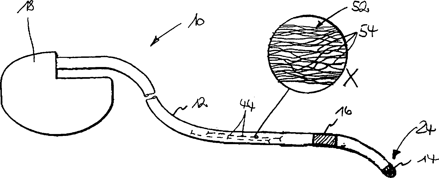
Eine Elektrodeneinrichtung für die kardiologische oder neurologische Elektrodiagnose und/oder -therapie umfasst einen langgestreckten Elektrodenkörper (12), mindestens eine Elektrode (14, 16) in der Nähe des distalen Endes (24) des Elektrodenkörpers (12) und eine Elektrodenleitung (44) für die elektrische Anbindung der Elektrode (14, 16). Die Elektrodenleitung (44) weist einen Faser-Aufbau (52) mit anisotroper Leitfähigkeit derart auf, dass die spezifische Leitfähigkeit der Elektrodenleitung (44) in ihrer Längsrichtung signifikant höher als in ihrer Querrichtung ist.A Electrode device for Cardiac or neurological electrodiagnosis and / or therapy comprises an elongated electrode body (12), at least one Electrode (14, 16) nearby the distal end (24) of the electrode body (12) and an electrode lead (44) for the electrical connection of the electrode (14, 16). The electrode line (44) has a fiber structure (52) with anisotropic conductivity such on that specific conductivity the electrode line (44) in its longitudinal direction significantly higher than in their transverse direction is.
Description
Die Erfindung betrifft eine Elektrodeneinrichtung für die kardiologische oder neurologische Elektrodiagnose und/oder -therapie mit den im Oberbegriff des Patentanspruches 1 angegebenen Merkmalen.The The invention relates to an electrode device for cardiac or neurological Electrodiagnosis and / or therapy with the in the preamble of claim 1 specified characteristics.
Derartige
Elektrodeneinrichtungen sind beispielsweise aus der
Übliche Elektrodeneinrichtungen, wie sie aus dem Stand der Technik in vielfältigen Ausführungsformen bekannt sind, verwenden als Elektrodenleitungen massive, metallische Zuleitungen oder Litzen, bei denen die Einzelleiter nicht voneinander isoliert sind. Ein Patient, der eine derartige Elektrodeneinrichtung implantiert hat, ist von der schonenden Magnetresonanz-Diagnostik mit Hilfe von Kernspintomographen ausgeschlossen, da sich derartige metallische Elektrodenleitungen in extrem starken elektromagnetischen Feldern, wie sie in Magnetresonanz-Tomographen (MRT) auftreten, aufgrund der fließenden Induktionsströme oder die umgebenden Gewebeschichten durch an den Leitungsenden austretende Induktionsströme stark erwärmen können.Usual electrode devices, as known from the prior art in various embodiments, use solid, metallic leads as electrode leads or strands in which the individual conductors are not isolated from each other. A patient implanting such an electrode device has help from gentle magnetic resonance diagnostics excluded by magnetic resonance imaging, since such metallic Electrode leads in extremely strong electromagnetic fields, as they occur in magnetic resonance imaging (MRI) due the flowing one induced currents or the surrounding tissue layers by exiting at the ends of the conduit induced currents warm up a lot can.
Aus
der oben genannten
Insoweit liegt der Erfindung die Aufgabe zugrunde, eine Elektrodeneinrichtung für die Elektrodiagnose und/oder -therapie auf den Betrieb im MR-Tomographen hin zu optimieren.in this respect The invention is based on the object, an electrode device for the Electro-diagnosis and / or therapy for operation in the MR tomograph to optimize.
Diese Aufgabe wird laut Kennzeichnungsteil des Anspruches 1 durch einen Faser-Aufbau der Elektrodenleitung mit anisotroper Leitfähigkeit gelöst. Die spezifische Leitfähigkeit der Elektrodenleitung ist dabei in ihrer Längsrichtung signifikant höher als in ihrer Querrichtung. „Signifikant höher" bedeutet in diesem Zusammenhang, dass die Anisotropie der spezifischen Leitfähigkeit abgestimmt auf die Dimensionen der Elektrodenleitung selbst und der Stärke und dem Charakter des bei der MR-Tomographie zum Einsatz kommenden Magnetfeldes so gewählt sein soll, dass bei einem Einsatz der Elektrodeneinrichtung bei der MR-Tomographie keine physiologisch bedenkliche Erwärmung der Elektrodenleitung stattfindet.These Task is according to the characterizing part of claim 1 by a Fiber structure of the electrode line with anisotropic conductivity solved. The specific conductivity The electrode line is significantly higher in its longitudinal direction than in their transverse direction. "Significant higher "means in this Related to that the anisotropy of the specific conductivity matched to the dimensions of the electrode line itself and the strength and the character of the magnetic field used in MR tomography be so chosen is intended that when using the electrode device in MR tomography no physiologically harmful heating of the electrode line takes place.
Gemäß einem bevorzugten Ausführungsbeispiel kann der Faser-Aufbau aus einem festen Faserverbund beispielsweise auf der Basis eines verstreckten Faserbündels oder aus einem Bündel von Einzelfasern bestehen. Letztere können durch lose aneinanderliegende, verdrillte, geflochtene, verklebte, verpresste oder anderweitig gebündelte Filamente gebildet sein.According to one preferred embodiment For example, the fiber structure can be made of a solid fiber composite on the basis of a stretched fiber bundle or a bundle of individual fibers consist. The latter can by loosely fitting, twisted, braided, glued, compressed or otherwise bundled Be formed filaments.
Für die Realisierung der anisotropen Leitfähigkeit der Elektrodenleitung ist es besonders effektiv, wenn die Fasern in sich eine anisotrope, in Längsrichtung signifikant höhere Leitfähigkeit als in Querrichtung aufweisen. Dazu kann aufgrund des Herstellungsprozesses jede Einzelfaser so ausgelegt sein, dass ihre Leitfähigkeit aufgrund der intrinsischen Materialeigenschaften radial von innen nach außen graduell abnimmt. Einfacher realisierbar ist jedoch ein Faseraufbau, bei dem eine hochohmige bis isolierende Oberflächenschicht der Faser hergestellt wird. Diese Oberflächenschicht kann durch eine Stoffumwandlung des Fasermaterials selbst gebildet sein und besteht beispielsweise aus bei der Umwandlung von Polymerfasern in Karbonfasern durch starkes Erhitzen entstehende, hochohmige Residuen. Alternativ dazu kann eine vom eigentli chen Fasermaterial separate Oberflächenschicht durch eine Oberflächenreaktion, wie insbesondere eine Oxidation, des Fasermaterials gebildet werden.For the realization the anisotropic conductivity The electrode line is particularly effective when the fibers in itself an anisotropic, in the longitudinal direction significantly higher conductivity as in the transverse direction. This may be due to the manufacturing process Each individual fiber should be designed so that its conductivity due to the intrinsic material properties radially from the inside outward gradually decreases. However, it is easier to implement a fiber structure, in which a high-resistance to insulating surface layer of the fiber produced becomes. This surface layer can be formed by a material transformation of the fiber material itself and consists, for example, in the conversion of polymer fibers in carbon fibers, due to strong heating, high-resistance residuals. Alternatively, one of the eigentli chen fiber material separate surface layer through a surface reaction, as in particular an oxidation of the fiber material are formed.
Prozesstechnisch ebenfalls leicht beherrschbar ist ein Aufbringen einer gesonderten Beschichtung als hochohmige bis isolierende Oberflächenschicht. Diese Beschichtung kann durch Tauchen, Besprühen, Bedampfen und physikalischer bzw. chemischer Abscheidung angebracht werden.process technology, also easy to control is an application of a separate Coating as a high-resistance to insulating surface layer. This coating can be applied by dipping, spraying, steaming and physical or chemical deposition are attached.
Grundsätzlich eignen sich für die Fasern der Elektrodeneinrichtung alle ausreichend leitfähigen und mechanisch in entsprechende Form bringbare Materialien, wie Kohlenstoff, Metalle, leitende Kunststoffe (wie aus Kondensatoren mit festem Elektrolyt bekannt) oder Halbleitermaterialien.In principle, all materials which are sufficiently conductive and can be mechanically brought into appropriate form, such as carbon, metals, conductive plastics (such as capacitors with a solid electrolyte), are suitable for the fibers of the electrode device known) or semiconductor materials.
Weitere Merkmale, Einzelheiten und Vorteile der Erfindung ergeben sich aus der nachfolgenden Beschreibung, in der ein Ausführungsbeispiel anhand der beigefügten Zeichnungen näher erläutert wird. Es zeigen:Further Features, details and advantages of the invention will become apparent the following description, in which an embodiment with reference to the accompanying drawings is explained in more detail. Show it:
In
Der
Elektrodenkörper
Die
Tip- und Ringelektrode
In
den Elektrodenkörper
Wie
aus der mit X bezeichneten, ausschnittsweisen Detailvergrößerung in
Wie
aus
Bei
den in
Eine
weitere Ausführungsform
der Erfindung gemäß
In
einem weiteren Ausführungsbeispiel
gemäß
Ein
weiteres Ausführungsbeispiel
verwendet als passive Fasern solche, die nicht über die gesamte Elektrodenleitungslänge durchgängig sind.
Der Faseraufbau hat dabei eine filzartige Struktur mit Vorzugsrichtung
in Längsachse
der Elektrodenleitung
Claims (21)
Priority Applications (5)
| Application Number | Priority Date | Filing Date | Title |
|---|---|---|---|
| DE102006029864A DE102006029864A1 (en) | 2006-06-28 | 2006-06-28 | Electrode device for electrodascularosis and / or therapy |
| US11/742,366 US8082042B2 (en) | 2006-06-28 | 2007-04-30 | Electrode device for electrodiagnosis and/or electrotherapy |
| DE502007000428T DE502007000428D1 (en) | 2006-06-28 | 2007-06-01 | Electrode device for electrodiagnosis and / or therapy |
| EP07010843A EP1872825B1 (en) | 2006-06-28 | 2007-06-01 | Electrode device for electro-diagnosis and/or electrotherapy |
| AT07010843T ATE422372T1 (en) | 2006-06-28 | 2007-06-01 | ELECTRODE DEVICE FOR ELECTRODIAGNOSIS AND/OR THERAPY |
Applications Claiming Priority (1)
| Application Number | Priority Date | Filing Date | Title |
|---|---|---|---|
| DE102006029864A DE102006029864A1 (en) | 2006-06-28 | 2006-06-28 | Electrode device for electrodascularosis and / or therapy |
Publications (1)
| Publication Number | Publication Date |
|---|---|
| DE102006029864A1 true DE102006029864A1 (en) | 2008-01-03 |
Family
ID=38567134
Family Applications (2)
| Application Number | Title | Priority Date | Filing Date |
|---|---|---|---|
| DE102006029864A Withdrawn DE102006029864A1 (en) | 2006-06-28 | 2006-06-28 | Electrode device for electrodascularosis and / or therapy |
| DE502007000428T Active DE502007000428D1 (en) | 2006-06-28 | 2007-06-01 | Electrode device for electrodiagnosis and / or therapy |
Family Applications After (1)
| Application Number | Title | Priority Date | Filing Date |
|---|---|---|---|
| DE502007000428T Active DE502007000428D1 (en) | 2006-06-28 | 2007-06-01 | Electrode device for electrodiagnosis and / or therapy |
Country Status (4)
| Country | Link |
|---|---|
| US (1) | US8082042B2 (en) |
| EP (1) | EP1872825B1 (en) |
| AT (1) | ATE422372T1 (en) |
| DE (2) | DE102006029864A1 (en) |
Families Citing this family (5)
| Publication number | Priority date | Publication date | Assignee | Title |
|---|---|---|---|---|
| DE102008010188A1 (en) * | 2008-02-20 | 2009-08-27 | Biotronik Crm Patent Ag | Method for producing an insulation tube and method for producing an electrode |
| EP2522387B1 (en) | 2011-05-10 | 2017-05-31 | BIOTRONIK SE & Co. KG | Implantable medical lead |
| US9026841B1 (en) * | 2014-09-09 | 2015-05-05 | Belkin International, Inc. | Coordinated and device-distributed detection of abnormal network device operation |
| US10063439B2 (en) | 2014-09-09 | 2018-08-28 | Belkin International Inc. | Coordinated and device-distributed detection of abnormal network device operation |
| EP3067090A1 (en) * | 2015-03-10 | 2016-09-14 | BIOTRONIK SE & Co. KG | Electrode device for electrodiagnosis and/or electrotherapy and implant comprising an electrode device |
Citations (5)
| Publication number | Priority date | Publication date | Assignee | Title |
|---|---|---|---|---|
| DD263239A1 (en) * | 1987-08-17 | 1988-12-28 | Akad Wissenschaften Ddr | STIMULATION AND DETECTOR ELECTRODE |
| US5265579A (en) * | 1992-09-21 | 1993-11-30 | Ferrari R Keith | X-ray transparent monitoring electrode and method for making |
| US5938597A (en) * | 1995-05-04 | 1999-08-17 | Stratbucker; Robert A. | Electrocardiograph bioelectric interface system and method of use |
| DE10217828A1 (en) * | 2002-04-16 | 2003-10-30 | Biotronik Mess & Therapieg | electrode line |
| WO2005053555A1 (en) * | 2003-12-01 | 2005-06-16 | Biotronik Crm Patent Ag | Electrode catheter for the electrotherapy of cardiac tissue |
Family Cites Families (12)
| Publication number | Priority date | Publication date | Assignee | Title |
|---|---|---|---|---|
| FR1557087A (en) * | 1967-12-15 | 1969-02-14 | ||
| US4198991A (en) | 1978-05-17 | 1980-04-22 | Cordis Corporation | Cardiac pacer lead |
| FR2446001A1 (en) | 1979-01-03 | 1980-08-01 | Cardiofrance Co | Electrical conductor for cardiac pacemaker - has inner conducting sleeve surrounded by carbon fibres inside outer flexible insulating sleeve |
| US5554176A (en) | 1986-05-15 | 1996-09-10 | Telectronics Pacing Systems, Inc. | Implantable electrode and sensor lead apparatus |
| EP0312495A3 (en) | 1987-10-16 | 1989-08-30 | Institut Straumann Ag | Electrical cable for carrying out at least one stimulation and/or measurement in a human or animal body |
| US5411527A (en) * | 1989-05-03 | 1995-05-02 | Intermedics, Inc. | Difibrillation electrodes and implantation |
| US5433730A (en) | 1989-05-03 | 1995-07-18 | Intermedics, Inc. | Conductive pouch electrode for defibrillation |
| US5683444A (en) | 1995-12-11 | 1997-11-04 | Huntley; Steve | Composite electrode |
| US5824026A (en) * | 1996-06-12 | 1998-10-20 | The Spectranetics Corporation | Catheter for delivery of electric energy and a process for manufacturing same |
| US20040064175A1 (en) * | 2002-09-30 | 2004-04-01 | Lessar Joseph F. | Implantable medical device lead conductor having integral biostable in-situ grown oxide insulation and process for forming |
| US7877150B2 (en) | 2004-03-30 | 2011-01-25 | Medtronic, Inc. | Lead electrode for use in an MRI-safe implantable medical device |
| WO2005116702A2 (en) | 2004-05-24 | 2005-12-08 | Suave Lobodzinski | Biological signal sensor on a body surface |
-
2006
- 2006-06-28 DE DE102006029864A patent/DE102006029864A1/en not_active Withdrawn
-
2007
- 2007-04-30 US US11/742,366 patent/US8082042B2/en not_active Expired - Fee Related
- 2007-06-01 AT AT07010843T patent/ATE422372T1/en not_active IP Right Cessation
- 2007-06-01 EP EP07010843A patent/EP1872825B1/en active Active
- 2007-06-01 DE DE502007000428T patent/DE502007000428D1/en active Active
Patent Citations (5)
| Publication number | Priority date | Publication date | Assignee | Title |
|---|---|---|---|---|
| DD263239A1 (en) * | 1987-08-17 | 1988-12-28 | Akad Wissenschaften Ddr | STIMULATION AND DETECTOR ELECTRODE |
| US5265579A (en) * | 1992-09-21 | 1993-11-30 | Ferrari R Keith | X-ray transparent monitoring electrode and method for making |
| US5938597A (en) * | 1995-05-04 | 1999-08-17 | Stratbucker; Robert A. | Electrocardiograph bioelectric interface system and method of use |
| DE10217828A1 (en) * | 2002-04-16 | 2003-10-30 | Biotronik Mess & Therapieg | electrode line |
| WO2005053555A1 (en) * | 2003-12-01 | 2005-06-16 | Biotronik Crm Patent Ag | Electrode catheter for the electrotherapy of cardiac tissue |
Also Published As
| Publication number | Publication date |
|---|---|
| ATE422372T1 (en) | 2009-02-15 |
| DE502007000428D1 (en) | 2009-03-26 |
| EP1872825B1 (en) | 2009-02-11 |
| US20080004680A1 (en) | 2008-01-03 |
| EP1872825A3 (en) | 2008-01-23 |
| EP1872825A2 (en) | 2008-01-02 |
| US8082042B2 (en) | 2011-12-20 |
Similar Documents
| Publication | Publication Date | Title |
|---|---|---|
| EP1691704B1 (en) | Electrode line for the electrotherapy of cardiac tissue | |
| EP1923094B1 (en) | Electrode catheter for intervention purposes | |
| EP1923095B1 (en) | Electrode for intervention purposes | |
| DE60310194T2 (en) | FILTERING OF COUPLED ELECTROMAGNETIC SIGNALS ON SUPPLIES | |
| DE112010001330T5 (en) | MRI-compatible implantable connection electrode interface | |
| EP2359898A2 (en) | Implantable element with means for reducing a flux density | |
| EP3756725A1 (en) | Implantable electrode line with braided conductors | |
| EP2110154B1 (en) | Device for reducing the interference susceptibility of elongate impants | |
| EP1872825B1 (en) | Electrode device for electro-diagnosis and/or electrotherapy | |
| DE102020100121A1 (en) | Implantable electrode with a stub line | |
| DE69820889T2 (en) | Management for medical purposes | |
| EP1285678B1 (en) | Single electrode lead for pacemaker systems | |
| EP2985053A1 (en) | Implantable electrical line | |
| EP2446922B1 (en) | Implantable conductors with additional, field decoupling conductors | |
| EP2110156B1 (en) | Field decoupling element for use with an implantable lead and implantable medical device | |
| EP2465569B1 (en) | Implantable device | |
| EP2848282B1 (en) | Implantable device | |
| EP2478933A2 (en) | Implantable device | |
| EP2465573B1 (en) | Implantable device | |
| EP2283894B1 (en) | Stimulation electrode lead | |
| EP2985054B1 (en) | Implantable device with electrical filter | |
| EP2853288B1 (en) | Implantable device and production method for an implantable device | |
| DE4032153C2 (en) | ||
| EP2143463A1 (en) | Shock electrode line | |
| DE102007022333A1 (en) | Electrode e.g. nuero-stimulation electrode, for intervention purposes, has casing surrounding supply line, where materials of pole and casing are made such that materials contain conductive particles in concentration embedded in matrix |
Legal Events
| Date | Code | Title | Description |
|---|---|---|---|
| OM8 | Search report available as to paragraph 43 lit. 1 sentence 1 patent law | ||
| 8139 | Disposal/non-payment of the annual fee |