DE102005060967B4 - Method and device for setting up a trajectory of a robot device - Google Patents
Method and device for setting up a trajectory of a robot device Download PDFInfo
- Publication number
- DE102005060967B4 DE102005060967B4 DE102005060967A DE102005060967A DE102005060967B4 DE 102005060967 B4 DE102005060967 B4 DE 102005060967B4 DE 102005060967 A DE102005060967 A DE 102005060967A DE 102005060967 A DE102005060967 A DE 102005060967A DE 102005060967 B4 DE102005060967 B4 DE 102005060967B4
- Authority
- DE
- Germany
- Prior art keywords
- trajectory
- coordinates
- robot
- projected
- points
- Prior art date
- Legal status (The legal status is an assumption and is not a legal conclusion. Google has not performed a legal analysis and makes no representation as to the accuracy of the status listed.)
- Expired - Fee Related
Links
- 238000000034 method Methods 0.000 title claims abstract description 48
- 238000001514 detection method Methods 0.000 claims description 31
- 230000003287 optical effect Effects 0.000 claims description 27
- 238000012545 processing Methods 0.000 claims description 17
- 238000013461 design Methods 0.000 claims description 2
- 230000006870 function Effects 0.000 description 12
- 230000006978 adaptation Effects 0.000 description 6
- 239000000853 adhesive Substances 0.000 description 3
- 230000001070 adhesive effect Effects 0.000 description 3
- 230000008859 change Effects 0.000 description 3
- 238000004519 manufacturing process Methods 0.000 description 3
- 238000004088 simulation Methods 0.000 description 3
- 238000013459 approach Methods 0.000 description 2
- 230000001419 dependent effect Effects 0.000 description 2
- 239000011521 glass Substances 0.000 description 2
- 230000002452 interceptive effect Effects 0.000 description 2
- 238000003754 machining Methods 0.000 description 2
- 239000003550 marker Substances 0.000 description 2
- 238000012986 modification Methods 0.000 description 2
- 230000004048 modification Effects 0.000 description 2
- 230000009466 transformation Effects 0.000 description 2
- 238000000844 transformation Methods 0.000 description 2
- 238000007792 addition Methods 0.000 description 1
- 238000004026 adhesive bonding Methods 0.000 description 1
- 230000002411 adverse Effects 0.000 description 1
- 238000003491 array Methods 0.000 description 1
- 230000009286 beneficial effect Effects 0.000 description 1
- 230000008901 benefit Effects 0.000 description 1
- 230000005540 biological transmission Effects 0.000 description 1
- 239000003086 colorant Substances 0.000 description 1
- 238000005520 cutting process Methods 0.000 description 1
- 230000007547 defect Effects 0.000 description 1
- 239000003292 glue Substances 0.000 description 1
- 238000003384 imaging method Methods 0.000 description 1
- 239000004973 liquid crystal related substance Substances 0.000 description 1
- 238000012423 maintenance Methods 0.000 description 1
- 238000005457 optimization Methods 0.000 description 1
- 238000001454 recorded image Methods 0.000 description 1
- 230000008672 reprogramming Effects 0.000 description 1
- 239000007787 solid Substances 0.000 description 1
- 238000012800 visualization Methods 0.000 description 1
- 238000003466 welding Methods 0.000 description 1
Classifications
-
- B—PERFORMING OPERATIONS; TRANSPORTING
- B25—HAND TOOLS; PORTABLE POWER-DRIVEN TOOLS; MANIPULATORS
- B25J—MANIPULATORS; CHAMBERS PROVIDED WITH MANIPULATION DEVICES
- B25J9/00—Programme-controlled manipulators
- B25J9/16—Programme controls
- B25J9/1656—Programme controls characterised by programming, planning systems for manipulators
- B25J9/1671—Programme controls characterised by programming, planning systems for manipulators characterised by simulation, either to verify existing program or to create and verify new program, CAD/CAM oriented, graphic oriented programming systems
-
- G—PHYSICS
- G05—CONTROLLING; REGULATING
- G05B—CONTROL OR REGULATING SYSTEMS IN GENERAL; FUNCTIONAL ELEMENTS OF SUCH SYSTEMS; MONITORING OR TESTING ARRANGEMENTS FOR SUCH SYSTEMS OR ELEMENTS
- G05B19/00—Programme-control systems
- G05B19/02—Programme-control systems electric
- G05B19/18—Numerical control [NC], i.e. automatically operating machines, in particular machine tools, e.g. in a manufacturing environment, so as to execute positioning, movement or co-ordinated operations by means of programme data in numerical form
- G05B19/41—Numerical control [NC], i.e. automatically operating machines, in particular machine tools, e.g. in a manufacturing environment, so as to execute positioning, movement or co-ordinated operations by means of programme data in numerical form characterised by interpolation, e.g. the computation of intermediate points between programmed end points to define the path to be followed and the rate of travel along that path
- G05B19/4103—Digital interpolation
-
- G—PHYSICS
- G05—CONTROLLING; REGULATING
- G05B—CONTROL OR REGULATING SYSTEMS IN GENERAL; FUNCTIONAL ELEMENTS OF SUCH SYSTEMS; MONITORING OR TESTING ARRANGEMENTS FOR SUCH SYSTEMS OR ELEMENTS
- G05B19/00—Programme-control systems
- G05B19/02—Programme-control systems electric
- G05B19/42—Recording and playback systems, i.e. in which the programme is recorded from a cycle of operations, e.g. the cycle of operations being manually controlled, after which this record is played back on the same machine
-
- G—PHYSICS
- G05—CONTROLLING; REGULATING
- G05B—CONTROL OR REGULATING SYSTEMS IN GENERAL; FUNCTIONAL ELEMENTS OF SUCH SYSTEMS; MONITORING OR TESTING ARRANGEMENTS FOR SUCH SYSTEMS OR ELEMENTS
- G05B2219/00—Program-control systems
- G05B2219/30—Nc systems
- G05B2219/35—Nc in input of data, input till input file format
- G05B2219/35347—Replace tool by light emitter, operator checks light path on workpiece
-
- G—PHYSICS
- G05—CONTROLLING; REGULATING
- G05B—CONTROL OR REGULATING SYSTEMS IN GENERAL; FUNCTIONAL ELEMENTS OF SUCH SYSTEMS; MONITORING OR TESTING ARRANGEMENTS FOR SUCH SYSTEMS OR ELEMENTS
- G05B2219/00—Program-control systems
- G05B2219/30—Nc systems
- G05B2219/36—Nc in input of data, input key till input tape
- G05B2219/36458—Teach only some points, for playback interpolation between points
-
- G—PHYSICS
- G05—CONTROLLING; REGULATING
- G05B—CONTROL OR REGULATING SYSTEMS IN GENERAL; FUNCTIONAL ELEMENTS OF SUCH SYSTEMS; MONITORING OR TESTING ARRANGEMENTS FOR SUCH SYSTEMS OR ELEMENTS
- G05B2219/00—Program-control systems
- G05B2219/30—Nc systems
- G05B2219/37—Measurements
- G05B2219/37017—Calibration of vision system, set correct attidude of sensor to workpiece
-
- G—PHYSICS
- G05—CONTROLLING; REGULATING
- G05B—CONTROL OR REGULATING SYSTEMS IN GENERAL; FUNCTIONAL ELEMENTS OF SUCH SYSTEMS; MONITORING OR TESTING ARRANGEMENTS FOR SUCH SYSTEMS OR ELEMENTS
- G05B2219/00—Program-control systems
- G05B2219/30—Nc systems
- G05B2219/37—Measurements
- G05B2219/37053—Optical triangulation
-
- G—PHYSICS
- G05—CONTROLLING; REGULATING
- G05B—CONTROL OR REGULATING SYSTEMS IN GENERAL; FUNCTIONAL ELEMENTS OF SUCH SYSTEMS; MONITORING OR TESTING ARRANGEMENTS FOR SUCH SYSTEMS OR ELEMENTS
- G05B2219/00—Program-control systems
- G05B2219/30—Nc systems
- G05B2219/40—Robotics, robotics mapping to robotics vision
- G05B2219/40002—Camera, robot follows direction movement of operator head, helmet, headstick
-
- G—PHYSICS
- G05—CONTROLLING; REGULATING
- G05B—CONTROL OR REGULATING SYSTEMS IN GENERAL; FUNCTIONAL ELEMENTS OF SUCH SYSTEMS; MONITORING OR TESTING ARRANGEMENTS FOR SUCH SYSTEMS OR ELEMENTS
- G05B2219/00—Program-control systems
- G05B2219/30—Nc systems
- G05B2219/40—Robotics, robotics mapping to robotics vision
- G05B2219/40523—Path motion planning, path in space followed by tip of robot
Landscapes
- Engineering & Computer Science (AREA)
- Physics & Mathematics (AREA)
- General Physics & Mathematics (AREA)
- Automation & Control Theory (AREA)
- Robotics (AREA)
- Mechanical Engineering (AREA)
- Computing Systems (AREA)
- Theoretical Computer Science (AREA)
- Human Computer Interaction (AREA)
- Manufacturing & Machinery (AREA)
- Numerical Control (AREA)
- Manipulator (AREA)
Abstract
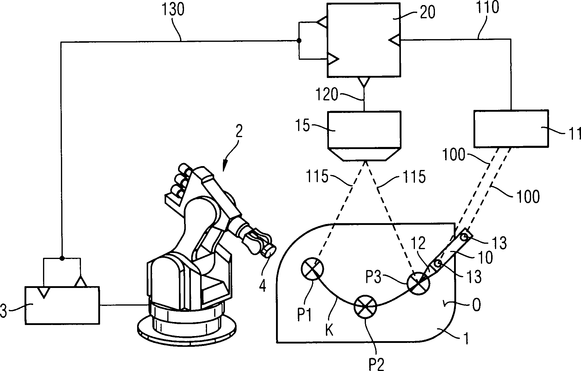
Die Erfindung betrifft ein Verfahren zum Einrichten einer Bahnkurve für eine Robotereinrichtung. Ein Werkstück 1 mit wenigstens einer zu bearbeitenden Oberfläche O wird im Arbeitsbereich der Robotervorrichtung 2 angeordnet. Eine Zeigereinrichtung 10 wird an einer Mehrzahl von Stützpunkten P1, P2, ... auf der zu bearbeitenden Oberfläche O positioniert. Die Koordinaten der Stützpunkte P1, P2, ... werden durch Erfassen der zugehörigen Koordinaten der Zeigereinrichtung 10 festgelegt. Zwischen jeweils zwei benachbarten Stützpunkten P1, P2, ... wird automatisch gemäß einem vorbestimmten Algorithmus interpoliert, um die Bahnkurve K festzulegen. Die Bahnkurve K wird auf die zu bearbeitende Oberfläche O projiziert.The The invention relates to a method for establishing a trajectory for one Robotic device. A workpiece 1 with at least one surface to be machined O becomes in the working area the robot device 2 is arranged. A pointing device 10 is on a plurality of bases P1, P2, ... positioned on the surface to be machined O. The coordinates of bases P1, P2, ... are detected by detecting the associated coordinates of the pointing device 10 set. Between every two neighboring bases P1, P2, ... is automatically set according to a interpolated predetermined algorithm to set the trajectory K. The trajectory K is projected onto the surface O to be processed.
Description
Die vorliegende Erfindung betrifft ein Verfahren zum Einrichten einer Bahnkurve einer Robotervorrichtung. Insbesondere ist das Verfahren für eine interaktive Einrichtung durch einen Bediener geeignet. Ferner wird eine Vorrichtung zum Durchführen des erfindungsgemäßen Verfahrens geschaffen.The The present invention relates to a method for setting up a Trajectory of a robot device. In particular, the method for one interactive device suitable by an operator. Furthermore, will a device for performing the method according to the invention created.
Die US 2005/0149231 A1 als nächst liegender Stand der Technik beschreibt ein Verfahren und ein System zum Programmieren eines industriellen Roboters. Eine Zeigereinrichtung wird von einem Benutzer geführt und die Punkte auf einem zu bearbeitenden Objekt punktiert, die Teil eines Pfades eines Roboterwerkzeugs sein sollen. Die Position und Orientierung wird mit einer Verfolgungseinheit erfasst. Ein Pfadsimulator simuliert den momentanen Roboterpfad basierend auf der Liste von erfassten Punkten. Auf einem Headup-Display wird der simulierte Pfad zusammen mit einer Abbildung des zu bearbeitenden Objekts als virtual reality image dargestellt.The US 2005/0149231 A1 as next The prior art describes a method and a system for programming an industrial robot. A pointing device is managed by a user and punctures the points on an object to be edited, the Be part of a path of a robot tool. The position and orientation is detected with a tracking unit. One Path simulator simulates the current robot path based on the list of detected points. On a headup display is the simulated path along with an illustration of the one being edited Object represented as a virtual reality image.
Aus dem Artikel "A Human-Robot Interface Using an Interactive Hand Pointer that Projects a Mark in the Work Space" erschienen in Proceedings of the 2001 IEEE International Conference on Robotics and Automation, 24–28 April 2000, Band 1, S. 589–595 beschreibt ein System für eine Mensch-Roboter-Schnittstelle. Die Position einer Hand eines Betreibers wird erfasst und mittels eines LCD-Projektors an die erfasste Position eine Markierung projiziert.Out the article "A Human Robot Interface Using Interactive Hand Pointer that Projects a Mark in the Work Space " in Proceedings of the 2001 IEEE International Conference on Robotics and Automation, 24-28 April 2000, Volume 1, pp. 589-595 describes a system for a human-robot interface. The Position of a hand of an operator is detected and by means of a LCD projector the detected position projects a marker.
Die
Die WO 03/032129 A2 beschreibt ein Verfahren und System zum Visualisieren von Oberflächenfehlern durch optisches Projizieren eines topografischen Musters auf die Oberfläche.The WO 03/032129 A2 describes a method and system for visualization from surface defects optically projecting a topographic pattern on the surface.
Der Artikel "Laser-Based Guidance of Multiple Mobile Robots" erschienen in "Proceedings of the 2001 IEEE/ASME Int. Conference on Advanced Intelligent Mechatronics", 8.–12. Juli 2001, S. 410–415 beschreibt ein optisches Führungssystem für Roboter.Of the Article "Laser-Based Guidance of Multiple Mobile Robots "published in" Proceedings of the 2001 IEEE / ASME Int. Conference on Advanced Intelligent Mechatronics ", July 8-12, 2001, pp. 410-415 describes a optical guidance system for robots.
Die Herstellung einer Vielzahl von Produkten erfolgt heute zweckmäßigerweise durch Roboter und von Ihnen geführte Werkzeuge. Bevor ein Roboter erstmals zur Herstellung einer neuen Serie von Werkstücken verwendet werden kann, müssen dessen Bewegungsabläufe programmiert werden. Dies erfordert einen relativ hohen Zeitaufwand. Der Zeitaufwand mag bei der Herstellung von Produkten in großer Stückzahl noch gerechtfertigt sein, ist aber bei der Bearbeitung von Einzelstücken oder der Herstellung von kleinen Serien häufig nicht mehr vertretbar. Notwendige Programmänderungen bei Abwandlungen der Produkte, auftretenden Störungen des Roboters und dessen Wartung bedingen oft eine aufwendige Änderung der Programmierung. Nachteilig ist auch, dass die Programmierung nur von einem eingewiesenen Fachmann durchgeführt werden kann.The Production of a variety of products is done today conveniently through robots and guided by you Tools. Before a robot for the first time to produce a new Series of workpieces used can, must its movements be programmed. This requires a relatively high amount of time. The time spent may still be high in the manufacture of large numbers of products be justified, but is in the processing of individual pieces or the production of small series often no longer justifiable. Necessary program changes with modifications of the products, occurring disturbances of the robot and its Maintenance often requires a costly change in programming. adversely is also that programming only by a trained professional carried out can be.
Die Verfahren zur Programmierung können in zwei Typen unterschieden werden. In einem ersten Typ (offline) werden mittels eines Robotermodells die Bewegungsabläufe ohne den Roboter programmiert. Für die offline Programmierung sind dreidimensionale Modelle der zu bearbeitenden Werkstücke, der Arbeitsumgebung und des Roboters notwendig. Eine Erstellung und Anpassung dieser Daten erfordert einen erheblichen Aufwand. Ferner sind in der Regel Optimierungsschritte des programmierten Bewegungsablaufs am realen Roboter unvermeidbar, da sich meist die dreidimensionalen Modelle und die von ihnen abgebildete Realität unterscheiden. In dem zweiten Typ (online) wird direkt der Roboter programmiert. Eine Mehrzahl von Stützpunkten werden von dem Roboter manuell gesteuert angefahren und die Posen des Roboters abgespeichert. Die Auswahl der Stützpunkte und die manuelle Steuerung des Roboters bedarf jedoch eines speziell ausgebildeten Personals.The Method of programming can be distinguished into two types. In a first type (offline) become by a robot model, the movements without programmed the robot. For offline programming are three-dimensional models too machining workpieces, the working environment and the robot necessary. A creation and adaptation of this data requires a considerable effort. Furthermore, as a rule, optimization steps of the programmed are Movement on real robot unavoidable, since usually the distinguish three-dimensional models and the reality depicted by them. In the second type (online), the robot is programmed directly. A plurality of bases are controlled by the robot manually controlled and the poses of the robot. Selection of bases and manual control However, the robot requires a specially trained staff.
Ansätze zur
Vereinfachung der anfänglichen
Programmierung bestehen darin, mittels einer Kamera die Arbeitsumgebung
und des Werkstücks
aufzunehmen und auf einem Monitor oder Datenbrille darzustellen. Der
Darstellung des Werkstücks
wird eine simulierte Bahnkurve des Roboters überlagert. Ein entsprechendes Verfahren
ist aus
Die
Eine Aufgabe der vorliegenden Erfindung ist es, ein Verfahren und eine Vorrichtung zu schaffen, welche eine einfache und verbesserte Einrichtung von Bahnkurven eines Roboters ermöglichen.A Object of the present invention is to provide a method and a Device to create a simple and improved device enable trajectories of a robot.
Die vorgenannte Aufgabe wird durch das erfindungsgemäße Verfahren nach Patentanspruch 1 und die Vorrichtung nach Patentanspruch 16 gelöst.The The aforementioned object is achieved by the method according to the invention 1 and the device according to claim 16 solved.
Das erfindungsgemäße Verfahren sieht folgende Schritte vor. Ein Werkstück mit wenigstens einer zu bearbeitenden Oberfläche wird im Arbeitsbereich der Robotervorrichtung angeordnet. Eine Zeigereinrichtung wird an einer Mehrzahl von Stützpunkten auf der zu bearbeitenden Oberfläche positioniert. Die Koordinaten der Stützpunkte werden durch Erfassen der zugehörigen Koordinaten der Zeigereinrichtung festgelegt. Zwischen jeweils zwei benachbarten Stützpunkten wird automatisch gemäß einem vorbestimmten Algorithmus interpoliert, um die Bahnkurve festzulegen. Die Bahnkurve wird auf die zu bearbeitende Oberfläche projiziert.The inventive method provides the following steps. A workpiece with at least one to be machined surface is placed in the working area of the robotic device. A pointing device becomes at a plurality of bases on the surface to be processed positioned. The coordinates of the vertices are detected by the associated Coordinates of the pointing device set. Between every two neighboring bases will automatically according to one interpolated predetermined algorithm to set the trajectory. The trajectory is projected onto the surface to be processed.
Ein Vorteil des erfindungsgemäßen Verfahrens besteht darin, dass ein Bediener unmittelbar an dem Werkstück die Bahnkurve einrichtet. Hierzu kann er auf intuitive Weise geeignete Stützpunkte durch Berühren der Oberfläche mit der Zeigereinrichtung festlegen. Ferner wird ihm dann auch die zwischen den Stützpunkten interpolierte Wegstrecke auf der Oberfläche durch die Projektion angezeigt. Hierbei erkennt er sofort, ob die Wahl der Stützpunkte und deren Lage geeignet sind die Bahnkurve festzulegen. Für eine Anpassung der Bahnkurve können Stützpunkte hinzugefügt, gelöscht oder verschoben werden. Vor einem erstmaligen Festlegen von Stützpunkten kann auch eine vorab bekannte Bahnkurve auf das Werkstück projiziert werden. Dies ist insbesondere dann von Vorteil, wenn zu erwarten ist, dass die bekannte Bahnkurve nur geringfügig angepasst werden muss. Die Verfahrensschritte können auch mehrfach iterativ wiederholt werden, bis eine für die Bearbeitung des Werkstücks geeignete Bahnkurve ermittelt ist.One Advantage of the method according to the invention is that an operator directly to the workpiece, the trajectory sets up. For this purpose, he can in an intuitive way suitable bases by touching the surface set with the pointing device. He will then also the interpolated between the interpolation points Walk on the surface indicated by the projection. Here he immediately recognizes whether the choice of the bases and their location are suitable to determine the trajectory. For an adaptation the trajectory can bases added deleted or be moved. Before setting out bases for the first time can also project a previously known trajectory on the workpiece become. This is particularly advantageous if expected is that the known trajectory has to be adjusted only slightly. The process steps can be iteratively repeated several times, until one for editing of the workpiece suitable trajectory is determined.
Durch die Projektion der Bahnkurve auf die Oberfläche ist die Auflösung und Genauigkeit der Darstellung im Wesentlichen nur durch eine verwendete Projektionseinrichtung begrenzt. Diese ist wesentlich größer als die üblichen Auflösungen von Projektionsbrillen und/oder Bildschirmen von nur wenig mehr als 1000 × 1000 Punkten.By the projection of the trajectory on the surface is the resolution and Accuracy of the representation essentially only by a used Projection device limited. This is much larger than the usual resolutions of projection goggles and / or screens of little more as 1000 × 1000 points.
Erfindungsgemäß werden die projizierten Bahnkurven optisch zu erfassen. Es werden abweichende Abschnitte der projizierten Bahnkurve bestimmt, in denen die projizierte Bahnkurve von der festgelegten Bahnkurve abweicht. Abweichungsmarkierungen werden an und/oder entlang der abweichenden Abschnitte projiziert. Das automatische Interpolieren nimmt eine vorgegebene Form der Oberfläche an, um entlang dieser Oberfläche die Wegstrecken zwischen zwei Stützpunkten zu bestimmen. Die Oberflächen können z.B. als eben, kugelförmig oder zylinderförmig angenommen werden. Die Form der Oberflächen kann auch durch ein dreidimensionales Modell, z.B. ein CAD-Modell, definiert werden. Im Allgemeinen wird sich jedoch eine Abweichung zwischen der angenommenen Oberfläche und der realen Oberfläche ergeben. Diese Abweichungen lassen sich beim Projizieren der Bahnkurve erkennen. Durch die Abweichungsmarkierungen wird der Bediener darauf hingewiesen, dass die dem automatischen Interpolieren zugrunde liegenden Oberflächen, Formen und/oder Interpolationsfunktionen geändert werden müssen und/oder eine größere Anzahl von Stützpunkten in diesem Bereich notwendig sind. Die Abweichungsmarkierungen können als Symbole projiziert werden. Eine andere Variante ist, in den abweichenden Abschnitten die Bahnkurve durch eine unterschiedliche Farbgestaltung zu den nicht abweichenden Abschnitten zu projizieren.According to the invention visually detect the projected trajectories. There will be different sections the projected trajectory in which the projected trajectory deviates from the specified trajectory. deviation marks are projected on and / or along the different sections. The automatic interpolation assumes a given shape of the surface, around along this surface the distances between two bases to determine. The surfaces can e.g. as even, spherical or cylindrical be accepted. The shape of the surfaces can also be defined by a three-dimensional Model, e.g. a CAD model. In general, will However, a deviation between the assumed surface and the real surface result. These deviations can be achieved when projecting the trajectory detect. The deviation marks make the operator look at it indicated that the underlying the automatic interpolation Surfaces, Forms and / or interpolation functions must be changed and / or A larger number from bases in this area are necessary. The deviation marks can be used as Symbols are projected. Another variant is in the deviant Sections the trajectory by a different color design to project to the non-divergent sections.
In einem automatisierten Verfahren kann die Bahnkurve solange angepasst werden, bis die bestimmte Abweichung unter einen vorbestimmten Schwellwert sinkt. Dies kann durch automatisches Hinzufügen von Stützpunkten oder Anpassen der Interpolationsfunktionen realisiert werden. Ferner kann die Krümmung der Oberfläche basierend auf der Abweichung bestimmt werden und das automatische Interpolieren in Abhängigkeit der Krümmung erfolgen. Das optische Erfassen der projizierten Bahnkurven kann durch Triangulation erfolgen.In An automated procedure can be used to adjust the trajectory until the determined deviation is below a predetermined threshold sinks. This can be done by automatically adding vertices or customizing the Interpolation functions are realized. Further, the curvature of the surface may be based be determined on the deviation and automatic interpolation dependent on the curvature respectively. The optical detection of the projected trajectories can done by triangulation.
Eine weitere Ausgestaltung des erfindungsgemäßen Verfahrens sieht vor, ein Führen der Robotervorrichtung entlang der festgelegten Bahnkurve basierend auf einem kinematischen Modell der Robotervorrichtung zu simulieren. Es werden erste Punkte der Bahnkurve bestimmt, die die Robotervorrichtung beim simulierten Führen zu vorbestimmten Zeitpunkten erreicht. Entlang der Bahnkurve werden an den Koordinaten der ersten Punkte Zeitmarkierungen projiziert. Die vorbestimmten Zeitpunkte sind vorzugsweise äquidistant verteilt. Somit gibt der Abstand zwischen zwei Zeitmarkierungen ein Maß für die Geschwindigkeit des Roboters an, mit welcher der Manipulator zumindest in der Simulation entlang der Bahnkurve geführt wird. Hierdurch erhält der Bediener die Möglichkeit, gegebenenfalls in die Robotersteuerung einzugreifen, um die Geschwindigkeit entlang einzelner Abschnitte gezielt anzupassen, damit der Manipulator mit gleichbleibender Geschwindigkeit entlang der Bahnkurve geführt wird.A Further embodiment of the method according to the invention provides, a To lead the robotic device based on the specified trajectory to simulate on a kinematic model of the robotic device. First points of the trajectory are determined which are the robot device in simulated guiding reached at predetermined times. Along the trajectory at the coordinates of the first points time markers projected. The predetermined times are preferably distributed equidistantly. Consequently gives the distance between two timestamps a measure of the speed of the robot with which the manipulator, at least in the simulation guided along the trajectory becomes. This preserves the operator the opportunity if necessary, intervene in the robot control to speed targeted to adjust along individual sections, thus the manipulator is guided at a constant speed along the trajectory.
In einer weiteren Ausgestaltung wird ebenfalls das Führen der Robotervorrichtung entlang der festgelegten Bahnkurve basierend auf einem kinematischen Modell der Robotervorrichtung simuliert. Hierbei werden die zweiten Punkte der Bahnkurve bestimmt, für die die Robotervorrichtung Posen einnehmen muss, welche zur Kollision mit dem Werkstück und/oder einer Arbeitsumgebung führen. Ferner werden zweite Punkte bestimmt, für welche das Simulieren ergibt, dass die Posen für die Robotereinrichtung uneinnehmbar sind. Kollisionsmarkierungen werden dann entlang der projizierten Bahnkurve an den Koordinaten der zweiten Punkte projiziert. Hierdurch erhält der Bediener einen unmittelbaren Hinweis darauf, dass die von ihm angestrebte Bahnkurve nicht realisierbar ist.In a further embodiment is also the leadership of Robot device based on the specified trajectory simulated on a kinematic model of the robotic device. This determines the second points of the trajectory for which the Robot device must occupy poses which collide with the workpiece and / or a work environment. Furthermore, second points are determined for which the simulation results, that poses for the robotic device are impregnable. visibility markings then go along the projected trajectory at the coordinates the second points projected. This gives the operator an immediate Indication that the desired trajectory is not feasible is.
Gemäß einer weiteren Ausgestaltung wird die Bahnkurve mittels einer mobilen Projektionseinrichtung projiziert, die nahe oder anstelle eines Manipulators an der Robotervorrichtung fest oder lösbar angeordnet ist. Dies lässt eine flexiblere Anordnung der Projektionseinrichtung zu. Ferner nimmt dabei die Robotervorrichtung bereits eine Pose an, die zumindest grob den später während dem Betrieb eingenommenen Posen entspricht.According to one Another embodiment, the trajectory by means of a mobile Projection device projected close or instead of a Manipulator on the robot device fixed or detachable is. This leaves a more flexible arrangement of the projection device to. Further In this case, the robot device already assumes a pose that at least roughly the later while corresponds to poses taken over by the company.
Die zu bearbeitende Oberfläche kann in mehrere Segmente aufgeteilt werden und für jedes Segment wird die mobile Projektionseinrichtung durch die Robotervorrichtung automatisch in eine Pose geführt, von welcher aus die mobile Projektionseinrichtung auf jeden Punkt des ausgewählten Segments projizieren kann und die Projektionseinrichtung bei dieser Pose einen geringen Abstand zur Oberfläche aufweist, bevor durch die Zeigereinrichtung und deren Erfassung eine Mehrzahl von Stützpunkten in dem Segment der Oberfläche festgelegt werden. Dieses Verfahren ermöglicht das Aufteilen der Darstellung einer Bahnkurve in mehrere Abschnitte. Bei sehr großen und/oder komplex strukturierten Werkstücken ist unter Umständen eine Projektion von einer einzigen Pose oder einem stationär angeordneten Projektor nicht mehr möglich. Zudem wird durch den kleineren abzudeckenden Winkelbereich des Projektors eine höhere Auflösung und Darstellungsgenauigkeit bei der Projektion ermöglicht.The surface to be processed can be divided into several segments and for each segment is the mobile Projection device by the robot device automatically in a pose, from which the mobile projection device on every point of the selected Segments can project and the projection device at this Pose a short distance to the surface before passing through the pointing device and detecting them a plurality of vertices in the segment of surface be determined. This method allows splitting the representation a trajectory into several sections. For very large and / or complex structured workpieces is under circumstances a projection of a single pose or a stationary arranged Projector no longer possible. In addition, due to the smaller angle range of the projector to be covered a higher one resolution and display accuracy in the projection allows.
Eine weitere Ausgestaltung sieht vor, dass zuerst mit einer stationären Projektionseinrichtung Orientierungspunkte auf die zu bearbeitende Oberfläche projiziert werden. Die mobile Projektionseinrichtung wird zusammen mit einer optischen Erfassungseinrichtung mittels der Robotervorrichtung automatisch in eine Pose geführt, von welcher aus die optische Erfassungseinrichtung mindestens drei Orientierungspunkte erfasst. Der Bediener kann zuvor die Oberfläche in Segmente unterteilen und deren Abmessungen durch drei oder mehr Orientierungspunkte festlegen. Die Robotervorrichtung kann dann anhand von jeweils drei projizierten Orientierungspunkten die mobile Projektionseinrichtung in die gewünschten Posen verfahren. Ferner ist es möglich, anhand der drei Orientierungspunkte eine Kalibrierung der optischen Erfassungseinrichtung basierend auf einem Unterschied zwischen den festgelegten Koordinaten der Orientierungspunkte und den durch die optische Erfassungseinrichtung erfassten Koordinaten der projizierten Orientierungspunkte durchzuführen. Hierbei kann auch eine Anpassung des Robotermodells erfolgen.A Another embodiment provides that first with a stationary projection device Landmarks projected onto the surface to be machined become. The mobile projection device is combined with a optical detection device by means of the robot device automatically in a pose, from which the optical detection device at least three Landmarks recorded. The operator can first segment the surface divide and their dimensions by three or more landmarks establish. The robot device can then be based on three each projected landmarks the mobile projection device in the desired Posen procedure. Furthermore, it is possible to use the three landmarks a calibration of the optical detection device based on a difference between the specified coordinates the landmarks and by the optical detection device recorded coordinates of the projected landmarks. Here can also an adaptation of the robot model done.
In einer anderen Ausgestaltung werden eine Mehrzahl von reflektierenden oder selbstleuchtenden Orientierungsmarkern auf der zu bearbeitenden Oberfläche an bekannten Koordinaten angeordnet. Die optische Erfassungseinrichtung erfasst die Koordinaten der Orientierungsmarker. Eine Kalibrierung der optischen Erfassungseinrichtung und/oder der Projektionseinrichtung und/oder des Robotermodells erfolgt basierend auf einem Unterschied zwischen den bekannten Koordinaten der Orientierungsmarker und den erfassten Koordinaten der Orientierungsmarker. Die reflektierenden Marker können durch einen Lasertracker beleuchtet werden, der an der Erfassungseinrichtung oder der Projektionseinrichtung angeordnet ist. Ferner kann eine zusätzliche optische Erfassungseinrichtung zum Erfassen der Koordinaten der Orientierungsmarker bereitgestellt werden. Die Anordnung der Orientierungsmarker kann mit einer kalibrierten Vermessungseinrichtung ausgemessen werden, um die Koordinaten der Orientierungsmarker zu bestimmen.In In another embodiment, a plurality of reflective or self-luminous orientation markers on the work to be processed surface arranged at known coordinates. The optical detection device captures the coordinates of the orientation markers. A calibration the optical detection device and / or the projection device and / or the robot model is based on a difference between the known coordinates of the orientation markers and the detected coordinates of the orientation markers. The reflective ones Markers can illuminated by a laser tracker attached to the detection device or the projection device is arranged. Furthermore, a additional optical detection means for detecting the coordinates of Orientation markers are provided. The arrangement of the orientation markers can be measured with a calibrated measuring device, to determine the coordinates of the orientation markers.
In einer Erweiterung werden die Koordinaten der Stützpunkte mit sechs Koordinaten zur Beschreibung der räumlichen Lage und der Orientierung festgelegt. Die Orientierung wird unter anderem für die Ausrichtung des Manipulators bezüglich der zu bearbeitenden Oberfläche in manchen Anwendungen benötigt. Der Verlauf der Orientierung entlang der Bahnkurve kann durch automatische Interpolation ermittelt werden. Hierbei erfolgt zweckmäßigerweise eine Interpolation basierend auf den drei Koordinaten, z.B. Winkelkoordinaten, die die Orientierung festlegen. In einer Ausgestaltung werden richtungsangebende Markierungen entsprechend dem Orientierungsverlauf entlang der Bahnkurve auf die Oberfläche projiziert.In an extension, the coordinates of the vertices with six coordinates are described the spatial position and orientation. The orientation is required, inter alia, for the alignment of the manipulator with respect to the surface to be processed in some applications. The orientation of the orientation along the trajectory can be determined by automatic interpolation. In this case, it is expedient to carry out an interpolation based on the three coordinates, for example angle coordinates, which determine the orientation. In one embodiment, directional markers are projected onto the surface along the trajectory according to the orientation course.
Die erfindungsgemäße Vorrichtung weist eine Zeigereinrichtung, eine Verfolgungseinrichtung zum Erfassen der Koordinaten und/oder der Orientierung der Zeigereinrichtung, eine Datenverarbeitungseinrichtung zum automatischen Interpolieren von Wegstrecken zwischen jeweils zwei benachbarten Stützpunkten zum Festlegen der Bahnkurve und eine Projektionseinrichtung zum Projizieren der Bahnkurve auf die Oberfläche auf. Die Projektionseinrichtung kann mindestens eine Laserlichtquelle und eine Ablenkeinrichtung zum Richten mindestens eines Laserlichtstrahls aufweisen. Vorzugsweise weist sie mehrere Laserlichtquellen zum Darstellen verschiedener Farben auf. Die Ablenkeinrichtungen können rein mechanisch und/oder optomechanisch realisiert sein.The inventive device has a pointing device, a tracking device for detecting the coordinates and / or the orientation of the pointing device, a data processing device for automatic interpolation of distances between each two adjacent bases for setting the trajectory and a projection device for Project the trajectory to the surface. The projection device may be at least one laser light source and a deflection device have for directing at least one laser light beam. Preferably It has several laser light sources for displaying different Colors on. The deflection can purely mechanical and / or be implemented optomechanically.
In einer Ausgestaltung wird eine optische Erfassungseinrichtung zum Erfassen einer projizierten Bahnkurve bereitgestellt. Die Projektionseinrichtung und/oder die optische Erfassungseinrichtung können stationär angeordnet sein. Die Projektionseinrichtung und/oder die optische Erfassungseinrichtung können ebenso fest und/oder lösbar an der Robotervorrichtung angeordnet sein.In In one embodiment, an optical detection device for Detecting a projected trajectory provided. The projection device and / or the optical detection device can be arranged stationary be. The projection device and / or the optical detection device can equally firm and / or detachable be arranged on the robot device.
Die nachfolgende Erfindung wird anhand bevorzugter Ausführungsbeispiele zusammen mit den nachfolgenden Figuren beschrieben. In den Figuren zeigen:The The following invention is based on preferred embodiments described together with the following figures. In the figures demonstrate:
Gleiche Bezugszeichen beschreiben gleiche oder funktionsgleiche Elemente.Same Reference signs describe identical or functionally identical elements.
In
In
dem dargestellten Beispiel soll der Manipulator
Die
Position und Orientierung des Stifts
In
Die
Datenverarbeitungseinrichtung
Nachdem
eine geeignete Bahnkurve K festgelegt ist, wird die sie an die Robotersteuerung
In
dem in
Die einzelnen Verfahrensschritte können mehrfach iterativ wiederholt werden, bis die Bahnkurve optimal angepasst ist.The individual process steps can repeated iteratively several times until the trajectory optimally adapted is.
In
Die
Stützpunkte
P1, P2, ... werden mit drei Koordinaten entsprechend dem dreidimensionalen
Raum durch die Verfolgungseinrichtung
In
Entsprechend
kann und soll der Manipulator
Für die Projektion
der Bahnkurve K1 werden die dreidimensionalen Koordinaten der Stützpunkte
P4, P5 und der interpolierten Bahnpunkte I1 in Paare von Winkelkoordinaten
umgerechnet. Bei der Projektion mittels der Lichtstrahlen
Aus
der Abweichung der projizierten Bahnkurve von der festgelegten interpolierten
Bahnkurve K1 kann die Krümmung
der Oberfläche
O bestimmt werden. Die so bestimmte Krümmung kann verwendet werden,
eine geeignetere Interpolationsfunktion zum Festlegen der Wegstrecken
zwischen den Stützpunkten
P4, P5 zu verwenden. Insbesondere kann eine Interpolationsfunktion
verwendet werden, die die gleiche Krümmung aufweist. Eine Anpassung
kann automatisch oder auf Nachfrage durch den Bediener erfolgen.
Dies ist insbesondere dann vorteilhaft, wenn ein neues Werkstück oder
eine Werkstücksserie
nur geringe Modifikationen oder Abweichungen zu einem vorhergehenden
Werkstück
aufweist. Hierdurch wird der Aufwand für die Neuprogrammierung und/oder
Einrichtung des Roboters
Anstelle
von zwei Kameras
Eine
weitere Vorrichtung projiziert bei einer festgestellten Abweichung
zwischen der interpolierten Bahnkurve K1 und der projizierten Bahnkurve
K'1 ein Gitter.
Die Gitterlinien werden unter zueinander äquidistant beabstandeten Winkeln
projiziert. Trifft ein solch projiziertes Gitter auf eine planare
Oberfläche,
ergibt sich ein Gitter mit äquidistant
beabstandeten Linien. Auf einer gekrümmten Oberfläche ist
das projizierte Gitter verzerrt. Aus der Verzerrung lässt sich
in eindeutigerWeise die Krümmung
der Oberfläche
O bestimmen. Hierfür ist
eine entsprechende Ansteuerungseinrichtung für den Projektor
In
Bei
sehr verwinkelten Werkstücken
oder Werkstücken
mit Hohlräumen
kann die Projektion durch einen einzigen Projektor
Die
Erfassung der Koordinaten des Stifts erfolgt in einem Weltkoordinatensystem
oder einem Koordinatensystem der Verfolgungseinrichtung
Die
Verfolgungseinrichtung
Zusammen
mit den
Eine
mobile Projektions- und Triangulationseinrichtung
Nachfolgend
legt der Bediener mittels des Stifts
Eine Eichung des optischen Erfassungssystems und/oder eine Anpassung des Robotermodells kann auch mithilfe von selbstleuchtenden oder reflektierenden Orientierungsmarkern erfolgen. Diese können gleich den Orientierungspunkten an ausgewählten Punkten der Oberfläche angeordnet werden. Mit einer geeigneten kalibrierten Vermessungseinrichtung werden zunächst die Koordinaten der Orientierungsmarker bestimmt. Die optische Erfassungseinrichtung erfasst dann die Koordinaten der Orientierungsmarker. Ergibt sich eine Abweichung zwischen den bestimmten und den erfassten Koordinaten kann das Robotermodell angepasst werden.A Calibration of the optical detection system and / or an adaptation The robotic model can also be made using self-luminous or reflective orientation markers. These can be equal to the Landmarks on selected Points of the surface to be ordered. With a suitable calibrated measuring device be first determines the coordinates of the orientation markers. The optical detection device then captures the coordinates of the orientation markers. Surrendered a deviation between the determined and the detected coordinates the robot model can be adapted.
Für reflektierende
Orientierungsmarker kann vorteilhafterweise von der Projektionseinrichtung
In
Weitere
zusätzliche
Verfahrensschritte werden zusammen mit dem Flussdiagramm in
Die
bisher beschriebenen Ausführungsbeispiele
und Ergänzungen
haben sich auf die Erfassung der Koordinaten des Stiftes bzw. der
Koordinaten der Stützpunkte
P1, P2, ... beschränkt.
Für manche
Manipulatoren
In
Eine zweite Variante sieht zwei senkrecht zueinander angeordnete Pfeile vor, die die z.B. die x-Koordinate und die y-Koordinate repräsentieren. Deren absoluten Längen geben die Orientierung des Manipulators in der x-y-Ebene an. Deren relatives Längenverhältnis kodiert die z-Richtung des Manipulators.A second variant sees two perpendicular to each other arranged arrows which the e.g. the x-coordinate and represent the y-coordinate. Their absolute lengths indicate the orientation of the manipulator in the x-y plane. their encoded relative aspect ratio the z-direction of the manipulator.
Die
Bahnkurve und die Kurve der Orientierungen werden zusammen an die
Robotersteuerung
Obwohl die vorliegende Erfindung anhand bevorzugter Ausführungsbeispiele beschrieben wurde, ist sie nicht darauf beschränkt.Even though the present invention with reference to preferred embodiments is not limited thereto.
Insbesondere sind eine Vielzahl verschiedener Projektoren verwendbar. Diese können Laser mit mechanisch bewegten Ablenkeinrichtungen und/oder optomechanischen Ablenkeinrichtungen beinhalten. Andererseits sind auch Projektionseinrichtungen verwendbar, die z.B. mittels gesteuerter und lokal begrenzter Abschattung durch Flüssigkristallanzeigen und/oder beleuchtete Kippspiegel-Anordnungen (Digital Light Processing Arrays) Muster auf die Oberfläche projizieren können.Especially are a variety of different projectors usable. These can be lasers with mechanically moving baffles and / or optomechanical Diverters include. On the other hand, there are also projection devices usable, e.g. by controlled and localized shading through liquid crystal displays and / or illuminated tilting mirror arrangements (Digital Light Processing Arrays) Project patterns onto the surface can.
Der Zeiger ist als taktil berührender Stift in den Ausführungsbeispielen beschrieben. Jedoch kann dieser auch durch einen Lichtstrahl gebildet werden. Die Koordinaten von dem angestrahlten Punkt auf der Oberfläche werden durch eine geeichte optische Erfassungseinrichtung bestimmt. Das Grundprinzip entspricht somit der Erfassung der Koordinaten der Spitze des Stifts.Of the Pointer is more tactile than touching Pen in the embodiments described. However, this can also be formed by a light beam become. The coordinates of the illuminated point on the surface become determined by a calibrated optical detection device. The Rationale therefore corresponds to the detection of the coordinates of Tip of the pen.
Die Anordnung der Datenverarbeitungseinrichtung kann getrennt oder integriert in einer der anderen Einrichtungen erfolgen.The Arrangement of the data processing device can be separated or integrated done in one of the other facilities.
Bezugszeichenliste 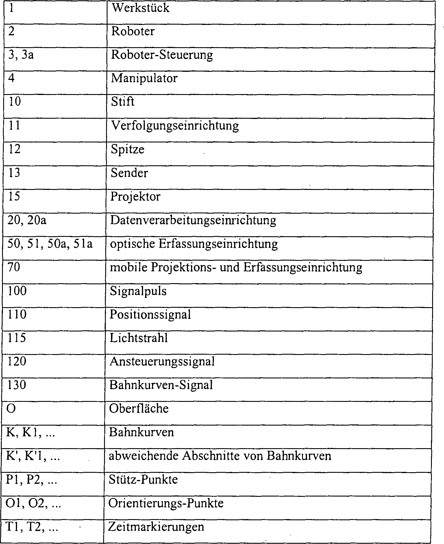
Claims (19)
Priority Applications (4)
| Application Number | Priority Date | Filing Date | Title |
|---|---|---|---|
| DE102005060967A DE102005060967B4 (en) | 2005-12-20 | 2005-12-20 | Method and device for setting up a trajectory of a robot device |
| AT06847035T ATE524771T1 (en) | 2005-12-20 | 2006-12-20 | METHOD AND DEVICE FOR SETTING UP A PATH CURVE OF A ROBOTIC DEVICE |
| PCT/EP2006/070023 WO2007071736A1 (en) | 2005-12-20 | 2006-12-20 | Method and apparatus for establishing a trajectory of a robot device |
| EP06847035A EP1966661B1 (en) | 2005-12-20 | 2006-12-20 | Method and apparatus for establishing a trajectory of a robot device |
Applications Claiming Priority (1)
| Application Number | Priority Date | Filing Date | Title |
|---|---|---|---|
| DE102005060967A DE102005060967B4 (en) | 2005-12-20 | 2005-12-20 | Method and device for setting up a trajectory of a robot device |
Publications (2)
| Publication Number | Publication Date |
|---|---|
| DE102005060967A1 DE102005060967A1 (en) | 2007-06-28 |
| DE102005060967B4 true DE102005060967B4 (en) | 2007-10-25 |
Family
ID=37983579
Family Applications (1)
| Application Number | Title | Priority Date | Filing Date |
|---|---|---|---|
| DE102005060967A Expired - Fee Related DE102005060967B4 (en) | 2005-12-20 | 2005-12-20 | Method and device for setting up a trajectory of a robot device |
Country Status (4)
| Country | Link |
|---|---|
| EP (1) | EP1966661B1 (en) |
| AT (1) | ATE524771T1 (en) |
| DE (1) | DE102005060967B4 (en) |
| WO (1) | WO2007071736A1 (en) |
Cited By (4)
| Publication number | Priority date | Publication date | Assignee | Title |
|---|---|---|---|---|
| DE102008042612A1 (en) * | 2008-10-06 | 2010-04-08 | Kuka Roboter Gmbh | Industrial robots and path planning method for controlling the movement of an industrial robot |
| DE102008062623B4 (en) * | 2008-12-17 | 2016-08-04 | Kuka Roboter Gmbh | Method and device for selecting a stored position of an operating point of a manipulator |
| DE102017005194B3 (en) | 2017-05-31 | 2018-09-13 | Kuka Deutschland Gmbh | Controlling a robot assembly |
| DE202023100841U1 (en) | 2023-02-22 | 2024-05-27 | Kuka Deutschland Gmbh | Robot system |
Families Citing this family (44)
| Publication number | Priority date | Publication date | Assignee | Title |
|---|---|---|---|---|
| DE102006031580A1 (en) | 2006-07-03 | 2008-01-17 | Faro Technologies, Inc., Lake Mary | Method and device for the three-dimensional detection of a spatial area |
| US9551575B2 (en) | 2009-03-25 | 2017-01-24 | Faro Technologies, Inc. | Laser scanner having a multi-color light source and real-time color receiver |
| DE102009015920B4 (en) | 2009-03-25 | 2014-11-20 | Faro Technologies, Inc. | Device for optically scanning and measuring an environment |
| US9113023B2 (en) | 2009-11-20 | 2015-08-18 | Faro Technologies, Inc. | Three-dimensional scanner with spectroscopic energy detector |
| US9210288B2 (en) | 2009-11-20 | 2015-12-08 | Faro Technologies, Inc. | Three-dimensional scanner with dichroic beam splitters to capture a variety of signals |
| DE102009057101A1 (en) | 2009-11-20 | 2011-05-26 | Faro Technologies, Inc., Lake Mary | Device for optically scanning and measuring an environment |
| US9529083B2 (en) | 2009-11-20 | 2016-12-27 | Faro Technologies, Inc. | Three-dimensional scanner with enhanced spectroscopic energy detector |
| US8630314B2 (en) | 2010-01-11 | 2014-01-14 | Faro Technologies, Inc. | Method and apparatus for synchronizing measurements taken by multiple metrology devices |
| US9879976B2 (en) | 2010-01-20 | 2018-01-30 | Faro Technologies, Inc. | Articulated arm coordinate measurement machine that uses a 2D camera to determine 3D coordinates of smoothly continuous edge features |
| US8875409B2 (en) | 2010-01-20 | 2014-11-04 | Faro Technologies, Inc. | Coordinate measurement machines with removable accessories |
| US8898919B2 (en) | 2010-01-20 | 2014-12-02 | Faro Technologies, Inc. | Coordinate measurement machine with distance meter used to establish frame of reference |
| US9607239B2 (en) | 2010-01-20 | 2017-03-28 | Faro Technologies, Inc. | Articulated arm coordinate measurement machine having a 2D camera and method of obtaining 3D representations |
| US8615893B2 (en) | 2010-01-20 | 2013-12-31 | Faro Technologies, Inc. | Portable articulated arm coordinate measuring machine having integrated software controls |
| US9163922B2 (en) | 2010-01-20 | 2015-10-20 | Faro Technologies, Inc. | Coordinate measurement machine with distance meter and camera to determine dimensions within camera images |
| US8683709B2 (en) | 2010-01-20 | 2014-04-01 | Faro Technologies, Inc. | Portable articulated arm coordinate measuring machine with multi-bus arm technology |
| JP5306545B2 (en) | 2010-01-20 | 2013-10-02 | ファロ テクノロジーズ インコーポレーテッド | Coordinate measuring machine with illuminated probe end and method of operation |
| US8677643B2 (en) | 2010-01-20 | 2014-03-25 | Faro Technologies, Inc. | Coordinate measurement machines with removable accessories |
| US20110178754A1 (en) | 2010-01-20 | 2011-07-21 | Faro Technologies, Inc. | Portable Articulated Arm Coordinate Measuring Machine Having Integrated Software Controls |
| US8832954B2 (en) | 2010-01-20 | 2014-09-16 | Faro Technologies, Inc. | Coordinate measurement machines with removable accessories |
| US9628775B2 (en) | 2010-01-20 | 2017-04-18 | Faro Technologies, Inc. | Articulated arm coordinate measurement machine having a 2D camera and method of obtaining 3D representations |
| DE102010019640A1 (en) * | 2010-05-06 | 2011-11-10 | Kuka Roboter Gmbh | Handheld device and method for controlling and / or programming a manipulator |
| DE102010020925B4 (en) | 2010-05-10 | 2014-02-27 | Faro Technologies, Inc. | Method for optically scanning and measuring an environment |
| GB2501390B (en) | 2010-09-08 | 2014-08-06 | Faro Tech Inc | A laser scanner or laser tracker having a projector |
| US9168654B2 (en) | 2010-11-16 | 2015-10-27 | Faro Technologies, Inc. | Coordinate measuring machines with dual layer arm |
| DE102012100609A1 (en) | 2012-01-25 | 2013-07-25 | Faro Technologies, Inc. | Device for optically scanning and measuring an environment |
| DE102012206350A1 (en) * | 2012-04-18 | 2013-10-24 | Deutsches Zentrum für Luft- und Raumfahrt e.V. | Method for operating a robot |
| US8997362B2 (en) | 2012-07-17 | 2015-04-07 | Faro Technologies, Inc. | Portable articulated arm coordinate measuring machine with optical communications bus |
| DE102012015437A1 (en) * | 2012-08-02 | 2014-05-15 | Kuka Roboter Gmbh | Method and programming means for modifying a robot path |
| DE102012109481A1 (en) | 2012-10-05 | 2014-04-10 | Faro Technologies, Inc. | Device for optically scanning and measuring an environment |
| US9513107B2 (en) | 2012-10-05 | 2016-12-06 | Faro Technologies, Inc. | Registration calculation between three-dimensional (3D) scans based on two-dimensional (2D) scan data from a 3D scanner |
| US10067231B2 (en) | 2012-10-05 | 2018-09-04 | Faro Technologies, Inc. | Registration calculation of three-dimensional scanner data performed between scans based on measurements by two-dimensional scanner |
| JP5975010B2 (en) * | 2013-10-17 | 2016-08-23 | 株式会社安川電機 | Teaching system and teaching method |
| DE102015002994A1 (en) * | 2015-03-09 | 2016-09-15 | Kuka Roboter Gmbh | Changing an initially given robot path |
| DE102015122844A1 (en) | 2015-12-27 | 2017-06-29 | Faro Technologies, Inc. | 3D measuring device with battery pack |
| US10754337B2 (en) * | 2016-06-20 | 2020-08-25 | Hypertherm, Inc. | Systems and methods for planning paths to guide robots |
| EP3441035A1 (en) * | 2017-08-10 | 2019-02-13 | Siemens Healthcare GmbH | Visualization system for displaying an area of space and method for operating a visualisation system |
| CN108919750B (en) * | 2018-07-27 | 2020-01-21 | 深圳市雷赛控制技术有限公司 | Non-uniform B-spline-based real-time planning method and device for processing track |
| EP4067079B1 (en) * | 2018-11-13 | 2024-10-23 | Lisa Dräxlmaier GmbH | Method for teaching and/or operating a laminating device |
| CN114096383B (en) | 2019-02-11 | 2024-05-14 | 海别得公司 | Motion allocation in robotic systems |
| DE102019105820A1 (en) | 2019-03-07 | 2020-09-10 | Matheus Service GmbH | Process, system and non-volatile storage medium |
| DE102019107964B3 (en) * | 2019-03-28 | 2020-08-06 | Franka Emika Gmbh | Projection device for a robot manipulator |
| JP7426333B2 (en) * | 2020-11-30 | 2024-02-01 | 株式会社ダイヘン | robot control device |
| CN114131657B (en) * | 2021-12-28 | 2024-01-23 | 芜湖藦卡机器人科技有限公司 | Industrial robot track detection device |
| EP4345560A1 (en) * | 2022-09-29 | 2024-04-03 | Siemens Aktiengesellschaft | Method and device for determining an additive production process of a component and additive production process of the component |
Citations (5)
| Publication number | Priority date | Publication date | Assignee | Title |
|---|---|---|---|---|
| DE4412164A1 (en) * | 1994-04-08 | 1995-10-12 | Micromed Ges Fuer Medizinische | Position indicator for medical tomograph units with dial light indicator |
| DE19618332A1 (en) * | 1995-07-17 | 1997-01-23 | Mitsubishi Electric Corp | Spline interpolation function for numerical control |
| WO2003032129A2 (en) * | 2001-10-11 | 2003-04-17 | Laser Projection Technologies Inc. A Delaware Corporation | Method and system for visualizing surface errors |
| US20050149231A1 (en) * | 2004-01-05 | 2005-07-07 | John Pretlove | Method and a system for programming an industrial robot |
| DE102004020099A1 (en) * | 2004-04-24 | 2005-11-17 | Kuka Roboter Gmbh | Method and device for influencing a multi-axis handling device |
Family Cites Families (2)
| Publication number | Priority date | Publication date | Assignee | Title |
|---|---|---|---|---|
| NO317898B1 (en) * | 2002-05-24 | 2004-12-27 | Abb Research Ltd | Procedure and system for programming an industrial robot |
| EP1510282B1 (en) * | 2003-08-29 | 2008-07-09 | Trumpf Laser- und Systemtechnik GmbH | Device for remote machining workpieces with a laser machining beam |
-
2005
- 2005-12-20 DE DE102005060967A patent/DE102005060967B4/en not_active Expired - Fee Related
-
2006
- 2006-12-20 EP EP06847035A patent/EP1966661B1/en not_active Not-in-force
- 2006-12-20 AT AT06847035T patent/ATE524771T1/en active
- 2006-12-20 WO PCT/EP2006/070023 patent/WO2007071736A1/en not_active Ceased
Patent Citations (5)
| Publication number | Priority date | Publication date | Assignee | Title |
|---|---|---|---|---|
| DE4412164A1 (en) * | 1994-04-08 | 1995-10-12 | Micromed Ges Fuer Medizinische | Position indicator for medical tomograph units with dial light indicator |
| DE19618332A1 (en) * | 1995-07-17 | 1997-01-23 | Mitsubishi Electric Corp | Spline interpolation function for numerical control |
| WO2003032129A2 (en) * | 2001-10-11 | 2003-04-17 | Laser Projection Technologies Inc. A Delaware Corporation | Method and system for visualizing surface errors |
| US20050149231A1 (en) * | 2004-01-05 | 2005-07-07 | John Pretlove | Method and a system for programming an industrial robot |
| DE102004020099A1 (en) * | 2004-04-24 | 2005-11-17 | Kuka Roboter Gmbh | Method and device for influencing a multi-axis handling device |
Non-Patent Citations (4)
| Title |
|---|
| BACZYNSKI,M., BACZYNSKI,J.: "Low cost pointing de- vice for robotic systems", In: Proc. of the 2004 IEEE Int. Conf. on Industrial Technology, 8-10 Dec. 2004, Vol.2, S.955-958 |
| BACZYNSKI,M., BACZYNSKI,J.: "Low cost pointing device for robotic systems", In: Proc. of the 2004 IEEE Int. Conf. on Industrial Technology, 8-10 Dec. 2004, Vol.2, S.955-958 * |
| PAROMTCHIK,I.E., ASAMA,H.: "Laser-Based Guidance of Multiple Mobile Robots", In: Proceedings of the 2001 IEEE/ASME Int. Conf. on Advanced Intelligent Mechatronics, 8-12 July 2001, Vol.1, S.410-415 * |
| SATO,S., SAKANE,S.: "A Human-Robot Interface Using an Interactive Hand Pointer that Projects a Mark in the Real Work Space", In: Proc. of the 2000 IEEE Int. Conf. on Robotics and Automation, 24-28 April 2000, Vol.1, S.589-595 * |
Cited By (6)
| Publication number | Priority date | Publication date | Assignee | Title |
|---|---|---|---|---|
| DE102008042612A1 (en) * | 2008-10-06 | 2010-04-08 | Kuka Roboter Gmbh | Industrial robots and path planning method for controlling the movement of an industrial robot |
| DE102008062623B4 (en) * | 2008-12-17 | 2016-08-04 | Kuka Roboter Gmbh | Method and device for selecting a stored position of an operating point of a manipulator |
| DE102017005194B3 (en) | 2017-05-31 | 2018-09-13 | Kuka Deutschland Gmbh | Controlling a robot assembly |
| DE102017005194C5 (en) | 2017-05-31 | 2022-05-19 | Kuka Deutschland Gmbh | Controlling a robot assembly |
| US11839985B2 (en) | 2017-05-31 | 2023-12-12 | Kuka Deutschland Gmbh | Control of a robot assembly |
| DE202023100841U1 (en) | 2023-02-22 | 2024-05-27 | Kuka Deutschland Gmbh | Robot system |
Also Published As
| Publication number | Publication date |
|---|---|
| DE102005060967A1 (en) | 2007-06-28 |
| EP1966661A1 (en) | 2008-09-10 |
| WO2007071736A1 (en) | 2007-06-28 |
| EP1966661B1 (en) | 2011-09-14 |
| ATE524771T1 (en) | 2011-09-15 |
Similar Documents
| Publication | Publication Date | Title |
|---|---|---|
| DE102005060967B4 (en) | Method and device for setting up a trajectory of a robot device | |
| EP1521211B1 (en) | Method and apparatus for determining the position and orientation of an image receiving device | |
| DE102018112820B4 (en) | Teach position correction device and teach position correction method | |
| DE60127644T2 (en) | Teaching device for a robot | |
| DE602004005776T2 (en) | A method of controlling the welding of a three-dimensional structure with the capture of a two-dimensional image of the structure and with real-time alignments in the third dimension | |
| DE102007033486B4 (en) | Method and system for mixing a virtual data model with an image generated by a camera or a presentation device | |
| DE102018009023B4 (en) | Teaching device for carrying out robot teaching processes and teaching methods | |
| EP1447770B1 (en) | Method and apparatus for visualization of computer-based information | |
| EP2132608B1 (en) | Method and device for controlling robots for welding workpieces | |
| DE102006030130B3 (en) | Workpiece machining method for, e.g., industrial robot, involves compensating deviation of determined actual-position from reference-movement path and deviation of determined actual-speed vector from measured reference-speed vector | |
| EP1424613A1 (en) | method and device for machining a workpiece | |
| DE102019005974A1 (en) | TEACH-IN DEVICE FOR LASER PROCESSING | |
| DE10351669B4 (en) | Method and device for controlling a handling device relative to an object | |
| EP2012208B1 (en) | Programmable hand tool | |
| DE102018125841B4 (en) | Robot, robot system and method for setting a coordinate system of a robot | |
| DE3613096A1 (en) | Method for machining workpieces | |
| EP2091699B1 (en) | Method and device for fine-positioning a tool having a handling device | |
| EP2359202B1 (en) | Method and device for selecting a stored position of a working point of a manipulator | |
| EP3640583A1 (en) | Method for 3d capturing of an object to be measured | |
| DE112022000384T5 (en) | TEACHING APPARATUS AND TEACHING METHOD FOR TEACHING THE OPERATION OF A LASER PROCESSING APPARATUS | |
| EP1915239B1 (en) | Method for generating an environmental image | |
| DE102007043632B4 (en) | Industrial robot with a distance measuring device and method for measuring an object | |
| DE10002230A1 (en) | Adaptive robot guidance method, uses successive measurements with master piece and actual component for determining offset vectors used for adaption of robot movement program | |
| EP3615908A1 (en) | Control device for an inspection apparatus, inspection arrangement having the control device, method for controlling the inspection arrangement, and computer program | |
| DE10048952A1 (en) | Spatial coordinate recording device for workpiece processed by robot has reference unit with reference markings, spaced apart from detector |
Legal Events
| Date | Code | Title | Description |
|---|---|---|---|
| OP8 | Request for examination as to paragraph 44 patent law | ||
| 8364 | No opposition during term of opposition | ||
| R119 | Application deemed withdrawn, or ip right lapsed, due to non-payment of renewal fee |