DE102005049586A1 - Method for generating computerized tomography displays in x-ray computed tomography, comprises scanning an object and reconstructing a first computerized tomography display from an absorption data of an energy spectrum - Google Patents
Method for generating computerized tomography displays in x-ray computed tomography, comprises scanning an object and reconstructing a first computerized tomography display from an absorption data of an energy spectrum Download PDFInfo
- Publication number
- DE102005049586A1 DE102005049586A1 DE102005049586A DE102005049586A DE102005049586A1 DE 102005049586 A1 DE102005049586 A1 DE 102005049586A1 DE 102005049586 A DE102005049586 A DE 102005049586A DE 102005049586 A DE102005049586 A DE 102005049586A DE 102005049586 A1 DE102005049586 A1 DE 102005049586A1
- Authority
- DE
- Germany
- Prior art keywords
- absorption
- different
- materials
- energy spectra
- thicknesses
- Prior art date
- Legal status (The legal status is an assumption and is not a legal conclusion. Google has not performed a legal analysis and makes no representation as to the accuracy of the status listed.)
- Withdrawn
Links
Classifications
-
- A—HUMAN NECESSITIES
- A61—MEDICAL OR VETERINARY SCIENCE; HYGIENE
- A61B—DIAGNOSIS; SURGERY; IDENTIFICATION
- A61B6/00—Apparatus or devices for radiation diagnosis; Apparatus or devices for radiation diagnosis combined with radiation therapy equipment
- A61B6/48—Diagnostic techniques
- A61B6/482—Diagnostic techniques involving multiple energy imaging
-
- A—HUMAN NECESSITIES
- A61—MEDICAL OR VETERINARY SCIENCE; HYGIENE
- A61B—DIAGNOSIS; SURGERY; IDENTIFICATION
- A61B6/00—Apparatus or devices for radiation diagnosis; Apparatus or devices for radiation diagnosis combined with radiation therapy equipment
- A61B6/02—Arrangements for diagnosis sequentially in different planes; Stereoscopic radiation diagnosis
- A61B6/03—Computed tomography [CT]
- A61B6/032—Transmission computed tomography [CT]
-
- G06T12/20—
Landscapes
- Health & Medical Sciences (AREA)
- Life Sciences & Earth Sciences (AREA)
- Engineering & Computer Science (AREA)
- Medical Informatics (AREA)
- Optics & Photonics (AREA)
- Biomedical Technology (AREA)
- Biophysics (AREA)
- High Energy & Nuclear Physics (AREA)
- Veterinary Medicine (AREA)
- Nuclear Medicine, Radiotherapy & Molecular Imaging (AREA)
- Public Health (AREA)
- Pathology (AREA)
- Radiology & Medical Imaging (AREA)
- Physics & Mathematics (AREA)
- Heart & Thoracic Surgery (AREA)
- Molecular Biology (AREA)
- Surgery (AREA)
- Animal Behavior & Ethology (AREA)
- General Health & Medical Sciences (AREA)
- Pulmonology (AREA)
- Theoretical Computer Science (AREA)
- Apparatus For Radiation Diagnosis (AREA)
Abstract
Die Erfindung betrifft ein Verfahren zur kontrastmittelunterstützten Erzeugung von CT-Darstellungen (19) in der Röntgen-Computertomographie, wobei der Blooming-Effekt reduziert wird, indem beim Scan eines Objektes mit zwei unterschiedlichen Energiespektren (S1, S2) das Objekt in drei Materialkomponenten (M1, M2, M3) zerlegt und eine erste Komponente (M1) und deren Materialstärke (dM1) durch Segmentierung bestimmt werden. Anschließend werden die beiden anderen Materialkomponenten (M2, M3) und ihre Materialstärken (dM2, dM3) aufgrund der gemessenen Schwächungswerte (A1, A2) beider Spektren (S1, S2) für jeden Strahl bestimmt und aus den so bekannten Materialstärken (dM1, dM2, dM3) der unterschiedlichen Materialkomponenten (M1, M2, M3) virtuelle Absorptionsdaten (A') mit virtuellen Absorptionskoeffizienten für die einzelnen Materialkomponenten (M1, M2, M3) aufgebaut und zur Rekonstruktion der CT-Darstellung (19) verwendet.The invention relates to a method for contrast-assisted generation of CT images (19) in X-ray computed tomography, wherein the blooming effect is reduced by the object in three material components when scanning an object with two different energy spectra (S 1 , S 2 ) (M 1 , M 2 , M 3 ) decomposed and a first component (M 1 ) and the material thickness (dM 1 ) are determined by segmentation. Subsequently, the two other material components (M 2 , M 3 ) and their material thicknesses (dM 2 , dM 3 ) are determined for each beam on the basis of the measured attenuation values (A 1 , A 2 ) of both spectra (S 1 , S 2 ) so known material thicknesses (dM 1 , dM 2 , dM 3 ) of the different material components (M 1 , M 2 , M 3 ) virtual absorption data (A ') with virtual absorption coefficients for the individual material components (M 1 , M 2 , M 3 ) constructed and used to reconstruct the CT plot (19).
Description
Die Erfindung betrifft ein Verfahren zur CT-Darstellung in der Röntgen-Computertomographie, wobei ein Objekt, welches sich aus N+1 Materialien oder Materialkompositionen mit unterschiedlichen Absorptionskoeffizienten zusammensetzt, durch umlaufende Strahlenfächer, welche eine Vielzahl von Abtaststrahlen im Raum erzeugen, mit N≥2 unterschiedlichen Energiespektren abgetastet wird und CT-Darstellungen von Absorptionskoeffizienten als Schnittbild oder als Volumendaten aus gemessenen Absorptionsdaten rekonstruiert werden.The The invention relates to a method for CT imaging in X-ray computed tomography, being an object made of N + 1 materials or material compositions composed with different absorption coefficients, by circumferential fan beams, which generate a plurality of scanning beams in space, with N≥2 different Energy spectra is scanned and CT representations of absorption coefficients as Section image or as volume data from measured absorption data be reconstructed.
Durch das Vorhandensein mehrerer Materialien in einem durch ein Röntgen-CT-Verfahren gescannten Objekt treten bei der Rekonstruktion und dem daraus entstehenden Bild, insbesondere bei nachfolgenden quantitativen Auswertungen, Artefakte auf, die zu Fehlinterpretationen führen können. Einerseits besteht das Problem einer Strahlaufhärtung, die im Rahmen der Vorverarbeitung von Rohdaten nur pauschal für ein Material, üblicherweise Wasser, korrigiert wird. Da jedoch die Strahlaufhärtungscharakteristiken für unterschiedliche Materialzusammensetzungen und -anordnungen in einem gescannten Objekt, insbesondere in einem Patienten, wie beispielsweise Wasser, Knochen oder Jod, im Falle von Aufnahmen mit Kontrastmitteln, grundlegend verschieden sind, ergeben sich Artefakte in der Rekonstruktion. Andererseits besteht das Problem des sogenannten „Blooming". Bei CT-Angiographien ist es notwendig, Gefäßdurchmesser im Bereich von Stenosen quantitativ auszumessen. Solche Stenosen, die durch kalzifizierte Plaques verursacht werden, erscheinen aufgrund ihres signifikant höheren Absorptionskoeffizienten gegenüber ihrer Umgebung und der bei der Rekonstruktion verwendeten Filter in der Regel größer als ihre tatsächliche Ausdehnung. Dies erschwert die korrekte Ermittlung des Restvolumens der betrachteten Gefäße und führt zu Fehlinterpretationen.By the presence of multiple materials in one by an X-ray CT method Scanned object occur in the reconstruction and the resulting Image, especially in subsequent quantitative evaluations, Artifacts that can lead to misinterpretations. On the one hand, that exists Problem of a beam hardening, the in the context of the preprocessing of raw data only a flat rate for a material, usually Water, is corrected. However, because of the beam hardening characteristics for different Material compositions and arrangements in a scanned object, especially in a patient, such as water, bone or iodine, in the case of photographs with contrast agents, fundamental are different, artefacts result in the reconstruction. On the other hand, there is the problem of so-called "blooming." In CT angiographies it is necessary vessel diameter to measure quantitatively in the area of stenoses. Such stenoses, the caused by calcified plaques appear due to their significantly higher Compared with absorption coefficients their environment and the filters used in the reconstruction usually larger than their actual Expansion. This complicates the correct determination of the residual volume of considered vessels and leads to misinterpretation.
Es ist Aufgabe der Erfindung ein Verfahren zur Erzeugung von CT-Darstellung in der Röntgen-Computertomographie zu finden, welches vornehmlich zu einer Reduktion des Blooming-Effektes führt. Zusätzlich soll auch bei der Rekonstruktion die Strahlaufhärtung, aufgrund der tatsächlichen Gegebenheiten des gescannten Objektes, besser berücksichtigt werden.It The object of the invention is a method for generating a CT image in X-ray computed tomography to find, which leads primarily to a reduction of the blooming effect. In addition, should also in the reconstruction of the beam hardening, due to the actual Conditions of the scanned object, better taken into account become.
Diese Aufgabe wird durch die Merkmale der unabhängigen Patentansprüche gelöst. Vorteilhafte Weiterbildungen der Erfindung sind Gegenstand untergeordneter Ansprüche.These The object is solved by the features of the independent claims. Advantageous developments The invention are subject matter of the subordinate claims.
Die Erfinder haben erkannt, dass es möglich ist, den sogenannten Blooming-Effekt zu reduzieren und gleichzeitig eine verbesserte Strahlaufhärtungskorrektur durchzuführen, indem beim Scan eines Objektes mit zwei unterschiedlichen Energiespektren das Objekt in drei Materialkomponenten zerlegt wird, wobei eine erste Komponente durch Segmentierung bestimmt wird und die beiden anderen Materialkomponenten aufgrund der gemessenen Schwächungswerte beider Spektren für jeden Strahl bestimmt und anschließend aus den so bekannten Materialstärken der unterschiedlichen Materialkomponenten virtuelle Absorptionsdaten mit virtuellen Absorptionskoeffizienten für die einzelnen Materialkomponenten aufgebaut und zu einer Rekonstruktion verwendet werden.The Inventors have recognized that it is possible to use the so-called Reduce blooming effect while improving it beam hardening perform, when scanning an object with two different energy spectra, the Object is decomposed into three material components, with a first Component is determined by segmentation and the other two Material components due to the measured attenuation values of both spectra for each Beam determined and then from the known material thicknesses of different material components virtual absorption data with virtual absorption coefficients for the individual material components built and used for a reconstruction.
Es
wird demgemäß in einem
ersten Schritt aus einem rekonstruierten Bild unter Verwendung eines
einzelnen Spektrums oder einer Kombination der Daten zweier Spektren
durch Segmentierung die räumliche
Verteilung der lokalen Dichte einer Materialkomponente bestimmt.
Dabei kann ein unterer beziehungsweise oberer Schwellwert oder auch
eine Fensterung für
die CT-Werte verwendet werden. Alternativ ist für eine solche Segmentierung
auch eine ρ/z-Zerlegung,
wie es beispielsweise in der Patentanmeldung
Anschließend werden alle Materialdicken unter Verwendung von im Prinzip willkürlichen Schwächungskoeffizienten zu virtuellen pseudo-monochromatischen Schwächungsdaten rückgerechnet. Durch die Wahl eines fiktiven Schwächungskoeffizienten kann der Blooming-Effekt nun signifikant reduziert werden. Grundsätzlich entspricht dies einer Art nichtlinearer Kontrastminderung, die allerdings nicht auf die fertigen Bilddaten, sonder auf die ursprünglich vorliegenden Schwächungsdaten der CT-Messung angewendet wird. Soll im fertigen Bild beispielsweise das ursprünglich segmentierte Material kontrastreich hervorgehoben werden, so kann das ursprünglich segmentierte Bild mit dem Bild aus den virtuellen Schwächungsdaten überlagert werden, so dass entweder eine kontrastreiche Hervorhebung des segmentierten Materials stattfindet oder dieses Material durch eine besondere Farbgebung gekennzeichnet werden kann. Grundsätzlich besteht, falls die betrachteten Materialien oder Materialkomponenten ausreichend signifikante Unterschiede ihrer Schwächungskoeffizienten aufweisen, und auch jedes einzelne Material mit den tatsächlich aufgenommenen Schwächungswerten rekonstruiert und segmentiert wird, die Möglichkeit, dass zusätzlich in einer Mehrfarbendarstellung jedes einzelne Material besonders augenfällig durch Überlagerung mit dem, aus virtuellen Schwächungsdaten rekonstruierten Bild hervorgehoben werden kann.Subsequently, all material thicknesses are recalculated to virtual pseudo-monochromatic attenuation data using, in principle, arbitrary attenuation coefficients. By choosing a fictitious attenuation coefficient, the blooming effect can now be significantly reduced. Basically, this corresponds to a kind of non-linear contrast reduction, which is not applied to the finished image data, but to the original attenuation data of the CT measurement. If, for example, the originally segmented material is to be highlighted in high contrast in the finished image, then the originally segmented image can be overlaid with the image from the virtual attenuation data, so that either a high-contrast emphasis of the segmented material takes place or this material can be characterized by a particular coloration. Basically, if the considered materials or material components sufficiently significant differences in their Schwä In addition, in a multi-color representation, each individual material can be particularly clearly highlighted by superposition with the image reconstructed from the virtual attenuation data.
Entsprechend diesem Grundgedanken schlagen die Erfinder vor, das an sich bekannte Verfahren zur Erzeugung von CT-Darstellungen in der Röntgen-Computertomographie, bei dem ein Objekt, vorzugsweise ein Patient, welches/welcher sich aus N+1 Materialien oder Materialkompositionen mit signifikant unterschiedlichem Absorptionskoeffizienten zusammensetzt, durch umlaufende Strahlenfächer, welche eine Vielzahl von Abtaststrahlen im Raum erzeugen, mit N≥2 unterschiedlichen Energiespektren abgetastet wird und CT-Darstellungen von Absorptionskoeffizienten als Schnittbild oder als Volumendaten aus gemessenen Absorptionsdaten rekonstruiert werden, vor, wobei erfindungsgemäß zumindest die folgenden Verfahrensschritte durchgeführt werden:
- – eine erste CT-Darstellung wird aus den Absorptionsdaten mindestens eines Energiespektrums rekonstruiert und ein erstes Material oder eine erste Materialkomposition durch Kenntnis seines Absorptionskoeffizienten segmentiert,
- – für jeden Abtaststrahl im Raum wird auf der Basis der ersten CT-Darstellung die Materialstärke des ersten Materials oder der ersten Materialkomposition ermittelt,
- – für jeden Abtaststrahl im Raum wird unter Berücksichtigung der bekannten Absorption des ersten Materials aus den N räumlich gleichen Abtaststrahlen unterschiedlicher Energiespektren die Materialstärke der N anderen Materialien oder Materialkompositionen bestimmt,
- – für jeden Abtaststrahl im Raum wird ein virtueller Schwächungswert aus den N+1 bekannten Materialstärken mit neu definierten Absorptionskoeffizienten berechnet,
- – mit den virtuellen Schwächungswerten wird eine zweite CT-Darstellung rekonstruiert.
- A first CT representation is reconstructed from the absorption data of at least one energy spectrum and a first material or a first material composition is segmented by knowledge of its absorption coefficient,
- For each scanning beam in space, the material thickness of the first material or of the first material composition is determined on the basis of the first CT representation,
- For each scanning beam in space, taking into account the known absorption of the first material from the N spatially identical scanning beams of different energy spectra, the material thickness of the N other materials or material compositions is determined,
- For each scanning beam in space, a virtual attenuation value is calculated from the N + 1 known material thicknesses with newly defined absorption coefficients,
- - With the virtual attenuation values, a second CT representation is reconstructed.
Zur Reduktion des Blooming-Effektes ist es vorteilhaft, wenn die Wertespanne der neu definierten Absorptionskoeffizienten kleiner als die Wertespanne der Absorptionskoeffizienten der N+1 Materialien oder Materialkompositionen ist. Es reicht allerdings auch schon zur Verminderung des Blooming-Effektes aus, die neu definierten Absorptionskoeffizienten so zu wählen, dass der Werteabstand untereinander identisch oder möglichst angeglichen ist. Auch dadurch wird der Kontrast an Materialübergängen reduziert, so dass der Blooming-Effekt weiter vermindert wird.to Reduction of the blooming effect, it is advantageous if the range of value the newly defined absorption coefficient is smaller than the value range the absorption coefficient of the N + 1 materials or material compositions is. However, it is enough to reduce the blooming effect out to choose the newly defined absorption coefficient so that the value spacing is identical or as close as possible to one another. Also This reduces the contrast at material transitions, so that the Blooming effect is further reduced.
Grundsätzlich erscheint eine CT-Darstellung, die durch Absorptionskoeffizienten mit kleinerer Wertespanne gebildet wird, weniger kontrastreich, so dass auch einzelne Materialkomponenten schlechter optisch heraus gehoben scheinen. Dieser Nachteil lässt sich beispielsweise dadurch beheben, dass eine dritte CT-Darstellung durch Überlagerung der zweiten CT-Darstellung mit der segmentierten ersten CT-Darstellung erzeugt wird.Basically appears a CT representation by absorption coefficients with smaller Value range is formed, less contrast rich, so that even individual Material components look worse optically lifted out. This disadvantage leaves For example, fix this by having a third CT image by overlay the second CT image is generated with the segmented first CT representation.
In einer besonderen Ausführung des erfindungsgemäßen Verfahrens schlagen die Erfinder weiterhin vor, dass zur Bestimmung der Materialstärken N unterschiedlicher Materialien oder Materialkompositionen auf der Basis einer bekannten Materialstärke des ersten Materials in Abhängigkeit von den Absorptionswerten der N Energiespektren in mindestens einer Lookup-Tabelle zur Verfügung gestellt werden. Hierbei können fehlende Zwischenwerte in der Lookup-Tabelle durch Interpolation ermittelt werden.In a special design the method according to the invention The inventors further propose that for determining the material thicknesses N different Materials or material compositions based on a known material thickness of the first material in dependence from the absorption values of the N energy spectra in at least one Lookup table for disposal be put. Here you can missing intermediate values in the lookup table due to interpolation be determined.
Eine solche Lookup-Tabelle kann beispielsweise folgendermassen ermittelt werden. Für alle Kombinationen der Materialdicken dM1, ..., dMN+1 werden die Absorptionen A1, ..., AN bei den Spektren S1, ..., SN gemessen. Für feste Werte dM1 werden sodann die Abbildungen F_dM1: (dM2, ..., dMN+1) -> (A1, ..., AN) invertiert, was aufgrund der strengen Monotonie in allen Variablen möglich ist. Es ergeben sich Abbildungen G_dM1:(A1, ..., AN) -> :(dM2, ..., dMN+1), mit denen für eine Materialdicke dM1 und den N spektralen Messwerte die übrigen Materialdicken dM2, ..., dMN+1 berechnet werden, und die für feste Werte von dM1 in jeweils N N-dimensionalen Datenfeldern tabelliert werden können. Neben der Messung der Absorptionen können die Abbildungen F_dM1 auch durch eine Berechnung durch eine Computer-Simulation ermittelt werden.Such a look-up table can be determined, for example, as follows. For all combinations of material thicknesses dM 1, ..., dM N + 1, the absorptions A 1, ..., A N are in the spectra S 1, ..., S N measured. For fixed values dM 1 , the diagrams F_dM 1 : (dM 2 , ..., dM N + 1 ) -> (A 1 , ..., A N ) are then inverted, which is possible due to the strict monotonicity in all variables , This gives figures G_dM 1 : (A 1 , ..., A N ) ->: (dM 2 , ..., dM N + 1 ), with which for a material thickness dM 1 and the N spectral measured values the remaining material thicknesses dM 2 , ..., dM N + 1 , and which can be tabulated for fixed values of dM 1 in each of N N-dimensional data fields. In addition to the measurement of the absorptions, the images F_dM 1 can also be determined by a calculation by a computer simulation.
Es ist dabei daraufhin zuweisen, dass durch diese oben beschriebene pseudo-monochromatische Synthetisierung gleichzeitig auch der Effekt einer Strahlaufhärtungskorrektur erreicht wird.It is hereby assign that by these described above pseudo-monochromatic synthesizing at the same time the effect a beam hardening correction is reached.
In einer weiteren Variante des erfindungsgemäßen Verfahrens kann die Bestimmung der Materialstärken N unterschiedlicher Materialien oder Materialkompositionen durch Lösung eines Gleichungssystems mit N nichtlinearen Gleichungen, vorzugsweise Absorptionsgleichungen, und N unbekannten Materialstärken unter Berücksichtigung bekannter Absorptionskoeffizienten der Materialien oder Materialkompositionen in Abhängigkeit von den Energiespektren erfolgen.In a further variant of the method according to the invention, the determination the material thicknesses N different materials or material compositions solution a system of equations with N nonlinear equations, preferably Absorption equations, and N unknown material thicknesses below consideration known absorption coefficient of the materials or material compositions dependent on done by the energy spectra.
Die Erfinder schlagen weiterhin vor, dass die Segmentierung des ersten Materials oder der ersten Materialkomposition durch Setzen mindestens eines Grenzwertes für den Absorptionskoeffizienten erfolgt. Es kann sich dabei entweder um einen Schwellwert handeln, so dass alle Bildwerte mit einem Absorptionskoeffizienten über diesem Grenzwert als materialspezifisch angesehen werden, oder es besteht die Möglichkeit, einen oberen und unteren Grenzwert zu bilden, als ein Fenster zu setzen oder einen unteren Grenzwert zu definieren, so dass alle Bildwerte unterhalb dieses Grenzwertes als materialspezifisch für die Segmentierung angesehen werden.The inventors also propose that the segmentation of the first material or of the first material composition be effected by setting at least one limit value for the absorption coefficient. It can either be a threshold, so that all image values with an Ab Sorption coefficients above this threshold are considered material specific, or it is possible to form an upper and lower limit than to set a window or define a lower limit such that all image values below that threshold are considered material specific for the segmentation.
Betrachtet man das wesentliche Anwendungsgebiet des erfindungsgemäßen Verfahrens, nämlich die CT-Angiographie, in der ein Patient gescannt wird, wobei der Patient bezüglich der Absorptionskoeffizienten im Wesentlichen aus wasserähnlichem Gewebe, kalziumhaltigen Knochen beziehungsweise Plaques und, vorzugsweise jodhaltigem Kontrastmittel besteht, so kann als erste Materialkomposition im Wesentlichen Kalzium, als zweite Materialkomposition im Wesentlichen Jod und als dritte Materialkomposition im Wesentlichen Wasser angesehen werden.considered one the essential application of the method according to the invention, namely the CT angiography, in which a patient is scanned, with the patient in terms of the absorption coefficient is substantially water-like Tissue, calcium-containing bone or plaques and, preferably iodine-containing contrast agent, so may be the first material composition essentially calcium, as a second material composition essentially Iodine and as a third material composition essentially considered water become.
Bei der CT-Darstellung wird außerdem vorgeschlagen, dass zumindest einem Material oder einer Materialkomposition eine bestimmte Farbe zugeordnet wird, wobei hier zur Verbesserung des Kontrastes für jede einzelne Materialkomposition eine Segmentierung aus den originären CT-Daten durchgeführt werden kann, so dass anschließend eine entsprechende Bildüberlagerung mit den segmentierten CT-Daten vorgenommen werden kann.at the CT representation will also work proposed that at least one material or material composition assigned to a particular color, here for improvement of contrast for every single material composition a segmentation from the original CT data carried out can be, so that afterwards a corresponding image overlay can be made with the segmented CT data.
Grundsätzlich eignet sich das vorgeschlagene Verfahren für jegliche Art von CT-Geräten, wobei die unterschiedlichen verwendeten Energiespektren beispielsweise durch eine Veränderung der Beschleunigungsspannung in der Röntgenstrahlung erzeugenden Röhre erreicht werden. Es besteht auch die Möglichkeit, durch entsprechende Zwischenfilter die Röntgenstrahlung unterschiedlich aufzuhärten, so dass für den Scan unterschiedliche Röntgenspektren zur Verfügung stehen. Für diese Varianten besteht die Möglichkeit, ein CT-Gerät mit einem einzigen Fokus/Detektor-System zu verwenden. Alternativ kann auch ein CT-Gerät mit mehreren Fokus/Detektor-Systemen genutzt werden, wobei bevorzugt jedes Fokus/Detektor-System zum Scan ein anderes Energiespektrum verwendet wird. Wird beispielsweise ein doppeltes Fokus/Detektor-System mit unterschiedlichen Beschleunigungsspannungen genutzt, so ist es möglich durch unterschiedliche Filterung insgesamt wenigstens vier verschiedene Spektren zum Scan zu verwenden, wobei das gescannte Objekt insgesamt in fünf Materialkompositionen zerlegt werden kann.Basically suitable the proposed method for any type of CT equipment, the different energy spectra used for example by a change the acceleration voltage in the X-ray generating Tube reached become. There is also the possibility by corresponding intermediate filter, the X-radiation differently to harden, so that for the scan different X-ray spectra to disposal stand. For these variants it is possible a CT device to use with a single focus / detector system. alternative can also be a CT device with multiple focus / detector systems, preferably each Focus / detector system used to scan another energy spectrum becomes. For example, if a double focus / detector system with used different acceleration voltages, so it is possible by different filtering altogether at least four different To use spectra to scan with the scanned object in total in five Material compositions can be decomposed.
Es wird daraufhin gewiesen, dass es auch im Rahmen der Erfindung liegt, bei ausreichend unterschiedlichen Absorptionskoeffizienten der Materialien durch die primäre Segmentierung diese unterschiedlichen Materialien für sich zu segmentieren und auf der Basis der Kenntnis der Lage und Mischung dieser Materialien im gescannten Objekt mit einem Scan mit N unterschiedlichen Energiespektren auch N+J Materialien zu bestimmen, wobei J der Anzahl der Materialien entspricht, die in der primären Zerlegung segmentierbar sind.It is pointed out that it is also within the scope of the invention with sufficiently different absorption coefficients of the materials through the primary Segmentation these different materials for themselves segment and based on the knowledge of the situation and mix of these materials in the scanned object with a scan of N different Energy spectra also determine N + J materials, where J is the number corresponds to the materials that can be segmented in the primary decomposition are.
Im
Folgenden wird die Erfindung anhand eines bevorzugten Ausführungsbeispieles
mit Hilfe der Figuren näher
beschrieben, wobei nur die zum Verständnis der Erfindung notwendigen
Merkmale dargestellt sind. Gleiche Elemente sind in den verschiedenen
Figuren mit den gleichen Bezugszeichen versehen, wobei diese die
folgende Bedeutung haben:
Es zeigen im Einzelnen:It show in detail:
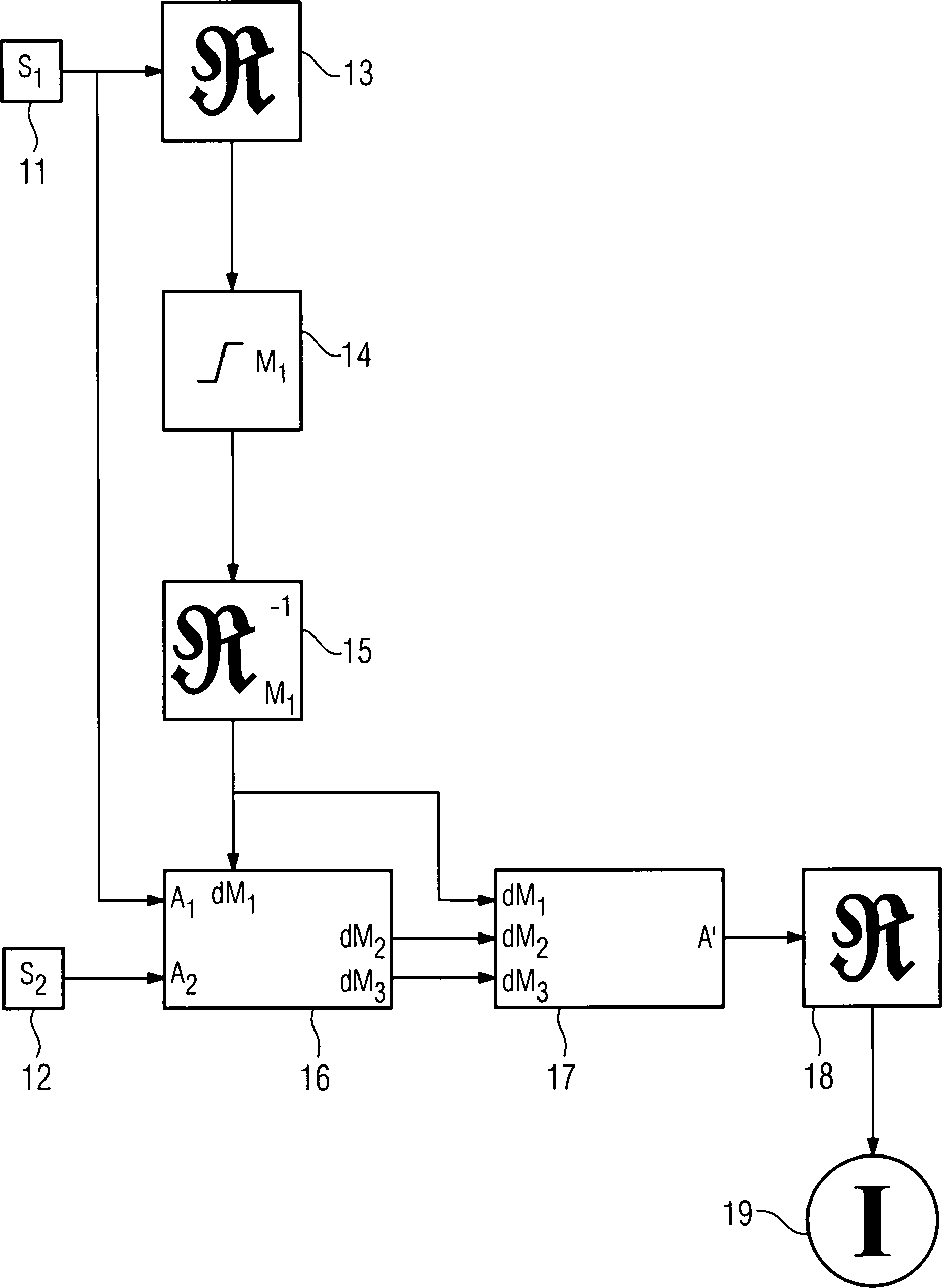
Die
Die
Auf
der Basis der segmentierten Daten wird nun im Schritt
Es
entsteht also eine CT-Darstellung
Da
eine derartige Darstellung mit verminderter Spreizung der Absorptionskoeffizienten
verminderten Kontrast aufweist, schlagen die Erfinder weiterhin
vor, dass zusätzlich
die in der Segmentierung gewonnenen Daten mit dem rekonstruierten
Bild überlagert
werden, damit bezüglich
des ausgewählten
Materials oder der Materialkomponente M1 eine leichter
interpretierbare Darstellung entsteht. Ein solches Verfahren ist
beispielhaft in der
Die
In
der
Die
Es versteht sich, dass die vorstehend genannten Merkmale der Erfindung nicht nur in der jeweils angegebenen Kombination, sondern auch in anderen Kombinationen oder in Alleinstellung verwendbar sind, ohne den Rahmen der Erfindung zu verlassen.It it is understood that the above features of the invention not only in the specified combination, but also in others Combinations or alone, without the frame to leave the invention.
Insgesamt wird also durch diese Erfindung ein Verfahren zur kontrastmittelunterstützten Erzeugung von CT-Darstellungen in der Röntgen-Computertomographie vorgestellt, wobei der Blooming-Effekt reduziert wird, indem beim Scan eines Objektes mit zwei unterschiedlichen Energiespektren S1 und S2 das Objekt in drei Materialkomponenten M1, M2 und M3 zerlegt und eine erste Komponente M1 und deren Materialstärke dM1 durch Segmentierung bestimmt wird. Anschließend werden die beiden anderen Materialkomponenten M2 und M3 und ihrer Materialstärken dM2 und dM3 aufgrund der gemessenen Schwächungswerte A1 und A2 beider Spektren S1 und S2 für jeden Strahl bestimmt und aus den so bekannten Materialstärken dM1, dM2 und dM3 der unterschiedlichen Materialkomponenten M1, M2 und M3 virtuelle Absorptionsdaten A' mit virtuellen Absorptionskoeffizienten für die einzelnen Materialkomponenten M1, M2 und M3 aufgebaut und zur Rekonstruktion der zu fertigen CT-Darstellung verwendet.Overall, therefore, a method for the contrast-assisted generation of CT images in X-ray computed tomography is presented by the invention, wherein the blooming effect is reduced by the object in three material components M when scanning an object with two different energy spectra S 1 and S 2 1 , M 2 and M 3 decomposed and a first component M 1 and the material thickness dM 1 is determined by segmentation. Subsequently, the two other material components M 2 and M 3 and their material thicknesses dM 2 and dM 3 are determined on the basis of the measured attenuation values A 1 and A 2 of both spectra S 1 and S 2 for each beam and from the material thicknesses dM 1 , dM 2 known in this way and dM 3 of the different material components M 1 , M 2 and M 3 built virtual absorption data A 'with virtual absorption coefficients for the individual material components M 1 , M 2 and M 3 and used to reconstruct the ready-to-CT image.
Claims (16)
Priority Applications (4)
| Application Number | Priority Date | Filing Date | Title |
|---|---|---|---|
| DE102005049586A DE102005049586A1 (en) | 2005-10-17 | 2005-10-17 | Method for generating computerized tomography displays in x-ray computed tomography, comprises scanning an object and reconstructing a first computerized tomography display from an absorption data of an energy spectrum |
| US11/581,148 US20070092056A1 (en) | 2005-10-17 | 2006-10-16 | Method for generating CT displays in x ray computed tomography |
| JP2006281221A JP2007111525A (en) | 2005-10-17 | 2006-10-16 | Computerized tomographic image creation method in X-ray computed tomography |
| CNA2006101309573A CN101023875A (en) | 2005-10-17 | 2006-10-17 | Computer tomographic image creating method in X-ray computer tomography |
Applications Claiming Priority (1)
| Application Number | Priority Date | Filing Date | Title |
|---|---|---|---|
| DE102005049586A DE102005049586A1 (en) | 2005-10-17 | 2005-10-17 | Method for generating computerized tomography displays in x-ray computed tomography, comprises scanning an object and reconstructing a first computerized tomography display from an absorption data of an energy spectrum |
Publications (1)
| Publication Number | Publication Date |
|---|---|
| DE102005049586A1 true DE102005049586A1 (en) | 2007-04-26 |
Family
ID=37905126
Family Applications (1)
| Application Number | Title | Priority Date | Filing Date |
|---|---|---|---|
| DE102005049586A Withdrawn DE102005049586A1 (en) | 2005-10-17 | 2005-10-17 | Method for generating computerized tomography displays in x-ray computed tomography, comprises scanning an object and reconstructing a first computerized tomography display from an absorption data of an energy spectrum |
Country Status (4)
| Country | Link |
|---|---|
| US (1) | US20070092056A1 (en) |
| JP (1) | JP2007111525A (en) |
| CN (1) | CN101023875A (en) |
| DE (1) | DE102005049586A1 (en) |
Cited By (6)
| Publication number | Priority date | Publication date | Assignee | Title |
|---|---|---|---|---|
| WO2009130491A1 (en) * | 2008-04-24 | 2009-10-29 | Durham Scientific Crystals Limited | Method and apparatus for inspection of materials |
| DE102008045633A1 (en) | 2008-09-03 | 2010-03-04 | Siemens Aktiengesellschaft | Computer tomography (CT) method for improved display of multi-energy CT exposures/photographs applies contrast media along a system axis |
| DE102008045449A1 (en) | 2008-09-02 | 2010-03-04 | Siemens Aktiengesellschaft | Method of making computed tomographic images of a patient with metallic parts |
| DE102011083727A1 (en) | 2011-09-29 | 2013-04-04 | Siemens Aktiengesellschaft | Method for generating a noise-reduced CT image data set, computing system and CT system |
| US8699662B2 (en) | 2008-04-24 | 2014-04-15 | Kromek Limited | Determination of composition of liquids |
| EP2997900A4 (en) * | 2013-05-15 | 2017-01-04 | Kyoto University | X-ray ct image processing method, x-ray ct image processing program, and x-ray ct image device |
Families Citing this family (29)
| Publication number | Priority date | Publication date | Assignee | Title |
|---|---|---|---|---|
| BRPI0610951A2 (en) * | 2005-06-02 | 2010-08-03 | Cargill Inc | genetically modified yeast of issatchenkia orientalis and closely related species and fermentation processes using them |
| DE102007024409A1 (en) * | 2007-05-25 | 2008-11-27 | Siemens Ag | Process and X-ray CT system for generating computer tomographic images |
| WO2009012200A2 (en) * | 2007-07-13 | 2009-01-22 | Mayo Foundation For Medical Education And Research | Object identification in dual energy contrast-enhanced ct images |
| JP5213016B2 (en) * | 2007-09-27 | 2013-06-19 | ジーイー・メディカル・システムズ・グローバル・テクノロジー・カンパニー・エルエルシー | X-ray CT system |
| DE102007046359B4 (en) * | 2007-09-27 | 2016-02-04 | Siemens Aktiengesellschaft | Method and device for creating material-selective volume images |
| JP5220374B2 (en) * | 2007-09-27 | 2013-06-26 | ジーイー・メディカル・システムズ・グローバル・テクノロジー・カンパニー・エルエルシー | X-ray CT system |
| JP5501559B2 (en) * | 2007-10-26 | 2014-05-21 | ジーイー・メディカル・システムズ・グローバル・テクノロジー・カンパニー・エルエルシー | X-ray CT apparatus and image correction method |
| JP5329103B2 (en) * | 2008-02-01 | 2013-10-30 | ジーイー・メディカル・システムズ・グローバル・テクノロジー・カンパニー・エルエルシー | Image processing apparatus and X-ray CT apparatus |
| US8194961B2 (en) * | 2008-04-21 | 2012-06-05 | Kabushiki Kaisha Toshiba | Method, apparatus, and computer-readable medium for pre-reconstruction decomposition and calibration in dual energy computed tomography |
| JP5337416B2 (en) * | 2008-07-02 | 2013-11-06 | 株式会社東芝 | Image processing apparatus and diagnostic imaging apparatus |
| JP5588994B2 (en) * | 2008-11-25 | 2014-09-10 | コーニンクレッカ フィリップス エヌ ヴェ | Spectral imaging |
| US8115784B2 (en) * | 2008-11-26 | 2012-02-14 | General Electric Company | Systems and methods for displaying multi-energy data |
| US8260023B2 (en) * | 2008-11-26 | 2012-09-04 | General Electric Company | Forward projection for the generation of computed tomography images at arbitrary spectra |
| US7983382B2 (en) * | 2008-11-26 | 2011-07-19 | General Electric Company | System and method for material segmentation utilizing computed tomography scans |
| US9036879B2 (en) * | 2008-11-28 | 2015-05-19 | General Electric Company | Multi-material decomposition using dual energy computed tomography |
| KR101689866B1 (en) * | 2010-07-29 | 2016-12-27 | 삼성전자주식회사 | Method and apparatus of processing image and medical image system employing the same |
| US10186056B2 (en) * | 2011-03-21 | 2019-01-22 | General Electric Company | System and method for estimating vascular flow using CT imaging |
| US9888902B2 (en) * | 2011-07-12 | 2018-02-13 | Hitachi, Ltd. | X-ray CT device, calcuration device, recording medium for X-ray CT device, and maintenance method for X-ray CT device |
| JP5965799B2 (en) * | 2012-09-20 | 2016-08-10 | 株式会社日立製作所 | X-ray tomography method and X-ray tomography apparatus |
| CN104700389B (en) | 2013-12-09 | 2019-08-13 | 通用电气公司 | Object identifying method in dual intensity CT scan image |
| US9964499B2 (en) * | 2014-11-04 | 2018-05-08 | Toshiba Medical Systems Corporation | Method of, and apparatus for, material classification in multi-energy image data |
| US9697603B2 (en) * | 2014-12-19 | 2017-07-04 | Toshiba Medical Systems Corporation | Medical image data processing system and method for vessel segmentation using pre- and post-contrast data |
| CN104605880B (en) * | 2014-12-30 | 2017-06-16 | 沈阳东软医疗系统有限公司 | The generation method and device of a kind of hardening effect data |
| RU2649048C1 (en) | 2016-11-25 | 2018-03-29 | Самсунг Электроникс Ко., Лтд. | Compact spectrometer system intended for non-invasive measurement of spectra of absorption and transmission of specimens of biological material |
| JP6667462B2 (en) * | 2017-02-21 | 2020-03-18 | 富士フイルム株式会社 | Energy subtraction processing apparatus, method and program |
| US11158095B2 (en) * | 2018-08-24 | 2021-10-26 | General Electric Company | System and method for reducing artifact bloom in a reconstructed object |
| JP7467253B2 (en) * | 2019-07-08 | 2024-04-15 | キヤノンメディカルシステムズ株式会社 | X-ray CT system and medical processing equipment |
| CN112697821B (en) * | 2020-12-02 | 2022-12-02 | 赛诺威盛科技(北京)股份有限公司 | Multi-energy spectrum CT scanning method and device, electronic equipment and CT equipment |
| CN113100803B (en) * | 2021-04-20 | 2024-07-19 | 西门子数字医疗科技(上海)有限公司 | Method, apparatus, computer device and medium for displaying venous thrombosis |
Citations (3)
| Publication number | Priority date | Publication date | Assignee | Title |
|---|---|---|---|---|
| DE10143131A1 (en) * | 2001-09-03 | 2003-04-03 | Siemens Ag | Procedure for the determination of density and atomic number distributions in radiographic examination procedures |
| US20040184574A1 (en) * | 2002-07-23 | 2004-09-23 | Xiaoye Wu | Method and apparatus for generating a density map using dual-energy CT |
| US20050084069A1 (en) * | 2003-10-16 | 2005-04-21 | Yanfeng Du | Methods and apparatus for identification and imaging of specific materials |
Family Cites Families (11)
| Publication number | Priority date | Publication date | Assignee | Title |
|---|---|---|---|---|
| US4686695A (en) * | 1979-02-05 | 1987-08-11 | Board Of Trustees Of The Leland Stanford Junior University | Scanned x-ray selective imaging system |
| US5319547A (en) * | 1990-08-10 | 1994-06-07 | Vivid Technologies, Inc. | Device and method for inspection of baggage and other objects |
| US5727041A (en) * | 1996-11-13 | 1998-03-10 | General Electric Company | Methods and apparatus for reducing partial volume image artifacts |
| US5953444A (en) * | 1997-10-22 | 1999-09-14 | University Of Pennsylvania | Method for improved correction of spectrum hardening artifacts in computed tomography images |
| US6226352B1 (en) * | 1998-09-08 | 2001-05-01 | Veritas Pharmaceuticals, Inc. | System and method for radiographic imaging of tissue |
| US6324240B1 (en) * | 1998-11-12 | 2001-11-27 | The Board Of Trustees Of The Leland Stanford Junior University | Method for beam hardening correction in quantitative computed X-ray tomography |
| DE19943183A1 (en) * | 1999-09-09 | 2001-03-15 | Heimann Systems Gmbh & Co | Method for color matching an image, in particular an X-ray image |
| US6507633B1 (en) * | 2001-02-15 | 2003-01-14 | The Regents Of The University Of Michigan | Method for statistically reconstructing a polyenergetic X-ray computed tomography image and image reconstructor apparatus utilizing the method |
| DE10160613A1 (en) * | 2001-12-11 | 2003-06-26 | Siemens Ag | X-ray apparatus for determining the distribution of density and atomic number in an examination object is based on a conventional CT device with an additional two-part filter placed between the source and object |
| US6898263B2 (en) * | 2002-11-27 | 2005-05-24 | Ge Medical Systems Global Technology Company, Llc | Method and apparatus for soft-tissue volume visualization |
| US7272429B2 (en) * | 2002-11-27 | 2007-09-18 | Ge Medical Systems Global Technology Company, Llc | Methods and apparatus for facilitating a reduction in artifacts |
-
2005
- 2005-10-17 DE DE102005049586A patent/DE102005049586A1/en not_active Withdrawn
-
2006
- 2006-10-16 US US11/581,148 patent/US20070092056A1/en not_active Abandoned
- 2006-10-16 JP JP2006281221A patent/JP2007111525A/en not_active Withdrawn
- 2006-10-17 CN CNA2006101309573A patent/CN101023875A/en active Pending
Patent Citations (3)
| Publication number | Priority date | Publication date | Assignee | Title |
|---|---|---|---|---|
| DE10143131A1 (en) * | 2001-09-03 | 2003-04-03 | Siemens Ag | Procedure for the determination of density and atomic number distributions in radiographic examination procedures |
| US20040184574A1 (en) * | 2002-07-23 | 2004-09-23 | Xiaoye Wu | Method and apparatus for generating a density map using dual-energy CT |
| US20050084069A1 (en) * | 2003-10-16 | 2005-04-21 | Yanfeng Du | Methods and apparatus for identification and imaging of specific materials |
Cited By (11)
| Publication number | Priority date | Publication date | Assignee | Title |
|---|---|---|---|---|
| WO2009130491A1 (en) * | 2008-04-24 | 2009-10-29 | Durham Scientific Crystals Limited | Method and apparatus for inspection of materials |
| US8537968B2 (en) | 2008-04-24 | 2013-09-17 | Kromek Limited | Method and apparatus for inspection of materials |
| US8699662B2 (en) | 2008-04-24 | 2014-04-15 | Kromek Limited | Determination of composition of liquids |
| DE102008045449A1 (en) | 2008-09-02 | 2010-03-04 | Siemens Aktiengesellschaft | Method of making computed tomographic images of a patient with metallic parts |
| DE102008045449B4 (en) * | 2008-09-02 | 2016-03-31 | Siemens Aktiengesellschaft | Method for producing computed tomographic images of a patient with metallic components and computer system for carrying out the method |
| DE102008045633A1 (en) | 2008-09-03 | 2010-03-04 | Siemens Aktiengesellschaft | Computer tomography (CT) method for improved display of multi-energy CT exposures/photographs applies contrast media along a system axis |
| DE102008045633B4 (en) * | 2008-09-03 | 2011-08-25 | Siemens Aktiengesellschaft, 80333 | Method for improved display of multi-energy CT images and associated computer system |
| DE102011083727A1 (en) | 2011-09-29 | 2013-04-04 | Siemens Aktiengesellschaft | Method for generating a noise-reduced CT image data set, computing system and CT system |
| US9186114B2 (en) | 2011-09-29 | 2015-11-17 | Siemens Aktiengesellschaft | Method for producing a noise-reduced CT image data record, computer system, and CT system |
| DE102011083727B4 (en) | 2011-09-29 | 2021-12-30 | Siemens Healthcare Gmbh | Method for generating a noise-reduced CT image data set, computing system and CT system |
| EP2997900A4 (en) * | 2013-05-15 | 2017-01-04 | Kyoto University | X-ray ct image processing method, x-ray ct image processing program, and x-ray ct image device |
Also Published As
| Publication number | Publication date |
|---|---|
| US20070092056A1 (en) | 2007-04-26 |
| JP2007111525A (en) | 2007-05-10 |
| CN101023875A (en) | 2007-08-29 |
Similar Documents
| Publication | Publication Date | Title |
|---|---|---|
| DE102005049586A1 (en) | Method for generating computerized tomography displays in x-ray computed tomography, comprises scanning an object and reconstructing a first computerized tomography display from an absorption data of an energy spectrum | |
| DE2916486C2 (en) | ||
| EP2150179B1 (en) | Selection method for two contrast media for use in a dual-energy ct examination, contrast media combination and generation of ct images using a contrast media combination and different energy spectra | |
| DE102011004120B4 (en) | Method, image data record processing device, X-ray system and computer program for the correction of image data of an examination object | |
| DE102016203257B4 (en) | Generating contrast-enhanced image data based on multi-energy X-ray imaging | |
| DE102011076346B4 (en) | Method and computer tomography system for generating tomographic image data sets | |
| DE102009037243A1 (en) | Method for highlighting objects in interventional angiographic examinations | |
| DE10356116A1 (en) | Method and apparatus for facilitating artifact reduction | |
| WO2007087789A1 (en) | Method for producing projective and tomographic images using an x-ray system | |
| DE2733586A1 (en) | DEVICE FOR THE PRODUCTION OF ENERGY-DEPENDENT ROENTINE IMAGES OF AN OBJECT | |
| DE102004042491A1 (en) | A method for generating tomographic slice images of an examination subject with at least two angularly offset beams and computed tomography device for performing this method | |
| DE102004060580A1 (en) | A method for generating a computed tomographic representation of tissue structures using a contrast agent application | |
| DE102007014829B3 (en) | Method for scattered radiation correction in imaging X-ray devices and X-ray imaging system | |
| EP1764040A2 (en) | Method for radiologic 3D imaging with reduced artefacts, medical imaging device and method of establishing a treatment plan | |
| DE102013206415A1 (en) | Automatic extraction of optimized output data | |
| DE102011083727B4 (en) | Method for generating a noise-reduced CT image data set, computing system and CT system | |
| DE102021201809A1 (en) | Generation of X-ray image data based on a location-dependent varying weighting of base materials | |
| EP3797698A1 (en) | Method for generating a synthetic mammogram based on dual-energy tomosynthesis capture | |
| DE102007040519B4 (en) | Method for reducing image noise in the context of taking an image with two different X-ray spectra | |
| DE10352013A1 (en) | Method and device for the spatially resolved determination of element concentrations in examination objects | |
| DE102008045633B4 (en) | Method for improved display of multi-energy CT images and associated computer system | |
| DE102009057716A1 (en) | Method for reconstructing computer tomographic image data of patient, involves straightening projections under utilization of variable and/or weighting complementary projections under utilization of variable | |
| DE102008037348B4 (en) | Method and X-ray CT system for generating tomographic representations from projection data relating to three different energy ranges | |
| DE102012208507A1 (en) | Method for determining beam hardening corrected sinogram values in X-ray computed tomography examination, involves recording logarithmized sinogram data for radiation by wedge filter or phantom, and calculating theoretical sinogram data | |
| DE102006002037A1 (en) | Method for processing diagnostic image data |
Legal Events
| Date | Code | Title | Description |
|---|---|---|---|
| OP8 | Request for examination as to paragraph 44 patent law | ||
| 8139 | Disposal/non-payment of the annual fee |