DE102005045393B4 - Method for dosing solutions - Google Patents
Method for dosing solutions Download PDFInfo
- Publication number
- DE102005045393B4 DE102005045393B4 DE102005045393.7A DE102005045393A DE102005045393B4 DE 102005045393 B4 DE102005045393 B4 DE 102005045393B4 DE 102005045393 A DE102005045393 A DE 102005045393A DE 102005045393 B4 DE102005045393 B4 DE 102005045393B4
- Authority
- DE
- Germany
- Prior art keywords
- fluid
- volumes
- pump
- dosing
- solution
- Prior art date
- Legal status (The legal status is an assumption and is not a legal conclusion. Google has not performed a legal analysis and makes no representation as to the accuracy of the status listed.)
- Expired - Fee Related
Links
Images


Classifications
-
- A—HUMAN NECESSITIES
- A61—MEDICAL OR VETERINARY SCIENCE; HYGIENE
- A61M—DEVICES FOR INTRODUCING MEDIA INTO, OR ONTO, THE BODY; DEVICES FOR TRANSDUCING BODY MEDIA OR FOR TAKING MEDIA FROM THE BODY; DEVICES FOR PRODUCING OR ENDING SLEEP OR STUPOR
- A61M5/00—Devices for bringing media into the body in a subcutaneous, intra-vascular or intramuscular way; Accessories therefor, e.g. filling or cleaning devices, arm-rests
- A61M5/14—Infusion devices, e.g. infusing by gravity; Blood infusion; Accessories therefor
- A61M5/168—Means for controlling media flow to the body or for metering media to the body, e.g. drip meters, counters ; Monitoring media flow to the body
- A61M5/16804—Flow controllers
- A61M5/16827—Flow controllers controlling delivery of multiple fluids, e.g. sequencing, mixing or via separate flow-paths
-
- A—HUMAN NECESSITIES
- A61—MEDICAL OR VETERINARY SCIENCE; HYGIENE
- A61M—DEVICES FOR INTRODUCING MEDIA INTO, OR ONTO, THE BODY; DEVICES FOR TRANSDUCING BODY MEDIA OR FOR TAKING MEDIA FROM THE BODY; DEVICES FOR PRODUCING OR ENDING SLEEP OR STUPOR
- A61M5/00—Devices for bringing media into the body in a subcutaneous, intra-vascular or intramuscular way; Accessories therefor, e.g. filling or cleaning devices, arm-rests
- A61M5/14—Infusion devices, e.g. infusing by gravity; Blood infusion; Accessories therefor
- A61M5/168—Means for controlling media flow to the body or for metering media to the body, e.g. drip meters, counters ; Monitoring media flow to the body
- A61M5/16831—Monitoring, detecting, signalling or eliminating infusion flow anomalies
-
- A—HUMAN NECESSITIES
- A61—MEDICAL OR VETERINARY SCIENCE; HYGIENE
- A61M—DEVICES FOR INTRODUCING MEDIA INTO, OR ONTO, THE BODY; DEVICES FOR TRANSDUCING BODY MEDIA OR FOR TAKING MEDIA FROM THE BODY; DEVICES FOR PRODUCING OR ENDING SLEEP OR STUPOR
- A61M2205/00—General characteristics of the apparatus
- A61M2205/02—General characteristics of the apparatus characterised by a particular materials
- A61M2205/0244—Micromachined materials, e.g. made from silicon wafers, microelectromechanical systems [MEMS] or comprising nanotechnology
-
- A—HUMAN NECESSITIES
- A61—MEDICAL OR VETERINARY SCIENCE; HYGIENE
- A61M—DEVICES FOR INTRODUCING MEDIA INTO, OR ONTO, THE BODY; DEVICES FOR TRANSDUCING BODY MEDIA OR FOR TAKING MEDIA FROM THE BODY; DEVICES FOR PRODUCING OR ENDING SLEEP OR STUPOR
- A61M2205/00—General characteristics of the apparatus
- A61M2205/02—General characteristics of the apparatus characterised by a particular materials
- A61M2205/0272—Electro-active or magneto-active materials
- A61M2205/0294—Piezoelectric materials
-
- A—HUMAN NECESSITIES
- A61—MEDICAL OR VETERINARY SCIENCE; HYGIENE
- A61M—DEVICES FOR INTRODUCING MEDIA INTO, OR ONTO, THE BODY; DEVICES FOR TRANSDUCING BODY MEDIA OR FOR TAKING MEDIA FROM THE BODY; DEVICES FOR PRODUCING OR ENDING SLEEP OR STUPOR
- A61M2205/00—General characteristics of the apparatus
- A61M2205/33—Controlling, regulating or measuring
- A61M2205/3331—Pressure; Flow
- A61M2205/3351—Controlling upstream pump pressure
-
- A—HUMAN NECESSITIES
- A61—MEDICAL OR VETERINARY SCIENCE; HYGIENE
- A61M—DEVICES FOR INTRODUCING MEDIA INTO, OR ONTO, THE BODY; DEVICES FOR TRANSDUCING BODY MEDIA OR FOR TAKING MEDIA FROM THE BODY; DEVICES FOR PRODUCING OR ENDING SLEEP OR STUPOR
- A61M5/00—Devices for bringing media into the body in a subcutaneous, intra-vascular or intramuscular way; Accessories therefor, e.g. filling or cleaning devices, arm-rests
- A61M5/14—Infusion devices, e.g. infusing by gravity; Blood infusion; Accessories therefor
- A61M5/168—Means for controlling media flow to the body or for metering media to the body, e.g. drip meters, counters ; Monitoring media flow to the body
- A61M5/16804—Flow controllers
- A61M5/16809—Flow controllers by repeated filling and emptying of an intermediate volume
Landscapes
- Health & Medical Sciences (AREA)
- Vascular Medicine (AREA)
- Engineering & Computer Science (AREA)
- Anesthesiology (AREA)
- Biomedical Technology (AREA)
- Heart & Thoracic Surgery (AREA)
- Hematology (AREA)
- Life Sciences & Earth Sciences (AREA)
- Animal Behavior & Ethology (AREA)
- General Health & Medical Sciences (AREA)
- Public Health (AREA)
- Veterinary Medicine (AREA)
- Infusion, Injection, And Reservoir Apparatuses (AREA)
Abstract
Verfahren zum Dosieren von Lösungen aus einer Vielzahl von Fluidquellen (2, 3, 4, 5, 33, 36, 37, 38, 39) im Zeitmultiplex nach Maßgabe eines Fluidabgabeplans gekennzeichnet durch die Schritte eine gemeinsame Patientenleitung (14) zur Aufnahme der Lösungen so auszubilden, dass deren Querschnittsfläche zumindestens abschnittsweise in einem Bereich zwischen 0,002 mm2 und 0,2 mm2 liegt, was bei kreisförmigem Querschnitt einem Durchmesser d zwischen 0,05 mm und 0,5 mm entspricht, Auswählen einer Fluidquelle (2, 3, 4, 5, 33, 36, 37, 38, 39), Entnehmen von Fluidvolumina (15, 58, 86) im Bereich zwischen 50 Nanoliter und 50 Mikroliter, Bildung eines Fluidstroms aus einer Folge der Fluidvolumina von mindestens zwei unterschiedlichen Fluidquellen (2, 3, 4, 5, 33, 36, 37, 38, 39), Aufsummieren der dosierten Einzelvolumina für jede Lösung zu einem Gesamtvolumen, Vergleich des applizierten Gesamtvolumens für jede Lösung mit dem Fluid-Abgabeplan, um Abweichungen zu minimieren.A method for dosing solutions from a plurality of fluid sources (2, 3, 4, 5, 33, 36, 37, 38, 39) in time division according to a fluid delivery schedule characterized by the steps of a common patient line (14) for receiving the solutions so be formed such that its cross-sectional area is at least partially in a range between 0.002 mm2 and 0.2 mm2, which in circular cross-section corresponds to a diameter d between 0.05 mm and 0.5 mm, selecting a fluid source (2, 3, 4, 5 , 33, 36, 37, 38, 39), withdrawing fluid volumes (15, 58, 86) in the range between 50 nanoliter and 50 microliter, forming a fluid flow from a series of fluid volumes from at least two different fluid sources (2, 3, 4 , 5, 33, 36, 37, 38, 39), totaling the metered individual volumes for each solution to a total volume, comparing the total applied volume for each solution with the fluid delivery schedule to minimize discrepancies.
Description
Die Erfindung betrifft ein Verfahren zum Dosieren von Lösungen im Zeitmultiplex.The invention relates to a method for dosing solutions in time division multiplex.
Die
In der
Eine Vorrichtung zum Betrieb eines Verfahrens der genannten Art ist aus der
Katecholamine mit Blutplasma-Halbwertzeiten von weniger als 2 Minuten müssen entweder kontinuierlich oder quasi kontinuierlich im Abstand kleiner 15 Sekunden dosiert werden. Die kleinste dosierte Menge beträgt dabei etwa 1 Mikroliter.Catecholamines with blood plasma half-lives of less than 2 minutes must be dosed either continuously or quasi-continuously at intervals of less than 15 seconds. The smallest metered amount is about 1 microliter.
Andere Medikamente werden vom Arzt nach Wirkung titriert, die Dosierrate wird zum Beispiel bei Remifentanil in Abhängigkeit von der Narkosetiefe verändert. Bei diesen Medikamenten muss eine Änderung der Dosierrate innerhalb einiger Sekunden den Patientenzugang erreicht haben. Aufgrund der langen Spülzeiten können derartige Medikamente mit dem bekannten Infusionssystem nicht dosiert werden. Auch inkompatible Medikamente können mit dem bekannten Infusionssystem nur in Ausnahmefällen durch dieselbe Patientenleitung transportiert werden. Die gewünschte Trennung zwischen einzelnen Medikamenten lässt sich nur schwer erreichen. Vielmehr bildet sich in der Patientenleitung ein parabolisches Strömungsprofil aus, was zu einer fast vollständigen Vermischung auf dem Transportweg führt.Other drugs are titrated by the doctor after effect, the dosage rate is changed, for example, in remifentanil depending on the depth of anesthesia. With these medicines, changing the dosage rate must have reached the patient within a few seconds. Due to the long flush times, such drugs can not be dosed with the known infusion system. Even incompatible drugs can be transported with the known infusion system only in exceptional cases by the same patient line. The desired separation between individual drugs is difficult to achieve. Rather, a parabolic flow profile is formed in the patient line, which leads to an almost complete mixing on the transport route.
Der Erfindung liegt die Aufgabe zugrunde, ein Verfahren für die Dosierung von unterschiedlichen Lösungen anzugeben, das eine hohe Wiederholrate ermöglicht.The invention has for its object to provide a method for the dosage of different solutions, which allows a high repetition rate.
Die Lösung der Aufgabe erfolgt mit den Merkmalen des Patentanspruchs 1.The object is achieved by the features of
Vorteilhafte Ausgestaltungen der Erfindung ergeben sich aus den Unteransprüchen.Advantageous embodiments of the invention will become apparent from the dependent claims.
Der Vorteil der Erfindung besteht im Wesentlichen darin, die Portionsgröße der dosierten Medikamente soweit zu reduzieren, dass auch bei schnell und intensiv wirkenden Medikamenten die Dosierung einer Portion deutlich weniger Wirkstoff enthält als die Zielmenge des Wirkstoffes im Blutkreislauf. Bei dem Katecholamin-Noradrenalin beträgt zum Beispiel die Mindestzielmenge im Blut bei niedriger Dosierung ca. 5 Mikrogramm. Bei einer üblichen Konzentration von 100 Mikrogramm pro Milliliter entspricht die Zielmenge im Blut also einer Medikamentenportionsgröße von ca. 50 Mikroliter. Wird hingegen unverdünntes Medikament verwendet, kann diese Menge noch deutlich kleiner sein.The advantage of the invention is essentially to reduce the portion size of the dosed drugs to such an extent that even with fast-acting and intensively acting drugs, the dosage of one serving contains significantly less active ingredient than the target amount of the active ingredient in the bloodstream. For example, for catecholamine norepinephrine, the minimum target level in the blood at low dose is about 5 micrograms. At a usual concentration of 100 micrograms per milliliter, the target amount in the blood therefore corresponds to a medication portion of about 50 microliters. If, however, undiluted drug is used, this amount can be significantly smaller.
Hilfreich ist eine Dosierung von Medikamentenportionen verschiedener Medikamente mit vordefiniertem Volumen in eine gemeinsame Leitung, bei der die Größe der kleinsten angewandten Medikamentenportionen im Bereich zwischen 50 Nanoliter und 50 Mikroliter liegt. Besonders vorteilhaft ist ebenfalls eine Dosierung von Medikamentenportionen verschiedener Medikamente mit vordefinierter Größe in eine gemeinsame Leitung, bei der das eingeschlossene Systemvolumen, das von mindestens zwei Lösungen aus verschiedenen Vorratsbehältern durchflossen wird, von der Stelle des Zusammenflusses bis zum Eintritt in die Blutbahn des Patienten kleiner 0,7 Milliliter beträgt. Besonders vorteilhaft ist dabei ein Systemvolumen im Bereich von kleiner 0,3 Milliliter.It is helpful to dose portions of medicines of various predefined volume medicaments into a common line, in which the size of the smallest medication portions used is in the range of 50 nanoliters to 50 microliters. Also particularly advantageous is a dosage of drug portions of various drugs of predefined size in a common line in which the trapped system volume, which is traversed by at least two solutions from different reservoirs, from the point of confluence to the entry into the bloodstream of the patient less than 0 , 7 milliliters. Particularly advantageous is a system volume in the range of less than 0.3 milliliters.
Bei der Dosierung von Medikamentenportionen verschiedener Medikamente mit vordefinierter Größe in eine gemeinsame Leitung stellt sich üblicherweise eine mittlere Flussrate von 50 Milliliter pro Stunde ein. Vorteilhaft ist eine mittlere Geschwindigkeit von mindestens 7 cm pro Sekunde. Bevorzugt ist eine mittlere Geschwindigkeit von mindestens 13 cm/Sekunde.When dosing portions of drugs of various predefined size drugs into a common line, a mean flow rate of 50 milliliters per hour usually sets. An average speed of at least 7 cm per second is advantageous. Preferred is an average speed of at least 13 cm / second.
In vorteilhafter Weise werden nicht mischbare Medikamente durch ein Trennmedium separiert. Als Trennflüssigkeit lässt sich in vorteilhafter Weise eine lipide Flüssigkeit verwenden. Eine geeignete Trennflüssigkeit ist auch Sojaöl. Als Trennmedium können auch Gase verwendet werden, wie zum Beispiel Luft, Sauerstoff, Stickstoff, Kohlendioxid oder Wasserdampf. Bei der Verwendung von Gasen ist zu beachten, dass das dosierte Gasvolumen innerhalb von 15 Minuten den Wert von einem Milliliter nicht überschreitet.Advantageously, immiscible drugs are separated by a separation medium. As a separating liquid can be used advantageously a lipid liquid. A suitable separating fluid is also soybean oil. As separation medium and gases can be used, such as air, oxygen, nitrogen, carbon dioxide or water vapor. When using gases, it should be noted that the metered gas volume does not exceed the value of one milliliter within 15 minutes.
Die zu dosierenden Medikamente können auf unterschiedliche Weise in einen gemeinsamen Sammelkanal eingespeist werden. Es besteht hierbei die Möglichkeit, jeder Medikamentenleitung eine aktive Pumpe zuzuordnen. Geeignete Pumpen sind beispielsweise peristaltische Mikropumpen, mit denen sich ein Hubvolumen zwischen 50 Nanoliter und 50 Mikroliter realisieren lässt. Eine alternative Dosiermöglichkeit besteht darin, eine Medikamentenportion mit einem Kalibriervolumen der Fluidquelle zu entnehmen und dann in den Sammelkanal einzuspeisen. The drugs to be dosed can be fed in different ways in a common collection channel. It is possible to assign an active pump to each medication line. Suitable pumps are, for example, peristaltic micropumps, with which a stroke volume between 50 nanoliter and 50 microliter can be realized. An alternative Dosiermöglichkeit is to take a portion of medication with a calibration volume of the fluid source and then feed into the collection channel.
Bei der Anordnung von aktiv fördernden Pumpen in jeder Medikamentenleitung können hohe Kosten entstehen, weil das genauigkeitsbestimmende Element sowohl die Dosierfunktion als auch die Transportfunktion übernehmen muss. In vorteilhafter Weise wird daher eine Gesamtstrompumpe im Sammelkanal angeordnet, und die Medikamentenleitungen werden mit Auf-Zu-Ventilen versehen, die kurzzeitig geöffnet werden, um eine bestimmte Medikamentenportion in den Sammelkanal abzugeben. Den Auf-Zu-Ventilen können dabei fluidische Strömungswiderstände in Form von Dosierkapillaren zugeordnet sein. Die Dosierung der Medikamente ist dann präzise, wenn der fluidische Wider stand in jeder Medikamentenleitung genau bekannt ist und der sich einstellende Unterdruck im Sammelkanal erfasst und in die Auswertung mit einbezogen wird.In the arrangement of actively pumping pumps in each medication line high costs can arise because the accuracy-determining element must take both the metering function and the transport function. Advantageously, therefore, a total flow pump is placed in the collection channel, and the medication lines are provided with on-off valves, which are momentarily opened to deliver a certain portion of medication into the collection channel. Fluidic flow resistances in the form of metering capillaries can be assigned to the on-off valves. The dosage of the medication is then precise, if the fluidic resistance in each medication line is known exactly and the resulting negative pressure is recorded in the collecting channel and included in the evaluation.
Zur Dosierung lassen sich besonders vorteilhaft Dosierkapillaren aus Glas oder Silizium verwenden, wie sie aus dem Laborbereich bekannt sind. Um den Einfluss von Viskositätsänderungen bei Temperaturschwankungen zu minimieren, werden alle Dosierkapillaren thermisch geregelt. Alternativ kann die Temperatur auch gemessen und rechnerisch kompensiert werden.For dosing, it is particularly advantageous to use dosing capillaries made of glass or silicon, as known from the laboratory field. In order to minimize the influence of viscosity changes with temperature fluctuations, all dosing capillaries are thermally controlled. Alternatively, the temperature can also be measured and computationally compensated.
Besonders vorteilhaft ist es, für die Medikamentendosierung und den Transport über die Patientenleitung in den Patienten zwei seriell angeordnete Pumpen zu verwenden. Die erste Pumpe arbeitet dabei als Präzisionspumpe und fördert das Medikament aus einer starren Sammelkammer in eine weiche Zwischenkammer, während die zweite Pumpe das Medikament aus der Zwischenkammer entnimmt und in die Patientenleitung fördert. Die weiche Zwischenkammer dient dem Druckausgleich zwischen der für die Medikamentendosierung benutzten Pumpe und der Gesamtstrompumpe und stellt damit sicher, dass der Medikamentendosierbereich nur geringen Druckunterschieden von einigen 10 Millibar bis einigen 100 Millibar ausgesetzt ist. Demgegenüber beträgt der Förderdruck in der Patientenleitung zum Transport der Medikamente bis zum Patienten einige bar.It is particularly advantageous to use two serially arranged pumps for the medicament dosage and the transport via the patient line into the patient. The first pump operates as a precision pump and conveys the drug from a rigid collection chamber into a soft intermediate chamber, while the second pump removes the drug from the intermediate chamber and conveys it into the patient line. The soft intermediate chamber serves to equalize the pressure between the pump used for drug dosing and the total flow pump, thus ensuring that the drug dosing range is exposed to only slight pressure differences of a few 10 millibars to a few 100 millibars. In contrast, the delivery pressure in the patient line to transport the drugs to the patient a few bar.
Zur Reduzierung des Totraumvolumens ist die Patientenleitung so ausgebildet, dass deren Querschnittsfläche zumindestens abschnittsweise in einem Bereich zwischen 0,02 mm2 und 0,2 mm2 liegt, was einem Durchmesser zwischen 0,05 mm und 0,5 mm entspricht.To reduce the dead space volume, the patient line is designed so that its cross-sectional area is at least partially in a range between 0.02 mm 2 and 0.2 mm 2 , which corresponds to a diameter between 0.05 mm and 0.5 mm.
In vorteilhafter Weise sind Dosierventile für die Einspeisung von Medikamenten in den gemeinsamen Sammelkanal unmittelbar am Sammelkanal angeordnet. Dadurch können die Medikamente unmittelbar in den Sammelkanal abgegeben werden, ohne dass es zu Mischreaktionen an der Einspeisestelle kommt. Es lassen sich so Totvolumina von < 10 Mikroliter realisieren.Advantageously, metering valves for the supply of drugs in the common collection channel are arranged directly on the collecting channel. As a result, the medication can be dispensed directly into the collection channel, without causing mixed reactions at the feed point. It is possible to realize dead volumes of <10 microliters.
In vorteilhafter Weise sind Dosierelemente für mehrere Medikamente und der dazugehörige Sammelkanal sowie, sofern erforderlich, auch Fluss- und Druckmesssysteme auf einer gemeinsamen Trägerplatte in Form eines Mikrofluid-Dosiersystems angeordnet.Advantageously, metering elements for a plurality of medicaments and the associated collection channel and, if necessary, also flow and pressure measuring systems are arranged on a common carrier plate in the form of a microfluid metering system.
Die Trägerplatte besitzt Anschlüsse für die Medikamentenleitungen sowie zwei Anschlüsse für die Durchleitung des Sammelkanals. Durch die Verwendung einer gemeinsamen Trägerplatte lassen sich Totraumvolumina innerhalb des Dosiersystems weiter vermindern.The carrier plate has connections for the medication lines and two connections for the passage of the collecting channel. By using a common carrier plate, dead space volumes within the metering system can be further reduced.
Bei der Dosierung von Medikamenten mit geringer Flussrate ist ein geringer Leitungsquerschnitt in der Patientenleitung besonders vorteilhaft, um die Medikamentengeschwindigkeit nicht zu gering werden zu lassen. Auf der anderen Seite bedeutet ein geringer Leitungsquerschnitt einen hohen Druckabfall bei hohen Flussraten. Es ist daher vorteilhaft, bei der Patientenleitung ein Material auszuwählen, das bei einer Flussrate zwischen 100 Milliliter pro Stunde und 200 Milliliter pro Stunde die Querschnittsfläche um mindestens 10% gegenüber der strömungsfreien Querschnittsfläche erhöht. Dieses kann durch Verwendung eines flexiblen Schlauchmaterials geschehen, das sich druckabhängig ausdehnt.When dosing low-flow rate drugs, a small line cross-section in the patient line is particularly beneficial to keep the drug speed low. On the other hand, a small line cross-section means a high pressure drop at high flow rates. It is therefore advantageous to select in the patient line a material that increases the cross-sectional area by at least 10% with respect to the flow-free cross-sectional area at a flow rate between 100 milliliters per hour and 200 milliliters per hour. This can be done by using a flexible tubing that expands depending on pressure.
Für die präzise Überwachung der Dosierung ist eine Druckmessung im Sammelkanal erforderlich. Dabei darf durch die Druckmessung die Sterilität der dosierten Medikamente nicht beeinträchtigt werden. In vorteilhafter Weise wird für die Druckmessung ein hydrophobes Bakterienfilter verwendet, das der Druckmessdose vorgeschaltet wird. Dadurch wird die Flüssigkeitsphase im Sammelkanal von der Gasphase im Druckmessbereich abgetrennt.Precise metering monitoring requires pressure measurement in the collection channel. The sterility of the dosed medication must not be affected by the pressure measurement. Advantageously, a hydrophobic bacterial filter is used for the pressure measurement, which is connected upstream of the pressure cell. As a result, the liquid phase in the collecting channel is separated from the gas phase in the pressure measuring range.
Ein Ausführungsbeispiel der Erfindung ist in der Figur gezeigt und im Folgenden näher erläutert.An embodiment of the invention is shown in the figure and explained in more detail below.
Es zeigen:Show it:
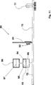
Bei geschlossenem Auslassventil
Die Dosierkapillaren
Zur Dosierung von Medikamentenvolumina wird mit der Pumpe
Die
Die Pumpe
Die weiche Zwischenkammer
In den
In
Eine vorteilhafte Weiterbildung eines in der
Bei einer in der
Bei einem in der
Wenn die Pumpe
Claims (11)
Priority Applications (4)
| Application Number | Priority Date | Filing Date | Title |
|---|---|---|---|
| DE102005045393.7A DE102005045393B4 (en) | 2005-09-23 | 2005-09-23 | Method for dosing solutions |
| US11/424,661 US7985198B2 (en) | 2005-09-23 | 2006-06-16 | Device and process for metering solutions |
| GB0618122A GB2430428B (en) | 2005-09-23 | 2006-09-14 | Device and method for the metering of solutions |
| FR0608232A FR2891151B1 (en) | 2005-09-23 | 2006-09-20 | DEVICE AND METHOD FOR DETERMINING SOLUTIONS |
Applications Claiming Priority (1)
| Application Number | Priority Date | Filing Date | Title |
|---|---|---|---|
| DE102005045393.7A DE102005045393B4 (en) | 2005-09-23 | 2005-09-23 | Method for dosing solutions |
Publications (2)
| Publication Number | Publication Date |
|---|---|
| DE102005045393A1 DE102005045393A1 (en) | 2007-04-05 |
| DE102005045393B4 true DE102005045393B4 (en) | 2017-01-05 |
Family
ID=37309933
Family Applications (1)
| Application Number | Title | Priority Date | Filing Date |
|---|---|---|---|
| DE102005045393.7A Expired - Fee Related DE102005045393B4 (en) | 2005-09-23 | 2005-09-23 | Method for dosing solutions |
Country Status (4)
| Country | Link |
|---|---|
| US (1) | US7985198B2 (en) |
| DE (1) | DE102005045393B4 (en) |
| FR (1) | FR2891151B1 (en) |
| GB (1) | GB2430428B (en) |
Families Citing this family (11)
| Publication number | Priority date | Publication date | Assignee | Title |
|---|---|---|---|---|
| ITBO20080441A1 (en) * | 2008-07-11 | 2010-01-12 | Medica S R L | EQUIPMENT FOR INFUSION OF MEDICINAL SUBSTANCES |
| MX2012000100A (en) * | 2009-07-01 | 2012-04-02 | Fresenius Med Care Hldg Inc | Drug delivery devices and related systems and methods. |
| EP2671176B1 (en) | 2011-01-31 | 2019-01-09 | Fresenius Medical Care Holdings, Inc. | Preventing over-delivery of drug |
| CN106902406B (en) | 2011-02-08 | 2019-11-08 | 弗雷塞尼斯医疗保健控股公司 | Magnetic sensors and related systems and methods |
| US9144646B2 (en) | 2012-04-25 | 2015-09-29 | Fresenius Medical Care Holdings, Inc. | Vial spiking devices and related assemblies and methods |
| US20140088345A1 (en) * | 2012-09-27 | 2014-03-27 | Palo Alto Research Center Incorporated | Single channel, multiple drug delivery device and methods |
| US10076751B2 (en) | 2013-12-30 | 2018-09-18 | General Electric Company | Systems and methods for reagent storage |
| US9399216B2 (en) | 2013-12-30 | 2016-07-26 | General Electric Company | Fluid transport in microfluidic applications with sensors for detecting fluid presence and pressure |
| DE102018217744A1 (en) * | 2018-10-17 | 2020-04-23 | Robert Bosch Gmbh | Method for conveying at least a first medium within a channel system of a microfluidic device |
| CA3113560A1 (en) * | 2018-10-19 | 2020-04-23 | F. Hoffmann-La Roche Ag | Microdosing |
| DE102023121091A1 (en) | 2023-08-08 | 2025-02-13 | B. Braun Melsungen Aktiengesellschaft | Multiplex infusion system with control device, catheter and storage unit for such a multiplex infusion system |
Citations (4)
| Publication number | Priority date | Publication date | Assignee | Title |
|---|---|---|---|---|
| US4687475A (en) * | 1984-06-12 | 1987-08-18 | I-Flow Corporation | Method for sequential intravenous infusion of multiple fluids |
| DE4320365A1 (en) * | 1993-06-19 | 1994-12-22 | Draegerwerk Ag | Multi-channel dosing system |
| DE3850267T2 (en) * | 1987-08-07 | 1995-02-02 | Baxter Int | Closed conveyor system for several liquids. |
| US5640995A (en) * | 1995-03-14 | 1997-06-24 | Baxter International Inc. | Electrofluidic standard module and custom circuit board assembly |
Family Cites Families (5)
| Publication number | Priority date | Publication date | Assignee | Title |
|---|---|---|---|---|
| DE2855713C2 (en) * | 1978-12-22 | 1983-09-22 | Manfred Dr.med. 2000 Hamburg Doehn | Device for infusing solutions from several infusion bottles |
| US5207642A (en) * | 1987-08-07 | 1993-05-04 | Baxter International Inc. | Closed multi-fluid delivery system and method |
| DE10308401A1 (en) * | 2003-02-27 | 2004-09-23 | Dräger Medical AG & Co. KGaA | Device for dosing medicinal substances |
| WO2005007223A2 (en) * | 2003-07-16 | 2005-01-27 | Sasha John | Programmable medical drug delivery systems and methods for delivery of multiple fluids and concentrations |
| DE102004010062B3 (en) * | 2004-03-02 | 2005-09-08 | Drägerwerk AG | Device for dosing substances |
-
2005
- 2005-09-23 DE DE102005045393.7A patent/DE102005045393B4/en not_active Expired - Fee Related
-
2006
- 2006-06-16 US US11/424,661 patent/US7985198B2/en not_active Expired - Fee Related
- 2006-09-14 GB GB0618122A patent/GB2430428B/en not_active Expired - Fee Related
- 2006-09-20 FR FR0608232A patent/FR2891151B1/en not_active Expired - Fee Related
Patent Citations (4)
| Publication number | Priority date | Publication date | Assignee | Title |
|---|---|---|---|---|
| US4687475A (en) * | 1984-06-12 | 1987-08-18 | I-Flow Corporation | Method for sequential intravenous infusion of multiple fluids |
| DE3850267T2 (en) * | 1987-08-07 | 1995-02-02 | Baxter Int | Closed conveyor system for several liquids. |
| DE4320365A1 (en) * | 1993-06-19 | 1994-12-22 | Draegerwerk Ag | Multi-channel dosing system |
| US5640995A (en) * | 1995-03-14 | 1997-06-24 | Baxter International Inc. | Electrofluidic standard module and custom circuit board assembly |
Also Published As
| Publication number | Publication date |
|---|---|
| GB2430428A (en) | 2007-03-28 |
| GB2430428B (en) | 2008-05-28 |
| GB0618122D0 (en) | 2006-10-25 |
| FR2891151A1 (en) | 2007-03-30 |
| US20070073273A1 (en) | 2007-03-29 |
| DE102005045393A1 (en) | 2007-04-05 |
| US7985198B2 (en) | 2011-07-26 |
| FR2891151B1 (en) | 2016-12-02 |
Similar Documents
| Publication | Publication Date | Title |
|---|---|---|
| EP0951308B1 (en) | Medicament dosing system | |
| DE102012209314B4 (en) | Device and method for dispensing or receiving a liquid volume | |
| DE69006721T2 (en) | MICRO PUMP WITH IMPROVED VENTILATION. | |
| EP2060287B1 (en) | Drug supply system for CED (Convection Enhanced Delivery) catheter infusions | |
| DE69100844T2 (en) | PROGRAMMABLE VALVE PUMP. | |
| EP1448252B1 (en) | Medical pump device | |
| DE102005045393B4 (en) | Method for dosing solutions | |
| DE3215330A1 (en) | INFUSION APPARATUS | |
| DE2829215A1 (en) | MEDICAL INFUSION DEVICE WITH PUMP | |
| AT412945B (en) | DEVICE FOR DOSED DISPENSING OF LIQUID | |
| DE69935528T2 (en) | FLOW CONTROL | |
| DE3343708A1 (en) | METHOD AND DEVICE FOR DISPENSING AN INFUSION AGENT TO A BODY OF A MAMMAL | |
| DE102020210536A1 (en) | Microfluidic Device | |
| EP2097722B1 (en) | Device and method for metering media | |
| EP0997643B1 (en) | Diaphragm metering pump | |
| DE102004051537B4 (en) | Dosing system for fluid media | |
| EP1745812A1 (en) | Valve for a fluid, in particular for being used in a mechanically actuated liquid pump | |
| DE102007010412B4 (en) | Device and method for dosing liquids into gas-filled rooms | |
| EP0749330A1 (en) | Micro-infusion system | |
| DE102011003615B4 (en) | Method and device for measuring a volume flow of a liquid flowing into a container and/or a volume of the liquid flowing into the container | |
| DE102009001612B4 (en) | Method and apparatus for generating constant pulsation-free fluid streams for microfluidic applications | |
| DE102008016549A1 (en) | Dosing apparatus for contact free dispensing of liquids, has channel module for collecting and dispensing liquid by capillary and regulated pressure system for generation of over pressure | |
| DE102021109076A1 (en) | Metering device and method for metering liquid media | |
| DE3688077T2 (en) | Flow sensor. | |
| DE202007014392U1 (en) | Device for the metered filling of media |
Legal Events
| Date | Code | Title | Description |
|---|---|---|---|
| OP8 | Request for examination as to paragraph 44 patent law | ||
| 8127 | New person/name/address of the applicant |
Owner name: DRAEGER MEDICAL GMBH, 23558 LUEBECK, DE |
|
| R081 | Change of applicant/patentee |
Owner name: DRAEGER MEDICAL GMBH, DE Free format text: FORMER OWNER: DRAEGER MEDICAL AG & CO. KG, 23558 LUEBECK, DE Effective date: 20110201 Owner name: DRAEGERWERK AG & CO. KGAA, DE Free format text: FORMER OWNER: DRAEGER MEDICAL AG & CO. KG, 23558 LUEBECK, DE Effective date: 20110201 |
|
| R081 | Change of applicant/patentee |
Owner name: DRAEGERWERK AG & CO. KGAA, DE Free format text: FORMER OWNER: DRAEGER MEDICAL GMBH, 23558 LUEBECK, DE |
|
| R016 | Response to examination communication | ||
| R016 | Response to examination communication | ||
| R018 | Grant decision by examination section/examining division | ||
| R020 | Patent grant now final | ||
| R119 | Application deemed withdrawn, or ip right lapsed, due to non-payment of renewal fee |