DE102005044500A1 - Surrounding detecting device for towing vehicle, has control device designed such that obstacle sensors are selectively activatable in trailer mode depending on bend angle between towing vehicle and trailer - Google Patents
Surrounding detecting device for towing vehicle, has control device designed such that obstacle sensors are selectively activatable in trailer mode depending on bend angle between towing vehicle and trailer Download PDFInfo
- Publication number
- DE102005044500A1 DE102005044500A1 DE102005044500A DE102005044500A DE102005044500A1 DE 102005044500 A1 DE102005044500 A1 DE 102005044500A1 DE 102005044500 A DE102005044500 A DE 102005044500A DE 102005044500 A DE102005044500 A DE 102005044500A DE 102005044500 A1 DE102005044500 A1 DE 102005044500A1
- Authority
- DE
- Germany
- Prior art keywords
- sensors
- obstacle
- trailer
- towing vehicle
- activated
- Prior art date
- Legal status (The legal status is an assumption and is not a legal conclusion. Google has not performed a legal analysis and makes no representation as to the accuracy of the status listed.)
- Granted
Links
- 230000005540 biological transmission Effects 0.000 claims abstract description 26
- 238000000034 method Methods 0.000 claims abstract description 7
- 238000005452 bending Methods 0.000 claims description 19
- 238000001514 detection method Methods 0.000 claims description 19
- 238000005516 engineering process Methods 0.000 claims description 3
- 230000002093 peripheral effect Effects 0.000 claims description 3
- 230000007613 environmental effect Effects 0.000 claims 1
- 238000005259 measurement Methods 0.000 description 12
- 230000008878 coupling Effects 0.000 description 2
- 238000010168 coupling process Methods 0.000 description 2
- 238000005859 coupling reaction Methods 0.000 description 2
- 230000001419 dependent effect Effects 0.000 description 2
- 241000881711 Acipenser sturio Species 0.000 description 1
- 206010009691 Clubbing Diseases 0.000 description 1
- 230000009471 action Effects 0.000 description 1
- 230000004913 activation Effects 0.000 description 1
- 238000013459 approach Methods 0.000 description 1
- 230000000694 effects Effects 0.000 description 1
- 238000011156 evaluation Methods 0.000 description 1
- 230000002349 favourable effect Effects 0.000 description 1
- 230000003993 interaction Effects 0.000 description 1
- 230000003287 optical effect Effects 0.000 description 1
- 238000012549 training Methods 0.000 description 1
- 238000002604 ultrasonography Methods 0.000 description 1
Classifications
-
- B—PERFORMING OPERATIONS; TRANSPORTING
- B62—LAND VEHICLES FOR TRAVELLING OTHERWISE THAN ON RAILS
- B62D—MOTOR VEHICLES; TRAILERS
- B62D13/00—Steering specially adapted for trailers
- B62D13/06—Steering specially adapted for trailers for backing a normally drawn trailer
-
- B—PERFORMING OPERATIONS; TRANSPORTING
- B62—LAND VEHICLES FOR TRAVELLING OTHERWISE THAN ON RAILS
- B62D—MOTOR VEHICLES; TRAILERS
- B62D15/00—Steering not otherwise provided for
- B62D15/02—Steering position indicators ; Steering position determination; Steering aids
- B62D15/027—Parking aids, e.g. instruction means
-
- G—PHYSICS
- G01—MEASURING; TESTING
- G01S—RADIO DIRECTION-FINDING; RADIO NAVIGATION; DETERMINING DISTANCE OR VELOCITY BY USE OF RADIO WAVES; LOCATING OR PRESENCE-DETECTING BY USE OF THE REFLECTION OR RERADIATION OF RADIO WAVES; ANALOGOUS ARRANGEMENTS USING OTHER WAVES
- G01S13/00—Systems using the reflection or reradiation of radio waves, e.g. radar systems; Analogous systems using reflection or reradiation of waves whose nature or wavelength is irrelevant or unspecified
- G01S13/88—Radar or analogous systems specially adapted for specific applications
- G01S13/93—Radar or analogous systems specially adapted for specific applications for anti-collision purposes
- G01S13/931—Radar or analogous systems specially adapted for specific applications for anti-collision purposes of land vehicles
- G01S2013/9315—Monitoring blind spots
-
- G—PHYSICS
- G01—MEASURING; TESTING
- G01S—RADIO DIRECTION-FINDING; RADIO NAVIGATION; DETERMINING DISTANCE OR VELOCITY BY USE OF RADIO WAVES; LOCATING OR PRESENCE-DETECTING BY USE OF THE REFLECTION OR RERADIATION OF RADIO WAVES; ANALOGOUS ARRANGEMENTS USING OTHER WAVES
- G01S13/00—Systems using the reflection or reradiation of radio waves, e.g. radar systems; Analogous systems using reflection or reradiation of waves whose nature or wavelength is irrelevant or unspecified
- G01S13/88—Radar or analogous systems specially adapted for specific applications
- G01S13/93—Radar or analogous systems specially adapted for specific applications for anti-collision purposes
- G01S13/931—Radar or analogous systems specially adapted for specific applications for anti-collision purposes of land vehicles
- G01S2013/9317—Driving backwards
Landscapes
- Engineering & Computer Science (AREA)
- Chemical & Material Sciences (AREA)
- Combustion & Propulsion (AREA)
- Transportation (AREA)
- Mechanical Engineering (AREA)
- Control Of Driving Devices And Active Controlling Of Vehicle (AREA)
- Traffic Control Systems (AREA)
Abstract
Description
Die Erfindung betrifft eine Umfelderkennungseinrichtung für ein Zugfahrzeug mit einer Steuerungseinrichtung und einem oder mehreren Hindernissensoren sowie ein Verfahren zur Ansteuerung der Umfelderkennungseinrichtung.The The invention relates to an environment detection device for a towing vehicle with a control device and one or more obstacle sensors and a method for controlling the surroundings detection device.
Für den Fahrer eines Zugfahrzeugs mit Anhänger ist es eine schwierige Aufgabe, rückwärts an eine Laderampe oder an ein Hindernis heran zu fahren. Der für den Fahrer einsehbare rückwärtige Raum wird durch ein Zusammenspiel der Länge und Breite des Zugfahrzeugs und des Anhängers in Kombination mit den für die Rundumsicht verantwortlichen Spiegel bestimmt. Im allgemeinen wird die Umgebung hinter dem Zugfahrzeug umso unübersichtlicher je größer der Knickwinkel zwischen Zugfahrzeug und Anhänger ist.For the driver a towing vehicle with a trailer It is a difficult task, backwards to a loading dock or to approach an obstacle. The rear viewable for the driver is due to an interaction of the length and width of the towing vehicle and the trailer in combination with the for the all-round view responsible mirror determines. In general the larger the environment behind the towing vehicle the more confusing Bending angle between towing vehicle and trailer is.
Es ist üblich zur Unterstützung des Fahrers im Heckbereich eines Fahrzeugs Hindernissensoren anzuordnen. Diese Technologie ist bei Personenkraftfahrzeugen mittlerweile auf dem Markt weit verbreitet. Allerdings weist ein an ein Zugfahrzeug mit rückwärtig ausgerichteten Hindernissensoren angekoppelter Anhänger im Bereich der Sensorreichweite viele Störkonturen wie z.B. Stützbeine, Ablageflächen etc. auf, die von den Hindernissensoren als Hindernis erkannt werden und zur Ausgabe eines Warnsignals führen. Zur Vermeidung eines ständig an den Fahrer weitergegebenes Warnsignal werden die Hindernissensoren üblicherweise abgeschaltet, sobald der Anhänger angekoppelt ist.It is common for support To arrange the driver in the rear of a vehicle obstacle sensors. This technology is now on in passenger vehicles widely used by the market. However, one points to a towing vehicle with rearward facing Obstacle sensors of coupled trailers in the range of the sensor range many sturgeon contours such as. Support legs, shelves etc., which are recognized by the obstacle sensors as an obstacle and lead to the issuing of a warning signal. To avoid a constantly the warning signal transmitted to the driver usually becomes the obstacle sensors shut off as soon as the trailer is coupled.
Die
Druckschrift
Der Erfindung liegt deshalb die Aufgabe zugrunde, eine Umfelderkennungseinrichtung vorzuschlagen, welche den rückwärtigen Raum eines Zugfahrzeugs mit angekoppeltem Anhänger insbesondere beim Rückwärtsfahren effektiv überwacht. Ergänzend soll ein Verfahren zur Ansteuerung der Umfelderkennungseinrichtung gebildet werden.Of the The invention is therefore based on the object, an environment detection device to suggest which the rear room a towing vehicle with coupled trailer especially when reversing effectively monitored. additional is a method for controlling the environment detection device be formed.
Diese Aufgabe wird durch eine Umfelderkennungseinrichtung mit den Merkmalen des Anspruchs 1 sowie mit einem Verfahren mit den Merkmalen des Anspruchs 12 gelöst. Vorteilhafte Ausgestaltungen der Erfindung ergeben sich aus den Unteransprüchen.These Task is by an environment detection device with the features of claim 1 and a method with the features of Claim 12 solved. Advantageous embodiments of the invention will become apparent from the Dependent claims.
Die Umfelderkennungseinrichtung ist für ein Zugfahrzeug geeignet und/oder ausgebildet, wobei als Zugfahrzeug vorzugsweise jede Art von Fahrzeug verstanden wird, an das ein Anhänger oder Auflieger koppelbar ist, insbesondere wird darunter eine Sattelzugmaschine verstanden.The Environment recognition device is suitable for a towing vehicle and / or formed, wherein as a towing vehicle preferably any kind is understood by the vehicle to which a trailer or semi-trailer coupled is, in particular, a tractor unit understood.
Die erfindungsgemäße Umfelderkennungseinrichtung weist eine Steuerungseinrichtung und einen oder mehrere Hindernissensoren auf. Die Hindernissensoren sind zur Erfassung des Abstandes eines Hindernisses in einem vorgegebenen Bereich ausgebildet. Prinzipiell können die Hindernissensoren als beliebige Sensoren, z.B. als Ultraschall-, Radar- und/oder Lasersensoren etc. ausgebildet sein.The Inventive detection device according to the invention has a controller and one or more obstacle sensors on. The obstacle sensors are for detecting the distance of a Obstacle formed in a given area. in principle can the obstacle sensors as any sensors, e.g. as ultrasonic, Radar and / or laser sensors, etc. may be formed.
Bevorzugt sind die Hindernissensoren jedoch als nach dem Echolot-Prinzip arbeitende Sensoren, insbesondere als Ultraschallsensoren und/oder Radarsensoren realisiert.Prefers However, the obstacle sensors are working as a sonar principle Sensors, in particular as ultrasonic sensors and / or radar sensors realized.
Bei dem Echolot-Prinzip werden die Hindernissensoren vorzugsweise zeitlich versetzt und insbesondere zyklisch vom Steuergerät angesprochen, wobei der jeweils angesprochene Hindernissensor ein Echosignal, insbesondere ein Ultraschallpaket, aussendet. Die Entfernung zum Hindernis und/oder die Position des Hindernisses kann in Kenntnis der gemessenen Laufzeit des Echosignals und der Schallgeschwindigkeit mittels eines Triangulationsverfahrens in bekannter weise ermittelt werden, wobei eine Direktmessung und eine Kreuzmessung benötigt wird. Direktmessung bedeutet, dass ein Hindernissensor ein Signal sendet und sein eigenes Echo empfängt. Kreuzmessung bedeutet, dass das Echo des vom Hindernissensor gesendeten Signals von einem anderen Hindernissensor empfangen wird. Für eine vollständige Bestimmung der Entfernung und/oder der Position eines Hindernisses nach dem Echolot-Prinzip werden somit mindestens zwei Hindernissensoren benötigt.In the echosounding principle, the obstacle sensors are preferably offset in time and, in particular, cyclically addressed by the control unit, wherein the respectively addressed obstacle sensor emits an echo signal, in particular an ultrasound packet. The distance to the obstacle and / or the position of the obstacle can be determined with knowledge of the measured transit time of the echo signal and the speed of sound by means of a triangulation method in a known manner, wherein a direct measurement and a Cross measurement is needed. Direct measurement means that an obstacle sensor sends a signal and receives its own echo. Cross measurement means that the echo of the signal transmitted by the obstacle sensor is received by another obstacle sensor. For a complete determination of the distance and / or the position of an obstacle according to the sonar principle, at least two obstacle sensors are thus required.
Die Steuerungseinrichtung ist mit den Hindernissensoren verschaltet und vorzugsweise mit insbesondere optischen, akustischen oder haptischen Warneinrichtungen gekoppelt und/oder koppelbar.The Control device is connected to the obstacle sensors and preferably with in particular optical, acoustic or haptic Warning devices coupled and / or coupled.
Erfindungsgemäß ist vorgesehen, dass im Anhängerbetrieb der oder die Hindernissensoren in Abhängigkeit des Knickwinkels zwischen dem Zugfahrzeug und einem Anhänger selektiv aktivierbar und/oder aktiviert sind.According to the invention, it is provided that in trailer operation the obstacle or sensors depending on the bending angle between the towing vehicle and a trailer are selectively activated and / or activated.
Als Knickwinkel wird dabei der Winkel zwischen der Längserstreckungsrichtung des Zugfahrzeugs und der Längserstreckungsrichtung des Anhängers verstanden. Sind beispielsweise Zugfahrzeug und Anhänger in Geradeausfahrt hintereinander angeordnet, so beträgt der Knickwinkel 0°.When Buckling angle is the angle between the longitudinal direction of the Towing vehicle and the longitudinal direction of the trailer Understood. For example, are towing vehicle and trailer in Straight ahead, arranged one behind the other, the angle of articulation is 0 °.
Die Hindernissensoren werden von der Steuerungseinrichtung angesteuert, insbesondere einzeln und/oder nacheinander zu- bzw. abgeschaltet, wobei die Auswahl der Hindernissensoren in Abhängigkeit des Knickwinkels erfolgt. Insbesondere kann die selektive Aktivierung physikalisch, also durch Zu- und/oder Abschalten von Hindernissensoren und/oder Teilen von Hindernissensoren und/oder von Messbereichsabschnitten bei der Messwertaufnahme, oder informationstechnisch, also durch Zu- und/oder Abschalten von Hindernissensoren und/oder Teilen von Hindernissensoren und/oder von Messbereichsabschnitten bei der Messwertauswertung, realisiert sein.The Obstacle sensors are controlled by the control device, in particular individually and / or successively switched on or off, wherein the selection of the obstacle sensors is done in dependence of the bending angle. In particular, the selective activation can be physical, ie by Switching on and / or off obstacle sensors and / or parts of Obstacle sensors and / or measuring range sections during the measurement recording, or information technology, ie by switching on and / or off Obstacle sensors and / or parts of obstacle sensors and / or of measuring range sections during measured value evaluation be.
Vorzugsweise werden die Hindernissensoren insbesondere physikalisch derart zu- bzw. abgeschaltet, so dass Hindernissensorpaare gebildet werden, die eine Kreuzortung in den gewünschten Raumbereichen ermöglichen.Preferably In particular, the obstacle sensors are physically so or switched off, so that obstacle sensor pairs are formed, the one cross locating in the desired Allow room areas.
Die Erfindung geht dabei von der Überlegung aus, dass die Hindernissensoren jeweils für freie Raumbereiche hinter dem Zugfahrzeug zugeschaltet werden, die nicht durch den Anhänger verdeckt sind, wobei die freien Raumbereiche über den Knickwinkel zwischen Zugfahrzeug und Anhänger ermittelt werden.The Invention is based on the consideration out that the obstacle sensors each for free space areas behind the towing vehicle are switched, which are not covered by the trailer are, with the free space above the bending angle between Towing vehicle and trailer be determined.
Bei einer weiteren bevorzugten Ausführungsform der Erfindung weisen die Hindernissensoren jeweils ein Sendemodul zum Aufbau eines räumlichen Sendebereichs und ein Empfangsmodul zum Aufbau eines räumlichen Empfangsbereichs auf. Vorzugsweise sind Sendebereich und Empfangsbereich keulenförmig ausgebildet.at a further preferred embodiment According to the invention, the obstacle sensors each have a transmission module to build a spatial Transmit area and a receiving module to build a spatial Reception area. Preferably, the transmission range and the reception range are lobar educated.
Bei einer bevorzugten Ausführungsform der Erfindung sind die Sendemodule und Empfangsmodule selektiv durch die Steuerungseinrichtung aktivierbar und/oder aktiviert, insbesondere derart, dass ein Hindernissensor im Betrieb ein aktiviertes Sendemodul und ein deaktiviertes Empfangsmodul oder vice versa aufweisen kann.at a preferred embodiment In accordance with the invention, the transmit modules and receive modules are selectively through the control device can be activated and / or activated, in particular such that an obstacle sensor in operation an activated transmission module and may have a deactivated receiving module or vice versa.
Das
selektive Zuschalten von Hindernissensoren und/oder Sendemodulen
und/oder Empfangsmodulen durch die Steuerungseinrichtung erfolgt
vorzugsweise in den folgenden Situationen:
Ein Hindernissensor
wird vollständig,
d.h. mit Sendemodul und Empfangsmodul, zugeschaltet, sobald der Knickwinkel
derart ausgebildet ist, dass der Anhänger außerhalb des Sendebereichs und
zugleich außerhalb des
Empfangsbereichs des Hindernissensors angeordnet ist. In diesem
Fall kann der zugeschaltete Hindernissensor eine Direktmessung sowie
eine Kreuzmessung mit einem insbesondere benachbarten, anderem Hindernissensor
vornehmen.The selective connection of obstacle sensors and / or transmission modules and / or receiving modules by the control device preferably takes place in the following situations:
An obstacle sensor is switched on completely, ie with the transmission module and the reception module, as soon as the articulation angle is such that the trailer is arranged outside the transmission range and at the same time outside the reception range of the obstacle sensor. In this case, the connected obstacle sensor can make a direct measurement as well as a cross measurement with a particular adjacent obstacle sensor.
Das Sendemodul eines Hindernissensors wird zugeschaltet, sobald der Knickwinkel derart ausgebildet ist, dass der Anhänger außerhalb des Sendebereichs des Hindernissensors angeordnet ist.The Transmitter module of an obstacle sensor is switched on as soon as the Bent angle is designed such that the trailer outside the transmission range of the Obstruction sensor is arranged.
Das Empfangsmodul eines Hindernissensors wird zugeschaltet, sobald der Knickwinkel derart ausgebildet ist, dass zumindest ein Sendemodul eines anderen Hindernissensors aktiviert ist und der Empfangsbereich des zugeschalteten Hindernissensors zumindest teilweise mit dem Sendebereich des aktivierten Sendemoduls des anderen Hindernissensors überlappt. Zugleich kann der Empfangsbereich des zugeschalteten Hindernissensors auch mit dem Anhänger überlappen.The Reception module of an obstacle sensor is activated as soon as the Bent angle is designed such that at least one transmission module another obstacle sensor is activated and the reception area the switched obstacle sensor at least partially with the The transmission range of the activated transmission module of the other obstacle sensor overlaps. At the same time, the reception area of the connected obstacle sensor also overlap with the trailer.
Soweit vorliegend von Empfangs- und Sendebereichen gesprochen wird, werden damit die für eine Hindernismessung technisch relevanten, räumlichen und keine theoretisch unendlich ausgedehnten Bereiche bezeichnet.So far is spoken in this case of receiving and transmitting areas are with it for an obstacle measurement technically relevant, spatial and not theoretical denotes infinitely extended areas.
Bei einer bevorzugten Ausführungsform der Erfindung sind die Hindernissensoren als eine im wesentlichen waagrecht ausgerichtete Anordnung am Heck des Zugfahrzeugs ausgebildet. Vorzugsweise werden mindestens vier Hindernissensoren verwendet, wobei jeweils zwei Hindernissensoren im Randbereich der Anordnung konzentriert sind, so dass sich im Randbereich ein Raumbereich für die Hindernismessung ausbildet, in dem sowohl eine Kreuz- als auch eine Direktmessung durchführbar ist.at a preferred embodiment According to the invention, the obstacle sensors are essentially one horizontally aligned arrangement formed at the rear of the towing vehicle. Preferably, at least four obstacle sensors are used in each case two obstacle sensors in the edge region of the arrangement are concentrated, so that in the border area a space area for the obstacle measurement training, in which both a cross and a direct measurement feasible is.
Bei einer bevorzugten Ausführungsform sind die randseitigen Hindernissensoren im wesentlichen senkrecht übereinander, insbesondere lotrecht übereinander, angeordnet und/oder zueinander versetzt angeordnet, wobei vorzugsweise die Hauptmessrichtungen der Hindernissensoren aufeinander zulaufend ausgebildet sind.at a preferred embodiment the peripheral obstacle sensors are substantially perpendicular to one another, especially one above the other, arranged and / or arranged offset to one another, preferably the main measuring directions of the obstacle sensors converge are formed.
Bei dem erfindungsgemäßen Verfahren ist vorgesehen, dass die Hindernissensoren selektiv entweder vollständig, also mit der Funktion „Senden und Empfangen", oder alternativ abhängig vom Knickwinkel vollständig oder nur im Empfangsbetrieb, also mit der Funktion „Nur Empfangen", aktiviert werden.at the method according to the invention It is envisaged that the obstacle sensors will be selectively either completely, ie with the function "Send and receiving ", or alternatively dependent from the bending angle completely or only in receive mode, ie with the function "receive only".
Weitere Einzelheiten, Merkmale, Merkmalskombinationen, Vorteile und Wirkungen auf der Basis der Erfindung ergeben sich aus der nachfolgenden Beschreibung der bevorzugten Ausführungsbeispiele der Erfindung und aus den Zeichnungen. Diese zeigen jeweils in schematischer Darstellung:Further Details, features, feature combinations, benefits and effects on the basis of the invention will become apparent from the following description the preferred embodiments the invention and from the drawings. These show each in more schematic Presentation:
Einander entsprechende Teile oder Größen sind in den Figuren jeweils mit denselben Bezugszeichen versehen.each other corresponding parts or sizes are each provided with the same reference numerals in the figures.
Zugfahrzeug
Die
hellen Sichtbereiche
In
der
Das
Zugfahrzeug
Die
acht Sensoren S1 ... S8 sind mit einer Steuerungseinrichtung
Ausgehend von jedem der acht Sensoren S1 ... S8 erstreckt sich jeweils ein keulenförmiger Sende- und Empfangsbereich B1 ... B8, die gegenseitig überlappend angeordnet sind. Die Hauptmessrichtungen der Sensoren S1 bis S3 bzw. S4 und S5 bzw. S6 bis S8 sind jeweils parallel oder im wesentlichen parallel zueinander ausgerichtet.outgoing Each of the eight sensors S1... S8 extends in each case clubbed Transmit and receive range B1 ... B8, which overlap each other are arranged. The main measuring directions of the sensors S1 to S3 or S4 and S5 or S6 to S8 are respectively parallel or substantially aligned parallel to each other.
Fahrzeug
Die
Funktionsweise der Umfelderkennungseinrichtung ist wie folgt: Der
Knickwinkel alpha = 5° wird z.B.
von einem Sensor erfasst und der Steuerungseinrichtung
Die
In
der
Sensors
S3 vollständig
ausgeschwenkt. Die Steuerungseinrichtung aktiviert in dieser Situation
den Sensor S3 und zwar für
den sende- und Empfangsbetrieb. Optional kann der Sensor S2 abgeschaltet
werden, so dass die Kreuzmessung von den Sensoren S1 und S3 durchgeführt wird.
Die Sensoren S1 und S3 werden zyklisch nacheinander von der Steuerungseinrichtung
Bei
einem Knickwinkel von alpha ≥ 50° (
Bei
einer alternativen Ausführungsform
der Ansteuerung werden die Sensoren S1 ... S8 nicht nur jeweils
vollständig,
d.h. jeweils gleichzeitig für
den Sende- und Empfangsbetrieb, aktiviert, sondern in Abhängigkeit
des Knickwinkels wird nur das Empfangsmodul eines Sensors aktiviert,
wobei das Sendemodul deaktiviert ist. Die Sensoren werden also gemäß der Funktionen „senden
und empfangen" und „nur empfangen" angesteuert. Eine
derartige alternative Ansteuerung der Sensoren S1 ... S8 ist in
der nachfolgenden Tabelle dargelegt: 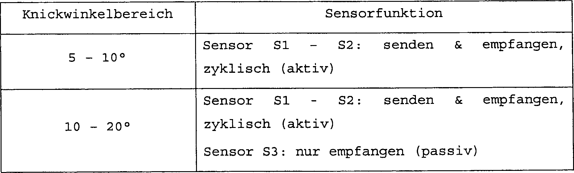

Optional kann auch bei dieser Ansteuerung der Sensor S2 bei einem Knickwinkel alpha > 20° deaktiviert werden.optional can also with this control, the sensor S2 at a bend angle alpha> 20 ° deactivated become.
Die
Im
Unterschied zu dem ersten Ausführungsbeispiel
weist das zweite Ausführungsbeispiel
nur sechs Sensoren U1 ... U6 auf, die zudem anders angeordnet und/oder
ausgerichtet sind als die Sensoren S1 ... S8. Im wesentlichen entsprechen
die Sensoren U1 ... U6 den Sensoren S1, S3 ... S7, wobei die Zusatzsensoren S2
und S8 in dem zweiten Ausführungsbeispiel
entfallen sind. Um einen ausreichend überlappenden Sende- und Empfangsbereich
im Randbereich des Hecks des Fahrzeugs
Die
Ansteuerung des zweiten Ausführungsbeispiels
erfolgt gemäß der nachfolgenden
Tabelle.

Dieses
zweite Ausführungsbeispiel
ist günstiger
in der Umsetzung, da zum einen weniger Sensoren benötigt werden
und zum zweiten die Steuerungseinrichtung einfacher ausgeführt werden
kann. Bei einer vereinfachten Ausführung der Umfelderkennungseinrichtung
kann vorgesehen sein, die Sensoren S5 und S4 bzw. U3 und U4 in den
jeweiligen Ausführungsbeispielen
einzusparen und somit im wesentlichen nur die Randbereiche des Hecks
des Fahrzeugs
- 11
- Zugfahrzeugtowing vehicle
- 22
- Anhängerpendant
- 3a, b, c, d3a, b, c, d
- Sichtbereicheviewing areas
- 44
- Kupplungseinrichtungcoupling device
- 55
- Steuerungseinrichtungcontrol device
- 66
- Warneinrichtungwarning device
- S1 ... S8S1 ... S8
- Sensorensensors
- U1 ... U6U1 ... U6
- Sensorensensors
- B1 ... B8B1 ... B8
- Sende- und EmpfangsbereicheSend- and reception areas
- R1 ... R6R1 ... R6
- Sende- und EmpfangsbereicheSend- and reception areas
Claims (12)
Priority Applications (2)
| Application Number | Priority Date | Filing Date | Title |
|---|---|---|---|
| DE102005044500A DE102005044500B4 (en) | 2005-09-16 | 2005-09-16 | Environment detection device for a towing vehicle |
| PCT/EP2006/001385 WO2007033705A1 (en) | 2005-09-16 | 2006-02-16 | Device for detecting surroundings and method for actuating the device for detecting surroundings |
Applications Claiming Priority (1)
| Application Number | Priority Date | Filing Date | Title |
|---|---|---|---|
| DE102005044500A DE102005044500B4 (en) | 2005-09-16 | 2005-09-16 | Environment detection device for a towing vehicle |
Publications (2)
| Publication Number | Publication Date |
|---|---|
| DE102005044500A1 true DE102005044500A1 (en) | 2007-03-29 |
| DE102005044500B4 DE102005044500B4 (en) | 2011-11-10 |
Family
ID=37832432
Family Applications (1)
| Application Number | Title | Priority Date | Filing Date |
|---|---|---|---|
| DE102005044500A Expired - Fee Related DE102005044500B4 (en) | 2005-09-16 | 2005-09-16 | Environment detection device for a towing vehicle |
Country Status (2)
| Country | Link |
|---|---|
| DE (1) | DE102005044500B4 (en) |
| WO (1) | WO2007033705A1 (en) |
Cited By (7)
| Publication number | Priority date | Publication date | Assignee | Title |
|---|---|---|---|---|
| DE102009048380A1 (en) * | 2009-10-06 | 2011-04-07 | GM Global Technology Operations, Inc., Detroit | Parking assistance system for motor vehicle, has connector plugging device whose connection socket is controlled such that automatic switching of vehicle-lateral sensors to trailer sensors is provided by connector plugging device |
| DE102010045657A1 (en) * | 2010-09-17 | 2012-03-22 | Wabco Gmbh | Environment monitoring system for a vehicle |
| WO2014079521A1 (en) * | 2012-11-22 | 2014-05-30 | Wabco Gmbh | Method and device for controlling a rear monitoring system of a vehicle combination |
| EP2983006A1 (en) * | 2014-08-08 | 2016-02-10 | Delphi Technologies, Inc. | Vehicle radar system with trailer detection |
| DE102016015363A1 (en) * | 2016-12-17 | 2018-06-21 | Wabco Gmbh | Method for monitoring a vehicle environment of a vehicle combination, as well as monitoring system |
| DE102018218269A1 (en) * | 2018-10-25 | 2020-04-30 | Robert Bosch Gmbh | Method for operating a vehicle, control device, vehicle |
| US11768284B2 (en) | 2018-10-08 | 2023-09-26 | Aptiv Technologies Limited | Detection system and method |
Families Citing this family (2)
| Publication number | Priority date | Publication date | Assignee | Title |
|---|---|---|---|---|
| DE102015117903A1 (en) | 2015-10-21 | 2017-04-27 | Valeo Schalter Und Sensoren Gmbh | Method for operating a driver assistance system, driver assistance system and motor vehicle |
| US10657823B2 (en) | 2017-10-26 | 2020-05-19 | Bendix Commercial Vehicle Systems Llc | System and method for determining when an object detected by a collision avoidance sensor on one member of an articulated vehicle comprises another member of the vehicle |
Citations (3)
| Publication number | Priority date | Publication date | Assignee | Title |
|---|---|---|---|---|
| DE19805515A1 (en) * | 1998-02-11 | 1999-08-12 | Bayerische Motoren Werke Ag | Obstacle detection system in a motor vehicle |
| DE10037128A1 (en) * | 1999-09-13 | 2001-05-03 | Volkswagen Ag | Method and device for inspecting a vehicle driving path uses a camera linked to a lens or a lens system with electrically adjustable or panning devices for altering focal length and viewing direction of the camera's current position. |
| DE10124909A1 (en) * | 2001-05-22 | 2002-12-19 | Bosch Gmbh Robert | Method and device for operating a radar sensor arrangement |
Family Cites Families (3)
| Publication number | Priority date | Publication date | Assignee | Title |
|---|---|---|---|---|
| DE10312548B3 (en) * | 2003-03-21 | 2004-05-19 | Audi Ag | Vehicle with two symmetrical parking and reversing sensors at rear, employs them when trailer is attached, to detect its relative angle |
| US7301479B2 (en) * | 2003-09-26 | 2007-11-27 | Chrysler Llc | Trailer detection circuit for a vehicle park assist system |
| DE102005019550A1 (en) * | 2005-04-28 | 2006-11-09 | Daimlerchrysler Ag | A distance detection system for a towing vehicle and method for operating a distance detection system |
-
2005
- 2005-09-16 DE DE102005044500A patent/DE102005044500B4/en not_active Expired - Fee Related
-
2006
- 2006-02-16 WO PCT/EP2006/001385 patent/WO2007033705A1/en not_active Ceased
Patent Citations (3)
| Publication number | Priority date | Publication date | Assignee | Title |
|---|---|---|---|---|
| DE19805515A1 (en) * | 1998-02-11 | 1999-08-12 | Bayerische Motoren Werke Ag | Obstacle detection system in a motor vehicle |
| DE10037128A1 (en) * | 1999-09-13 | 2001-05-03 | Volkswagen Ag | Method and device for inspecting a vehicle driving path uses a camera linked to a lens or a lens system with electrically adjustable or panning devices for altering focal length and viewing direction of the camera's current position. |
| DE10124909A1 (en) * | 2001-05-22 | 2002-12-19 | Bosch Gmbh Robert | Method and device for operating a radar sensor arrangement |
Cited By (10)
| Publication number | Priority date | Publication date | Assignee | Title |
|---|---|---|---|---|
| DE102009048380A1 (en) * | 2009-10-06 | 2011-04-07 | GM Global Technology Operations, Inc., Detroit | Parking assistance system for motor vehicle, has connector plugging device whose connection socket is controlled such that automatic switching of vehicle-lateral sensors to trailer sensors is provided by connector plugging device |
| DE102010045657A1 (en) * | 2010-09-17 | 2012-03-22 | Wabco Gmbh | Environment monitoring system for a vehicle |
| US9459347B2 (en) | 2010-09-17 | 2016-10-04 | Wabco Gmbh | Environment monitoring system for a vehicle |
| WO2014079521A1 (en) * | 2012-11-22 | 2014-05-30 | Wabco Gmbh | Method and device for controlling a rear monitoring system of a vehicle combination |
| EP2983006A1 (en) * | 2014-08-08 | 2016-02-10 | Delphi Technologies, Inc. | Vehicle radar system with trailer detection |
| EP3940417A1 (en) * | 2014-08-08 | 2022-01-19 | Aptiv Technologies Limited | Vehicle radar system with trailer detection |
| DE102016015363A1 (en) * | 2016-12-17 | 2018-06-21 | Wabco Gmbh | Method for monitoring a vehicle environment of a vehicle combination, as well as monitoring system |
| US10713505B2 (en) | 2016-12-17 | 2020-07-14 | Wabco Europe Bvba | Method for monitoring the vehicle surroundings of a vehicle combination and monitoring system |
| US11768284B2 (en) | 2018-10-08 | 2023-09-26 | Aptiv Technologies Limited | Detection system and method |
| DE102018218269A1 (en) * | 2018-10-25 | 2020-04-30 | Robert Bosch Gmbh | Method for operating a vehicle, control device, vehicle |
Also Published As
| Publication number | Publication date |
|---|---|
| WO2007033705A1 (en) | 2007-03-29 |
| DE102005044500B4 (en) | 2011-11-10 |
Similar Documents
| Publication | Publication Date | Title |
|---|---|---|
| EP0610702B1 (en) | Device for assisting reversing and coupling trailers to motor vehicles | |
| EP1478547B1 (en) | Method for parking a vehicle | |
| EP3394638B1 (en) | Lidar scanning device for a motor vehicle | |
| DE10312548B3 (en) | Vehicle with two symmetrical parking and reversing sensors at rear, employs them when trailer is attached, to detect its relative angle | |
| EP3510463B1 (en) | Sensor array for an autonomously operated utility vehicle and method for surround-view image acquisition | |
| DE19744185B4 (en) | Device for distance measurement by means of ultrasound | |
| DE4338743C2 (en) | Method and device for operating an ultrasonic sensor | |
| DE102010004920A1 (en) | Device for support of coupling trailer to trailer coupling of motor car e.g. passenger car, controls relative movement of trailer coupling of motor car based on determined relative position of trailer coupling of trailer | |
| DE102014118625A1 (en) | Sensor arrangement for a test stand of a driver assistance system of a motor vehicle, test bench and associated method | |
| DE20306787U1 (en) | Device for detecting the angle between a semitrailer tractor and a semitrailer | |
| DE102012106691B4 (en) | Alternative installation of a concealed ultrasonic sensor in the vehicle | |
| EP3081959B1 (en) | Method for determining a respective installation position of at least two sensors of a motor vehicle, control device, driver assistance system and motor vehicle | |
| DE102015200200A1 (en) | An ultrasound measuring system, means of locomotion and method of operating an ultrasound transceiver | |
| DE102005044500A1 (en) | Surrounding detecting device for towing vehicle, has control device designed such that obstacle sensors are selectively activatable in trailer mode depending on bend angle between towing vehicle and trailer | |
| DE102006040879B4 (en) | Parking and reversing aid | |
| EP1293381B1 (en) | System for measuring and displaying the distance between a vehicle and an object, and vehicle bumper | |
| EP2620326B1 (en) | Method and device for supporting a coupling procedure of a trailer | |
| DE102006055372B4 (en) | Vehicle parking assistance system and method | |
| DE102005044485B4 (en) | Obstacle detection device for a towing vehicle and obstacle detection method | |
| DE10349210B4 (en) | System and method for predictively detecting a potential accident object in the automotive field | |
| DE102005062263A1 (en) | Method and device for detecting objects in the surroundings of a vehicle | |
| DE102006043345B4 (en) | Method for carrying out distance measurements as a parking aid in motor vehicles | |
| DE10305935A1 (en) | Device for detecting objects in the environment of a motor vehicle | |
| DE102006021378A9 (en) | Reversing sensor without control unit | |
| DE102009030452A1 (en) | Driver assistance system operating method for vehicle, involves comparing duration of transmitting signals received as cross-echo with given cross echo threshold value, and providing transmitting signals received as cross echo |
Legal Events
| Date | Code | Title | Description |
|---|---|---|---|
| OP8 | Request for examination as to paragraph 44 patent law | ||
| 8127 | New person/name/address of the applicant |
Owner name: DAIMLERCHRYSLER AG, 70327 STUTTGART, DE |
|
| 8127 | New person/name/address of the applicant |
Owner name: DAIMLER AG, 70327 STUTTGART, DE |
|
| R016 | Response to examination communication | ||
| R016 | Response to examination communication | ||
| R018 | Grant decision by examination section/examining division | ||
| R020 | Patent grant now final |
Effective date: 20120211 |
|
| R119 | Application deemed withdrawn, or ip right lapsed, due to non-payment of renewal fee |