DE102005024160B4 - Inner core profile for a vane blade of a turbine - Google Patents
Inner core profile for a vane blade of a turbine Download PDFInfo
- Publication number
- DE102005024160B4 DE102005024160B4 DE102005024160A DE102005024160A DE102005024160B4 DE 102005024160 B4 DE102005024160 B4 DE 102005024160B4 DE 102005024160 A DE102005024160 A DE 102005024160A DE 102005024160 A DE102005024160 A DE 102005024160A DE 102005024160 B4 DE102005024160 B4 DE 102005024160B4
- Authority
- DE
- Germany
- Prior art keywords
- turbine
- core profile
- inner core
- airfoil
- values
- Prior art date
- Legal status (The legal status is an assumption and is not a legal conclusion. Google has not performed a legal analysis and makes no representation as to the accuracy of the status listed.)
- Expired - Lifetime
Links
Images


Classifications
-
- F—MECHANICAL ENGINEERING; LIGHTING; HEATING; WEAPONS; BLASTING
- F02—COMBUSTION ENGINES; HOT-GAS OR COMBUSTION-PRODUCT ENGINE PLANTS
- F02C—GAS-TURBINE PLANTS; AIR INTAKES FOR JET-PROPULSION PLANTS; CONTROLLING FUEL SUPPLY IN AIR-BREATHING JET-PROPULSION PLANTS
- F02C7/00—Features, components parts, details or accessories, not provided for in, or of interest apart form groups F02C1/00 - F02C6/00; Air intakes for jet-propulsion plants
- F02C7/04—Air intakes for gas-turbine plants or jet-propulsion plants
-
- F—MECHANICAL ENGINEERING; LIGHTING; HEATING; WEAPONS; BLASTING
- F01—MACHINES OR ENGINES IN GENERAL; ENGINE PLANTS IN GENERAL; STEAM ENGINES
- F01D—NON-POSITIVE DISPLACEMENT MACHINES OR ENGINES, e.g. STEAM TURBINES
- F01D5/00—Blades; Blade-carrying members; Heating, heat-insulating, cooling or antivibration means on the blades or the members
- F01D5/12—Blades
- F01D5/14—Form or construction
- F01D5/141—Shape, i.e. outer, aerodynamic form
-
- F—MECHANICAL ENGINEERING; LIGHTING; HEATING; WEAPONS; BLASTING
- F01—MACHINES OR ENGINES IN GENERAL; ENGINE PLANTS IN GENERAL; STEAM ENGINES
- F01D—NON-POSITIVE DISPLACEMENT MACHINES OR ENGINES, e.g. STEAM TURBINES
- F01D9/00—Stators
- F01D9/02—Nozzles; Nozzle boxes; Stator blades; Guide conduits, e.g. individual nozzles
-
- B—PERFORMING OPERATIONS; TRANSPORTING
- B22—CASTING; POWDER METALLURGY
- B22C—FOUNDRY MOULDING
- B22C9/00—Moulds or cores; Moulding processes
- B22C9/10—Cores; Manufacture or installation of cores
-
- F—MECHANICAL ENGINEERING; LIGHTING; HEATING; WEAPONS; BLASTING
- F01—MACHINES OR ENGINES IN GENERAL; ENGINE PLANTS IN GENERAL; STEAM ENGINES
- F01D—NON-POSITIVE DISPLACEMENT MACHINES OR ENGINES, e.g. STEAM TURBINES
- F01D5/00—Blades; Blade-carrying members; Heating, heat-insulating, cooling or antivibration means on the blades or the members
- F01D5/12—Blades
- F01D5/14—Form or construction
- F01D5/18—Hollow blades, i.e. blades with cooling or heating channels or cavities; Heating, heat-insulating or cooling means on blades
-
- F—MECHANICAL ENGINEERING; LIGHTING; HEATING; WEAPONS; BLASTING
- F01—MACHINES OR ENGINES IN GENERAL; ENGINE PLANTS IN GENERAL; STEAM ENGINES
- F01D—NON-POSITIVE DISPLACEMENT MACHINES OR ENGINES, e.g. STEAM TURBINES
- F01D9/00—Stators
- F01D9/02—Nozzles; Nozzle boxes; Stator blades; Guide conduits, e.g. individual nozzles
- F01D9/04—Nozzles; Nozzle boxes; Stator blades; Guide conduits, e.g. individual nozzles forming ring or sector
- F01D9/041—Nozzles; Nozzle boxes; Stator blades; Guide conduits, e.g. individual nozzles forming ring or sector using blades
-
- F—MECHANICAL ENGINEERING; LIGHTING; HEATING; WEAPONS; BLASTING
- F01—MACHINES OR ENGINES IN GENERAL; ENGINE PLANTS IN GENERAL; STEAM ENGINES
- F01D—NON-POSITIVE DISPLACEMENT MACHINES OR ENGINES, e.g. STEAM TURBINES
- F01D9/00—Stators
- F01D9/02—Nozzles; Nozzle boxes; Stator blades; Guide conduits, e.g. individual nozzles
- F01D9/04—Nozzles; Nozzle boxes; Stator blades; Guide conduits, e.g. individual nozzles forming ring or sector
- F01D9/047—Nozzle boxes
-
- F—MECHANICAL ENGINEERING; LIGHTING; HEATING; WEAPONS; BLASTING
- F02—COMBUSTION ENGINES; HOT-GAS OR COMBUSTION-PRODUCT ENGINE PLANTS
- F02C—GAS-TURBINE PLANTS; AIR INTAKES FOR JET-PROPULSION PLANTS; CONTROLLING FUEL SUPPLY IN AIR-BREATHING JET-PROPULSION PLANTS
- F02C7/00—Features, components parts, details or accessories, not provided for in, or of interest apart form groups F02C1/00 - F02C6/00; Air intakes for jet-propulsion plants
- F02C7/12—Cooling of plants
-
- F—MECHANICAL ENGINEERING; LIGHTING; HEATING; WEAPONS; BLASTING
- F05—INDEXING SCHEMES RELATING TO ENGINES OR PUMPS IN VARIOUS SUBCLASSES OF CLASSES F01-F04
- F05D—INDEXING SCHEME FOR ASPECTS RELATING TO NON-POSITIVE-DISPLACEMENT MACHINES OR ENGINES, GAS-TURBINES OR JET-PROPULSION PLANTS
- F05D2230/00—Manufacture
- F05D2230/20—Manufacture essentially without removing material
- F05D2230/21—Manufacture essentially without removing material by casting
- F05D2230/211—Manufacture essentially without removing material by casting by precision casting, e.g. microfusing or investment casting
Landscapes
- Engineering & Computer Science (AREA)
- Mechanical Engineering (AREA)
- General Engineering & Computer Science (AREA)
- Chemical & Material Sciences (AREA)
- Combustion & Propulsion (AREA)
- Physics & Mathematics (AREA)
- Fluid Mechanics (AREA)
- Turbine Rotor Nozzle Sealing (AREA)
- Materials For Photolithography (AREA)
- Developing Agents For Electrophotography (AREA)
- Control Of Turbines (AREA)
Abstract
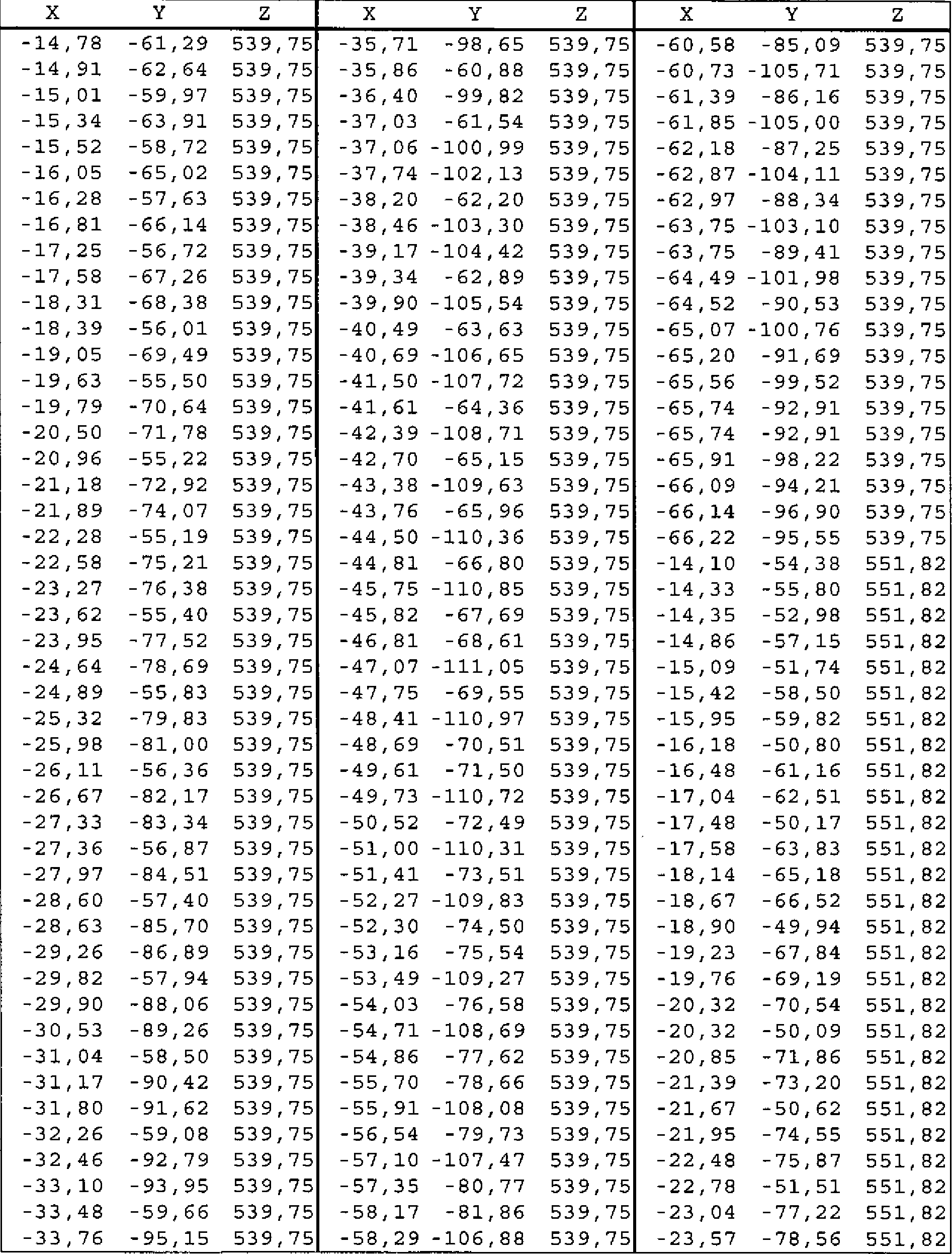
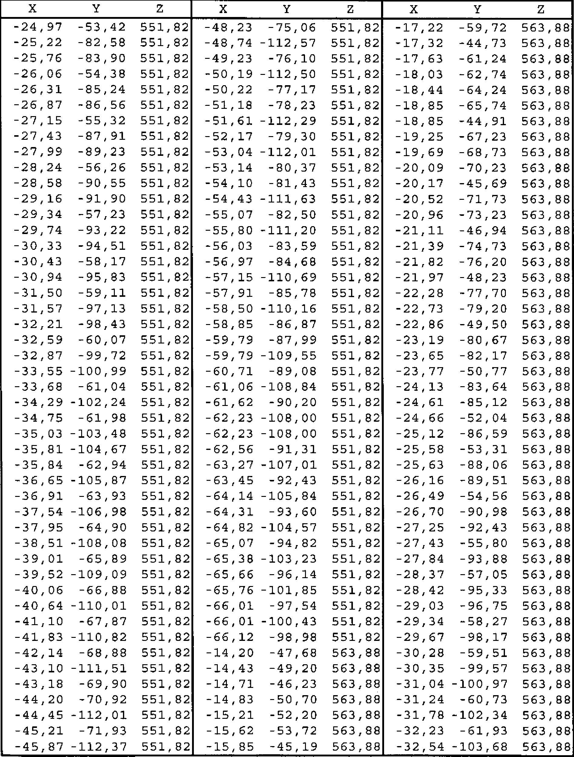
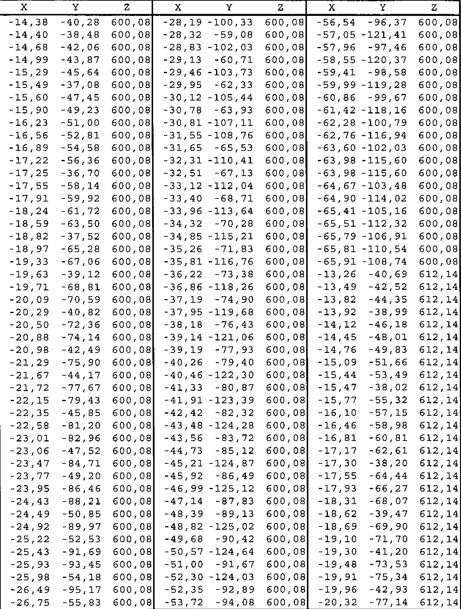
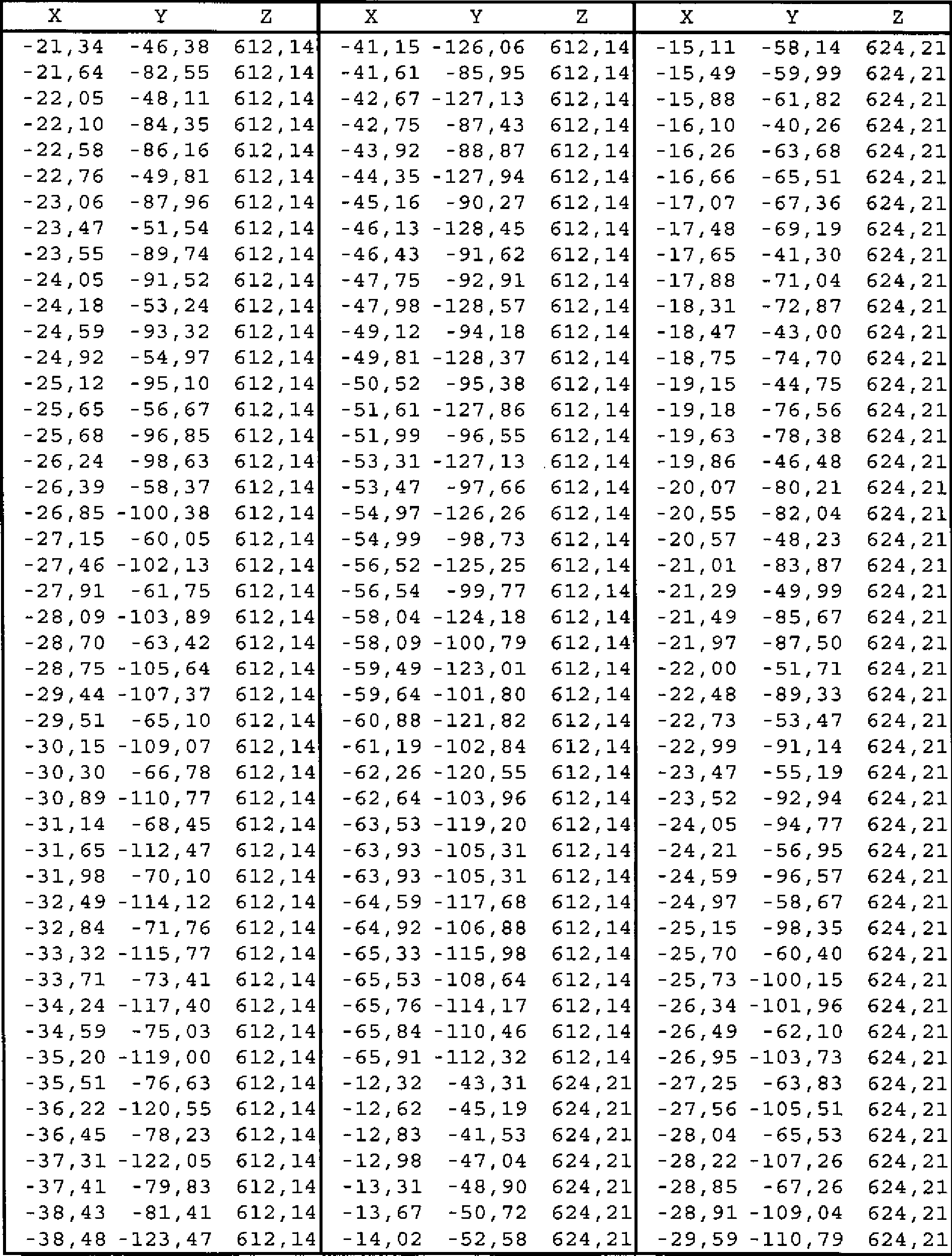
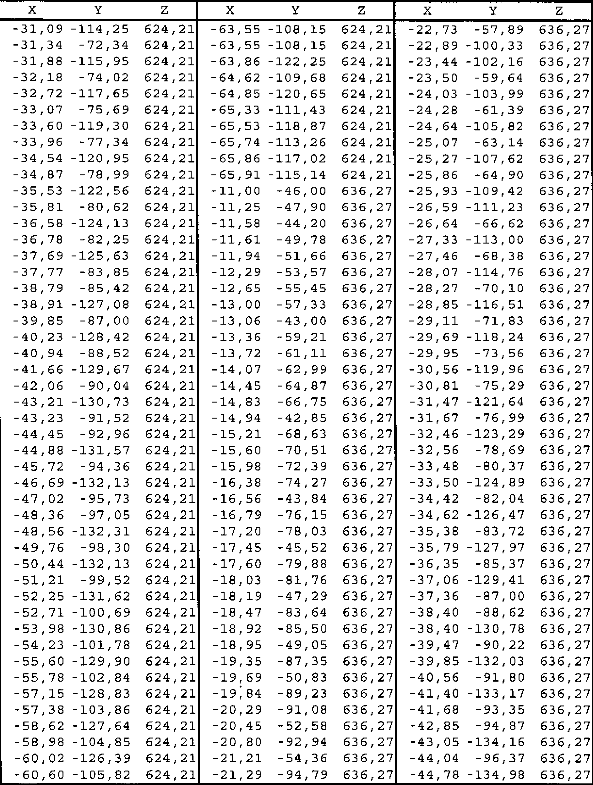
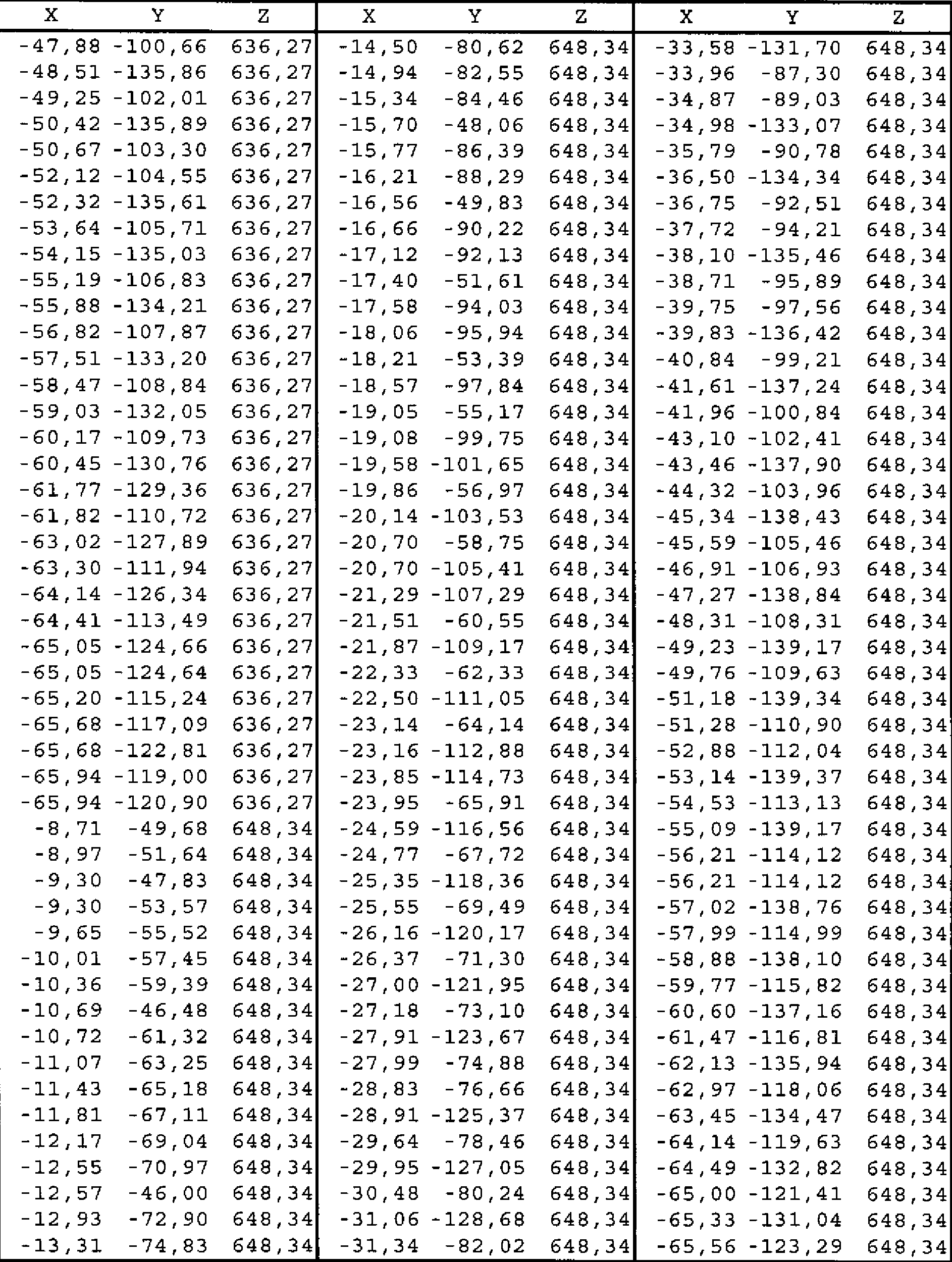
Leitschaufelblätter (32) der ersten Stufe verfügen über Innenkernprofile (38), die im Wesentlichen mit den Werten der in Tabelle I angegebenen kartesischen Koordinaten X, Y und Z übereinstimmen, wobei die X-, Y- und Z-Werte in Zoll angegeben sind. Die X- und Y-Werte sind Abstände, die, wenn sie durch glatte, fortlaufende Bögen verbunden werden, in jedem Abstand Z Innenkernprofilabschnitte definieren. Die Profilabschnitte an den Z-Abständen werden nahtlos miteinander verbunden, sodass sie ein vollständiges Innenkernprofil bilden. Die Abstände X, Y und Z können als eine Funktion der gleichen Konstante oder Zahl skaliert werden, um ein Innenkernprofil im vergrößerten oder verkleinerten Maßstab zu ergeben. Das durch die Abstände X, Y und Z angegebene nominale Innenkernprofil liegt in einer Hülle, die einen Abstand von ±0.030 Zoll in Richtungen senkrecht zu jeder Position auf der Fläche des Innenkernprofils aufweist.First stage vane blades (32) have inner core profiles (38) that substantially coincide with the values of the Cartesian coordinates X, Y, and Z given in Table I, where the X, Y, and Z values are in inches. The X and Y values are distances that, when joined by smooth, continuous arcs, define Z inner-core profile sections at each pitch. The profile sections at the Z-spacings are seamlessly connected together to form a complete inner core profile. The distances X, Y and Z can be scaled as a function of the same constant or number to give an inner-core profile on an enlarged or reduced scale. The nominal inner core profile indicated by the distances X, Y and Z lies in a shell having a spacing of ± 0.030 inches in directions perpendicular to any position on the surface of the inner core profile.

Description
Die vorliegende Erfindung betrifft ein Leitschaufelblatt einer Gasturbinenstufe und betrifft insbesondere das Innenkernprofil eines Leitschaufelblatts der ersten Stufe einer Turbine.The present invention relates to a gas turbine stage vane blade, and more particularly relates to the inner core profile of a first stage vane blade of a turbine.
Jede Stufe der Heißgasströmungsstrecke einer Gasturbine muss viele Systemanforderungen erfüllen, damit sie den Konstruktionszielen entspricht. Insbesondere die Düsenringsegmente der ersten Stufe des Turbinenabschnitts müssen die Betriebsanforderungen für diese Stufe und darüber hinaus die Anforderungen erfüllen, die an die Strömungseffizienz bei der Kühlung der Leitschaufelblätter, an die Lebensdauer und an die Wandstärkenverteilung gestellt werden.Each stage of the hot gas flow path of a gas turbine must meet many system requirements to meet the design goals. In particular, the first stage nozzle ring segments of the turbine section must meet the operating requirements for this stage and, moreover, the requirements placed on the flow efficiency of vane blade cooling, lifetime, and wall thickness distribution.
HINTERGRUND DER ERFINDUNGBACKGROUND OF THE INVENTION
Gemäß einer bevorzugten Ausführungsform der vorliegenden Erfindung wird für ein Schaufelblatt eines Gasturbinendüsenrings, vorzugsweise des Düsenrings der ersten Stufe, ein eindeutiges Innenkernprofil bereitgestellt, das die Leistung der Gasturbine verbessert. Es sollte nachvollziehbar sein, dass die äußere Form des Leitschaufelblatts dessen Interaktion mit den Turbinenschaufeln verbessert, die die Stufen der Turbine bilden. Gleichzeitig ist auch die Form des Innenkernprofils des Leitschaufelblatts von Bedeutung – zum einen aus strukturellen Gründen, zum anderen zur Optimierung der internen Kühlung durch die geeignete Wandstärke. Das Innenkernprofil des Leitschaufelblatts wird durch eine eindeutige Punktemenge definiert, die die erforderlichen Struktur- und Kühlungsanforderungen erfüllt, sodass eine bessere Turbinenleistung erzielt wird. Diese eindeutige Punktemenge definiert das nominale Innenkernprofil und ist durch die kartesischen Koordinaten X, Y und Z der nachfolgenden Tabelle I gekennzeichnet. Die in Tabelle I für 1200 Punkte enthaltenen Koordinatenwerte gelten für ein kaltes, d. h. bei Raumtemperatur gehaltenes Leitschaufelblatt, das entlang seiner Länge verschiedene Querschnitte aufweist. Die positiven X-, Y- und Z-Richtungen sind axial zum Auslassende der Turbine, tangential in Richtung der Motordrehung bei Blickrichtung nach hinten bzw. radial nach außen zur äußeren Plattform. Die X- und Y-Koordinaten sind als Längenmaß angegeben, d. h. in der Einheit Millimeter, und an jeder Z-Position nahtlos miteinander verbunden, sodass sie einen glatten, fortlaufenden Querschnitt des Innenkernprofils bilden. Die Z-Koordinaten sind entlang der Radien von der Turbinenachse als Längenmaß in der Einheit Millimeter angegeben. Jeder Abschnitt des Innenkernprofils in der XY-Ebene ist nahtlos mit den benachbarten Profilabschnitten in Z-Richtung verbunden, sodass unter Verwendung der in Tabelle I enthaltenen Koordinatenwerte das vollständige Innenkernprofil des Leitschaufelblatts gebildet wird.In accordance with a preferred embodiment of the present invention, for a gas turbine nozzle ring airfoil, preferably the first stage nozzle ring, a unique inner core profile is provided which improves the performance of the gas turbine engine. It should be appreciated that the outer shape of the vane blade improves its interaction with the turbine blades forming the stages of the turbine. At the same time, the shape of the inner core profile of the vane blade is important - on the one hand for structural reasons, on the other hand to optimize the internal cooling by the appropriate wall thickness. The inner core profile of the vane blade is defined by a unique set of points that meets the required structural and cooling requirements so that better turbine performance is achieved. This unique set of points defines the nominal inner core profile and is characterized by the Cartesian coordinates X, Y and Z of Table I below. The coordinate values contained in Table I for 1200 points apply to a cold, d. H. at room temperature held vane blade having along its length different cross-sections. The positive X, Y, and Z directions are axial to the outlet end of the turbine, tangential in the direction of motor rotation when viewed rearward, and radially outward toward the outer platform. The X and Y coordinates are given as a measure of length, d. H. in units of millimeters, and seamlessly connected at each Z-position so that they form a smooth, continuous cross section of the inner core profile. The Z coordinates are given along the radii of the turbine axis as a measure of length in millimeters. Each section of the inner-core profile in the XY plane is seamlessly connected to the adjacent Z-direction profile sections so that the complete inner-core profile of the vane blade is formed using the coordinate values contained in Table I.
Tabelle I enthält Koordinatenwerte für das vollständige Innenkernprofil des Schaufelblatts, dass die innere und die äußere Plattform sowie das dazwischen liegende Schaufelblatt durchdringt. Die physische Form des Innenkernprofils zwischen der inneren und der äußeren Plattform ist in Tabelle I durch die Schaufelblattbereiche angegeben, die durch Z-Grenzwerte zwischen 563,88 und 636,27 definiert sind.Table I contains coordinate values for the complete inner core profile of the airfoil that penetrates the inner and outer platforms and the airfoil therebetween. The physical shape of the inner core profile between the inner and outer platforms is indicated in Table I by the airfoil ranges defined by Z limits between 563.88 and 636.27.
Es sollte nachvollziehbar sein, dass sich beim Aufheizen der einzelnen Leitschaufelblätter während des Betriebs das Innenkernprofil verändert. Für Fertigungszwecke wird durch die X-, Y- und Z-Koordinaten daher das im Kalt- oder Raumtemperaturzustand befindliche Profil angegeben. Da ein gefertigtes Innenkernprofil eines Leitschaufelblatts sich von dem nominalen Profil unterscheiden kann, das durch die nachfolgende Tabelle definiert ist, wird durch einen Abstand von ±0,762 mm vom nominalen Profil in senkrechter Richtung zu jeder Flächenposition entlang dem nominalen Profil eine Profilhülle für dieses Innenkernprofil eines Leitschaufelblatts definiert. Das Profil hält dieser Variation stand, ohne dass es zu einer Beeinträchtigung der Mechanik, der Kühlung und der aerodynamischen Funktionen des Schaufelblatts kommt.It should be understood that when heating the individual vane blades during operation, the inner core profile changes. For manufacturing purposes, therefore, the X, Y and Z coordinates indicate the profile in cold or room temperature condition. Since a fabricated inner core profile of a vane blade may differ from the nominal profile defined by the following table, a profile shell for that inner core profile of a vane blade will be formed by a distance of ± 0.762 mm from the nominal profile in the direction perpendicular to each surface position along the nominal profile Are defined. The profile withstands this variation without compromising the mechanics, cooling and aerodynamic functions of the airfoil.
Gemäß einer bevorzugten Ausführungsform der vorliegenden Erfindung wird ein Turbinendüsenringsegment geschaffen, zu dem eine innere und eine äußere Plattform sowie ein zwischen den Plattformen angeordnetes Schaufelblatt gehören, wobei das Schaufelblatt ein nominales Innenkernprofil aufweist, von dem mindestens ein Bereich im Wesentlichen mit den Werten der kartesischen Koordinaten X, Y und Z übereinstimmt, die in Tabelle I zwischen den Z-Grenzwerten 563,88 und 636,27 angegeben sind, wobei es sich bei den zwischen den Grenzwerten liegenden Z-Werten um radiale Abstände von einer Turbinenachse zu Ebenen handelt, die senkrecht zu den Radien liegen, und wobei es sich bei den X- und Y-Werten um in Millimeter angegebene Abstände handelt, die, wenn sie durch glatte, fortlaufende Bögen verbunden werden, in jedem Abstand Z entlang des Schaufelblatts zwischen den Z-Grenzwerten Innenkernprofilabschnitte definieren, wobei die Profilabschnitte an den zwischen den Grenzwerten liegenden Z-Abständen nahtlos miteinander verbunden werden, so dass sie das Innenkernprofil des Schaufelblatts bilden. According to a preferred embodiment of the present invention, there is provided a turbine nozzle ring segment comprising an inner and an outer platform and an airfoil disposed between the platforms, the airfoil having a nominal inner core profile, at least a portion of which substantially matches the Cartesian coordinate values X, Y and Z given in Table I between the Z limits 563, 88 and 636, 27, where the Z values lying between the limits are radial distances from a turbine axis to planes that are perpendicular to the radii, and where the X and Y values are distances given in millimeters which, when joined by smooth continuous arcs, define inner core profile sections at each Z distance along the airfoil between the Z limits , wherein the profile sections at the lying between the limits ZA be joined seamlessly so that they form the inner core profile of the airfoil.
Gemäß einer weiteren Ausführungsform der vorliegenden Erfindung wird eine Turbine mit einer Vielzahl von in Umfangsrichtung um eine Achse der Turbine angeordneten Düsenringsegmenten bereitgestellt, zu denen jeweils eine innere und eine äußere Plattform sowie ein zwischen den Plattformen angeordnetes Schaufelblatt gehören, wobei das Schaufelblatt ein nominales Innenkernprofil aufweist, von dem mindestens ein Bereich im Wesentlichen mit den Werten der kartesischen Koordinaten X, Y und Z übereinstimmt, die in Tabelle I zwischen den Z-Grenzwerten 563,88 und 636,27 angegeben sind, wobei es sich bei den zwischen den Grenzwerten liegenden Z-Werten um radiale Abstände von einer Turbinenachse zu Ebenen handelt, die senkrecht zu den Radien liegen, und wobei es sich bei den X- und Y-Werten um in Millimeter angegebene Abstände handelt, die, wenn sie durch glatte, fortlaufende Bögen verbunden werden, in jedem Abstand Z entlang des Schaufelblatts zwischen den Z-Grenzwerten Innenkernprofilabschnitte definieren, wobei die Profilabschnitte an den zwischen den Grenzwerten liegenden Z-Abständen nahtlos miteinander verbunden werden, so dass sie das Innenkernprofil des Schaufelblatts bilden.According to another embodiment of the present invention, there is provided a turbine having a plurality of nozzle ring segments disposed circumferentially about an axis of the turbine, each including an inner and an outer platform and an airfoil disposed between the platforms, the airfoil having a nominal inner core profile of which at least one region substantially coincides with the values of the Cartesian coordinates X, Y and Z given in Table I between the Z limits 563, 88 and 636, 27, where the Z between the limits is Z. Values are radial distances from a turbine axis to planes which are perpendicular to the radii, and where the X and Y values are distances given in millimeters which, when joined by smooth continuous arcs, at any distance Z along the airfoil between the Z-limits inner core profile define sections, wherein the profile sections are seamlessly connected to each other at the Z-distances lying between the limit values, so that they form the inner core profile of the airfoil.
Gemäß einer weiteren Ausführungsform der vorliegenden Erfindung wird ein Turbinendüsenringsegment geschaffen, zu dem eine innere und eine äußere Plattform sowie ein zwischen den Plattformen angeordnetes Schaufelblatt gehören, wobei das Schaufelblatt ein nominales Innenkernprofil aufweist, das im Wesentlichen mit den Werten der in Tabelle I enthaltenen kartesischen Koordinaten X, Y und Z übereinstimmt, wobei es sich bei den Z-Werten um radiale Abstände von einer Turbinenachse zu Ebenen handelt, die senkrecht zu den Radien liegen, und wobei es sich bei den X- und Y-Werten um in Millimeter angegebene Abstände handelt, die, wenn sie durch glatte, fortlaufende Bögen verbunden werden, in jedem Abstand Z entlang des Schaufelblatts Innenkernprofilabschnitte definieren, wobei die Profilabschnitte an den Z-Abständen nahtlos miteinander verbunden werden, sodass sie das Innenkernprofil des Schaufelblatts bilden.According to another embodiment of the present invention, there is provided a turbine nozzle ring segment including an inner and an outer platform and an airfoil disposed between the platforms, the airfoil having a nominal inner core profile substantially equal to the values of the Cartesian coordinates contained in Table I. X, Y and Z coincide, where the Z values are radial distances from a turbine axis to planes perpendicular to the radii, and where the X and Y values are distances given in millimeters which, when joined by smooth, continuous sheets, define inner core profile sections at each Z distance along the airfoil, the profile sections being seamlessly joined together at the Z-spacings to form the inner core profile of the airfoil.
Gemäß einer weiteren Ausführungsform der vorliegenden Erfindung wird eine Turbine mit einer Vielzahl von in Umfangsrichtung um eine Achse der Turbine angeordneten Düsenringsegmenten bereitgestellt, zu denen jeweils eine innere und eine äußere Plattform sowie ein zwischen den Plattformen angeordnetes Schaufelblatt gehören, wobei jedes Schaufelblatt ein nominales Innenkernprofil aufweist, das im Wesentlichen mit den Werten der in Tabelle I enthaltenen kartesischen Koordinaten X, Y und Z übereinstimmt, wobei es sich bei den Z-Werten um radiale Abstände von einer Turbinenachse zu Ebenen handelt, die senkrecht zu den Radien liegen, und wobei es sich bei den X- und Y-Werten um in Millimeter angegebene Abstände handelt, die, wenn sie durch glatte, fortlaufende Bögen verbunden werden, in jedem Abstand Z entlang des Schaufelblatts Innenkernprofilabschnitte definieren, wobei die Profilabschnitte an den Z-Abständen nahtlos miteinander verbunden werden, so dass sie das Innenkernprofil des Schaufelblatts bilden.According to another embodiment of the present invention, there is provided a turbine having a plurality of nozzle ring segments disposed circumferentially about an axis of the turbine, each including an inner and an outer platform and an airfoil disposed between the platforms, each airfoil having a nominal inner core profile substantially coincident with the values of the Cartesian coordinates X, Y and Z shown in Table I, where the Z values are radial distances from a turbine axis to planes perpendicular to the radii, and wherein the X and Y values are distances given in millimeters which, when joined by smooth continuous arcs, define inner core profile sections at each Z distance along the airfoil, seamlessly connecting the profile sections at the Z distances, so that they have the inner core profile of the airfoil.
KURZBESCHREIBUNG DER ZEICHNUNGENBRIEF DESCRIPTION OF THE DRAWINGS
DETAILLIERTE BESCHREIBUNG DER ERFINDUNGDETAILED DESCRIPTION OF THE INVENTION
Im Folgenden wird auf die Zeichnungen Bezug genommen, wobei in
In
Das Innenkernprofil
Zur Definition des Innenkernprofils der einzelnen Leitschaufelblätter, die zwischen der inneren und der äußeren Plattform angeordnet sind, wird eine eindeutige Punktemenge im Raum bereitgestellt, die die Anforderungen der Stufe, die Kühlbereiche und die Wandstärke berücksichtigt und für die Fertigung geeignet ist. Diese eindeutige Punktemenge, die das Innenkernprofil
Durch das Definieren von X- und Y-Koordinatenwerten an ausgewählten Positionen in einer Z-Richtung senkrecht zur XY-Ebene kann das Innenkernprofil
Die Werte aus Tabelle I zur Definition des Innenkernprofils des Leitschaufelblatts werden generiert und mit zwei Dezimalstellen angezeigt. Bei den Innenkernprofilen des Leitschaufelblatts müssen gängige Fertigungstoleranzen und Beschichtungen berücksichtigt werden. Die in Tabelle I für das Profil angegebenen Werte gelten dementsprechend für ein nominales Innenkernprofil des Leitschaufelblatts. Daher sollte nachvollziehbar sein, dass übliche ±-Fertigungstoleranzen, d. h. ±-Werte, einschließlich aller Beschichtungsstärken den in der nachfolgenden Tabelle I angegebenen X- und Y-Werten hinzuzufügen sind. Dementsprechend definiert ein Abstand von ±0,762 mm in senkrechter Richtung zu jeder Flächenposition entlang des Innenkernprofils eine Innenkernprofilhülle für diese spezielle Konstruktion des Leitschaufelblatts und diese spezielle Turbine, d. h. einen Variationsbereich zwischen gemessenen Punktepositionen auf dem tatsächlichen Innenkernprofil bei nominaler Kälte oder Raumtemperatur und der Idealposition dieser Punkte, die in der nachfolgenden Tabelle I für die gleiche Temperatur angegeben ist. Das Innenkernprofil hält dieser Variation stand, ohne dass es zu einer Beeinträchtigung der Mechanik und der Kühlfunktionen kommt.The values in Table I for defining the inner core profile of the vane sheet are generated and displayed with two decimal places. In the inner core profiles of the vane blade common manufacturing tolerances and coatings must be considered. The values given for the profile in Table I accordingly apply to a nominal inner core profile of the vane blade. Therefore, it should be understandable that usual ± manufacturing tolerances, i. H. ± values, including all coating thicknesses, are to be added to the X and Y values given in Table I below. Accordingly, a distance of ± 0.762 mm in the direction perpendicular to each face position along the inner core profile defines an inner core profile sheath for this particular design of the vane blade and that particular turbine, i. H. a range of variation between measured point positions on the actual inner core profile at nominal cold or room temperature and the ideal position of these points, which are given in Table I below for the same temperature. The inner core profile withstands this variation without compromising the mechanics and cooling functions.
Die Werte in der nachfolgenden Tabelle I entsprechen den Werten der kartesischen Koordinaten X, Y und Z für das Innenkernprofil des Schaufelblatts, einschließlich dessen die innere und die äußere Plattform durchdringenden Bereichs. Die physische Konfiguration des Innenkernprofils zwischen der inneren und der äußeren Plattform ist in Tabelle 2 durch die Z-Grenzwerte zwischen 563,88 und 636,27 angegeben. Diese Z-Grenzwerte beginnen radial außerhalb der inneren Plattform bzw. radial innerhalb der äußeren Plattform und definieren die physische Form des Innenkernprofils zwischen diesen Grenzwerten.The values in Table I below correspond to the values of the Cartesian coordinates X, Y, and Z for the inner core profile of the airfoil, including the region penetrating the inner and outer platforms. The physical configuration of the inner core profile between the inner and outer platforms is given in Table 2 by the Z limits between 563.88 and 636.27. These Z limits begin radially outward of the inner platform and radially inside the outer platform, respectively, and define the physical shape of the inner core profile between these limits.
Die in der nachfolgenden Tabelle I angegebenen Koordinatenwerte ergeben die das Leitschaufelblatt einschließlich der inneren und der äußeren Plattform durchdringende Hülle des bevorzugten nominalen Innenkernprofils.The coordinate values given in Table I below provide the envelope of the preferred nominal inner core profile penetrating the vane blade including the inner and outer platforms.


Es sollte außerdem nachvollziehbar sein, dass das in der obigen Tabelle dargelegte Innenkernprofil des Leitschaufelblatte maßstäblich vergrößert oder verkleinert werden kann, damit es in anderen ähnlichen Turbinenkonstruktionen eingesetzt werden kann. Infolgedessen können die in Tabelle I angegebenen Koordinatenwerte so vergrößert oder verkleinert werden, dass das Innenkernprofil des Leitschaufelblatte unverändert bleibt. Eine skalierte Version der Koordinaten aus Tabelle I würde durch die X-, Y- und Z-Koordinatenwerte aus Tabelle I dargestellt, die mit einer konstanten Zahl multipliziert oder durch diese dividiert werden.It should also be understood that the inner core profile of the vane blade set forth in the above table can be scaled up or down to be used in other similar turbine designs. As a result, the coordinate values given in Table I can be increased or decreased such that the inner core profile of the vane blade remains unchanged. A scaled version of the coordinates in Table I would be represented by the X, Y, and Z coordinate values of Table I, which are multiplied by or divided by a constant number.
Während die Erfindung im Zusammenhang mit der Ausführungsform beschrieben wurde, die derzeit für die praktischste und bevorzugte Ausführungsform erachtet wird, versteht es sich, dass die Erfindung nicht auf die dargelegte Ausführungsform beschränkt ist, sondern im Gegenteil verschiedene Modifikationen und gleichwertige Anordnungen einschließt, die dem Geist und dem Geltungsbereich der beigefügten Ansprüche entsprechen.While the invention has been described in conjunction with the embodiment which presently considered to be the most practical and preferred embodiment, it is to be understood that the invention is not limited to the embodiment set forth but, on the contrary, includes various modifications and equivalent arrangements to the spirit and the scope of the appended claims.
BezugszeichenlisteLIST OF REFERENCE NUMBERS
- 1010
- HeißgasströmungsstreckeHot gas flow path
- 1212
- Gasturbinegas turbine
- 1414
- Leitschaufelnvanes
- 1616
- Turbinenschaufelnturbine blades
- 1717
- Turbinenrotorturbine rotor
- 1818
- Leitschaufelnvanes
- 2020
- Turbinenschaufelnturbine blades
- 2222
- Leitschaufelnvanes
- 2424
- Turbinenschaufelnturbine blades
- 2626
- Pfeil (Strömungsrichtung)Arrow (flow direction)
- 3030
- DüsenringsegmentNozzle ring segment
- 3232
- Schaufelblattairfoil
- 3434
- Innere PlattformInner platform
- 3636
- Äußere PlattformOuter platform
- 3838
- InnenkernprofilInterior apex
- 4040
- InnenwandflächeInner wall surface
- 4242
- InnenwandflächeInner wall surface
Claims (7)
Applications Claiming Priority (2)
| Application Number | Priority Date | Filing Date | Title |
|---|---|---|---|
| US10/853,240 US6994520B2 (en) | 2004-05-26 | 2004-05-26 | Internal core profile for a turbine nozzle airfoil |
| US10/853,240 | 2004-05-26 |
Publications (2)
| Publication Number | Publication Date |
|---|---|
| DE102005024160A1 DE102005024160A1 (en) | 2005-12-15 |
| DE102005024160B4 true DE102005024160B4 (en) | 2012-03-01 |
Family
ID=34711947
Family Applications (1)
| Application Number | Title | Priority Date | Filing Date |
|---|---|---|---|
| DE102005024160A Expired - Lifetime DE102005024160B4 (en) | 2004-05-26 | 2005-05-23 | Inner core profile for a vane blade of a turbine |
Country Status (6)
| Country | Link |
|---|---|
| US (1) | US6994520B2 (en) |
| JP (1) | JP2005337250A (en) |
| KR (1) | KR101143026B1 (en) |
| CN (1) | CN100564810C (en) |
| DE (1) | DE102005024160B4 (en) |
| GB (1) | GB2415231B (en) |
Families Citing this family (22)
| Publication number | Priority date | Publication date | Assignee | Title |
|---|---|---|---|---|
| US20060216144A1 (en) * | 2005-03-28 | 2006-09-28 | Sullivan Michael A | First and second stage turbine airfoil shapes |
| US7384243B2 (en) * | 2005-08-30 | 2008-06-10 | General Electric Company | Stator vane profile optimization |
| US7396211B2 (en) * | 2006-03-30 | 2008-07-08 | General Electric Company | Stator blade airfoil profile for a compressor |
| US7467926B2 (en) * | 2006-06-09 | 2008-12-23 | General Electric Company | Stator blade airfoil profile for a compressor |
| US7534094B2 (en) * | 2006-10-25 | 2009-05-19 | General Electric Company | Airfoil shape for a compressor |
| US7534093B2 (en) * | 2006-10-25 | 2009-05-19 | General Electric Company | Airfoil shape for a compressor |
| US7540715B2 (en) * | 2006-10-25 | 2009-06-02 | General Electric Company | Airfoil shape for a compressor |
| US7537435B2 (en) * | 2006-11-02 | 2009-05-26 | General Electric Company | Airfoil shape for a compressor |
| US7887295B2 (en) * | 2007-11-08 | 2011-02-15 | General Electric Company | Z-Notch shape for a turbine blade |
| US7976280B2 (en) * | 2007-11-28 | 2011-07-12 | General Electric Company | Turbine bucket shroud internal core profile |
| US8057169B2 (en) * | 2008-06-13 | 2011-11-15 | General Electric Company | Airfoil core shape for a turbine nozzle |
| US8113786B2 (en) * | 2008-09-12 | 2012-02-14 | General Electric Company | Stator vane profile optimization |
| US8573945B2 (en) * | 2009-11-13 | 2013-11-05 | Alstom Technology Ltd. | Compressor stator vane |
| US8568085B2 (en) * | 2010-07-19 | 2013-10-29 | Pratt & Whitney Canada Corp | High pressure turbine vane cooling hole distrubution |
| US8814526B2 (en) | 2011-11-28 | 2014-08-26 | General Electric Company | Turbine nozzle airfoil profile |
| US8740570B2 (en) | 2011-11-28 | 2014-06-03 | General Electric Company | Turbine bucket airfoil profile |
| US8827641B2 (en) | 2011-11-28 | 2014-09-09 | General Electric Company | Turbine nozzle airfoil profile |
| US8734116B2 (en) | 2011-11-28 | 2014-05-27 | General Electric Company | Turbine bucket airfoil profile |
| US9011101B2 (en) | 2011-11-28 | 2015-04-21 | General Electric Company | Turbine bucket airfoil profile |
| US9528379B2 (en) * | 2013-10-23 | 2016-12-27 | General Electric Company | Turbine bucket having serpentine core |
| US10443392B2 (en) * | 2016-07-13 | 2019-10-15 | Safran Aircraft Engines | Optimized aerodynamic profile for a turbine vane, in particular for a nozzle of the second stage of a turbine |
| US10443393B2 (en) * | 2016-07-13 | 2019-10-15 | Safran Aircraft Engines | Optimized aerodynamic profile for a turbine vane, in particular for a nozzle of the seventh stage of a turbine |
Citations (5)
| Publication number | Priority date | Publication date | Assignee | Title |
|---|---|---|---|---|
| DE3029082A1 (en) * | 1980-07-31 | 1982-02-18 | Kraftwerk Union AG, 4330 Mülheim | TURBO MACHINE SHOVEL |
| US5326221A (en) * | 1993-08-27 | 1994-07-05 | General Electric Company | Over-cambered stage design for steam turbines |
| US6022188A (en) * | 1996-10-28 | 2000-02-08 | Siemens Westinghouse Power Corporation | Airfoil |
| US6709239B2 (en) * | 2001-06-27 | 2004-03-23 | Bharat Heavy Electricals Ltd. | Three dimensional blade |
| EP1473440A2 (en) * | 2003-04-28 | 2004-11-03 | General Electric Company | Internal core profile for a turbine bucket |
Family Cites Families (9)
| Publication number | Priority date | Publication date | Assignee | Title |
|---|---|---|---|---|
| GB636860A (en) * | 1947-06-11 | 1950-05-10 | Westinghouse Electric Int Co | Improvements in or relating to stationary blading for turbines |
| US4214355A (en) * | 1977-12-21 | 1980-07-29 | General Electric Company | Method for repairing a turbomachinery blade tip |
| JPH01300002A (en) * | 1988-05-24 | 1989-12-04 | Toshiba Corp | Steam turbine nozzle device |
| US5980209A (en) * | 1997-06-27 | 1999-11-09 | General Electric Co. | Turbine blade with enhanced cooling and profile optimization |
| US6785961B1 (en) | 1999-11-12 | 2004-09-07 | General Electric Corporation | Turbine nozzle segment and method of repairing same |
| US6419445B1 (en) | 2000-04-11 | 2002-07-16 | General Electric Company | Apparatus for impingement cooling a side wall adjacent an undercut region of a turbine nozzle segment |
| US6464457B1 (en) | 2001-06-21 | 2002-10-15 | General Electric Company | Turbine leaf seal mounting with headless pins |
| US6722851B1 (en) * | 2003-03-12 | 2004-04-20 | General Electric Company | Internal core profile for a turbine bucket |
| US6893210B2 (en) * | 2003-10-15 | 2005-05-17 | General Electric Company | Internal core profile for the airfoil of a turbine bucket |
-
2004
- 2004-05-26 US US10/853,240 patent/US6994520B2/en not_active Expired - Lifetime
-
2005
- 2005-05-18 GB GB0510163A patent/GB2415231B/en not_active Expired - Lifetime
- 2005-05-23 DE DE102005024160A patent/DE102005024160B4/en not_active Expired - Lifetime
- 2005-05-25 JP JP2005151739A patent/JP2005337250A/en not_active Withdrawn
- 2005-05-25 KR KR1020050044170A patent/KR101143026B1/en not_active Expired - Lifetime
- 2005-05-26 CN CNB2005100759554A patent/CN100564810C/en not_active Expired - Lifetime
Patent Citations (5)
| Publication number | Priority date | Publication date | Assignee | Title |
|---|---|---|---|---|
| DE3029082A1 (en) * | 1980-07-31 | 1982-02-18 | Kraftwerk Union AG, 4330 Mülheim | TURBO MACHINE SHOVEL |
| US5326221A (en) * | 1993-08-27 | 1994-07-05 | General Electric Company | Over-cambered stage design for steam turbines |
| US6022188A (en) * | 1996-10-28 | 2000-02-08 | Siemens Westinghouse Power Corporation | Airfoil |
| US6709239B2 (en) * | 2001-06-27 | 2004-03-23 | Bharat Heavy Electricals Ltd. | Three dimensional blade |
| EP1473440A2 (en) * | 2003-04-28 | 2004-11-03 | General Electric Company | Internal core profile for a turbine bucket |
Also Published As
| Publication number | Publication date |
|---|---|
| CN1702302A (en) | 2005-11-30 |
| KR101143026B1 (en) | 2012-05-08 |
| US20050265829A1 (en) | 2005-12-01 |
| GB2415231B (en) | 2008-08-06 |
| CN100564810C (en) | 2009-12-02 |
| GB0510163D0 (en) | 2005-06-22 |
| GB2415231A (en) | 2005-12-21 |
| US6994520B2 (en) | 2006-02-07 |
| KR20060048096A (en) | 2006-05-18 |
| DE102005024160A1 (en) | 2005-12-15 |
| JP2005337250A (en) | 2005-12-08 |
Similar Documents
| Publication | Publication Date | Title |
|---|---|---|
| DE102005024160B4 (en) | Inner core profile for a vane blade of a turbine | |
| CH697806A2 (en) | Turbine blade shroud edge profile. | |
| DE102007051413A1 (en) | Guiding device for turbine i.e. gas turbine, has turbine blade including nominal profile based on Cartesian coordinate values X, Y and Z, where profiles flowing in z-distances are connected with one another to form turbine blade shape | |
| DE102008002975A1 (en) | Blade blade shape for a turbine blade and turbine with this | |
| DE102014114989B4 (en) | Turbine blade with sepentine core, turbine runner section with such a turbine blade and turbine | |
| DE102008002976A1 (en) | Airfoil shape for a turbine blade and turbine provided therewith | |
| EP2478186B1 (en) | Rotor of a turbomachine | |
| DE102007051417A1 (en) | Gas turbine engine arrangement, particularly turbine blade for rotating blade, has uncoated profile that is corresponding to cartesian coordinate values of X, Y and Z according to description in certain table | |
| DE112020000789B4 (en) | HIGH TEMPERATURE COMPONENT AND METHOD FOR PRODUCING THE HIGH TEMPERATURE COMPONENT | |
| DE102008037583A1 (en) | Shank profile form for a turbine blade and turbine with this | |
| DE102014119423B4 (en) | Internal cooling circuits in turbine blades | |
| DE102009003794A1 (en) | Airfoil shape for a turbine blade | |
| DE112022000304T5 (en) | TURBINE BLADE TIP COVER SURFACE PROFILES | |
| DE102014119418B4 (en) | Structural arrangements and cooling circuits in turbine blades | |
| CH709089A2 (en) | The turbine blade having a chamber for receiving a cooling medium flow. | |
| DE112023003353T5 (en) | AIR GUIDE VANES OF A COMPRESSOR STATOR GUIDE VANE | |
| DE102023116510A1 (en) | TURBINE NOZZLE ASSEMBLY WITH STRESS RELIEF STRUCTURE FOR MOUNTING RAILS | |
| DE102023116511A1 (en) | TURBINE NOZZLE ASSEMBLY WITH STRESS RELIEF STRUCTURE FOR MOUNTING RAILS | |
| EP2410131A2 (en) | Rotor of a turbomachine | |
| DE102017221684A1 (en) | Turbomachinery flow channel | |
| DE202013004444U1 (en) | Blade for a compressor and compressor with such a blade | |
| DE102012002465A1 (en) | Gas turbine combustor with unsymmetrical fuel nozzles | |
| DE112023002831T5 (en) | AIR GUIDE VANES OF A COMPRESSOR STATOR GUIDE VANE | |
| EP3623576B1 (en) | Gas turbine rotor blade | |
| DE112023001877T5 (en) | ROTOR BLADE AND THE GAS TURBINE EQUIPPED WITH IT |
Legal Events
| Date | Code | Title | Description |
|---|---|---|---|
| 8110 | Request for examination paragraph 44 | ||
| R016 | Response to examination communication | ||
| R016 | Response to examination communication | ||
| R018 | Grant decision by examination section/examining division | ||
| R020 | Patent grant now final |
Effective date: 20120602 |
|
| R081 | Change of applicant/patentee |
Owner name: GENERAL ELECTRIC TECHNOLOGY GMBH, CH Free format text: FORMER OWNER: GENERAL ELECTRIC CO., SCHENECTADY, N.Y., US |
|
| R082 | Change of representative | ||
| R071 | Expiry of right |