DE102005021615B4 - Housing member with connector part - Google Patents
Housing member with connector part Download PDFInfo
- Publication number
- DE102005021615B4 DE102005021615B4 DE102005021615A DE102005021615A DE102005021615B4 DE 102005021615 B4 DE102005021615 B4 DE 102005021615B4 DE 102005021615 A DE102005021615 A DE 102005021615A DE 102005021615 A DE102005021615 A DE 102005021615A DE 102005021615 B4 DE102005021615 B4 DE 102005021615B4
- Authority
- DE
- Germany
- Prior art keywords
- seal member
- chamber
- connector
- housing
- connection terminals
- Prior art date
- Legal status (The legal status is an assumption and is not a legal conclusion. Google has not performed a legal analysis and makes no representation as to the accuracy of the status listed.)
- Expired - Lifetime
Links
Classifications
-
- H—ELECTRICITY
- H02—GENERATION; CONVERSION OR DISTRIBUTION OF ELECTRIC POWER
- H02G—INSTALLATION OF ELECTRIC CABLES OR LINES, OR OF COMBINED OPTICAL AND ELECTRIC CABLES OR LINES
- H02G3/00—Installations of electric cables or lines or protective tubing therefor in or on buildings, equivalent structures or vehicles
- H02G3/02—Details
- H02G3/08—Distribution boxes; Connection or junction boxes
- H02G3/088—Dustproof, splashproof, drip-proof, waterproof, or flameproof casings or inlets
-
- H—ELECTRICITY
- H01—ELECTRIC ELEMENTS
- H01R—ELECTRICALLY-CONDUCTIVE CONNECTIONS; STRUCTURAL ASSOCIATIONS OF A PLURALITY OF MUTUALLY-INSULATED ELECTRICAL CONNECTING ELEMENTS; COUPLING DEVICES; CURRENT COLLECTORS
- H01R13/00—Details of coupling devices of the kinds covered by groups H01R12/70 or H01R24/00 - H01R33/00
- H01R13/46—Bases; Cases
- H01R13/52—Dustproof, splashproof, drip-proof, waterproof, or flameproof cases
- H01R13/5219—Sealing means between coupling parts, e.g. interfacial seal
-
- H—ELECTRICITY
- H01—ELECTRIC ELEMENTS
- H01R—ELECTRICALLY-CONDUCTIVE CONNECTIONS; STRUCTURAL ASSOCIATIONS OF A PLURALITY OF MUTUALLY-INSULATED ELECTRICAL CONNECTING ELEMENTS; COUPLING DEVICES; CURRENT COLLECTORS
- H01R13/00—Details of coupling devices of the kinds covered by groups H01R12/70 or H01R24/00 - H01R33/00
- H01R13/46—Bases; Cases
- H01R13/52—Dustproof, splashproof, drip-proof, waterproof, or flameproof cases
- H01R13/521—Sealing between contact members and housing, e.g. sealing insert
Landscapes
- Engineering & Computer Science (AREA)
- Architecture (AREA)
- Civil Engineering (AREA)
- Structural Engineering (AREA)
- Connector Housings Or Holding Contact Members (AREA)
- Camera Bodies And Camera Details Or Accessories (AREA)
- Studio Devices (AREA)
- Casings For Electric Apparatus (AREA)
Abstract
Gehäuseglied,
mit:
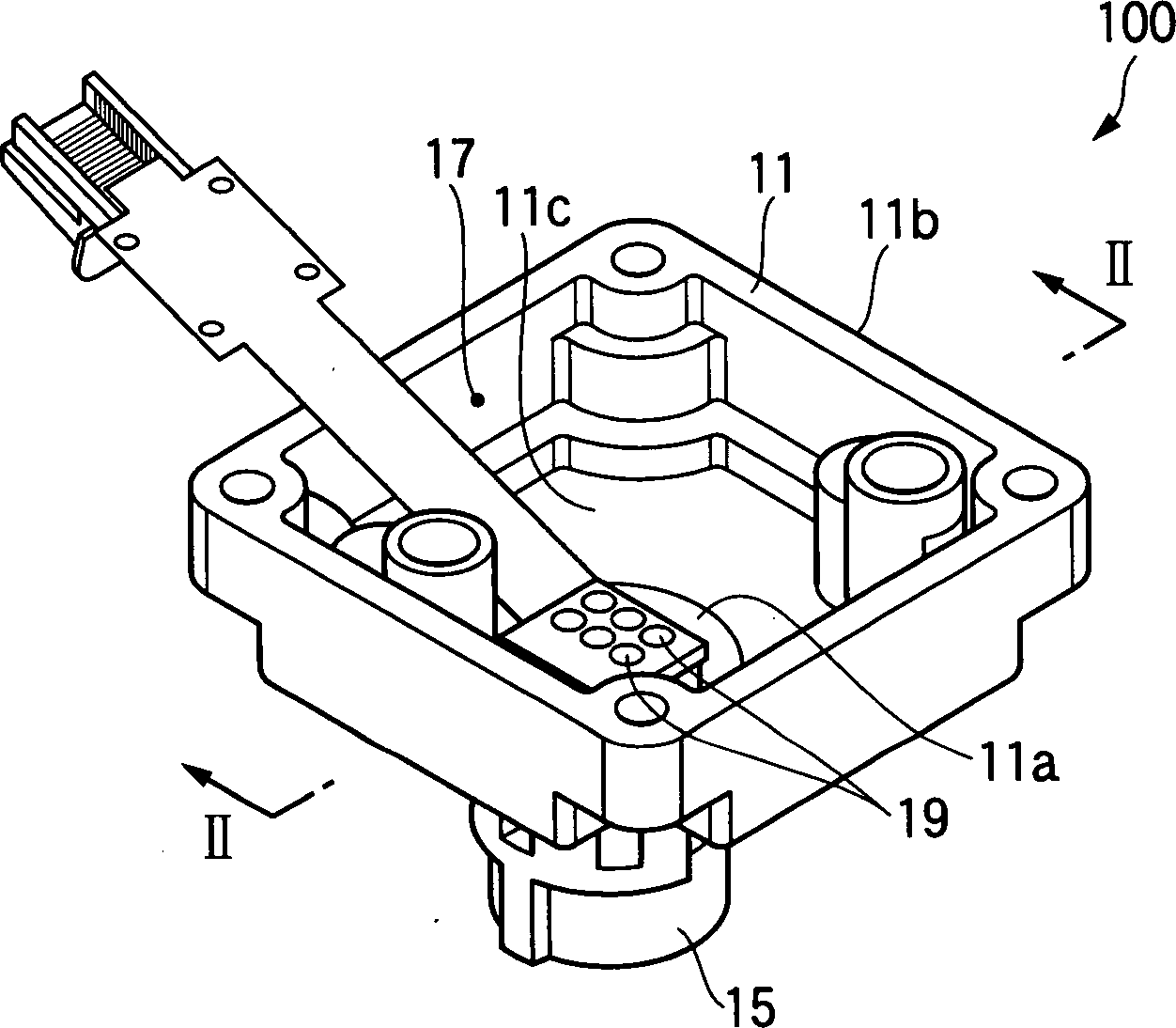
einem Gehäuseteil
(12), in dem eine Elektroeinrichtungskammer (17) zum Aufnehmen einer
elektrischen Einrichtung ausgebildet ist,
einem Steckverbindungsteil
(18), der einstückig
mit dem Gehäuseteil
(12) ausgebildet ist und umfasst:
eine Dichtungsgliedkammer
(21),
eine Trennwand (11a) zwischen der Dichtungsgliedkammer
(21) und der Elektroeinrichtungskammer (17), um die Dichtungsgliedkammer
(21) und die Elektroeinrichtungskammer (17) voneinander zu trennen,
und
Verbindungsanschlüsse
(19), die an der Trennwand (11a) befestigt sind, sich durch die
Trennwand (11a) erstrecken und entsprechende elektrische Kontaktteile
(19a) aufweisen, die in die Dichtungsgliedkammer (21) vorstehen,
einem
Dichtungsglied (13), das in der Dichtungsgliedkammer (21) derart
montiert ist, dass sich die elektrischen Kontaktteile (19a) der
Verbindungsanschlüsse
(19) durch das Dichtungsglied (13) erstrecken, und
einer Dichtungsgliedhalterung
(15), die an einer Außenumfangsfläche des
Steckverbindungsteils (18) befestigt ist,
wobei die Länge jedes
Verbindungsanschlusses (19), die von der Trennwand (11a) zu der
Dichtungsgliedkammer (21) vorsteht, größer ist als die...Housing member, with:
a housing part (12) in which an electrical equipment chamber (17) for receiving an electrical device is formed,
a plug connection part (18) which is formed integrally with the housing part (12) and comprises:
a seal member chamber (21),
a partition wall (11a) between the seal member chamber (21) and the electrical equipment chamber (17) for separating the seal member chamber (21) and the electrical equipment chamber (17), and
Connection terminals (19) fixed to the partition wall (11a), extending through the partition wall (11a), and having corresponding electrical contact parts (19a) protruding into the seal member chamber (21),
a seal member (13) mounted in the seal member chamber (21) so that the electrical contact parts (19a) of the connection terminals (19) extend through the seal member (13), and
a seal member holder (15) fixed to an outer peripheral surface of the connector part (18),
wherein the length of each connection port (19) projecting from the partition wall (11a) to the seal member chamber (21) is larger than the length of each connection port (19).
Description
Die vorliegende Erfindung betrifft ein Gehäuseglied mit einem Steckverbindungsteil und insbesondere ein Gehäuseglied zum Aufnehmen einer elektrischen Einrichtung in einem gedichteten Zustand.The The present invention relates to a housing member having a connector part and in particular a housing member for receiving an electrical device in a sealed Status.
Die
Zum Beispiel muss eine Fahrzeug-CCD-Kameraeinheit (als elektrische Einrichtung) einen hohen Grad von Luftdichtigkeit (d. h. eine hohe Dichtungsfähigkeit) aufweisen, um die Fahrzeug-CCD-Kamera vor Fremdstoffen wie Staub, Schmutz und Wasser zu schützen.To the Example must be a vehicle CCD camera unit (as an electrical device) a high degree of airtightness (i.e., a high sealing ability) to prevent the vehicle CCD camera from contaminants such as dust, Protect dirt and water.
Die meisten in Fahrzeugbatterien weisen eine Nennausgangsspannung von 12 V auf, wobei es jedoch auch Fahrzeugbatterien mit ein Nennausgangsspannungen von 24 V, 36 V usw. gibt.The Most in vehicle batteries have a nominal output voltage of 12V, but there are also vehicle batteries with a nominal output voltages of 24 V, 36 V etc. are.
Weiterhin ist die interne Betriebsspannung der Fahrzeug-CCD-Kameraeinheit niedriger (zum Beispiel um 3 V oder mehr) als die Ausgangsspannung der Fahrzeugbatterie, sodass ein Gleichstrom/Gleichstrom-Wandler in der Fahrzeug-CCD-Kameraeinheit vorgesehen ist, um die von der Fahrzeugbatterie zugeführte Stromversorgung zu einer internen Betriebsspannung für die Fahrzeug-CCD-Kameraeinheit zu wandeln.Farther is the internal operating voltage of the vehicle CCD camera unit lower (for example by 3 V or more) than the output voltage the vehicle battery, so a DC / DC converter is provided in the vehicle CCD camera unit to those of the Vehicle battery supplied Power supply to an internal operating voltage for the vehicle CCD camera unit convert.
Aufgrund eines Verlusts bei der Spannungswandlung durch den Gleichstrom/Gleichstrom-Wandler der Fahrzeug-CCD-Kameraeinheit wird Wärme erzeugt, wodurch die Temperatur eines Gehäuseglieds, in dem die Fahrzeug-CCD-Kamera dichtend aufgenommen ist, stark erhöht wird. Um die Wärme besser abstrahlen zu können, wird bevorzugt ein Gehäuseglied aus einem Metall wie etwa Aluminium verwendet.by virtue of a loss in voltage conversion by the DC / DC converter the vehicle CCD camera unit becomes Generates heat, whereby the temperature of a housing member, in which the vehicle CCD camera is sealingly received, is greatly increased. To the heat to radiate better, is preferably a housing member made of a metal such as aluminum.
Es
ist eine Technik bekannt, in der eine Fahrzeug-CCD-Kameraeinheit mit
einem Steckverbindungsteil in einem Gehäuseglied aus zum Beispiel Aluminium
montiert wird, wobei ein Zwischenraum zwischen dem Steckverbindungsteil
der Fahrzeug-CCD-Kameraeinheit und dem Gehäuseglied durch ein Dichtungsglied
(einen Gummipfropfen) gedichtet wird, um das Gehäuseglied zu dichten (siehe zum
Beispiel die ungeprüfte
In den letzten Jahren wurde die Wärmeerzeugung in einem Gleichstrom/Gleichstrom-Wandler durch eine verbesserte Spannungswandlungseffizienz stark reduziert, sodass es nicht mehr erforderlich ist, ein Gehäuseglied aus Metall zum Aufnehmen einer Fahrzeug-CCD-Kameraeinheit mit einem derartigen Gleichstrom/Gleichstrom-Wandler in einem gedichteten Zustand zu verwenden.In The last few years have been heat generation in a DC / DC converter by an improved Voltage conversion efficiency is greatly reduced, so it no longer works is required, a housing member of metal for receiving a vehicle CCD camera unit with a Such DC / DC converter in a sealed Condition to use.
Deshalb wird verstärkt eine Technik verwendet, bei der ein Gehäuseglied aus Kunstharz zum Aufnehmen einer Fahrzeug-CCD-Kameraeinheit verwendet wird, um einen leichteren Aufbau und eine Kostenreduktion zu erzielen. Hinsichtlich der Verwendung von derartigen Gehäusegliedern aus Kunstharz wurde eine Technik untersucht, bei der eine Steckverbindung mit Anschlüssen (für die elektrische Verbindung zu der CCD-Kameraeinheit in dem Gehäuseglied) einstückig mit dem Gehäuseglied gegossen wird. Insbesondere wurde eine Technik zum Ausbilden des Gehäuseglieds einschließlich eines Steckverbindungsteils mit Verbindungsanschlüssen durch ein Insert-Molding untersucht.Therefore is amplified used a technique in which a housing member made of synthetic resin for picking up a vehicle CCD camera unit is used to facilitate construction and cost reduction to achieve. Regarding the use of such housing members made of synthetic resin, a technique was investigated in which a connector with connections (for the electrical connection to the CCD camera unit in the housing member) one piece with the housing member is poured. In particular, a technique for forming the housing member including one Plug connection part with connection terminals by insert molding examined.
Bei einem Insert-Molding entwickeln sich jedoch feine Zwischenräume zwischen den Verbindungsanschlüssen und dem gegossenen Kunstharz, sodass ein Dichtungsglied in dem Verbindungsteil (mit den Verbindungsanschlüssen) in engem Kontakt zu den Verbindungsanschlüssen gehalten wird. Um Einwirkungen von Fremdstoffen (wie etwa Schmutz, Staub und Wasser) auf die Fahrzeug-CCD-Kameraeinheit zu verhindern, ist ein Gehäuseglied zum Aufnehmen der Fahrzeug-CCD-Kameraeinheit in einem gedichteten Zustand erforderlich, der eine derart hohe Dichtungsfähigkeit aufweist, dass kein Lecken auftritt, wenn das Gehäuseglied einem Druck von zum Beispiel 400 kPa ausgesetzt wird.at However, an insert molding develops fine gaps between the connection terminals and the molded resin, so that a sealing member in the connecting part (with the connection terminals) is kept in close contact with the connection terminals. For actions of foreign matter (such as dirt, dust and water) on the vehicle CCD camera unit to prevent is a housing member for picking up the vehicle CCD camera unit in a sealed one Condition required, which has such a high sealing ability indicates that no leakage occurs when the housing member is exposed to a pressure of, for example, 400 kPa.
In
einem Beispiel für
eine Steckverbindung mit einem Dichtungsglied erstrecken sich die
Verbindungsanschlüsse
durch das Dichtungsglied und weisen einen engen Kontakt zu demselben
auf (siehe zum Beispiel die ungeprüfte
Die Steckverbindungskammer der Steckverbindung weist eine vorbestimmte Länge (d. h. Tiefe) auf, um in eine komplementäre Steckverbindung eingeführt zu werden, wobei diese komplementäre Steckverbindung geführt wird, damit die männlichen Verbindungsanschlüsse, die sich in engem Kontakt durch das Dichtungsglied erstrecken, positiv mit weiblichen Verbindungsanschlüssen in der komplementären Steckverbindung verbunden werden können.The Connector chamber of the connector has a predetermined Length (i. H. Depth) to be inserted into a complementary connector, being this complementary connector guided is for the male connection connections, the extending in close contact through the sealing member, positive with female connection terminals in the complementary Plug connection can be connected.
Wenn
also die komplementäre
Steckverbindung mit der Steckverbindungskammer der Steckverbindung
gemäß der ungeprüften
Wenn bei dem Steckverbindungsaufbau der oben genannten Referenz das Dichtungsglied in der Steckverbindungskammer montiert wird, wird das Dichtungsglied durch das offene Ende in die Steckverbindungskammer eingeführt, wobei dann die Verbindungsanschlüsse jeweils durch Anschlussdurchgangslöcher in das Dichtungsglied eingeführt werden. Dieser Vorgang ist jedoch schwierig und zeitaufwändig, wodurch die Effizienz der Montageoperation herabgesetzt wird.If in the connector assembly of the above reference, the seal member is mounted in the connector chamber, the seal member inserted through the open end in the connector chamber, wherein then the connection connections respectively through terminal through holes in the seal member introduced become. This process is difficult and time consuming, however the efficiency of the assembly operation is reduced.
Bei einem Dichtungsglied mit einer hohen Dichtungsleistung werden ringförmige Lippen für den Kontakt mit der Innenumfangswand der Steckverbindungskammer auf der Außenumfangsfläche des Dichtungsglieds ausgebildet und stehen von derselben vor, wobei das Dichtungsglied unter Quetschung der ringförmigen Lippen in die Steckverbindungskammer eingeführt (pressgepasst) wird. Auf diese Weise wird die Position des Dichtungsglieds in der Steckverbindungskammer durch die Außenumfangsfläche (d. h. durch die ringförmigen Lippen) des Dichtungsglieds bestimmt, wobei die Position des Dichtungsglieds in der Steckverbindungskammer nicht in Übereinstimmung mit den Positionen der Verbindungsanschlüsse angepasst werden kann. Deshalb ist es schwierig, das Dichtungsglied zu montieren und insbesondere die Verbindungsanschlüsse durch die entsprechenden Anschlussdurchgangslöcher in dem Dichtungsglied zu führen. Außerdem besteht die Möglichkeit, dass die Verbindungsanschlüsse beim Einpressen mit ihren entfernten Enden das Dichtungsglied beschädigen, wodurch die Dichtungsleistung beeinträchtigt wird.at A sealing member having a high sealing performance becomes annular lips for the contact with the inner peripheral wall of the connector chamber on the outer peripheral surface of the seal member formed and protrude from the same, wherein the sealing member under bruising of the annular Lips inserted into the connector chamber (press fit) is. On this way, the position of the sealing member in the connector chamber through the outer peripheral surface (i. H. through the annular Lips) of the sealing member determined, the position of the sealing member in the connector chamber not in accordance with the positions the connection terminals can be adjusted. Therefore, it is difficult, the seal member to assemble and in particular the connection connections through the corresponding terminal through holes in the sealing member respectively. Furthermore it is possible, that the connection connections when pressed with their distal ends damage the seal member, causing the sealing performance is impaired becomes.
Die vorliegende Erfindung nimmt auf die oben beschriebenen Umstände Bezug, wobei es eine Aufgabe der Erfindung ist, ein Gehäuseglied mit einem Aufbau zum Verbessern der Effizienz einer Operation zum Montieren eines Dichtungsglieds in einer Dichtungsgliedkammer anzugeben.The The present invention relates to the circumstances described above. It is an object of the invention to provide a housing member with a structure for Improve the efficiency of an operation to mount a seal member in a seal member chamber.
Die oben genannte Aufgabe wird durch ein Gehäuseglied der vorliegenden Erfindung mit den in den folgenden Absätzen genannten Merkmalen gelöst.The The above object is achieved by a housing member of the present invention with the following paragraphs solved mentioned features.
Ein
Gehäuseglied
umfasst:
einen Gehäuseteil,
in dem eine Elektroeinrichtungskammer zum Aufnehmen einer elektrischen
Einrichtung ausgebildet ist,
einen Steckverbindungsteil, der
einstückig
mit dem Gehäuseteil
ausgebildet ist und eine Dichtungsgliedkammer, eine Trennwand zwischen
der Dichtungsgliedkammer und der Elektroeinrichtungskammer, um die
Dichtungsgliedkammer und die Elektroeinrichtungskammer voneinander
zu trennen, und Verbindungsanschlüsse umfasst, wobei die Verbindungsanschlüsse an der
Trennwand befestigt sind, sich durch die Trennwand erstrecken und
entsprechende elektrische Kontaktteile aufweisen, die in die Dichtungsgliedkammer
vorstehen,
ein Dichtungsglied, das in der Dichtungsgliedkammer derart
montiert ist, dass sich die elektrischen Kontaktteile der Verbindungsanschlüsse durch
das Dichtungsglied erstrecken, und
eine Dichtungsgliedhalterung,
die an einer Außenumfangsfläche des
Steckverbindungsteils befestigt ist,
wobei die Länge jedes
Verbindungsanschlusses, die von der Trennwand in die Dichtungsgliedkammer vorsteht
und den elektrischen Kontaktteil umfasst, größer ist als die Höhe einer
Außenumfangswand des
Steckverbindungsteils, die von der Trennwand vorsteht und die elektrischen
Kontaktteile der Verbindungsanschlüsse umgibt, um die Dichtungsgliedkammer
zu bilden, sodass wenigstens entfernte Endteile der elektrischen
Kontaktteile der Verbindungsanschlüsse von dem Steckverbindungsteil
nach außen
in einer Richtung vorstehen, in welcher der Steckverbindungsteil
mit einer komplementären Steckverbindung
verbunden wird.A housing member comprises:
a housing part in which an electrical equipment chamber for receiving an electrical device is formed,
a connector part integrally formed with the housing part, and a seal member chamber, a partition wall between the seal member chamber and the electrical equipment chamber to separate the seal member chamber and the electrical equipment chamber, and connection terminals, the connection terminals being fixed to the partition wall, through the partition wall extend and have corresponding electrical contact parts which protrude into the seal member chamber,
a seal member mounted in the seal member chamber such that the electrical contact portions of the connection terminals extend through the seal member, and
a seal member holder fixed to an outer peripheral surface of the connector part,
wherein the length of each connection terminal projecting from the partition wall into the seal member chamber and including the electrical contact part is greater than the height of an outer peripheral wall of the connector part projecting from the partition wall and surrounding the electrical contact parts of the connection terminals to form the seal member chamber at least remote end portions of the electrical contact portions of the connection terminals project outwardly from the connector portion in a direction in which the connector portion is connected to a complementary connector.
Bei dem oben beschriebenen Gehäuseglied ist die elektrische Einrichtung eine CCD-Kameraeinheit, die in einem gedichteten Zustand in der Elektroeinrichtungskammer aufgenommen wird.at the housing member described above the electrical device a CCD camera unit, which in a sealed condition recorded in the electrical equipment chamber becomes.
Bei dem Gehäuseglied mit dem oben beschriebenen Aufbau stehen wenigstens die entfernten Endteile der elektrischen Kontaktteile der Verbindungsanschlüsse von der Dichtungsgliedkammer nach außen vor. Wenn also das Dichtungsglied in der Dichtungsgliedkammer montiert wird, werden die entfernten Endteile der elektrischen Kontaktteile der Verbindungsanschlüsse jeweils in Anschlussdurchgangslöcher in dem Dichtungsglied eingeführt, um das Dichtungsglied zu positionieren, wobei danach das Dichtungsglied in die Dichtungsgliedkammer geschoben werden kann, um dasselbe dort zu montieren. Bei dem Gehäuseglied mit dem oben beschriebenen Aufbau kann also die Positionierung des Dichtungsglieds relativ zu dem Verbindungsteil einfach durchgeführt werden, wobei außerdem eine Beschädigung des Dichtungsglieds durch die entfernten Enden der Verbindungsanschlüsse bei der Montage des Dichtungsglieds verhindert wird. Bei dem Gehäuseglied mit dem oben beschriebenen Aufbau kann also die Effizienz der Operation zum Montieren des Dichtungsglieds verbessert werden. Nachdem das Dichtungsglied in der Dichtungsgliedkammer montiert wurde, wird die Dichtungsgliedhalterung in dem Steckverbindungsteil montiert. Wenn also der Steckverbindungsteil und die komplementäre Steckverbindung miteinander verbunden werden, wird eine Innenumfangsfläche des Teils der Dichtungsgliedhalterung an einem offenen Ende der Dichtungsgliedkammer mit der komplementären Steckverbindung verbunden, wobei die komplementäre Steckverbindung durch die Innenumfangsfläche der Dichtungsgliedhalterung geführt wird, wodurch die zwei Steckverbindungen relativ zueinander positioniert werden, wobei danach die Verbindungsanschlüsse der komplementären Steckverbindung jeweils mit den Verbindungsanschlüssen in dem Steckverbindungsteil verbunden werden.In the case of the housing member having the structure described above, at least the distal end parts of the electrical contact parts of the connection terminals project outwardly from the seal member chamber. Thus, when the seal member is mounted in the seal member chamber, the distal end portions of the electrical contact portions of the connection terminals are respectively inserted into terminal through holes in the seal member to position the seal member, and thereafter the seal member can be pushed into the seal member chamber to mount the same there. In the housing member having the structure described above, so the positioning of you In addition, damage to the sealing member is prevented by the distal ends of the connecting terminals during assembly of the sealing member. Thus, in the case of the housing member having the structure described above, the efficiency of the operation for mounting the seal member can be improved. After the seal member is mounted in the seal member chamber, the seal member holder is mounted in the connector part. Thus, when the male and female connectors are connected together, an inner peripheral surface of the portion of the seal member holder is connected to the mating connector at an open end of the seal member chamber, the complementary male connector being passed through the inner peripheral surface of the seal member holder, thereby positioning the two connectors relative to each other After that, the connection terminals of the complementary connector are respectively connected to the connection terminals in the connector part.
Das oben beschriebene Gehäuseglied ist dafür geeignet, für die Aufnahme einer CCD-Kameraeinheit wie oben beschrieben verwendet zu werden.The above described housing member is for that suitable for used the recording of a CCD camera unit as described above to become.
Bei dem Gehäuseglied der vorliegenden Erfindung kann die Effizienz der Operation zum Montieren des Dichtungsglieds in der Dichtungsgliedkammer des Steckverbindungsteils effektiv erhöht werden, wobei außerdem verhindert wird, dass das Dichtungsglied bei der Montage des Dichtungsglieds durch die entfernten Enden der Verbindungsanschlüsse beschädigt wird.at the housing member According to the present invention, the efficiency of the operation for Mounting the seal member in the seal member chamber of the connector part effectively increased besides being prevents the sealing member during assembly of the sealing member by the distal ends of the connection terminals are damaged.
Im Folgenden wird eine bevorzugte Ausführungsform der Erfindung im Detail mit Bezug auf die Zeichnungen beschrieben.in the Below is a preferred embodiment of the invention in Detail described with reference to the drawings.
Wie
in
Der
Steckverbindungsteil
Das
Dichtungsglied
Eine
Länge (H2
in
Im
Folgenden werden Details zu dem Gehäuseglied
Der
Gehäuseteil
Die
erste Gehäusehälfte
Ein
Teil der unteren Wand
Der
Teil der Elektroeinrichtungskammer
Die
Vielzahl von balkenartigen geraden Verbindungsteilen
Der
Steckverbindungsteil
Wie
in
Eine
Vielzahl von Halteteilen
Der
Zweck des Dichtungsglieds
Wie
in
Der
ringförmige
Teil
Die
ringförmigen
Lippen
Ein
Innendurchmesser der ringförmigen
Lippen
Eine
ringförmige
Lippe
Wie
in
Ein
ringartiger Vorsprung
Im
Folgenden wird eine Prozedur zum Montieren des Gehäuseglieds
Dann
wird das Dichtungsglied
Die
Elektroeinrichtungskammer
In
dem Gehäuseglied
Bei
dem Gehäuseglied
Nachdem
das Dichtungsglied
Die vorliegende Erfindung ist nicht auf die oben genannte Ausführungsform beschränkt, wobei Modifikationen, Verbesserungen usw. vorgenommen werden können. Die Form, die Abmessungen, die Werte, die Anzahl und die Anordnung der Komponenten der vorstehend beschriebenen Ausführungsform können beliebig gewählt werden, sofern die Erfindung dadurch realisiert werden kann.The The present invention is not in the above-mentioned embodiment limited, where modifications, improvements, etc. can be made. The Shape, dimensions, values, number and arrangement of the Components of the embodiment described above may be arbitrary chosen are, if the invention can be realized thereby.
Zum
Beispiel weisen in der vorstehend beschriebenen Ausführungsform
das Dichtungsglied
Claims (2)
Applications Claiming Priority (2)
| Application Number | Priority Date | Filing Date | Title |
|---|---|---|---|
| JP2004140194A JP4283160B2 (en) | 2004-05-10 | 2004-05-10 | Method for assembling case member having connector portion |
| JP2004/140194 | 2004-05-10 |
Publications (2)
| Publication Number | Publication Date |
|---|---|
| DE102005021615A1 DE102005021615A1 (en) | 2005-12-08 |
| DE102005021615B4 true DE102005021615B4 (en) | 2009-04-09 |
Family
ID=34980114
Family Applications (1)
| Application Number | Title | Priority Date | Filing Date |
|---|---|---|---|
| DE102005021615A Expired - Lifetime DE102005021615B4 (en) | 2004-05-10 | 2005-05-10 | Housing member with connector part |
Country Status (5)
| Country | Link |
|---|---|
| US (1) | US7255585B2 (en) |
| JP (1) | JP4283160B2 (en) |
| CN (1) | CN100407506C (en) |
| DE (1) | DE102005021615B4 (en) |
| FR (1) | FR2870049B1 (en) |
Families Citing this family (19)
| Publication number | Priority date | Publication date | Assignee | Title |
|---|---|---|---|---|
| JP4868389B2 (en) * | 2006-01-20 | 2012-02-01 | 本田技研工業株式会社 | Control panel device |
| JP4777148B2 (en) * | 2006-05-31 | 2011-09-21 | 矢崎総業株式会社 | connector |
| JP4843513B2 (en) * | 2007-01-24 | 2011-12-21 | 株式会社不二工機 | Connector device and electric valve |
| US8025530B2 (en) * | 2008-07-14 | 2011-09-27 | Savi Technology, Inc. | Method and apparatus involving a housing with a sealed electrical connector |
| CN101740892B (en) * | 2010-01-29 | 2011-10-05 | 重庆长安汽车股份有限公司 | Seal protecting structure of output terminal of DCDC convertor |
| JP5625793B2 (en) | 2010-11-18 | 2014-11-19 | 住友電装株式会社 | Waterproof connector |
| US8430686B2 (en) * | 2010-12-03 | 2013-04-30 | Harris Corporation | Anti-rotation panel mount audio fill connector |
| WO2012137267A1 (en) * | 2011-04-05 | 2012-10-11 | パナソニック株式会社 | Solid-state image pickup device, and method for manufacturing solid-state image pickup device |
| US8708726B2 (en) * | 2012-08-01 | 2014-04-29 | Itt Manufacturing Enterprises Llc | Electrical connector system with replaceable sealing element |
| JP6039514B2 (en) * | 2013-07-29 | 2016-12-07 | 日本航空電子工業株式会社 | Electronic module |
| CN105473435B (en) * | 2013-08-28 | 2018-05-25 | 松下电器产业株式会社 | Display device for vehicle and bicycle |
| DE102013222817A1 (en) * | 2013-11-11 | 2015-05-13 | Robert Bosch Gmbh | Connecting arrangement between an electrical or electronic device and a Steckeranschlusseinheit and use of the connection arrangement |
| JP6301228B2 (en) * | 2014-09-30 | 2018-03-28 | 本田技研工業株式会社 | Electrical unit for saddle-ride type vehicles |
| JP6514909B2 (en) | 2015-02-23 | 2019-05-15 | 株式会社ヨコオ | Waterproof connector |
| CN104979691B (en) * | 2015-06-04 | 2017-09-05 | 凡甲电子(苏州)有限公司 | Electric connector |
| EP3736951B1 (en) | 2018-01-05 | 2025-10-29 | Mitsuba Corporation | Motor device |
| DE102018100817A1 (en) * | 2018-01-16 | 2019-07-18 | Connaught Electronics Ltd. | Camera for a motor vehicle, wherein the camera has a sealing element on which a connector is seated |
| CN113540880B (en) * | 2021-07-09 | 2024-03-22 | 杭州海康威视数字技术股份有限公司 | Cable assembly and camera |
| CN117739119A (en) * | 2022-09-13 | 2024-03-22 | 伊利诺斯工具制品有限公司 | Seal ring and joint assembly |
Citations (3)
| Publication number | Priority date | Publication date | Assignee | Title |
|---|---|---|---|---|
| US5031405A (en) * | 1988-12-06 | 1991-07-16 | Nippon Air Brake Company, Ltd. | Hydraulic reservoir of master cyclinder |
| JPH09245880A (en) * | 1996-03-12 | 1997-09-19 | Sumitomo Wiring Syst Ltd | Relay connector |
| JP2002231375A (en) * | 2001-01-30 | 2002-08-16 | Yazaki Corp | Auxiliary module sealing structure |
Family Cites Families (18)
| Publication number | Priority date | Publication date | Assignee | Title |
|---|---|---|---|---|
| US3221292A (en) * | 1961-10-18 | 1965-11-30 | Bendix Corp | Electrical connector |
| US3271726A (en) * | 1961-11-02 | 1966-09-06 | Bendix Corp | Electrical connector |
| US4629269A (en) * | 1977-10-25 | 1986-12-16 | Allied Corporation | Electrical connector with environmental seal |
| US4445748A (en) * | 1980-04-03 | 1984-05-01 | Amp Incorporated | Mass termination of densely grouped conductors |
| US4477136A (en) * | 1982-10-29 | 1984-10-16 | Mark Products Incorporated | Takeout connector |
| US4479691A (en) * | 1983-05-12 | 1984-10-30 | Molex Incorporated | Connector assembly |
| JPS6055085U (en) * | 1983-09-21 | 1985-04-17 | 住友電装株式会社 | waterproof connector |
| JPH0317420Y2 (en) * | 1986-01-14 | 1991-04-12 | ||
| US4726788A (en) * | 1986-07-28 | 1988-02-23 | Geppert Erwin F | Electrical receptacle |
| CA1287138C (en) * | 1987-04-08 | 1991-07-30 | Sadao Kuboi | Drip-proof connector |
| JP2509471Y2 (en) * | 1988-07-19 | 1996-09-04 | モレックス インコーポレーテッド | Waterproof electrical connector |
| GB8926353D0 (en) * | 1989-11-22 | 1990-01-10 | Jaguar Cars | Electrical connectors |
| US5114359A (en) * | 1990-07-13 | 1992-05-19 | Sumitomo Wiring Systems Ltd. | Connector |
| US5334039A (en) * | 1991-08-14 | 1994-08-02 | Yazaki Corp. | Waterproof connector housing and method of producing the same |
| US5151045A (en) * | 1991-08-28 | 1992-09-29 | Amp Incorporated | Seals for an electrical connector |
| JP3052658B2 (en) * | 1993-03-29 | 2000-06-19 | 住友電装株式会社 | Connector integrated waterproof case |
| JPH10241783A (en) * | 1997-02-28 | 1998-09-11 | Yazaki Corp | Packing fixing method and packing fixing structure |
| JP3800495B2 (en) * | 2000-04-25 | 2006-07-26 | 住友電装株式会社 | connector |
-
2004
- 2004-05-10 JP JP2004140194A patent/JP4283160B2/en not_active Expired - Fee Related
-
2005
- 2005-05-09 US US11/124,076 patent/US7255585B2/en not_active Expired - Lifetime
- 2005-05-10 CN CN2005100704250A patent/CN100407506C/en not_active Expired - Lifetime
- 2005-05-10 DE DE102005021615A patent/DE102005021615B4/en not_active Expired - Lifetime
- 2005-05-10 FR FR0504699A patent/FR2870049B1/en not_active Expired - Lifetime
Patent Citations (3)
| Publication number | Priority date | Publication date | Assignee | Title |
|---|---|---|---|---|
| US5031405A (en) * | 1988-12-06 | 1991-07-16 | Nippon Air Brake Company, Ltd. | Hydraulic reservoir of master cyclinder |
| JPH09245880A (en) * | 1996-03-12 | 1997-09-19 | Sumitomo Wiring Syst Ltd | Relay connector |
| JP2002231375A (en) * | 2001-01-30 | 2002-08-16 | Yazaki Corp | Auxiliary module sealing structure |
Also Published As
| Publication number | Publication date |
|---|---|
| CN100407506C (en) | 2008-07-30 |
| CN1697264A (en) | 2005-11-16 |
| JP2005322532A (en) | 2005-11-17 |
| JP4283160B2 (en) | 2009-06-24 |
| US20050250364A1 (en) | 2005-11-10 |
| FR2870049A1 (en) | 2005-11-11 |
| DE102005021615A1 (en) | 2005-12-08 |
| US7255585B2 (en) | 2007-08-14 |
| FR2870049B1 (en) | 2006-12-08 |
Similar Documents
| Publication | Publication Date | Title |
|---|---|---|
| DE102005021615B4 (en) | Housing member with connector part | |
| DE102013213336B4 (en) | ELECTRICAL CONNECTOR, CHARGING SOCKET AND CONNECTOR SYSTEM FOR AN ELECTRIC OR HYBRID VEHICLE | |
| DE69423420T2 (en) | Waterproof connector | |
| DE102005022118B4 (en) | Waterproof plug connection | |
| DE69611393T2 (en) | Connectors | |
| WO2016138982A1 (en) | Method for assembling an angled plug connector | |
| WO1989010652A1 (en) | Electric motor, in particular wiper motor for vehicles | |
| DE102006028104A1 (en) | Water resistant in-line fuse holder for e.g. standard blade fuse has a projection and a cavity with tapered sidewalls and mating surfaces to allow snug-fit connection of two housings | |
| DE69110827T2 (en) | Electrical connector assembly sealed against environmental influences. | |
| EP3496210B1 (en) | Electric plug connector | |
| DE10041837A1 (en) | Multi-pole water tight plug for cabling systems, has number of terminal sleeve receptacles provided in inner plastics housing and arranged in a vertical and horizontal direction | |
| DE102019003231B4 (en) | Interconnects | |
| DE102007059357A1 (en) | Socket and method for its manufacture | |
| DE202012001638U1 (en) | Housing for a contact device | |
| DE10108786B4 (en) | Connector seal assembly | |
| DE60116548T2 (en) | Electrical connector with sealing system | |
| DE60015235T2 (en) | Waterproof connector and its assembly method | |
| DE4430225A1 (en) | Miniature electric motor | |
| DE10346925A1 (en) | Interconnects | |
| DE102007022099B4 (en) | Connectors | |
| DE102004012883A1 (en) | Connector for the electrical connection of solar panels | |
| DE19728666A1 (en) | Watertight electric motor e.g. for vehicle antilock braking system | |
| DE69406516T2 (en) | Connector arrangement with connector and connector receptacles with water-repellent plates to avoid loss of power | |
| EP3235066A1 (en) | Hermetically sealing plug connector | |
| DE69301589T2 (en) | Interconnects |
Legal Events
| Date | Code | Title | Description |
|---|---|---|---|
| OP8 | Request for examination as to paragraph 44 patent law | ||
| 8364 | No opposition during term of opposition | ||
| R071 | Expiry of right |