DE102005015456A1 - Wave packet`s temporal position determining method for e.g. spirometer, involves computing sum of product as product from value of comparison function and measurement value, and computing temporal position from sum of product - Google Patents
Wave packet`s temporal position determining method for e.g. spirometer, involves computing sum of product as product from value of comparison function and measurement value, and computing temporal position from sum of product Download PDFInfo
- Publication number
- DE102005015456A1 DE102005015456A1 DE102005015456A DE102005015456A DE102005015456A1 DE 102005015456 A1 DE102005015456 A1 DE 102005015456A1 DE 102005015456 A DE102005015456 A DE 102005015456A DE 102005015456 A DE102005015456 A DE 102005015456A DE 102005015456 A1 DE102005015456 A1 DE 102005015456A1
- Authority
- DE
- Germany
- Prior art keywords
- sum
- products
- time
- function
- wave packet
- Prior art date
- Legal status (The legal status is an assumption and is not a legal conclusion. Google has not performed a legal analysis and makes no representation as to the accuracy of the status listed.)
- Withdrawn
Links
- 238000005259 measurement Methods 0.000 title claims abstract description 37
- 238000000034 method Methods 0.000 title claims abstract description 18
- 230000002123 temporal effect Effects 0.000 title claims abstract description 14
- 230000006870 function Effects 0.000 claims description 112
- 238000005070 sampling Methods 0.000 claims description 12
- 238000004364 calculation method Methods 0.000 claims description 9
- 108090000623 proteins and genes Proteins 0.000 claims 2
- 238000002604 ultrasonography Methods 0.000 description 50
- 238000004422 calculation algorithm Methods 0.000 description 37
- 238000005314 correlation function Methods 0.000 description 16
- 230000009466 transformation Effects 0.000 description 11
- 230000004907 flux Effects 0.000 description 8
- 230000008859 change Effects 0.000 description 7
- 238000013461 design Methods 0.000 description 6
- 230000010355 oscillation Effects 0.000 description 6
- 230000005540 biological transmission Effects 0.000 description 4
- 230000005284 excitation Effects 0.000 description 4
- 210000002414 leg Anatomy 0.000 description 4
- 238000012986 modification Methods 0.000 description 3
- 230000004048 modification Effects 0.000 description 3
- 238000012545 processing Methods 0.000 description 3
- 230000007704 transition Effects 0.000 description 3
- 101100505735 Neurospora crassa (strain ATCC 24698 / 74-OR23-1A / CBS 708.71 / DSM 1257 / FGSC 987) cot-2 gene Proteins 0.000 description 2
- 230000003750 conditioning effect Effects 0.000 description 2
- 125000004122 cyclic group Chemical group 0.000 description 2
- 230000000694 effects Effects 0.000 description 2
- 238000011156 evaluation Methods 0.000 description 2
- 230000000737 periodic effect Effects 0.000 description 2
- 230000029058 respiratory gaseous exchange Effects 0.000 description 2
- 229920006395 saturated elastomer Polymers 0.000 description 2
- 210000000689 upper leg Anatomy 0.000 description 2
- 235000018734 Sambucus australis Nutrition 0.000 description 1
- 244000180577 Sambucus australis Species 0.000 description 1
- 230000001133 acceleration Effects 0.000 description 1
- 239000000654 additive Substances 0.000 description 1
- 230000000996 additive effect Effects 0.000 description 1
- 230000003466 anti-cipated effect Effects 0.000 description 1
- 230000008901 benefit Effects 0.000 description 1
- 230000036760 body temperature Effects 0.000 description 1
- 230000002596 correlated effect Effects 0.000 description 1
- 238000010219 correlation analysis Methods 0.000 description 1
- 230000001419 dependent effect Effects 0.000 description 1
- 238000011161 development Methods 0.000 description 1
- 235000019800 disodium phosphate Nutrition 0.000 description 1
- 239000006185 dispersion Substances 0.000 description 1
- 239000012530 fluid Substances 0.000 description 1
- 239000007788 liquid Substances 0.000 description 1
- 230000004807 localization Effects 0.000 description 1
- OGFXBIXJCWAUCH-UHFFFAOYSA-N meso-secoisolariciresinol Natural products C1=2C=C(O)C(OC)=CC=2CC(CO)C(CO)C1C1=CC=C(O)C(OC)=C1 OGFXBIXJCWAUCH-UHFFFAOYSA-N 0.000 description 1
- 239000000203 mixture Substances 0.000 description 1
- 230000010363 phase shift Effects 0.000 description 1
- 230000009467 reduction Effects 0.000 description 1
- 238000010845 search algorithm Methods 0.000 description 1
- 238000000926 separation method Methods 0.000 description 1
- 238000004088 simulation Methods 0.000 description 1
- 230000036962 time dependent Effects 0.000 description 1
- 230000001052 transient effect Effects 0.000 description 1
- 238000013519 translation Methods 0.000 description 1
- 239000013598 vector Substances 0.000 description 1
- XLYOFNOQVPJJNP-UHFFFAOYSA-N water Chemical compound O XLYOFNOQVPJJNP-UHFFFAOYSA-N 0.000 description 1
Classifications
-
- A—HUMAN NECESSITIES
- A61—MEDICAL OR VETERINARY SCIENCE; HYGIENE
- A61B—DIAGNOSIS; SURGERY; IDENTIFICATION
- A61B5/00—Measuring for diagnostic purposes; Identification of persons
- A61B5/08—Measuring devices for evaluating the respiratory organs
- A61B5/087—Measuring breath flow
-
- G—PHYSICS
- G01—MEASURING; TESTING
- G01F—MEASURING VOLUME, VOLUME FLOW, MASS FLOW OR LIQUID LEVEL; METERING BY VOLUME
- G01F1/00—Measuring the volume flow or mass flow of fluid or fluent solid material wherein the fluid passes through a meter in a continuous flow
- G01F1/66—Measuring the volume flow or mass flow of fluid or fluent solid material wherein the fluid passes through a meter in a continuous flow by measuring frequency, phase shift or propagation time of electromagnetic or other waves, e.g. using ultrasonic flowmeters
- G01F1/667—Arrangements of transducers for ultrasonic flowmeters; Circuits for operating ultrasonic flowmeters
-
- G—PHYSICS
- G01—MEASURING; TESTING
- G01F—MEASURING VOLUME, VOLUME FLOW, MASS FLOW OR LIQUID LEVEL; METERING BY VOLUME
- G01F1/00—Measuring the volume flow or mass flow of fluid or fluent solid material wherein the fluid passes through a meter in a continuous flow
- G01F1/704—Measuring the volume flow or mass flow of fluid or fluent solid material wherein the fluid passes through a meter in a continuous flow using marked regions or existing inhomogeneities within the fluid stream, e.g. statistically occurring variations in a fluid parameter
- G01F1/708—Measuring the time taken to traverse a fixed distance
- G01F1/7082—Measuring the time taken to traverse a fixed distance using acoustic detecting arrangements
-
- G—PHYSICS
- G01—MEASURING; TESTING
- G01S—RADIO DIRECTION-FINDING; RADIO NAVIGATION; DETERMINING DISTANCE OR VELOCITY BY USE OF RADIO WAVES; LOCATING OR PRESENCE-DETECTING BY USE OF THE REFLECTION OR RERADIATION OF RADIO WAVES; ANALOGOUS ARRANGEMENTS USING OTHER WAVES
- G01S11/00—Systems for determining distance or velocity not using reflection or reradiation
- G01S11/14—Systems for determining distance or velocity not using reflection or reradiation using ultrasonic, sonic, or infrasonic waves
-
- A—HUMAN NECESSITIES
- A61—MEDICAL OR VETERINARY SCIENCE; HYGIENE
- A61B—DIAGNOSIS; SURGERY; IDENTIFICATION
- A61B5/00—Measuring for diagnostic purposes; Identification of persons
- A61B5/72—Signal processing specially adapted for physiological signals or for diagnostic purposes
- A61B5/7235—Details of waveform analysis
- A61B5/7253—Details of waveform analysis characterised by using transforms
- A61B5/726—Details of waveform analysis characterised by using transforms using Wavelet transforms
-
- G—PHYSICS
- G01—MEASURING; TESTING
- G01F—MEASURING VOLUME, VOLUME FLOW, MASS FLOW OR LIQUID LEVEL; METERING BY VOLUME
- G01F1/00—Measuring the volume flow or mass flow of fluid or fluent solid material wherein the fluid passes through a meter in a continuous flow
- G01F1/704—Measuring the volume flow or mass flow of fluid or fluent solid material wherein the fluid passes through a meter in a continuous flow using marked regions or existing inhomogeneities within the fluid stream, e.g. statistically occurring variations in a fluid parameter
- G01F1/708—Measuring the time taken to traverse a fixed distance
- G01F1/712—Measuring the time taken to traverse a fixed distance using auto-correlation or cross-correlation detection means
Landscapes
- Physics & Mathematics (AREA)
- Health & Medical Sciences (AREA)
- General Physics & Mathematics (AREA)
- Life Sciences & Earth Sciences (AREA)
- Engineering & Computer Science (AREA)
- Fluid Mechanics (AREA)
- Surgery (AREA)
- Pulmonology (AREA)
- Biomedical Technology (AREA)
- Heart & Thoracic Surgery (AREA)
- Medical Informatics (AREA)
- Molecular Biology (AREA)
- Biophysics (AREA)
- Animal Behavior & Ethology (AREA)
- General Health & Medical Sciences (AREA)
- Public Health (AREA)
- Veterinary Medicine (AREA)
- Pathology (AREA)
- Radar, Positioning & Navigation (AREA)
- Remote Sensing (AREA)
- Electromagnetism (AREA)
- Physiology (AREA)
- Acoustics & Sound (AREA)
- Investigating Or Analyzing Materials By The Use Of Ultrasonic Waves (AREA)
- Measuring Volume Flow (AREA)
- Measurement Of Velocity Or Position Using Acoustic Or Ultrasonic Waves (AREA)
- Data Exchanges In Wide-Area Networks (AREA)
Abstract
Description
Die Erfindung bezieht sich auf die Signalaufbereitung, um einen Laufzeitunterschied exakt zu messen. Die Erfindung bezieht sich ferner auf Flussmessgeräte, insbesondere Flussmessgeräte zum Erfassen des Luftflusses beim Ein- und Ausatmen, die den Mitnahmeeffekt von Ultraschall ausnutzen. Solche Flussmessgeräte werden auch als Spirometer bezeichnet.The The invention relates to the signal conditioning to a transit time difference to measure exactly. The invention further relates to flow meters, in particular flowmeters for detecting the air flow during inhalation and exhalation, the entrainment effect exploit ultrasound. Such flowmeters are also called spirometers designated.
Es
sind eine Reihe von Geräten
bekannt, die den Mitnahmeeffekt von Schallwellen in strömenden Medien,
insbesondere Luft ausnutzen. Hierbei gibt es im wesentlichen zwei
Bauformen, die in den
Das
in ![]()
![]()
Durch
eine Strömung
im Rohr ![]()
![]()
![]()
![]()
Hierbei
bezeichnet v die Geschwindigkeit des strömenden Mediums nach rechts.
Durch Einführung des
Laufzeitunterschieds Δt
und der mittleren Laufzeit t0 ![]()
![]()
![]()
![]()
Aus
(2) und (3) kann die Schallgeschwindigkeit im ruhenden Medium berechnet
werden: 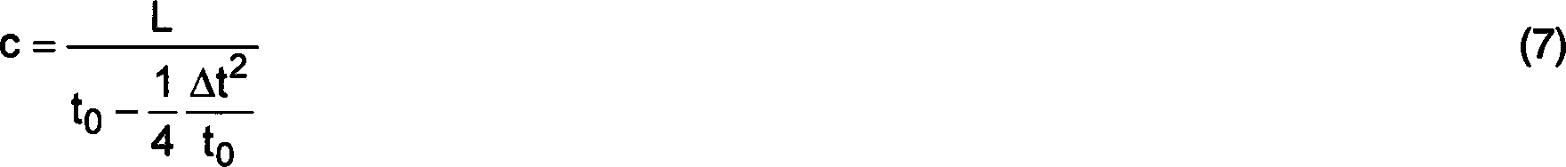
Durch
Einsetzen von Formel (7) in (6) erhält man: 
Hierbei
ist die Konstante C1 der Umrechnungsfaktor
zwischen Strömungsgeschwindigkeit
v und Volumenstrom V .. In die Konstante C, geht im wesentlichen die
Querschnittfläche
von Rohr
Die
Konstante C2 ist für ein rechteckförmiges Strömungsprofil
Aus
den Laufzeiten t45 und t54 oder
dem Laufzeitunterschied Δt
und der mittleren Laufzeit t0 kann der Fluss
im Rohr berechnet werden. Dieses Messprinzip ist unter anderem in
Das
in
Unabhängig von
der Bauformen ist bekannt (z. B. WO 90/05283,
Der Zustand und die Zusammensetzung des zu messenden Gases ändert sich während der Atmung. Die Umgebungsbedingungen werden als Ambient Temperature Pressure (ATP) bezeichnet, die in Body Temperature Pressure Saturated (BTPS) umgerechnet werden können. Ausgeatmetes Gas hat eine Temperatur von etwa 34°C bis 37°C und ist vollständig mit Wasserdampf gesättigt, entspricht also BTPS.Of the Condition and composition of the gas to be measured changes while breathing. The ambient conditions are called Ambient Temperature Pressure (ATP) refers to Saturated in Body Temperature Pressure (BTPS) can be converted. Exhaled gas has a temperature of about 34 ° C to 37 ° C and is completely with Water vapor saturated, corresponds to BTPS.
Darüber hinaus
ist die Rundsing-Technik (Englisch: sing-around technique) beispielsweise
aus der
Zur Analyse insbesondere von sich zeitlich verändernden Funktionen oder Signalen sind beispielsweise die Korrelationsanalyse, die Fourieranalyse oder – transformation, die Kurzzeitfouriertransformation sowie die Wavelettransformation bekannt.to Analysis especially of time-varying functions or signals For example, the correlation analysis, the Fourier analysis or - transformation, the short term Fourier transformation as well as the wavelet transformation known.
Der
Korrelationskoeffizient φ zweier
Funktionen f(t) und g(t), die von der Zeit t abhängen und im Intervall von T1 bis T2 definiert
sind, ist definiert als: 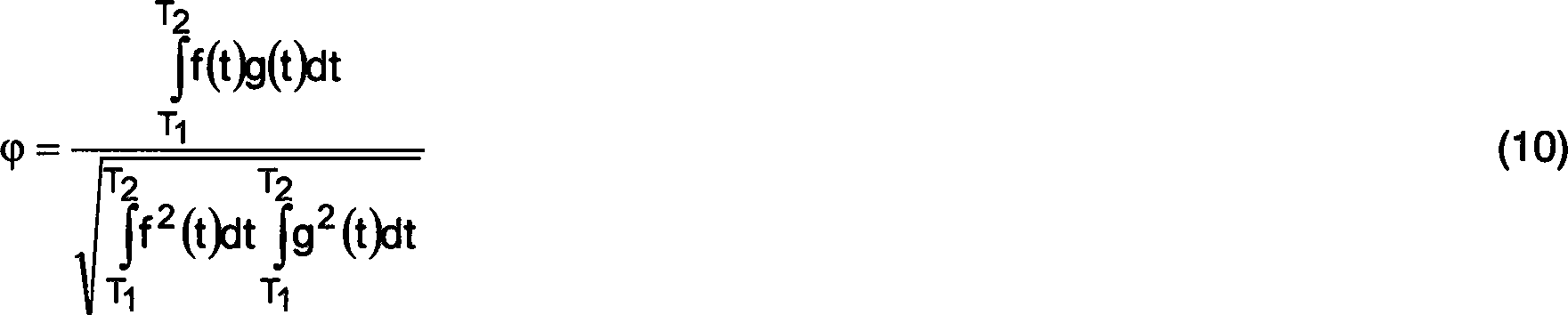
Der Korrelationskoeffizient kann als Maß für die Ähnlichkeit zweier Funktionen interpretiert werden.Of the Correlation coefficient can be used as a measure of the similarity of two functions be interpreted.
Ferner
ist die Kreuzkorrelationsfunktion Φ (KKF) definiert als zeitlicher
Mittelwert des inneren Produkts der beiden um die Zeit τ gegeneinander
verschobenen Funktionen f(t) und g(t): 
Periodische Funktionen mit der Periodendauer (T2 – T1) können durch Fourier-Transformation vollständig als gewichtete Summe von Sinus- und Kosinusfunktionen dargestellt werden. Die Fourierkoeffizienten können als Korrelationsfaktor einer periodischen Funktionen und den Basisvektoren des Fourierraums aufgefasst werden.Periodic functions with the period duration (T 2 - T 1 ) can be represented completely by Fourier transformation as a weighted sum of sine and cosine functions. The Fourier coefficients can be understood as the correlation factor of a periodic function and the basis vectors of the Fourier space.
Die Fourier-Transformation ist prädestiniert, globale Aussagen über ein Signal f(t) zu treffen, da sich ihre Basisfunktionen über den gesamten Zeitbereich erstrecken und keine zeitliche Lokalisierbarkeit zulassen.The Fourier transformation is predestined global statements about to get a signal f (t) because its basic functions are over the extend the entire time range and no temporal localization allow.
Zur Analyse von transienten oder zeitlich begrenzten Signalen wurde die Kurzzeitfouriertransformation (STFT) entwickelt, die eine Entwicklung einer eindimensionalen Zeitfunktionen in die zweidimensionale Zeit-Frequenz-Ebene entspricht. Dabei wird das Signal in als quasistationär angenommene Bereiche aufgeteilt und diese werden unabhängig voneinander einer gefensterten Fourier-Transformation unterzogen (Jürgen Niederholz, Anwendungen der Wavelet-Transformation in Übertragungssystemen, Universität Duisburg, 1999 (http://www.ub.uni-duisburg.de/diss/diss0016/inhalt.htm). Die Fensterfunktionen im Zeitbereich bewirkt ebenfalls eine Fensterung im Frequenzbereich, so dass die STFT über den ganzen Frequenzbereich eine konstante effektive Bandbreite Δω und über den gesamten Zeitbereich eine effektive zeitliche Ausdehnung Δt besitzt.to Analysis of transient or time-limited signals the short-term Fourier transform (STFT) evolves, which is a development a one-dimensional time functions in the two-dimensional time-frequency plane equivalent. The signal is assumed to be quasi-stationary Divided areas and these become independent of a fenestrated Fourier transform subjected (Jürgen Niederholz, Applications of wavelet transformation in transmission systems, university Duisburg, 1999 (http://www.ub.uni-duisburg.de/diss/diss0016/inhalt.htm). The window functions in the time domain also cause a windowing in the frequency domain, giving the STFT over the entire frequency range a constant effective bandwidth Δω and over the entire time range has an effective time extension Δt.
Die konstante effektive Bandbreite und die Beschränkung auf Sinus- und Kosinusfunktionen wurde bei der STFT immer noch als Einschränkung empfunden. Beide Beschränkungen werden bei der Wavelettransformation aufgehoben. Eine allgemeine Einführung in die Wavelettransformation findet sich in (Antje Ohlhoff, Anwendung der Wavelettransformation in der Signalverarbeitung, Universität Bremen, 1996). Die Funktion Ψ(t) stellt ein gültiges Wavelet dar, wenn eine reelle, endliche Konstante CΨ existiert, wobei Ψ ~(ω) die Fouriertransformierte der Funktionen Ψ(t) ist.The constant effective bandwidth and restriction to sine and cosine functions was still perceived as a limitation at STFT. Both restrictions are removed in the wavelet transformation. A general introduction to wavelet transformation can be found in (Antje Ohlhoff, Application of Wavelet Transformation in Signal Processing, University of Bremen, 1996). The function Ψ (t) represents a valid wavelet if a real, finite constant C Ψ exists, where Ψ ~ (ω) is the Fourier transform of the functions Ψ (t).

Eine wesentliche Idee der Wavelettransformation besteht darin, die Funktion Ψ(t) schon geschickt zu wählen und dem zu lösenden Problem anzupassen, so dass die zu analysierenden Funktionen mit einer geringen Anzahl von Wavelets beschrieben werden können. Anders ausgedrückt soll sich nur eine geringe Anzahl von Koeffizienten der Basisfunktionen nennenswert von 0 unterscheiden.A The essential idea of the wavelet transformation consists of the function Ψ (t) already to be sent and the one to be solved Problem adapt so that the features to be analyzed with a small number of wavelets can be described. Different expressed should be only a small number of coefficients of the basis functions significantly different from 0.
Ausgehend von einem Basiswavelet oder Motherwavelet werden die übrigen Basisfunktionen, die eine vollständige Basis für den Funktionsraum bilden, mit einem Translationsparameter b und einem Dilatationsparameter a gemäß Gleichung (13) erzeugt.outgoing from a baseline wavelet or motherwavelet, the remaining basis functions, the one complete base for form the function space, with a translation parameter b and a dilatation parameter a according to the equation (13) generated.
![]()
![]()
Durch
die Gleichung (13) wird die so genannte Güte![]()
![]()
Es ist Aufgabe der Erfindung durch ein intelligentes Auswerteverfahren den Einsatz weniger teurer Bauelemente zu ermöglichen und/oder die Genauigkeit der Laufzeitmessung zu erhöhen.It is task of the invention by an intelligent evaluation allow the use of less expensive components and / or accuracy to increase the transit time measurement.
Diese Aufgabe wird durch die Lehre der unabhängigen Ansprüche gelöst.These The object is achieved by the teaching of the independent claims.
Bevorzugte Ausführungsformen der Erfindung sind Gegenstand der Unteransprüche.preferred embodiments The invention are the subject of the dependent claims.
Vorteilhaft an der Verwendung einer gewichteten Summe von Messwerten eines Wellenpakets zur Bestimmung der zeitlichen Lage des Wellenpakets ist, dass hierdurch ein großer Teil der Energie des Wellenpakets ausgewertet wird, womit die zeitliche Unschärfe klein wird und somit die zeitliche Lage sehr genau bestimmt werden kann.Advantageous using a weighted sum of measurements from a wave packet for determining the temporal position of the wave packet is that thereby a large Part of the energy of the wave packet is evaluated, bringing the temporal fuzziness is small and thus the temporal location can be determined very accurately can.
Vorteilhafterweise wird zum Gewichten eine Vergleichsfunktion verwendet, die der Form des Wellenpakets ähnelt. Eine Sinus- und Kosinusfunktion ähnelt zumindest einer Periode oder wenigen Perioden des Ultraschallpakets.advantageously, For weighting, a comparison function is used, which is the form of the wave packet is similar. A sine and cosine function is similar at least one period or few periods of the ultrasound packet.
Die Verwendung einer Sinus- und einer Kosinusfunktion als Vergleichsfunktionen ist vorteilhaft, weil hierdurch die Lage des Wellenpakets innerhalb einer Periode mit Hilfe einer Arcustangensfunktion bestimmt werden kann, ohne weitere Vergleichsfunktionen zu berechnen.The Using a sine and a cosine function as comparison functions is advantageous because in this way the position of the wave packet within a period using an arctangent function can calculate without further comparison functions.
Die Verwendung einer exponentiellen Hüllkurve, die einer Gauß'schen Glockenkurve ähnelt, passt die Gesamtform der Vergleichsfunktion an die Form eines Wellenpakets an. So ist es möglich, praktisch die gesamte Energie des Wellenpakets auszuwerten und die zeitliche Lage mit einer optimalen Genauigkeit zu bestimmen.The Using an exponential envelope similar to a Gaussian bell curve fits the overall form of the comparison function to the shape of a wave packet at. So it is possible to evaluate practically all the energy of the wave packet and the temporal position with an optimal accuracy.
Die iterative Berechnung der zeitlichen Lage eines Wellenpakets reduziert die Anzahl der notwendigen Berechnungen von Produktsummen und kann so Rechenzeit sparen.The iterative calculation of the temporal position of a wave packet reduced the number of necessary calculations of product sums and can so save computing time.
Um zu prüfen, ob die zeitliche Lage des Wellenpakets nicht um eine oder mehrere Perioden verschoben ist, können die Vergleichsfunktionen um eine oder mehrere Perioden verschoben werden und an diesen Stellen Produktsummen berechnet werden. Zu diesem Zweck kann auch die geometrische Summe zweier Summenprodukten berechnet werden, was mit einem noch geringeren Rechenaufwand verbunden ist. Zum gleichen Zweck können auch die Messwerte direkt mit Bruchteilen von Maxima und/oder Minima verglichen werden.Around to consider, whether the timing of the wave packet is not one or more Periods may be shifted the comparison functions are shifted by one or more periods and product sums are calculated at these locations. To This purpose may also be the geometric sum of two sum products be calculated, resulting in even lower computational effort is. For the same purpose also the measured values directly with fractions of maxima and / or minima be compared.
Eine Maximumsuche in Produktsummen von Messwerten mit einer unterschiedlich weit verschobenen Vergleichsfunktion erlaubt es, den Programmcode kurz zu halten.A Maximum search in product sums of readings with one different far shifted comparison function allows the program code to keep it short.
Eine quadratische Interpolation mittels einer Parabel ist gut geeignet zur Maximumsuche. Außerdem stimmt der Verlauf einer Parabel in der Nähe des Scheitels gut mit dem Verlauf eine Sinus- oder Kosinusfunktion bei einem Maximum überein, da die Taylorentwicklung zweiter Ordnung hier ausreichend ist.A quadratic interpolation by means of a parabola is well suited to the maximum search. It's also true the course of a parabola near the vertex is good with the A sine or cosine function matches at a maximum, since the second-order Taylor expansion is sufficient here.
Im Folgenden werden bevorzugte Ausführungsformen der Erfindung unter Bezugnahme auf die beiliegenden Zeichnungen näher erläutert. Dabei zeigen:in the The following are preferred embodiments of the invention with reference to the accompanying drawings explained in more detail. there demonstrate:
Wie sich aus obigen Formeln, insbesondere Formel (8) ergibt, muss insbesondere der Laufzeitunterschied Δt und die mittlere Laufzeit t0 möglichst exakt gemessen werden. Die anderen Größen, die in den Volumenstrom V eingehen, also C1, C2, L, α, und/oder r, sind weitgehend konstant und können entweder direkt oder über Kalibrationsmessungen bestimmt werden. Auch die Nichtlinearitäten, die dazu führen, dass C1 und C2 von V und damit von Δt abhängen, kann man mit Eichmessungen und Anpassung von Modellkurven wie beispielsweise Polynomen an die Messwerte in den Griff bekommen.As can be seen from the above formulas, in particular formula (8), in particular the transit time difference Δt and the average transit time t 0 must be measured as accurately as possible. The other variables that enter into the volume flow V, ie C 1 , C 2 , L, α, and / or r, are largely constant and can be determined either directly or via calibration measurements. Also, the nonlinearities that cause C 1 and C 2 to depend on V and thus on Δt can be overcome by calibration measurements and fitting model curves such as polynomials to the measured values.
Es verbleibt also das technische Problem, den Laufzeitunterschied Δt oder die Laufzeiten t45 und t54 ausreichend genau zu messen. Dieses Problem ist äquivalent dazu, die zeitliche Lage von Ultraschallpaketen zu bestimmen, die ja Anfang und Ende von Δt festlegen.So there remains the technical problem of measuring the transit time difference Δt or the transit times t 45 and t 54 with sufficient accuracy. This problem is equivalent to determining the timing of ultrasound packets that set the beginning and end of Δt.
Bei den hier beschriebenen Ausführungsformen werden Ultraschallwandler SC.131.XLV (SECO Sensor Consult GmbH) eingesetzt. Für diese Ultraschallwandler wird eine typische Mittenfrequenz von 310kHz, eine typische Bandbreite (±3dB) von ±40kHz sowie eine Schallkeulenbreite von 11° (–3dB) angegeben. Es wird Ultraschall der Frequenz fUS=312,5kHz verwendet, weil es vorteilhaft aber nicht notwendig ist, wenn die Abtastrate fS ein ganzzahliges Vielfaches der Ultraschallfrequenz fUS ist Ultraschall unterliegt bei Normalbedingungen praktisch keiner Dispersion. Für die angestrebte Genauigkeit der Flussmessung muss die zeitliche Lage eines Ultraschallpakets auf etwa eine Nanosekunde genau bestimmt werden. Es ist mit hohen Kosten verbunden, das von einem Ultraschallwandler gelieferte Signal mit einer Abtastrate von einem Gigahertz abtasten und dann das Maximum in den Abtastwerten suchen. Trotzdem wird diese Ausführungsform als eine erfindungsgemäße Ausführungsform betrachtet.In the embodiments described here ultrasonic transducers SC.131.XLV (SECO Sensor Consult GmbH) are used. For these ultrasonic transducers a typical center frequency of 310kHz, a typical bandwidth (± 3dB) of ± 40kHz and a sound lobe width of 11 ° (-3dB) is given. It uses ultrasound of frequency f US = 312.5 kHz, because it is advantageous but not necessary if the sampling rate f S is an integer multiple of the ultrasonic frequency f US Ultrasound is subject to virtually no dispersion under normal conditions. For the desired accuracy of the flow measurement, the temporal position of an ultrasound packet has to be determined exactly to a nanosecond. It involves a high cost to sample the signal supplied by an ultrasonic transducer at a sampling rate of one gigahertz and then seek the maximum in the samples. Nevertheless, this embodiment is considered as an embodiment of the invention.
Es hat sich gezeigt, dass die im folgenden beschriebenen Algorithmen die geforderte zeitliche Genauigkeit von 1ns bereits bei Abtastraten fS = 5 MHz liefern. Mit moderatem technischen und finanziellen Aufwand sind derzeit Abtastraten bis 25 MHz erreichbar.It has been found that the algorithms described below already deliver the required temporal accuracy of 1 ns at sampling rates f S = 5 MHz. With moderate technical and financial expenditure, sampling rates of up to 25 MHz are currently achievable.
Das
vom Analog-Digital-Wandler
Die Messwerte Wj sind rauschbehaftet und weisen einen unbekannten Offset auf. Deshalb liefert die Suche nach lokalen Maxima oder Nullstellen ohne vorherige Signalaufbereitung keine brauchbaren Ergebnisse, selbst wenn die Abtastrate ausreichend hoch wäre.The measured values W j are noisy and have an unknown offset. Therefore, searching for local maxima or zeroes without prior signal conditioning will not yield useful results, even if the sampling rate were sufficiently high.
TiDO AlgorithmusTiDO algorithm
Der
Time Domain Only (TiDO) Algorithmus beruht im wesentlichen auf einer
Bestimmung der Phasenlage einer einzelnen Schwingungsperiode im
Wellenpaket. Die meiste Energie und damit den größten Rauschabstand (SNR, signal
to noise ratio) weist die Schwingung mit der größten Amplitude auf, wobei das
additive Rauschen als konstant über
das gesamte Wellenpaket angenommen wird. Die Laufzeit wird in mehreren Schritten
bestimmt:
1. Im ersten Schritt
1. In the first step
Die
maximal zu erwartete Änderung
der Laufzeiten t45 und t54 liegt
im Bereich von ±20μs, wobei
die Laufzeiten etwa 160μs
betragen. Einschließlich
der Länge
des Schallpakets von etwa 30μs
müssen
also in Schritt
Unter
Berücksichtigung
der Periodizität
des Schallpakets kann der Suchalgorithmus in Schritt
2.
Die Datenpunkte Wj im Intervall
Für eine Abtastfrequenz fS von 5MHz und fUS von 312,5kHz hat S einen Wert von 16.For a sampling frequency f S of 5 MHz and f US of 312.5 kHz, S has a value of 16.
3.
Nun wird die zeitdiskrete zyklische Variante Yτ der
Kreuzkorrelationsfunktion in Schritt 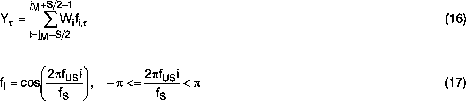
Die
Berechnung von Gleichung (17) erfolgt in Schritt
![]()
![]()
4.
In Yτ wird
nur das Maximum an der Stelle τM in Schritt
5.
Eine Möglichkeit
zur genaueren Maximumsbestimmung ist, eine Parabel Pτ gemäß Formel
(18) in Schritt ![]()
![]()
Die
zeitliche Lage des Ultraschallpakets ergibt sich nun aus Gleichung
(20): ![]()
![]()
Der
TiDO Algorithmus würde
bereits eine ausreichende Genauigkeit liefern. Es ist jedoch nötig, viele Datenpunkte
für den
ersten Schritt
6.
Das in der vorausgehenden Messung bestimmte Maximum τM,vorig wird
in der nachfolgenden Messung als das im ersten Schritt
6. The maximum τ M determined in the preceding measurement is the one in the subsequent measurement as that in the first step
Diese Überlegungen gelten jedoch nur für kleine Flüsse, bei denen Wirbelzonen ausreichend klein sind. An der oberen Messgrenze von 20l/s werden bei einem Rohrdurchmesser von etwa 2 cm Geschwindigkeiten von 65 m/s oder 240 km/h erreicht. Bei hohen Flüssen wurde beobachtet, dass die Laufzeit zwischen zwei aufeinander folgenden Messungen so stark variiert, dass sich die Referenzstelle – also jM beim TiDO Algorithmus oder j93 beim TriTraX Algorithmus – zwischen zwei aufeinander folgenden Messungen um mehr als eine Ultraschallperiode ≈ 3μs unterscheidet. Dies scheint auf Wirbel zurückzuführen zu sein. Diese Wirbel führen zusammen mit der Signalverwehung zu einer um 20dB kleineren Amplitude des Empfangsignals bei einem Fluss von 20 l/s.However, these considerations only apply to small rivers where vortex zones are sufficiently small. At the upper measuring limit of 20l / s, speeds of 65 m / s or 240 km / h are achieved with a pipe diameter of about 2 cm. For high fluxes, it has been observed that the propagation time between two consecutive measurements varies so much that the reference point - ie j M for the TiDO algorithm or j 93 for the TriTraX algorithm - differs between two consecutive measurements by more than one ultrasonic period ≈ 3μs. This seems to be due to vortex. These vortices together with the signal drift lead to a 20 dB smaller amplitude of the received signal at a flow of 20 l / s.
Aufgrund
der Variation der Laufzeit bei hohen Flüssen kann es sinnvoll sein,
in Schritt
Aufgrund der Variation der Laufzeit bei hohen Flüssen kann es bei allen in dieser Schrift beschriebenen Ausführungsformen ferner sinnvoll sein, die Laufzeiten aus mehreren aufeinander folgenden Messungen zu mitteln. Die Anzahl der Bemittelten Messungen kann mit dem Fluss zunehmen.by virtue of The variation of running time at high rivers can be found in all of them Scripture described embodiments Furthermore, make sense, the maturities of several successive To average measurements. The number of averaged measurements can increase with the river.
Nachteilig
ist, dass sich aufgrund des Temperaturverhaltens und der Flussabhängigkeit
der Richtcharakteristik der Ultraschallwandler die in
Nachteilig ist ferner, dass die Maxima der angefitteten Kosinusfunktion fi und der Parabel Pτ umso weiter auseinander liegen, je geringer die Abtastrate fS ist.Another disadvantage is that the lower the sampling rate f S , the farther apart are the maxima of the fitted cosine function fi and the parabola P τ .
TriTraX AlgorithmusTriTraX algorithm
Diese
beiden Probleme soll der Trigonometric Transform by Cross (X) Correlation
(TriTraX) Algorithmus lösen.
Deshalb wird ein Punkt im Wellenpaket benutzt, der die Schwingungsperiode
innerhalb des Ultraschallpakets zuverlässiger identifiziert. In
1.
Im ersten Schritt
Aufgrund
der Variation der Laufzeit bei hohen Flüssen kann es hierbei sinnvoll
sein, in Schritt
2.
Nun wird der Punkt j93 in bestimmt, dessen
Ordinatenwert Wj93 am nächsten bei 0,93*M liegt oder diesen
Wert zum ersten Mal in einem Wellenpaket überschreitet. Zur Optimierung
des Signalrauschabstandes (SNR) wird die Periode mit der größten Amplitude
für die
weiteren Schritte im Algorithmus in Schritt ![]()
![]()
In anderen Ausführungsformen kann jedoch auch ein anderer Ordinatenwert als 93% des Maximums gewählt werden. Insbesondere kann dieser Ordinatenwert auch auf das Minimum, das arithmetische Mittel von Maximum und Minimum, die Differenz zwischen Maximum und Minimum und/oder den Gleichanteil des Wellenpakets bezogen sein. Ist der Ordinatenwert kleiner als der Gleichanteil des Wellenpakets, ist es besser, ein erstmaliges Unterschreiten des Ordinatenwerts als Bezugspunkt zu wählen.In other embodiments however, a different ordinate value than 93% of the maximum can also be selected. In particular, this ordinate value can also be at the minimum, the arithmetic mean of maximum and minimum, the difference between Maximum and minimum and / or the DC component of the wave packet related be. If the ordinate value is smaller than the DC component of the wave packet, it is better, a first falling below the ordinate value as a reference point.
3.
Nun werden die Korrelationskoeffizienten φC und φS zwischen cj und
Wj bzw. sj und Wj in Schritten 
Die
Formeln (22) und (23) werden in Schritten
Die
Berechnung der Korrelationskoeffizienten entspricht mathematisch
der Bestimmung eines komplexen Koeffizienten φC +
iφS einer diskreten Fourierentwicklung: ![]()
![]()
4.
An Stelle dieser komplexen Darstellung kann auch der Betrag um die
Phase φ der
Schwingung angegeben werden, wobei die Phase φ mittels der arctan-Funktion
berechnet werden kann. Diese ist jedoch nur in einem Intervall der
Länge π eindeutig.
Durch Berücksichtigung
der Vorzeichen von φC und φS kann dieses Intervall auf 2π ausgedehnt
werden:
In entsprechender Weise ist arc cot2(φC;φS) definiert.Correspondingly, arc cot2 (φ C ; φ S ) is defined.
Die
Phase φ wird
in Schritt
5.
Die Laufzeit wird aus Formel 26 berechnet: ![]()
![]()
6. Analog zum oben beschriebenen TiDO Algorithmus wird wieder die Annahme in6th Analogous to the above-described TiDO algorithm is again the assumption in
Schritt ![]()
![]()
Wie beim TiDO Algorithmus kann zunächst ein lokales Maximum gesucht werden und dann im Abstand von ±nS benachbarte lokale Maxima überprüft werden, um das globale Maximum zu finden, wobei n eine ganze Zahl ist.As at the TiDO algorithm can first a local maximum are searched for and then adjacent to each other at ± nS local maxima are checked to find the global maximum, where n is an integer.
Sowohl der TiDO als auch der TriTraX Algorithmus haben den Nachteil, dass nur eine Periode des gesamten Ultraschallpakets ausgewertet wird, was zu einer suboptimalen Genauigkeit der Bestimmung der Laufzeit führt.Either The TiDO as well as the TriTraX algorithm have the disadvantage that only one period of the entire ultrasound packet is evaluated, resulting in a sub-optimal accuracy of the determination of the transit time leads.
WaveTraX AlgorithmusWaveTraX algorithm
Der Wavelet Transform by Cross (X) Correlation Algorithmus ermöglicht es, eine dem Signal angepasste Basis zu verwenden. Das Motherwavelet wird so gewählt, dass es möglichst genau einem Ultraschallpaket entspricht.Of the Wavelet Transform by Cross (X) correlation algorithm allows to use a base adapted to the signal. The mother wavelet is chosen that it is possible exactly equivalent to an ultrasound package.
Aus
einem nichtlinearen Fit über
ein typisches Ultraschallpaket ergab sich das Mothersinus- und -cosinuswavelet
zu: 
Die
Motherwavelets werden in den Schritten
1.
Zunächst
wird in Schritt
![]()
![]()
Die
Kreuzkorrelationsfunktion KWS,τ Erreicht ihren Maximalwert,
wenn die Lage des Mothersinuswavelets und des abgetasteten Ultraschallpakets
möglichst
guter Übereinstimmung
ist. Eine Maximumsuche in KWS,τ liefert die Stelle τM des
Maximums der Kreuzkorrelationsfunktion. Das Maximum der Kreuzkorrelationsfunktion ist
gleichzeitig der Korrelationsfaktor φWS zwischen
den Messwerten und dem Mothersinuswavelet:
In
diesem Zusammenhang soll schon jetzt darauf hingewiesen werden,
dass in einer verfeinerten Ausführungsform
in die Maximumsuche eine Iteration eingebaut werden kann, gemäß der in
Gleichung (30) bei einem beliebigen r, also nicht unbedingt bei τM aber
beispielsweise bei τM,vorig, dem τM der
vorangehenden Messung, begonnen wird. Aus Gleichung (34) wird dann
in Schritt
2.
Die exakte Phasenlage des Wellenpaket wird ähnlich dem TriTraX Algorithmus
aus den Korrelationsfaktoren zwischen den Messwerten und dem Mothersinus-
und -cosinuswavelet in Schritt ![]()
![]()
3.
Aus den Korrelationsfaktoren wird die Phase φW bestimmt:
Die
Laufzeit ergibt sich aus: ![]()
![]()
Steht
bereits ein Schätzwert τS für den Index τM des
Maximums zur Verfügung,
so kann für
die gleichen Messwerte Wj ein verbesserter
Schätzwert τB aus ![]()
![]()

τB gibt
nicht notwendigerweise exakt die Phasenlage des Ultraschallpakets
an, weil die Exponentialfunktion in den beiden Motherwavelets eine
Hüllkurve
für die
Sinus- bzw. Kosinus-Anteile
darstellt und diese verzerrt. Stimmt die Hüllkurve des empfangenen Ultraschallpakets
(vgl.
Gemäß Gleichung
(29) wird das Maximum des Korrelationsfaktors φWS mit
dem Mothersinuswavelet (vgl. Gleichung (30)) bestimmt. Aufgrund
der begrenzten Abtastrate weicht dieses Maximum optimalerweise um
bis zu ±1/(2fS) von der Phasenlage des Ultraschallpakets
ab. Die tatsächlichen
Abweichungen sind noch etwas größer. Die
Nachkommastellen vom Index τM, der ja zunächst ganzzahlig ist, werden
sozusagen mit Hilfe des Motherkosinuswavelets berechnet. Solange
das Motherkosinuswavelet noch eine Verschiebung liefert, deren Betrag
größer als
ein Schwellenwert ist, kann man davon ausgehen, dass noch keine
ausreichende Konvergenz erreicht wurde. Eine sinnvolle Wahl dieses
Schwellenwerts ist 1/fS. Für S = 16
ergibt sich eine betragsmäßige Obergrenze
für φW von π/8
oder 22,5° und
damit
Diese Obergrenze kann für den optimalen Fall für φW auf 11,25° und für φWC/φWS auf 0,199 abgesenkt werden.This upper limit can be lowered to 11.25 ° for the optimum case for φ W and to 0.199 for φ WC / φ WS .
Falls
diese Obergrenze überschritten
wird und deshalb ein weiterer Iterationsschritt durchgeführt werden
soll, wird τB = τM zwischen den beiden Iterationsschritten
in Schritt
In
einer Ausführungsform,
in der ein Mikroprozessor verwendet wird, in dem die Berechnung
der Arkustangens- oder Arkuskotangensfunktion nicht effizient implementiert
ist und deshalb lange dauert, können diese
Funktionen in Schritt
Wie
oben erwähnt,
führt diese
Iteration lediglich zu einem lokalen Maximum von φWS, das nicht notwendigerweise gleich dem
globalen Maximum von φWS entspricht. Auch ist der Abstand zweier
lokaler Maxima nicht immer exakt gleich der Periodendauer des Ultraschalls,
weil die Exponentialfunktion die Sinus- und Kosinusfunktion verzerrt.
Insofern kann die Maximumsuche dahingehend modifiziert werden, dass
abwechselnd ein Iterationsschritt gemäß Gleichung (34) und eine Überprüfung der
beiden benachbarten lokalen Maxima durchgeführt wird. Die beiden Korrelationskoeffizienten φWC und φWS wurden an der Stelle τS berechnet.
Bei round(τB) werden die Korrelationskoeffizienten erst
im nächsten
Iterationsschritt berechnet. Die Funktionen round() rundet eine
Fließkommazahl
auf die nächste
ganze Zahl. Da τS anfangs lediglich eine Überlappung zwischen dem Ultraschallpaket
und den Wavelets sicherstellen muss, kann φWS am
Anfang der Iterationen auch negativ sein. Insofern bietet sich an,
zur Maximumsuche den Betrag B(τ)
zu verwenden, dessen Berechnung beispielhaft in Schritt ![]()
![]()
Ein
Betrag wird aber auch in Schritten
Die
Zahl S, die einen gebrochenen Anteil aufweisen kann, gibt die Zahl
von Messwerten in einer Ultraschallperiode an. Deshalb sollen die
Beträge
B(round(τS ± S))
in Schritten
In
einer weiteren Ausführungsform
können,
wenn der Betrag B(round(τS ± S))
größer als
der Betrag B(τS) ist, in dieser Richtung weitere Stellen
round(τS ± πS) hinsichtlich
des Betrags B(round(τs ± πS)) der Korrelationsfaktoren
in Schritten
Solche
Feinheiten sind bei einer hohen Messrate der Flussgeschwindigkeit
für die
bei menschlicher Atmung typischerweise maximal zu erwartenden Beschleunigungen
im Gasstrom weniger wichtig. Dann unterscheiden sich die Phasenlagen
zweier Ultraschallpakete zweier aufeinander folgender Messungen
wenig. Deshalb liegt τM bereits ausreichend nah bei τM,vorig,
der Stelle des Maximums bei der vorhergehenden Messung, so dass,
wenn τM,vorig als erster Schätzwert verwendet wird, lediglich
ein Iterationsschritt nötig
ist, um τM zu bestimmen. In einem nicht ganz so optimalen
Fall, wenn die Bedingung in Schritt
Um
festzustellen, ob sich ein Schätzwert τS oder
ein verbesserter Schätzwert τB sich
bereits in der richtigen Ultraschallperiode befindet, kann der Betrag
B(τS) in Schritt
Dieser Betrag muss über dem Grenzwert CB liegen, der von der Flussgeschwindigkeit und damit vom Laufzeitunterschied Δt aber auch von anderen Parametern wie dem Alter der Ultraschallwandler abhängen kann. Aufgrund des Intensitätsabfalls bei hohen Flüssen wird CB mit zunehmendem Fluss abnehmen.This amount must be above the limit value C B , which may depend on the flow velocity and thus on the transit time difference Δt but also on other parameters such as the age of the ultrasonic transducers. Due to the drop in intensity at high fluxes, C B will decrease with increasing flux.
Eine
weitere Möglichkeit,
bei dem WaveTraX Algorithmus die richtige Periode zu bestimmen,
besteht in einer Kombination mit dem TriTraX Algorithmus. So kann
zunächst
der Index j93 bestimmt werden, dessen Ordinatenwert
Wj93 am nächsten bei 0,93*M liegt. Hierbei
ist M das Maximum der Messdaten, die gerade ausgewertet werden (vgl.
Schritt ![]()
![]()
P-SEX AlgorithmusP-SEX algorithm
Es hat sich auch der WaveTraX Algorithmus insbesondere bei einer wesentlichen Reduzierung der Signalamplitude und Signalverzerrungen aufgrund von Turbulenzen bei hohen Flüssen als nur unzureichend robust herausgestellt. Daher wurde ein neuer Algorithmus mit der Bezeichnung P-SEX (Phase-Shifted Excitation and Cross Correlation (X)) entwickelt.It The WaveTraX algorithm has also been found to be essential Reduction of signal amplitude and signal distortion due to turbulence at high rivers proved to be only insufficiently robust. Therefore, a new one became Algorithm named P-SEX (Phase-Shifted Excitation and Cross Correlation (X)).
Die
Anregung der Ultraschallwandler erfolgt über eine in
Das
bei ruhendem Medium empfangene Signal, das beispielhaft in
1.
Daher wird als Referenzfunktion für die Berechnung einer Kreuzkorrelationsfunktion
nicht wie beim WaveTraX Algorithmus eine Funktion verwendet, die
dem empfangenen Signal ähnelt.
Vielmehr wird die in
2. Noch besser ist es, das linke der beiden betragsmäßig größten Minima, das im Folgenden als linkes Minimum τIM bezeichnet wird, zu betrachten. Der Unterschied zum betragsmäßig nächstkleineren Minimum beträgt fast 50% im Gegensatz zu den 23% bei Betrachtung des Maximums.2. It is even better to consider the left of the two absolute minimums, which is referred to below as the left minimum τ IM . The difference to the next smaller minimum amount is almost 50%, in contrast to the 23% when considering the maximum.
Es
wurde aber beobachtet, dass das Minimum links vom linken Minimum
betragsmäßig sehr
groß wird – insbesondere
größer als
der Betrag des (bei geringen Flüssen
globalen) Minimums rechts des linken Minimums τIM.
Gleichzeitig führt
die bei hohen Flüssen
veränderte
Form der P-SEX Kreuzkorrelationsfunktion dazu, dass das linke Minimum τIM zum
globalen Minimum betragsmäßig anwächst und
wohl definiert ist (
Es
wird also in der Kreuzkorrelationsfunktion KKF gemäß Gleichung
(41) das globale Minimum y1 an der Stelle τ gesucht.
Dann werden die beiden benachbarten Minima y0 und
y2 gemäß Gleichungen
(![]()
![]()
Im Ergebnis sucht dieser Algorithmus prinzipiell das linke Minimum. Der Laufzeitunterschied, ab dem das linke Minimum zum globalen Minimum angewachsen ist, beträgt etwa 5μs. Im Vergleich hierzu beträgt der Laufzeitunterschied bei einem maximalen Fluss von 20 l/s bei der aktuellen Dimensionierung des Rohrquerschnitts etwa 24μs. Damit lässt sich die grobe Position des Schallpakets gut bestimmen.in the As a result, this algorithm basically looks for the left minimum. The runtime difference, from which the left minimum to the global minimum has grown about 5μs. Compared to this amounts the difference in transit time at a maximum flow of 20 l / s the current dimensioning of the pipe cross-section about 24μs. In order to let yourself determine the rough position of the sound packet well.
3.
Zur exakten Phasenbestimmung wird in der Kreuzkorrelationsfunktion
die cos-Periode
(–π ... π), die auf
das gesuchte Minimum folgt, ausgewählt:
4.
Die Wi werden analog zu Schritten
5.
Anschließend
wird entsprechend dem Schritt
6.
Schließlich
wird die Laufzeit t aus Gleichung (46) berechnet: ![]()
![]()
Neben den oben beschriebenen Algorithmen sind weitere Abwandlungen denkbar. Insbesondere kann das empfangene Ultraschallsignal mit einer Referenzfunktion korreliert oder gefaltet werden, die die Inverse des Übertragungswegs darstellt. Je nach Definition des Übertragungswegs, also beispielsweise Leistungsverstärker-Ultraschallwandler-Luft-Ultraschallwandler oder Triggerimpuls-Rechteckgenerator-Leistungsverstärker-Ultraschallwandler-Luft-Ultraschallwandler kann das Ergebnis der Faltung oder Korrelation beispielsweise ein Impuls oder eine Rechteck-Wechselspannung sein. Besonders vorteilhaft sind auch Korrelationsfunktionen, die das empfangene Ultraschallsignal näherungsweise in eine Dirac'sche Deltafunktion verwandeln, wobei Idealerweise nur der Wert eines Zeitintervalls nennenswert von Null verschieden ist.Next The algorithms described above, further modifications are conceivable. In particular, the received ultrasonic signal with a reference function be correlated or folded, which is the inverse of the transmission path represents. Depending on the definition of the transmission path, for example Power amplifier ultrasound transducer-air ultrasonic transducers or Trigger Pulse Rectangle Generator Power Amplifier Ultrasonic Transducer Air Ultrasonic Transducer For example, the result of convolution or correlation can be Pulse or a square-wave AC voltage be. Also particularly advantageous are correlation functions that the received ultrasonic signal is approximately in a Dirac delta function ideally, only the value of a time interval is significantly different from zero.
Zur Bestimmung des richtigen Intervalls kann eine andere Korrelationsfunktion eingesetzt werden als zur Bestimmung der Phase.to Determining the right interval can have a different correlation function used as for the determination of the phase.
Insbesondere
während
des Empfangsbetriebs müssen
die Wandler von der Treiberschaltung getrennt werden, was beispielsweise
durch die Schalter
Im
Empfangsbetrieb werden die von den Ultraschallwandlern gelieferten
elektrischen Signale durch die Analog-Digital-Wandler
Insbesondere
das Rohr
Obwohl
die Lage der ausgesandten Ultraschallpakete leicht zu bestimmen
ist, weil ja der Mikroprozessor
Aufgrund
der in der Zwischenzeit zur Verfügung
stehenden Ultraschallwandler können
kurze Ultraschallimpulse erzeugt werden. So beträgt die Länge des in
Soweit ausreichend Speicher und Rechenleistung zur Verfügung stehen, können sofort nach der Aufzeichnung von zwei ersten Ultraschallpaketen die beiden nächsten Ultraschallpakete gesendet werden. Während der Laufzeit der nächsten Ultraschallpakete kann die Auswertung der Aufzeichnung der ersten Ultraschallpakete erfolgen. Die Flussgeschwindigkeit, die aus den beiden ersten Ultraschallpaketen berechnet wird, kann dann kurz vor der Aufzeichnung der beiden nächsten Ultraschallpakete zur Verfügung stehen. So können die oben angegebenen Abtastraten von 6,25 kHz für die Geschwindigkeitsmessung erreicht werden.So far sufficient memory and computing power are available immediately after recording two first ultrasound packets the two next Ultrasonic packets are sent. During the term of the next ultrasound packages may be the evaluation of the record of the first ultrasound packets respectively. The flow velocity coming from the first two ultrasound packages can then be calculated just before recording the next two ultrasound packets to disposal stand. So can the 6.25 kHz sampling rates given above for speed measurement be achieved.
Bei jeder der oben beschriebenen Ausführungsformen kann als Plausibilitätskontrolle der Unterschied der aus zwei aufeinander folgenden Messungen bestimmten Geschwindigkeit ausgewertet werden. Dieser muss betragsmäßig kleiner als eine maximale Änderungsrate der Geschwindigkeit multipliziert mit dem zeitlichen Abstand der beiden Messungen liegen. Falls dies nicht der Fall ist, kann eine Fehlermeldung ausgegeben werden und/oder der jüngere Messwert verworfen werden.at Any of the embodiments described above may serve as a plausibility check the difference determined from two consecutive measurements Speed are evaluated. This must be smaller in size as a maximum rate of change the speed multiplied by the time interval of the lie two measurements. If this is not the case, one can Error message will be issued and / or the younger reading will be discarded.
Obwohl die bevorzugte Ausführungsform oben im Zusammenhang mit Luft beschrieben wurde, kann die Erfindung bei jedem anderen Fluid eingesetzt werden, um eine Flussgeschwindigkeit oder ein Volumenstrom zu bestimmen.Even though the preferred embodiment has been described above in connection with air, the invention be used with any other fluid at a flow rate or to determine a volumetric flow.
Die Erfindung wurde zuvor anhand von bevorzugten Ausführungsformen näher erläutert. Für einen Fachmann ist jedoch offensichtlich, dass verschiedene Abwandlungen und Modifikationen gemacht werden können, ohne vom Geist der Erfindung abzuweichen. Deshalb wird der Schutzbereich durch die nachfolgenden Ansprüche und ihre Äquivalente festgelegt.The The invention was previously based on preferred embodiments explained in more detail. For a specialist However, it is obvious that various modifications and modifications can be made without departing from the spirit of the invention. Therefore, the scope of protection by the following claims and their equivalents established.
Mathematische Symbole:Mathematical symbols:
-
- α:α:
- Winkel zwischen Achsen 3 und 6Angle between axes 3 and 6
- c:c:
- Schallgeschwindigkeit im ruhenden Mediumspeed of sound in the dormant medium
- CB, C1, C2:C B , C 1 , C 2 :
- Konstantenconstants
- Sj, Cj:S j , C j :
- "Abtastwerte" des Mothersinus- und -cosinuswavelets"Samples" of the mother sine and cosine wavelet
- fUS:f US :
- Ultraschallfrequenzultrasonic frequency
- fS:f S:
- Abtastrate sampling rate
- f(t), g(t):f (t), g (t):
- zeitabhängige Funktionentime-dependent functions
- j:j:
- Index der MesswerteIndex of the measured values
- jM:j M :
- Index von MIndex of M
- L:L:
- Abstand der UltraschallwandlerDistance of the ultrasonic transducers
- M:M:
- Maximum der Wj Maximum of W j
- φC, φS:φ C , φ S :
- Korrelationskoeffizientencorrelation coefficients
- φWS, φWC:φ WS , φ WC :
- Korrelationskoeffizientencorrelation coefficients
- φW:φ W :
- Phasephase
- Δt:.delta.t:
- LaufzeitunterschiedSkew
- t0:t 0 :
- mittlere Laufzeitmedium term
- t45, t54 t 45 , t 54
- SchalllaufzeitenSound transit times
- Φ:Φ:
- KreuzkorrelationsfunktionCross-correlation function
- r:r:
-
Radius von Rohr
2 Radius of pipe2 - S:S:
- fS/fUS (in einer Ausführungsform 16)f S / f US (in one embodiment 16)
- v:v:
- Strömungsgeschwindigkeit des Mediumsflow rate of the medium
- V .:V .:
- Volumenstromflow
- Wj W j
- Messwertereadings
- Yτ:Y τ :
- zeitdiskrete zyklische Variantediscrete-time cyclic variant
- τM:τ M :
- (interpolierter) Index(interpolated) index
- τS:τ S :
- (ganzzahliger) Schätzwert für τM (integer) estimate for τ M
- τB:τ B :
- verbesserter Schätzwert für τM improved estimate for τ M
- 1, 111, 11
- Flussmessgerätflow meter
- 22
- Rohrpipe
- 33
- Achseaxis
- 4, 5, 14, 154, 5, 14, 15
- Ultraschallwandlerultrasound transducer
- 6 6
- Achseaxis
- 77
- Treiberschaltungdriver circuit
- 88th
- Schalterswitch
- 99
- Mikroprozessormicroprocessor
- 94, 9594 95
- Analog-Digital-WandlerAnalog to digital converter
- 1212
- waagrechten Schenkelhorizontal leg
- 1313
- Achseaxis
- 17,1817.18
- senkrechter Schenkelvertical leg
- 3131
- Schallpaketsound package
- M1, M2, M3, M4, M5, M6, M7, M8M1, M2, M3, M4, M5, M6, M7, M8
- Maximamaxima
- 41–8341-83
- Schrittesteps
Claims (23)
Priority Applications (5)
| Application Number | Priority Date | Filing Date | Title |
|---|---|---|---|
| DE102005015456A DE102005015456A1 (en) | 2005-04-04 | 2005-04-04 | Wave packet`s temporal position determining method for e.g. spirometer, involves computing sum of product as product from value of comparison function and measurement value, and computing temporal position from sum of product |
| PCT/DE2006/000544 WO2006105761A2 (en) | 2005-04-04 | 2006-03-28 | Method for determining the temporal position of a wave packet and flow measuring device |
| EP06722696.9A EP1875380B1 (en) | 2005-04-04 | 2006-03-28 | Method for determining the temporal position of a wave packet and flow measuring device |
| US11/910,562 US8103461B2 (en) | 2005-04-04 | 2006-03-28 | Method for determining the temporal position of a wave packet and flow measuring device |
| DE112006001498T DE112006001498A5 (en) | 2005-04-04 | 2006-03-28 | Method for determining the timing of a wave packet and flow meter |
Applications Claiming Priority (1)
| Application Number | Priority Date | Filing Date | Title |
|---|---|---|---|
| DE102005015456A DE102005015456A1 (en) | 2005-04-04 | 2005-04-04 | Wave packet`s temporal position determining method for e.g. spirometer, involves computing sum of product as product from value of comparison function and measurement value, and computing temporal position from sum of product |
Publications (1)
| Publication Number | Publication Date |
|---|---|
| DE102005015456A1 true DE102005015456A1 (en) | 2006-10-05 |
Family
ID=36954910
Family Applications (2)
| Application Number | Title | Priority Date | Filing Date |
|---|---|---|---|
| DE102005015456A Withdrawn DE102005015456A1 (en) | 2005-04-04 | 2005-04-04 | Wave packet`s temporal position determining method for e.g. spirometer, involves computing sum of product as product from value of comparison function and measurement value, and computing temporal position from sum of product |
| DE112006001498T Withdrawn DE112006001498A5 (en) | 2005-04-04 | 2006-03-28 | Method for determining the timing of a wave packet and flow meter |
Family Applications After (1)
| Application Number | Title | Priority Date | Filing Date |
|---|---|---|---|
| DE112006001498T Withdrawn DE112006001498A5 (en) | 2005-04-04 | 2006-03-28 | Method for determining the timing of a wave packet and flow meter |
Country Status (4)
| Country | Link |
|---|---|
| US (1) | US8103461B2 (en) |
| EP (1) | EP1875380B1 (en) |
| DE (2) | DE102005015456A1 (en) |
| WO (1) | WO2006105761A2 (en) |
Cited By (6)
| Publication number | Priority date | Publication date | Assignee | Title |
|---|---|---|---|---|
| DE102010063937A1 (en) | 2010-12-22 | 2012-06-28 | Sonotec Ultraschallsensorik Halle Gmbh | Method for determining run time of ultrasonic pulse, involves transforming wavelet from separated ultrasonic pulse and reference pulse based on generated wavelet, and determining run time of ultrasonic pulse from wavelet transformation |
| DE102012202189B3 (en) * | 2012-02-14 | 2013-02-07 | Sonotec Ultraschallsensorik Halle Gmbh | Method and device for wavelet-based transit time measurement of ultrasound pulses |
| WO2016184709A1 (en) * | 2015-05-18 | 2016-11-24 | Endress+Hauser Flowtec Ag | Measuring system for measuring at least one parameter of a fluid |
| US10605779B2 (en) | 2015-02-16 | 2020-03-31 | Sensaction Ag | Method for determining properties of a medium and device for determining properties of a medium |
| DE102018009664A1 (en) * | 2018-12-08 | 2020-06-10 | Diehl Metering Gmbh | Method for evaluating measurement data series of an ultrasonic flow measuring device and ultrasonic flow measuring device |
| DE102022100677A1 (en) | 2022-01-12 | 2023-07-13 | Diehl Metering Gmbh | Method and measuring device for determining a measured variable relating to a flow |
Families Citing this family (40)
| Publication number | Priority date | Publication date | Assignee | Title |
|---|---|---|---|---|
| US9677555B2 (en) | 2011-12-21 | 2017-06-13 | Deka Products Limited Partnership | System, method, and apparatus for infusing fluid |
| US9151646B2 (en) | 2011-12-21 | 2015-10-06 | Deka Products Limited Partnership | System, method, and apparatus for monitoring, regulating, or controlling fluid flow |
| DK2771712T3 (en) | 2011-10-28 | 2023-06-26 | Decision Sciences Int Corp | ENCODED SPREAD SPECTRUM WAVEFORMS IN ULTRASONIC IMAGES |
| US9675756B2 (en) | 2011-12-21 | 2017-06-13 | Deka Products Limited Partnership | Apparatus for infusing fluid |
| US9724467B2 (en) | 2011-12-21 | 2017-08-08 | Deka Products Limited Partnership | Flow meter |
| US9746093B2 (en) | 2011-12-21 | 2017-08-29 | Deka Products Limited Partnership | Flow meter and related system and apparatus |
| US9746094B2 (en) | 2011-12-21 | 2017-08-29 | Deka Products Limited Partnership | Flow meter having a background pattern with first and second portions |
| US10563681B2 (en) | 2011-12-21 | 2020-02-18 | Deka Products Limited Partnership | System, method, and apparatus for clamping |
| US11295846B2 (en) | 2011-12-21 | 2022-04-05 | Deka Products Limited Partnership | System, method, and apparatus for infusing fluid |
| US9435455B2 (en) | 2011-12-21 | 2016-09-06 | Deka Products Limited Partnership | System, method, and apparatus for monitoring, regulating, or controlling fluid flow |
| US9372486B2 (en) | 2011-12-21 | 2016-06-21 | Deka Products Limited Partnership | System, method, and apparatus for monitoring, regulating, or controlling fluid flow |
| US10488848B2 (en) | 2011-12-21 | 2019-11-26 | Deka Products Limited Partnership | System, method, and apparatus for monitoring, regulating, or controlling fluid flow |
| US10228683B2 (en) | 2011-12-21 | 2019-03-12 | Deka Products Limited Partnership | System, method, and apparatus for monitoring, regulating, or controlling fluid flow |
| US10508937B2 (en) * | 2012-04-12 | 2019-12-17 | Texas Instruments Incorporated | Ultrasonic flow meter |
| US9689726B2 (en) * | 2012-07-09 | 2017-06-27 | Texas Instruments Incorporated | Flow meter |
| US9759343B2 (en) | 2012-12-21 | 2017-09-12 | Deka Products Limited Partnership | Flow meter using a dynamic background image |
| US9844359B2 (en) | 2013-09-13 | 2017-12-19 | Decision Sciences Medical Company, LLC | Coherent spread-spectrum coded waveforms in synthetic aperture image formation |
| USD751689S1 (en) | 2013-11-06 | 2016-03-15 | Deka Products Limited Partnership | Apparatus to control fluid flow through a tube |
| USD745661S1 (en) | 2013-11-06 | 2015-12-15 | Deka Products Limited Partnership | Apparatus to control fluid flow through a tube |
| USD751690S1 (en) | 2013-11-06 | 2016-03-15 | Deka Products Limited Partnership | Apparatus to control fluid flow through a tube |
| USD752209S1 (en) | 2013-11-06 | 2016-03-22 | Deka Products Limited Partnership | Apparatus to control fluid flow through a tube |
| USD749206S1 (en) | 2013-11-06 | 2016-02-09 | Deka Products Limited Partnership | Apparatus to control fluid flow through a tube |
| AU2015318119B2 (en) | 2014-09-18 | 2019-07-11 | Deka Products Limited Partnership | Apparatus and method for infusing fluid through a tube by appropriately heating the tube |
| US10743838B2 (en) | 2015-02-25 | 2020-08-18 | Decision Sciences Medical Company, LLC | Acoustic signal transmission couplants and coupling mediums |
| WO2017062890A1 (en) | 2015-10-08 | 2017-04-13 | Decision Sciences Medical Company, LLC | Acoustic orthopedic tracking system and methods |
| USD905848S1 (en) | 2016-01-28 | 2020-12-22 | Deka Products Limited Partnership | Apparatus to control fluid flow through a tube |
| CN113855905B (en) | 2016-01-28 | 2024-01-12 | 德卡产品有限公司 | Drip chambers and equipment used to infuse fluids into patients |
| JP6500243B2 (en) * | 2016-03-29 | 2019-04-17 | パナソニックIpマネジメント株式会社 | Flow measurement device |
| USD854145S1 (en) | 2016-05-25 | 2019-07-16 | Deka Products Limited Partnership | Apparatus to control fluid flow through a tube |
| AU2019280858B2 (en) | 2018-06-08 | 2025-02-13 | Orbis Intelligent Systems, Inc. | Pipe sensors |
| US12152954B2 (en) | 2018-06-08 | 2024-11-26 | Orbis Intelligent Systems, Inc. | Detection device for a fluid conduit or fluid dispensing device |
| US11733115B2 (en) | 2018-06-08 | 2023-08-22 | Orbis Intelligent Systems, Inc. | Detection devices for determining one or more pipe conditions via at least one acoustic sensor and including connection features to connect with an insert |
| US11698314B2 (en) | 2018-06-08 | 2023-07-11 | Orbis Intelligent Systems, Inc. | Detection device for a fluid conduit or fluid dispensing device |
| MX2021001825A (en) | 2018-08-16 | 2021-07-15 | Deka Products Lp | Medical pump. |
| CN111352099B (en) * | 2018-12-20 | 2022-05-10 | 宁波大学科学技术学院 | A Time Delay Estimation Method Based on Phase Decomposition of Cross-correlation Signals |
| US12017389B2 (en) | 2019-03-06 | 2024-06-25 | Decision Sciences Medical Company, LLC | Methods for manufacturing and distributing semi-rigid acoustic coupling articles and packaging for ultrasound imaging |
| WO2020219705A1 (en) | 2019-04-23 | 2020-10-29 | Allan Wegner | Semi-rigid acoustic coupling articles for ultrasound diagnostic and treatment applications |
| USD964563S1 (en) | 2019-07-26 | 2022-09-20 | Deka Products Limited Partnership | Medical flow clamp |
| WO2021021596A1 (en) | 2019-07-26 | 2021-02-04 | Deka Products Limited Partnership | Apparatus for monitoring, regulating, or controlling fluid flow |
| CA3202517A1 (en) | 2020-11-13 | 2022-05-19 | Decision Sciences Medical Company, LLC | Systems and methods for synthetic aperture ultrasound imaging of an object |
Citations (14)
| Publication number | Priority date | Publication date | Assignee | Title |
|---|---|---|---|---|
| EP0051293A1 (en) * | 1980-10-31 | 1982-05-12 | Kabushiki Kaisha Toshiba | Respiration flowmeter |
| EP0243515A1 (en) * | 1986-04-26 | 1987-11-04 | MMT-Medizin Messtechnik U. Spiegelhauer KG | Device for measuring the flow rate of gas or gas mixtures in an open tube |
| CH669463A5 (en) * | 1985-03-21 | 1989-03-15 | Walter Guggenbuehl Prof Dr | Gas flow and temp. measuring device - uses ultrasonic pulses transmitted simultaneously in opposite directions at angle to gas flow |
| WO1990005283A1 (en) * | 1988-10-31 | 1990-05-17 | Jerker Delsing | Method and apparatus for measuring mass flow |
| US5509414A (en) * | 1994-09-27 | 1996-04-23 | Hok Instrument Ab | Apparatus and method for non-contacting detection of respiration |
| EP0713080A1 (en) * | 1994-10-24 | 1996-05-22 | DELSING, Jerker | Method and device for measuring with sing-around technique |
| EP0597060B1 (en) * | 1992-06-03 | 1997-04-16 | NDD Medizintechnik GmbH | Spirometer, in particular ultrasound spirometer |
| WO1998031989A1 (en) * | 1997-01-16 | 1998-07-23 | Foster-Miller, Inc. | A flow analysis system and method |
| WO2000026618A1 (en) * | 1998-11-03 | 2000-05-11 | D-Flow Group Ab | Device for temperature compensation in an acoustic flow meter |
| US6261238B1 (en) * | 1996-10-04 | 2001-07-17 | Karmel Medical Acoustic Technologies, Ltd. | Phonopneumograph system |
| US6279379B1 (en) * | 1998-04-17 | 2001-08-28 | Lorex Industries, Inc. | Apparatus and methods for performing acoustical measurements |
| US20030018276A1 (en) * | 2000-10-06 | 2003-01-23 | Mansy Hansen A. | Acoustic detection of endotracheal tube location |
| EP1279368A2 (en) * | 2001-07-17 | 2003-01-29 | ndd Medizintechnik AG | Device for measuring the flow velocity and/or molecular mass of gases ou gasmixtures |
| EP0797105B1 (en) * | 1996-03-21 | 2004-08-11 | Siemens Aktiengesellschaft | Method for measuring the time of flight of electric, electromagnetic or acoustic signals |
Family Cites Families (4)
| Publication number | Priority date | Publication date | Assignee | Title |
|---|---|---|---|---|
| ES2131672T3 (en) * | 1993-01-30 | 1999-08-01 | Kromschroeder Ag G | FLOW METER FOR FLUID. |
| GB9301873D0 (en) * | 1993-01-30 | 1993-03-17 | Cambridge Consultants | Method and apparatus for fluid flow metering |
| AUPN606095A0 (en) * | 1995-10-19 | 1995-11-09 | AGL Consultancy Pty. Limited | Digital speed determination in ultrasonic flow measurements |
| JP4135056B2 (en) * | 2001-02-15 | 2008-08-20 | 横河電機株式会社 | Ultrasonic flow meter |
-
2005
- 2005-04-04 DE DE102005015456A patent/DE102005015456A1/en not_active Withdrawn
-
2006
- 2006-03-28 DE DE112006001498T patent/DE112006001498A5/en not_active Withdrawn
- 2006-03-28 EP EP06722696.9A patent/EP1875380B1/en active Active
- 2006-03-28 US US11/910,562 patent/US8103461B2/en active Active
- 2006-03-28 WO PCT/DE2006/000544 patent/WO2006105761A2/en not_active Ceased
Patent Citations (14)
| Publication number | Priority date | Publication date | Assignee | Title |
|---|---|---|---|---|
| EP0051293A1 (en) * | 1980-10-31 | 1982-05-12 | Kabushiki Kaisha Toshiba | Respiration flowmeter |
| CH669463A5 (en) * | 1985-03-21 | 1989-03-15 | Walter Guggenbuehl Prof Dr | Gas flow and temp. measuring device - uses ultrasonic pulses transmitted simultaneously in opposite directions at angle to gas flow |
| EP0243515A1 (en) * | 1986-04-26 | 1987-11-04 | MMT-Medizin Messtechnik U. Spiegelhauer KG | Device for measuring the flow rate of gas or gas mixtures in an open tube |
| WO1990005283A1 (en) * | 1988-10-31 | 1990-05-17 | Jerker Delsing | Method and apparatus for measuring mass flow |
| EP0597060B1 (en) * | 1992-06-03 | 1997-04-16 | NDD Medizintechnik GmbH | Spirometer, in particular ultrasound spirometer |
| US5509414A (en) * | 1994-09-27 | 1996-04-23 | Hok Instrument Ab | Apparatus and method for non-contacting detection of respiration |
| EP0713080A1 (en) * | 1994-10-24 | 1996-05-22 | DELSING, Jerker | Method and device for measuring with sing-around technique |
| EP0797105B1 (en) * | 1996-03-21 | 2004-08-11 | Siemens Aktiengesellschaft | Method for measuring the time of flight of electric, electromagnetic or acoustic signals |
| US6261238B1 (en) * | 1996-10-04 | 2001-07-17 | Karmel Medical Acoustic Technologies, Ltd. | Phonopneumograph system |
| WO1998031989A1 (en) * | 1997-01-16 | 1998-07-23 | Foster-Miller, Inc. | A flow analysis system and method |
| US6279379B1 (en) * | 1998-04-17 | 2001-08-28 | Lorex Industries, Inc. | Apparatus and methods for performing acoustical measurements |
| WO2000026618A1 (en) * | 1998-11-03 | 2000-05-11 | D-Flow Group Ab | Device for temperature compensation in an acoustic flow meter |
| US20030018276A1 (en) * | 2000-10-06 | 2003-01-23 | Mansy Hansen A. | Acoustic detection of endotracheal tube location |
| EP1279368A2 (en) * | 2001-07-17 | 2003-01-29 | ndd Medizintechnik AG | Device for measuring the flow velocity and/or molecular mass of gases ou gasmixtures |
Cited By (12)
| Publication number | Priority date | Publication date | Assignee | Title |
|---|---|---|---|---|
| DE102010063937A1 (en) | 2010-12-22 | 2012-06-28 | Sonotec Ultraschallsensorik Halle Gmbh | Method for determining run time of ultrasonic pulse, involves transforming wavelet from separated ultrasonic pulse and reference pulse based on generated wavelet, and determining run time of ultrasonic pulse from wavelet transformation |
| DE102012202189B3 (en) * | 2012-02-14 | 2013-02-07 | Sonotec Ultraschallsensorik Halle Gmbh | Method and device for wavelet-based transit time measurement of ultrasound pulses |
| EP2629089A2 (en) | 2012-02-14 | 2013-08-21 | Sonotec Ultraschallsensorik Halle GmbH | Method and apparatus for wavelet-based propagation time measurement of ultrasonic pulses |
| EP2629089A3 (en) * | 2012-02-14 | 2014-12-10 | Sonotec Ultraschallsensorik Halle GmbH | Method and apparatus for wavelet-based propagation time measurement of ultrasonic pulses |
| US10605779B2 (en) | 2015-02-16 | 2020-03-31 | Sensaction Ag | Method for determining properties of a medium and device for determining properties of a medium |
| WO2016184709A1 (en) * | 2015-05-18 | 2016-11-24 | Endress+Hauser Flowtec Ag | Measuring system for measuring at least one parameter of a fluid |
| CN107636424A (en) * | 2015-05-18 | 2018-01-26 | 恩德斯+豪斯流量技术股份有限公司 | Measuring system for measuring at least one parameter of a fluid |
| US10551230B2 (en) | 2015-05-18 | 2020-02-04 | Endress + Hauser Flowtec Ag | Measuring system for measuring at least one parameter of a fluid |
| DE102018009664A1 (en) * | 2018-12-08 | 2020-06-10 | Diehl Metering Gmbh | Method for evaluating measurement data series of an ultrasonic flow measuring device and ultrasonic flow measuring device |
| DE102018009664B4 (en) | 2018-12-08 | 2020-07-09 | Diehl Metering Gmbh | Method for evaluating measurement data series of an ultrasonic flow measuring device and ultrasonic flow measuring device |
| US11340100B2 (en) | 2018-12-08 | 2022-05-24 | Diehl Metering Gmbh | Method for evaluating measurement data sequences of an ultrasonic flow measuring device and ultrasonic flow measuring device |
| DE102022100677A1 (en) | 2022-01-12 | 2023-07-13 | Diehl Metering Gmbh | Method and measuring device for determining a measured variable relating to a flow |
Also Published As
| Publication number | Publication date |
|---|---|
| DE112006001498A5 (en) | 2008-03-20 |
| US8103461B2 (en) | 2012-01-24 |
| WO2006105761A3 (en) | 2007-05-10 |
| EP1875380A2 (en) | 2008-01-09 |
| US20090276167A1 (en) | 2009-11-05 |
| WO2006105761A2 (en) | 2006-10-12 |
| EP1875380B1 (en) | 2017-06-28 |
Similar Documents
| Publication | Publication Date | Title |
|---|---|---|
| EP1875380B1 (en) | Method for determining the temporal position of a wave packet and flow measuring device | |
| EP2818874B1 (en) | Ultrasound measuring device | |
| DE2517533C3 (en) | Flow meter with a vortex generating element | |
| DE10361464A1 (en) | Device for determining and / or monitoring the volume and / or mass flow rate of a measuring medium | |
| WO2011045109A1 (en) | Method and device for improved ultrasonic propagation time difference measurement | |
| DE102005004331A1 (en) | Ultrasonic signal travel time determination procedure measures phase difference using quadrature demodulation for partial inversion with clock and phase shifted clock signal | |
| EP0011878A1 (en) | Process and apparatus to determine flow speeds, and their application in an ultrasonic diagnosing device | |
| EP1537386A1 (en) | Vortex mass flow meter | |
| DE102011017514A1 (en) | Apparatus and method for processing a Doppler signal | |
| DE19939391C2 (en) | Ultrasonic flow velocity measuring device | |
| EP3967988B1 (en) | Magnetic-inductive flow meter and method for operating a magnetic-inductive flow meter | |
| DE102017110308A1 (en) | Ultrasonic flowmeter | |
| DE3147197A1 (en) | METHOD AND DEVICE FOR CARRYING OUT FLOW MEASURES ON FLOWING MEDIA BY THE ULTRASONIC DOPPLER METHOD | |
| DE2943810C2 (en) | Measurement arrangement for the speed of flowable media by determining the transit time of sound waves | |
| Nobach | Fuzzy time quantization and local normalization for the direct spectral estimation from laser Doppler velocimetry data | |
| WO2005114112A2 (en) | Determination of the reception time for an ultrasound signal by means of pulse shape detection | |
| DE102010001886A1 (en) | Method for determination of length of pipe containing air, involves determining minimum and/or maximum values of function of frequency and/or time, where length of pipe is computed based on determined values | |
| DE3147421A1 (en) | "METHOD AND DEVICE FOR DETECTING BUBBLES IN A LIQUID" | |
| EP2629089B1 (en) | Method and apparatus for wavelet-based propagation time measurement of ultrasonic pulses | |
| DE19633558C2 (en) | Ultrasonic flow measurement method | |
| DE10062875B4 (en) | Flowmeter | |
| EP1715301A2 (en) | Method for operating a measuring device | |
| DE102011016963A1 (en) | Method for measuring flow rates on the principle of ultrasonic transit time difference | |
| DE19617961C2 (en) | Method for measuring the flow rate of gaseous or liquid media by means of ultrasound and a measuring device suitable for carrying out the method | |
| WO2014166747A1 (en) | Echo curve determination at a resolution that differs on an area-by-area basis |
Legal Events
| Date | Code | Title | Description |
|---|---|---|---|
| OM8 | Search report available as to paragraph 43 lit. 1 sentence 1 patent law | ||
| 8139 | Disposal/non-payment of the annual fee | ||
| 8127 | New person/name/address of the applicant |
Owner name: CAREFUSION GERMANY 234 GMBH, 97204 HOECHBERG, DE |