DE102005011520A1 - Apparatus and method for providing a DC voltage - Google Patents
Apparatus and method for providing a DC voltage Download PDFInfo
- Publication number
- DE102005011520A1 DE102005011520A1 DE102005011520A DE102005011520A DE102005011520A1 DE 102005011520 A1 DE102005011520 A1 DE 102005011520A1 DE 102005011520 A DE102005011520 A DE 102005011520A DE 102005011520 A DE102005011520 A DE 102005011520A DE 102005011520 A1 DE102005011520 A1 DE 102005011520A1
- Authority
- DE
- Germany
- Prior art keywords
- voltage source
- voltage
- protective element
- terminal
- connection
- Prior art date
- Legal status (The legal status is an assumption and is not a legal conclusion. Google has not performed a legal analysis and makes no representation as to the accuracy of the status listed.)
- Withdrawn
Links
Classifications
-
- H02J7/68—
-
- H—ELECTRICITY
- H02—GENERATION; CONVERSION OR DISTRIBUTION OF ELECTRIC POWER
- H02J—CIRCUIT ARRANGEMENTS OR SYSTEMS FOR SUPPLYING OR DISTRIBUTING ELECTRIC POWER; SYSTEMS FOR STORING ELECTRIC ENERGY
- H02J7/00—Circuit arrangements for charging or depolarising batteries or for supplying loads from batteries
- H02J7/34—Parallel operation in networks using both storage and other DC sources, e.g. providing buffering
- H02J7/345—Parallel operation in networks using both storage and other DC sources, e.g. providing buffering using capacitors as storage or buffering devices
Landscapes
- Emergency Protection Circuit Devices (AREA)
- Direct Current Feeding And Distribution (AREA)
- Charge And Discharge Circuits For Batteries Or The Like (AREA)
- Optical Head (AREA)
- Details Of Television Scanning (AREA)
- Electrical Discharge Machining, Electrochemical Machining, And Combined Machining (AREA)
Abstract
Es
werden eine Vorrichtung und ein Verfahren zur Bereitstellung einer
Gleichspannung angegeben mit einer ersten Anschlußanordnung
(3, 4) für eine
erste Gleichspannungsquelle (8) und einer zweiten Anschlußanordnung
(5, 6, 7) für
eine zweite Gleichspannungsquelle (11), wobei die Vorrichtung (1)
ein Schutzelement (18) aufweist, das an der ersten Anschlußanordnung (3,
4) angeschlossen ist, und das Schutzelement (18) einen Ladungsausgleich
von einer Gleichspannungsquelle (8, 11) zur anderen Gleichspannungsquelle
(11, 8) verhindert.
Man möchte
die Bereitstellung einer Gleichspannung (2) vereinfachen.
Dies
wird erreicht, indem das Schutzelement (18) zusätzlich an der zweiten Anschlußanordnung
(5, 6, 7) angeschlossen ist, wobei das Schutzelement (18) bei einer
Verpolung der ersten Gleichspannungsquelle (8) eine fehlerhafte
Arbeitsweise der Vorrichtung (1) verhindert.The invention relates to a device and method for providing a DC voltage, comprising a first terminal arrangement (3, 4) for a first DC voltage source (8) and a second terminal arrangement (5, 6, 7) for a second DC voltage source (11) (1) comprises a protective element (18) connected to the first terminal arrangement (3, 4) and the protective element (18) prevents charge equalization from one DC voltage source (8, 11) to the other DC voltage source (11, 8).
One would like to simplify the provision of a DC voltage (2).
This is achieved by the protective element (18) in addition to the second terminal assembly (5, 6, 7) is connected, wherein the protective element (18) in a reverse polarity of the first DC voltage source (8) prevents incorrect operation of the device (1).
Description
Die Erfindung betrifft eine Vorrichtung zur Bereitstellung einer Gleichspannung mit einer ersten Anschlußanordnung für eine erste Gleichspannungsquelle und einer zweiten Anschlußanordnung für eine zweite Gleichspannungsquelle, wobei die Vorrichtung ein Schutzelement aufweist, das an der ersten Anschlußanordnung angeschlossen ist und das Schutzelement einen Ladungsausgleich von einer Gleichspannungsquelle zur anderen Gleichspannungsquelle verhindert. Ferner betrifft die Erfindung ein Verfahren zur Bereitstellung einer Gleichspannung mit einer Vorrichtung, die eine erste Anschlußanordnung für eine erste Gleichspannungsquelle und eine zweite Anschlußanordnung für eine zweite Gleichspannungsquelle aufweist, wobei man ein Schutzelement an der ersten Anschlußanordnung betreibt, das einen Ladungsausgleich von der einen Gleichspannungsquelle zur anderen Gleichspannungsquelle verhindert.The The invention relates to a device for providing a DC voltage with a first connection arrangement for one first DC voltage source and a second terminal arrangement for a second DC voltage source, the device having a protective element, that at the first connection arrangement is connected and the protective element is a charge balance of a DC voltage source to the other DC voltage source prevented. Furthermore, the invention relates to a method for providing a DC voltage with a device having a first terminal arrangement for one first DC voltage source and a second terminal arrangement for one second DC voltage source, wherein a protective element operates on the first connection arrangement, a charge equalization from the one DC voltage source to prevents other DC voltage source.
Eine
derartige Vorrichtung und ein derartiges Verfahren sind aus
In vielen Fällen sollen Gleichspannungsverbraucher mit einer konstanten kontinuierlichen Gleichspannung versorgt werden. Ein Beispiel für eine solche Anwendung sind Fahrzeuge, die Gleichspannungsverbraucher aufweisen. Solche Fahrzeuge sind beispielsweise Lastkraftwagen, Campingfahrzeuge oder auch Wasserfahrzeuge, wie beispielsweise Boote. Diese Fahrzeuge weisen beispielsweise einen Kompressor für ein Kühlaggregat oder eine Klimaanlage auf, der während der Fahrt von einem Akkumulator mit Gleichspannung versorgt wird. Befindet sich das Fahrzeug in Parkposition, so ist es möglich, daß die Gleichspannungsverbraucher in dem Fahrzeug statt von dem Akkumulator von einer externen Gleichspannungsquelle gespeist werden. Dies hat den Vorteil, daß der Akkumulator nicht unnötig entladen wird. Oft steht als externe Energiequelle eine Wechselspannungsquelle zur Verfügung, so daß zunächst die Wechselspannung mit einem Gleichrichter in eine Gleichspannung umgewandelt wird und dann den elektrischen Gleichspannungsverbrauchern im Fahrzeug zur Verfügung steht.In many cases should DC consumers with a constant continuous DC voltage be supplied. An example of one such application are vehicles, the DC consumers exhibit. Such vehicles are, for example, lorries, Camping vehicles or even watercraft, such as boats. These vehicles have, for example, a compressor for a refrigeration unit or an air conditioner on during the drive is supplied by a battery with DC voltage. If the vehicle is in parking position, it is possible that the DC consumers in the vehicle instead of the accumulator from an external DC voltage source be fed. This has the advantage that the accumulator does not discharge unnecessarily becomes. Often there is an AC source as an external source of energy available, so that first the AC voltage is converted with a rectifier into a DC voltage and then the DC electrical consumers in the vehicle to disposal stands.
Bei solchen Vorrichtungen und Verfahren zur Bereitstellung einer Gleichspannung ist es zum einen wünschenswert, daß eine unterbrechungsfreie Energieversorgung gewährleistet wird und zum anderen eine Verpolung des Akkumulators im Fahrzeug keine weiteren Schäden anrichtet.at Such devices and methods for providing a DC voltage it is desirable, that one uninterruptible power supply is guaranteed and on the other hand one Reverse polarity of the accumulator in the vehicle causes no further damage.
JP 09-093 833 zeigt eine Einrichtung zur unterbrechungsfreien Energieversorgung, die im Normalbetrieb von einer externen Energiequelle über einen Gleichrichter gespeist wird und einen Gleichspannungsverbraucher versorgt. Mit einem Spannungsüberwachungs-Stromkreis wird die extern gelieferte Spannung überwacht. Bei einer Versorgungsunterbrechung wird ein Feldeffekttransistor eingeschaltet, der dafür sorgt, daß ein Akkumulator mit dem Gleichspannungsverbraucher verbunden wird, so daß eine ununterbrochene Versorgung des Gleichspannungsverbrauchers sichergestellt wird.JP 09-093 833 shows a device for uninterruptible power supply, in normal operation from an external power source via a Rectifier is fed and a DC consumer provided. With a voltage monitoring circuit the externally supplied voltage is monitored. At a supply interruption a field effect transistor is turned on, which ensures the existence Accumulator is connected to the DC consumer, so that one Continuous supply of the DC consumer ensured becomes.
JP 08-308 116 zeigt eine Gleichspannungsquelle und eine daran angeschlossene Schutzschaltung, die bei einer Verpolung der Gleichspannungsquelle einen Schaltkreis schützt. Hierzu weist die Schutzschaltung einen Feldeffekttransistor auf, der über eine Fotozelle angesteuert wird, die parallel zur Gleichspannungsquelle angeordnet ist.JP 08-308 116 shows a DC voltage source and a connected thereto Protection circuit, the reverse polarity of the DC voltage source protects a circuit. For this purpose, the protection circuit has a field-effect transistor, the over a photocell is driven, which is parallel to the DC voltage source is arranged.
Der Erfindung liegt die Aufgabe zugrunde, eine Vorrichtung und ein Verfahren anzugeben, bei denen die Bereitstellung einer Gleichspannung vereinfacht wird.Of the Invention is based on the object, an apparatus and a method which simplifies the provision of a DC voltage becomes.
Diese Aufgabe wird bei einer Vorrichtung der eingangs genannten Art dadurch gelöst, daß das Schutzelement zusätzlich an der zweiten Anschlußanordnung angeschlossen ist, wobei das Schutzelement bei einer Verpolung der ersten Gleichspannungsquelle eine fehlerhafte Arbeitsweise der Vorrichtung verhindert.These Task is characterized in a device of the type mentioned by solved, that the protective element additionally at the second terminal arrangement is connected, wherein the protective element in a reverse polarity of the first DC voltage source an erroneous operation of the device prevented.
Mit dieser Lösung ist es nicht mehr notwendig, unterschiedliche Schaltungsanordnungen für eine Ladungssperrfunktion zwischen der ersten Gleichspannungsquelle und der zweiten Gleichspannungsquelle und für einen Verpolungsschutz der ersten Gleichspannungsquelle zu verwenden. Mit dem Schutzelement können diese beiden Funktionen kombiniert werden. Normalerweise wird eine Gleichspannungsquelle mit ihrem positiven Anschluß an ein positives Potential der Anschlußanordnung und mit ihrem negativen Anschluß an ein negatives Potential der Anschlußanordnung angeschlossen. Werden die Anschlüsse der Gleichspannungsquelle vertauscht, so daß unterschiedliche Potentiale, d.h. der negative Anschluß der Gleichspannungsquelle auf das positive Potential der Anschlußanordnung und umgekehrt, zusammentreffen, so entsteht eine Verpolung. Es besteht dann die Gefahr, daß elektrische Bauelemente und Stromkreise elektrisch überlastet werden und dadurch kurzzeitig eine Fehlfunktion zeigen oder dauerhaft zerstört werden. Mit dem Schutzelement werden solche Überlastungen, wie beispielsweise Spannungsüberhöhung, Überhitzungen oder Brandentstehung, verhindert und eine fehlerhafte Arbeitsweise der Vorrichtung auf diese Weise vermieden. Das Schutzelement kann dabei an der ersten Anschlußanordnung und an der zweiten Anschlußanordnung jeweils direkt angeschlossen sein, d.h. ohne daß zwischen dem Schutzelement und der Anschlußanordnung ein weiteres Bauelement liegt oder auch indirekt verbunden sein, indem auf einem elektrischen Pfad vom Schutzelement zur Anschlußanordnung weitere elektrische Bauelemente vorhanden sind.With this solution, it is no longer necessary to use different circuit arrangements for a charge blocking function between the first DC voltage source and the second DC voltage source and for reverse polarity protection of the first DC voltage source. With the protection element, these two functions can be combined. Normally, a DC voltage source is connected with its positive terminal to a positive potential of the terminal assembly and with its negative terminal to a negative potential of the terminal assembly. If the terminals of the DC voltage source reversed, so that different potentials, ie, the negative terminal of the DC voltage source to the positive potential of the terminal assembly and vice versa, coincide, it creates a reverse polarity. It be then there is the risk that electrical components and circuits are electrically overloaded and thus temporarily show a malfunction or permanently destroyed. With the protective element such overloads, such as voltage overshoot, overheating or fire, prevented and avoided a faulty operation of the device in this way. The protective element may in each case be connected directly to the first terminal arrangement and to the second terminal arrangement, ie without a further component being between the protective element and the terminal arrangement or being indirectly connected by further electrical components being present on an electrical path from the protective element to the terminal arrangement are.
Vorzugsweise ist das Schutzelement mit der ersten Gleichspannungsquelle elektrisch in Reihe geschaltet. Die Reihenschaltung besteht mindestens aus dem Schutzelement und der ersten Gleichspannungsquelle. Die erste Gleichspannungsquelle kann beispielsweise ein Akkumulator oder eine Batterie sein.Preferably is the protective element with the first DC voltage source electrically connected in series. The series connection consists of at least the protection element and the first DC voltage source. The first DC voltage source, for example, an accumulator or a Be a battery.
Es ist bevorzugt, daß das Schutzelement mit einem negativen Anschluß der ersten Gleichspannungsquelle verbunden ist. Das Schutzelement weist mindestens zwei Anschlüsse auf, so daß ein Anschluß des Schutzelements mit dem negativen Anschluß der ersten Gleichspannungsquelle verbunden ist. Verbunden bedeutet hier, daß zwischen dem negativen Pol der ersten Gleichspannungsquelle und dem Anschlußpunkt des Schutzelements eine direkte Verbindung besteht oder auch weitere Bauelemente zwischengeschaltet sind.It it is preferred that the Protection element with a negative terminal of the first DC voltage source connected is. The protective element has at least two connections, so that one Connection of the Protection element with the negative terminal of the first DC voltage source connected is. Connected here means that between the negative pole the first DC voltage source and the connection point of the protective element a direct connection exists or other components interposed are.
Vorzugsweise ist das Schutzelement mit einem Bezugspotential der Vorrichtung verbunden. Unter Bezugspotential der Vorrichtung wird hier beispielsweise Erde, Masse oder ein Zwischenpotential verstanden.Preferably is the protective element with a reference potential of the device connected. Under reference potential of the device is here, for example Earth, mass or an intermediate potential understood.
Vorteilhafterweise ist die zweite Gleichspannungsquelle mit einer Reihenschaltung aus erster Gleichspannungsquelle und Schutzelement elektrisch parallel geschaltet. Das Schutzelement ist demnach mit der ersten Gleichspannungsquelle in Reihe geschaltet und diese beide Elemente sind wiederum parallel zur zweiten Gleichspannungsquelle geschaltet. Insgesamt ist somit auch die erste Gleichspannungsquelle zur zweiten Gleichspannungsquelle parallel geschaltet. Ist an dieser Parallelschaltung ein Gleichspannungsverbraucher angeschlossen, so ist es leicht möglich, ohne eine Veränderung der Schaltungsanordnung zwischen der ersten und der zweiten Gleichspannungsquelle auszuwählen, um den elektrischen Verbraucher zu versorgen.advantageously, is the second DC voltage source with a series circuit first DC voltage source and protective element electrically parallel connected. The protective element is therefore with the first DC voltage source connected in series and these two elements are in turn parallel switched to the second DC voltage source. Overall is thus also the first DC voltage source to the second DC voltage source connected in parallel. Is at this parallel circuit a DC consumer connected, so it is easily possible without a change the circuit arrangement between the first and the second DC voltage source select to supply the electrical consumer.
Es ist von Vorteil, daß bei angeschlossener erster Gleichspannungsquelle und angeschlossener zweiter Gleichspannungsquelle die erste Gleichspannungsquelle keine Wirkung hat. Sind zwei Gleichspannungsquellen gleichzeitig vorhanden, so ist es sinnvoll, daß der Betrieb der zweiten Gleichspannungsquelle vor der ersten Gleichspannungsquelle bevorzugt wird. Die zweite Gleichspannungsquelle ist beispielsweise eine externe Gleichspannungsquelle, deren Energievorrat unbegrenzt ist. Auf diese Weise wird die erste Gleichspannungsquelle, die weder geladen noch entladen wird, von der zweiten Gleichspannungsquelle entkoppelt.It is an advantage that at connected first DC voltage source and connected second DC voltage source, the first DC voltage source no effect Has. If two DC voltage sources are present at the same time, then it makes sense that the Operation of the second DC voltage source before the first DC voltage source is preferred. The second DC voltage source is for example an external DC power source whose energy supply is unlimited is. In this way, the first DC voltage source that neither is still charged, from the second DC voltage source decoupled.
Es ist bevorzugt, daß die erste Gleichspannungsquelle eine niedrigere Ausgangsspannung aufweist als die zweite Gleichspannungsquelle. Auf diese Weise wird ein Ladungsausgleich von der ersten zur zweiten Gleichspannungsquelle auch ohne das Schutzelement verhindert. Al lerdings findet ohne weitere Maßnahmen ein Ladungsausgleich von der zweiten Gleichspannungsquelle zur ersten Gleichspannungsquelle statt.It it is preferred that the first DC voltage source has a lower output voltage as the second DC voltage source. In this way, a charge balance from the first to the second DC voltage source without the protective element prevented. Al lerdings finds a charge balance without further action from the second DC voltage source to the first DC voltage source instead of.
Es ist vorgesehen, daß das Schutzelement ein Feldeffekttransistor ist mit mindestens einem Senkenanschluß, mindestens einem Quellenanschluß und mindestens einem Gatteranschluß. Ein Feldeffekttransistor ist ein spannungsgesteuertes elektrisches Bauelement, das leistungsarm arbeitet. Feldeffekttransistoren gibt es in verschiedenen Ausführungsformen, wie beispielsweise MOSFET oder IGFET. Der Vorteil eines Feldeffekttransistors ist auch, daß dieser problemlos als Schalter verwendet werden kann bei präziser Ansteuerung zum Ein- und Ausschalten, d.h. zum Verbinden oder Unterbrechen eines elektrischen Pfades.It is provided that the Protection element is a field effect transistor with at least one drain connection, at least a source connection and at least one gate connection. A field effect transistor is a voltage controlled electrical Component that works with low power. Field effect transistors are it in different embodiments, such as MOSFET or IGFET. The advantage of a field effect transistor is also that this can be easily used as a switch with precise control for switching on and off, i.e. for connecting or interrupting an electrical path.
Es ist vorgesehen, daß der Senkenanschluß des Feldeffekttransistors mit einem negativen Anschluß der ersten Anschlußanordnung verbunden ist. Auf diese Weise läßt sich ein Verpolungsschutz besonders einfach realisieren. Es ist vorgesehen, daß an den negativen Anschluß der ersten Anschlußanordnung der negative Anschluß der ersten Gleichspannungsquelle angeschlossen wird. Falls dort der positive Anschluß der ersten Gleichspannungsquelle angeschlossen ist, liegt eine Verteilung vor.It is provided that the Drain connection of the Field effect transistor with a negative terminal of the first connection arrangement connected is. In this way can be a reverse polarity protection particularly easy to implement. It is intended that on the negative connection of the first connection arrangement the negative connection of the first DC voltage source is connected. If there is the positive Connection of the the first DC voltage source is connected, there is a distribution in front.
Es ist bevorzugt, daß der Quellenanschluß des Feldeffekttransistors mit einem Bezugspotential der Vorrichtung verbunden ist. Ein Substratanschluß, der von dem Quellenanschluß abzweigt, ist somit ebenfalls mit dem Bezugspotential verbunden.It is preferred that the Source connection of the Field effect transistor with a reference potential of the device connected is. A substrate terminal branching from the source terminal, is thus also connected to the reference potential.
Bevorzugterweise ist der Gatteranschluß des Feldeffekttransistors mit einem Steuerausgang der zweiten Gleichspannungsquelle verbunden. Es hat sich als günstig erwiesen, wenn die zweite Gleichspannungsquelle mindestens drei Anschlüsse, nämlich einen positiven Anschluß, einen negativen Anschluß und einen Steuerausgang aufweist. Mit dem Steuerausgang wird am Gatteranschluß des Feldeffekttransistors eine Steuerspannung angelegt.Preferably, the gate terminal of the field effect transistor is connected to a control output of the second DC voltage source. It has proven advantageous if the second DC voltage source has at least three connections, namely having a positive terminal, a negative terminal and a control output. With the control output, a control voltage is applied to the gate terminal of the field effect transistor.
Es ist vorgesehen, daß zwischen dem Gatteranschluß des Feldeffekttransistors und dem Bezugspotential der Vorrichtung eine Diode angeordnet ist. Es können Dioden jeder Ausführungsart verwendet werden. Es ist besonders vorteilhaft, wenn man eine Zener-Diode verwendet. Es ist vorgesehen, daß diese vom Gatteranschluß zum Bezugspotential sperrt und vom Bezugspotential zum Gatteranschluß stromdurchlässig ist.It is provided that between the gate terminal of the Field effect transistor and the reference potential of the device a Diode is arranged. It can Diodes of each embodiment be used. It is especially advantageous if you have a zener diode used. It is envisaged that this locks from the gate terminal to the reference potential and is current-permeable from the reference potential to the gate terminal.
In praktischer Weise ist zwischen dem Gatteranschluß des Feldeffekttransistors und einem positiven Anschluß der ersten Anschlußanordnung ein ohmscher Widerstand angeordnet. Mit dem ohmschen Widerstand wird eine Verbindung zwischen dem positiven Anschluß der ersten Anschlußanordnung und dem Gatteranschluß hergestellt. Bei eingebauter erster Gleichspannungsquelle ist dann ein Anschluß der ersten Gleichspannungsquelle über den ohmschen Widerstand mit dem Gatteranschluß verbunden. Der ohmsche Widerstand hat eine geringen Wert, so daß die Spannung zwischen Gatteranschluß und Quellenanschluß des Feldeffekttransistors etwa gleich der abgegebenen Spannung der ersten Gleichspannungsquelle ist. Ist die erste Gleichspannungsquelle verpolt, so wird dies an hand der Spannung zwischen Gatteranschluß und Quellenanschluß festgestellt und der Feldeffekttransistor führt dann keinen Strom am Senkenanschluß.In practical way is between the gate terminal of the field effect transistor and a positive connection of the first connection arrangement arranged an ohmic resistance. With the ohmic resistance becomes a connection between the positive terminal of the first connection arrangement and the gate terminal. With built-in first DC voltage source is then a terminal of the first DC voltage source via the ohmic resistance connected to the gate terminal. The ohmic resistance has a low value, so that the Voltage between gate terminal and Source connection of the Field effect transistor approximately equal to the output voltage of the first DC voltage source is. If the first DC voltage source is reversed, this will be on hand the voltage between gate terminal and source terminal detected and the field effect transistor leads then no power at the drain connection.
Die Aufgabe wird bei einem Verfahren der eingangs genannten Art dadurch gelöst, daß man das Schutzelement gleichzeitig an der zweiten Anschlußanordnung betreibt, wobei das Schutzelement bei einer Verpolung der ersten Gleichspannungsquelle eine fehlerhafte Arbeitsweise der Vorrichtung verhindert.The Task is characterized by a method of the type mentioned by solved, that one Protective element at the same time on the second terminal arrangement operates, wherein the protective element in a reverse polarity of the first DC voltage source prevents incorrect operation of the device.
Indem man das Schutzelement gleichzeitig an der ersten Anschlußanordnung und an der zweiten Anschlußanordnung betreibt, stellt man eine Verbindung zwischen der ersten Anschlußanordnung und der zweiten Anschlußanordnung her. Auf diese Weise kann man überwachen, ob eine der beiden Gleichspannungsquellen angeschlossen ist oder sogar beide Gleichspannungsquellen vorhanden sind. Bei zwei vorhandenen Gleichspannungsquellen sorgt das Schutzelement dafür, daß die erste Gleichspannungsquelle keine Funktion hat und die zweite Gleichspannungsquelle den Gleichspannungsverbraucher mit einer Gleichspannung versorgt. Unabhängig davon, ob die zweite Gleichspannungsquelle vorhanden ist oder nicht wird zusätzlich durch das Schutzelement noch festgestellt, ob die erste Gleichspannungsquelle verpolt ist. Das Schutzelement wird so betrieben, daß keine externe Steuerung zur Ansteuerung des Schutzelements notwendig ist. Ein eventuell vorhandener Steueranschluß an einer der beiden Gleichspannungsquellen wird nicht als externer Anschluß gesehen, sondern gehört zur Vorrichtung.By doing one the protective element at the same time on the first connection arrangement and at the second terminal arrangement operates, one establishes a connection between the first terminal arrangement and the second terminal arrangement ago. That way you can monitor whether one of the two DC voltage sources is connected or even both DC voltage sources are available. With two existing ones DC sources, the protection element ensures that the first DC source has no function and the second DC voltage source supplies the DC consumer with a DC voltage. Independently of whether the second DC voltage source is present or not will be added still determined by the protective element, whether the first DC voltage source is reversed. The protective element is operated so that no external control to control the protective element is necessary. A possibly existing control connection at one of the two DC voltage sources is not seen as an external connection, but heard to the device.
Es ist besonders bevorzugt, daß man mit dem Schutzelement einen Ladungsausgleich von der zweiten Gleichspannungsquelle zur ersten Gleichspannungsquelle verhindert. Ein Ladungsausgleich ist beispielsweise ein Stromfluß, der von der einen Gleichspannungsquelle zur anderen Gleichspannungsquelle gelangt. Mit dem Schutzelement wird sowohl ein Ladungsausgleich von der ersten zur zweiten Gleichspannungsquelle wie auch ein Ladungsausgleich von der zweiten zur ersten Gleichspannungsquelle verhindert. Auf diese Weise arbeiten die beiden Gleichspannungsquellen unabhängig voneinander, wobei das Schutzelement koordiniert, welche Gleichspannungsquelle eine Gleichspannung an den Gleichspannungsverbraucher liefert. Dabei ist es günstig, wenn mit einer Umschaltung im Schutzelement die eine Gleichspannungsquelle eingeschaltet wird und die andere Gleichspannungsquelle ausgeschaltet wird. So wird auch eine unterbrechungsfreie Energieversorgung hergestellt.It is particularly preferred that one with the protective element, a charge equalization of the second DC voltage source prevents the first DC voltage source. A charge balance is for example, a current flow, from the one DC voltage source to the other DC voltage source arrives. With the protective element is both a charge balance from the first to the second DC voltage source as well as a charge balance prevented from the second to the first DC voltage source. On In this way, the two DC voltage sources work independently of each other, wherein the protection element coordinates which DC source supplies a DC voltage to the DC consumer. there is it cheap if with a switch in the protective element, the one DC voltage source is switched on and the other DC voltage source switched off becomes. This also creates an uninterruptible power supply.
Es ist besonders bevorzugt, daß ein Steuerausgang der zweiten Gleichspannungsquelle, der mit einem Gatteranschluß eines Feldeffekttransistors als Schutzelement verbunden ist, einen Spannungswert an dem Gatteranschluß abgibt in Abhängigkeit einer angeschlossenen zweiten Gleichspannungsquelle. Ein Feldeffekttransistor ist ein geeignetes Schutzelement, das leistungsarm arbeitet und mindestens drei Anschlüsse aufweist, wovon mindestens einer an die erste Anschlußanordnung angeschlossen ist und mindestens einer an die zweite Anschlußanordnung angeschlossen ist. Ist der Gatteranschluß des Feldeffekttransistors mit der Anschlußanordnung der zweiten Gleichspannungsquelle verbunden, so kann zunächst mit dem Feldeffekttransistor festgestellt werden, ob die zweite Gleichspannungsquelle an der zweiten Anschlußanordnung vorhanden ist. Ist dies der Fall, so bewirkt der Feldeffekttransistor, daß allein die zweite Gleichspannungsquelle den Gleichspannungsverbraucher versorgt und die erste Gleichspannungsquelle ohne Funktion ist. Hierzu kann eine Spannung, beispielsweise eine Steuerspannung der zweiten Gleichspannungsquelle genutzt werden, wobei die Spannung einen Wert größer, kleiner oder gleich Null Volt annehmen kann. Die erste Gleichspannungsquelle bleibt solange inaktiv, bis die zweite Gleichspannungsquelle entfernt wird. Ist die erste Gleichspannungsquelle die einzige vorhandene Gleichspannungsquelle, so speist diese den Gleichspannungsverbraucher.It is particularly preferred that a Control output of the second DC voltage source connected to a gate terminal of a Field effect transistor is connected as a protective element, a voltage value gives the gate connection dependent on a connected second DC voltage source. A field effect transistor is a suitable protective element that works low power and at least three connections of which at least one of the first terminal assembly is connected and at least one connected to the second terminal arrangement is. Is the gate terminal of the Field effect transistor with the terminal arrangement of the second DC voltage source connected, so can first be determined with the field effect transistor, whether the second DC voltage source is present at the second terminal arrangement. is this is the case, the field effect transistor causes that alone second DC voltage source supplies the DC consumer and the first DC voltage source has no function. For this purpose can a voltage, for example a control voltage of the second DC voltage source be used, the voltage being a value greater, less than or equal to zero Can accept volts. The first DC source remains as long inactive until the second DC voltage source is removed. is the first DC voltage source the only existing DC voltage source, this feeds the DC consumer.
Die
Erfindung wird im folgenden anhand eines bevorzugten Ausführungsbeispiels
in Verbindung mit der Zeichnung näher beschrieben. Hierin zeigt
die
einzige Figur eine schematische Darstellung einer Vorrichtung zur
Bereitstellung einer Gleichspannung.The invention will be described below with reference to a preferred embodiment in conjunction with the drawings. Herein shows
the single figure is a schematic representation of a device for providing a DC voltage.
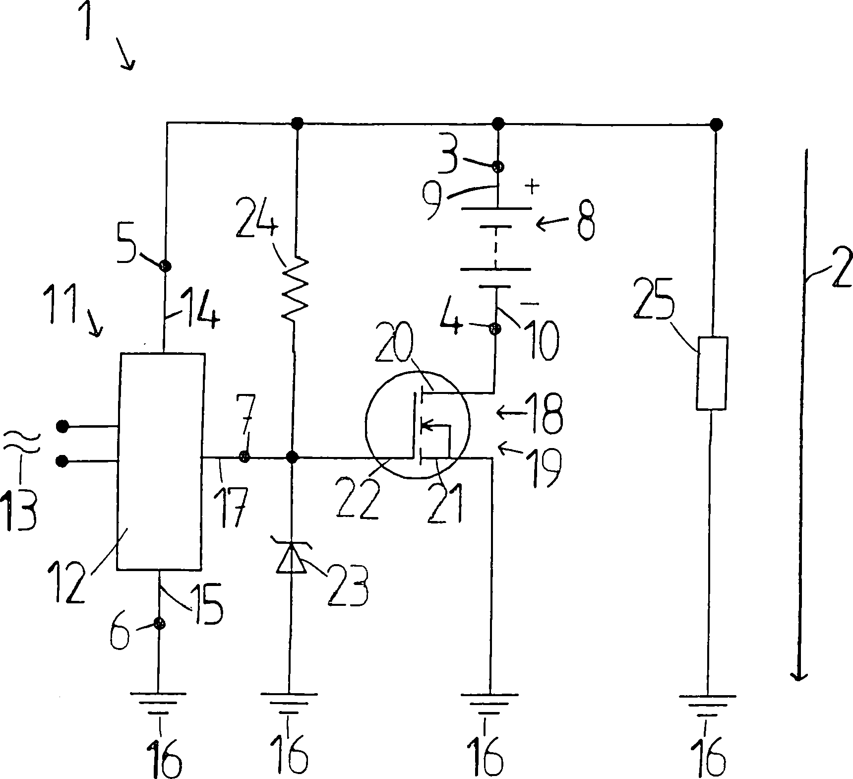
Die
einzige Figur zeigt schematisch eine Vorrichtung
An
der zweiten Anschlußanordnung
Die
Ausgangsspannung der zweiten Gleichspannungsquelle
Der
Feldeffekttransistor
Es
werden nun drei verschiedene Betriebsweisen der Vorrichtung
Eine
Last
Bei
der ersten Betriebsweise ist die erste Gleichspannungsquelle
Bei
der zweiten Betriebsweise ist die erste Gleichspannungsquelle
Bei
der dritten Betriebsweise der Vorrichtung
Insgesamt
verhindert der Feldeffekttransistor
Selbstverständlich ist
es auch möglich,
daß die
beschriebene Vorrichtung
Claims (16)
Priority Applications (8)
| Application Number | Priority Date | Filing Date | Title |
|---|---|---|---|
| DE102005011520A DE102005011520A1 (en) | 2005-03-10 | 2005-03-10 | Apparatus and method for providing a DC voltage |
| AT06706091T ATE456180T1 (en) | 2005-03-10 | 2006-03-01 | DEVICE AND METHOD FOR PROVIDING A DC VOLTAGE |
| PCT/DK2006/000120 WO2006094504A2 (en) | 2005-03-10 | 2006-03-01 | Device and method for supplying direct voltage |
| CN2006800078090A CN101138143B (en) | 2005-03-10 | 2006-03-01 | Apparatus and method for providing direct voltage |
| EP06706091A EP1856785B1 (en) | 2005-03-10 | 2006-03-01 | Device and method for supplying direct voltage |
| US11/817,902 US20080198522A1 (en) | 2005-03-10 | 2006-03-01 | Device and Method for Supplying Direct Voltage |
| DE502006005979T DE502006005979D1 (en) | 2005-03-10 | 2006-03-01 | DC VOLTAGE |
| IT000180A ITTO20060180A1 (en) | 2005-03-10 | 2006-03-09 | PROCEDURE FOR CONTROL OF A CONTINUOUS VOLTAGE SOURCE AND VOLTAGE FEEDER DEVICE |
Applications Claiming Priority (1)
| Application Number | Priority Date | Filing Date | Title |
|---|---|---|---|
| DE102005011520A DE102005011520A1 (en) | 2005-03-10 | 2005-03-10 | Apparatus and method for providing a DC voltage |
Publications (1)
| Publication Number | Publication Date |
|---|---|
| DE102005011520A1 true DE102005011520A1 (en) | 2006-10-05 |
Family
ID=36953724
Family Applications (2)
| Application Number | Title | Priority Date | Filing Date |
|---|---|---|---|
| DE102005011520A Withdrawn DE102005011520A1 (en) | 2005-03-10 | 2005-03-10 | Apparatus and method for providing a DC voltage |
| DE502006005979T Active DE502006005979D1 (en) | 2005-03-10 | 2006-03-01 | DC VOLTAGE |
Family Applications After (1)
| Application Number | Title | Priority Date | Filing Date |
|---|---|---|---|
| DE502006005979T Active DE502006005979D1 (en) | 2005-03-10 | 2006-03-01 | DC VOLTAGE |
Country Status (7)
| Country | Link |
|---|---|
| US (1) | US20080198522A1 (en) |
| EP (1) | EP1856785B1 (en) |
| CN (1) | CN101138143B (en) |
| AT (1) | ATE456180T1 (en) |
| DE (2) | DE102005011520A1 (en) |
| IT (1) | ITTO20060180A1 (en) |
| WO (1) | WO2006094504A2 (en) |
Families Citing this family (1)
| Publication number | Priority date | Publication date | Assignee | Title |
|---|---|---|---|---|
| DE102011121975A1 (en) * | 2010-12-30 | 2012-07-05 | Secop Gmbh | System and method for protecting an energy consuming circuit |
Citations (2)
| Publication number | Priority date | Publication date | Assignee | Title |
|---|---|---|---|---|
| US3636381A (en) * | 1971-02-16 | 1972-01-18 | Gte Sylvania Inc | Transistorized load control circuit comprising high- and low-parallel voltage sources |
| US5274272A (en) * | 1991-11-11 | 1993-12-28 | U.S. Philips Corporation | Device for supplying electrical energy to a load |
Family Cites Families (20)
| Publication number | Priority date | Publication date | Assignee | Title |
|---|---|---|---|---|
| US3321690A (en) * | 1964-10-19 | 1967-05-23 | Sonotone Corp | Rechargeable battery assembly with reverse polarity charge protection |
| US3976986A (en) * | 1973-09-27 | 1976-08-24 | Zabroski Stanley E | Emergency lamp and solid state switching circuit therefor |
| US4546302A (en) * | 1978-08-14 | 1985-10-08 | Century Mfg. Co. | Protective sensing means for battery charging circuit |
| US4292578A (en) * | 1979-08-13 | 1981-09-29 | The United States Of America As Represented By The United States Department Of Energy | Combination field chopper and battery charger |
| US4788450A (en) * | 1987-09-11 | 1988-11-29 | General Electric Company | Backup power switch |
| JP2776493B2 (en) * | 1994-08-12 | 1998-07-16 | インターナショナル・ビジネス・マシーンズ・コーポレイション | Power supply device for electronic equipment and control method thereof |
| CN1138768A (en) * | 1995-06-20 | 1996-12-25 | 明碁电脑股份有限公司 | battery charger |
| US5962936A (en) * | 1997-10-21 | 1999-10-05 | Twinhead International Corp. | Power supply device for LCD backlight converter |
| US6331763B1 (en) * | 1998-04-15 | 2001-12-18 | Tyco Electronics Corporation | Devices and methods for protection of rechargeable elements |
| US6122181A (en) * | 1998-05-21 | 2000-09-19 | Exide Electronics Corporation | Systems and methods for producing standby uninterruptible power for AC loads using rectified AC and battery |
| DE19842656A1 (en) * | 1998-09-17 | 2000-03-23 | Volkswagen Ag | Two-battery system |
| AT410382B (en) * | 2000-06-28 | 2003-04-25 | Fronius Schweissmasch Prod | Electronic circuit for fitting to a battery charging device connects an energy-supplying device to an energy source via terminals to convert energy from an AC voltage into a DC voltage and pass converted energy to a consumer. |
| JP2002112469A (en) * | 2000-09-29 | 2002-04-12 | Allied Tereshisu Kk | Or circuit consisting of field-effect transistors and power supply using it |
| US7671489B1 (en) * | 2001-01-26 | 2010-03-02 | Sirf Technology, Inc. | Method and apparatus for selectively maintaining circuit power when higher voltages are present |
| EP1360090B1 (en) | 2001-02-16 | 2005-01-12 | Siemens Aktiengesellschaft | Motor vehicle electric system |
| US6522190B1 (en) * | 2001-10-31 | 2003-02-18 | International Business Machines Corporation | High efficiency multiple input voltage sources power supply |
| FI118024B (en) * | 2001-12-17 | 2007-05-31 | Tellabs Oy | Polarity protection by MOSFET |
| US6969971B2 (en) * | 2002-12-05 | 2005-11-29 | International Rectifier Corporation | Reverse battery protection circuit |
| JP4690915B2 (en) * | 2006-03-10 | 2011-06-01 | 日立オートモティブシステムズ株式会社 | Integrated circuit power protection circuit |
| CA2653778C (en) * | 2006-06-01 | 2013-03-26 | Exaflop Llc | Data center uninterruptible power distribution architecture |
-
2005
- 2005-03-10 DE DE102005011520A patent/DE102005011520A1/en not_active Withdrawn
-
2006
- 2006-03-01 CN CN2006800078090A patent/CN101138143B/en active Active
- 2006-03-01 AT AT06706091T patent/ATE456180T1/en active
- 2006-03-01 US US11/817,902 patent/US20080198522A1/en not_active Abandoned
- 2006-03-01 DE DE502006005979T patent/DE502006005979D1/en active Active
- 2006-03-01 WO PCT/DK2006/000120 patent/WO2006094504A2/en not_active Ceased
- 2006-03-01 EP EP06706091A patent/EP1856785B1/en active Active
- 2006-03-09 IT IT000180A patent/ITTO20060180A1/en unknown
Patent Citations (2)
| Publication number | Priority date | Publication date | Assignee | Title |
|---|---|---|---|---|
| US3636381A (en) * | 1971-02-16 | 1972-01-18 | Gte Sylvania Inc | Transistorized load control circuit comprising high- and low-parallel voltage sources |
| US5274272A (en) * | 1991-11-11 | 1993-12-28 | U.S. Philips Corporation | Device for supplying electrical energy to a load |
Also Published As
| Publication number | Publication date |
|---|---|
| DE502006005979D1 (en) | 2010-03-11 |
| ATE456180T1 (en) | 2010-02-15 |
| WO2006094504A2 (en) | 2006-09-14 |
| EP1856785A2 (en) | 2007-11-21 |
| ITTO20060180A1 (en) | 2006-09-11 |
| CN101138143A (en) | 2008-03-05 |
| EP1856785B1 (en) | 2010-01-20 |
| US20080198522A1 (en) | 2008-08-21 |
| CN101138143B (en) | 2013-03-27 |
| WO2006094504A3 (en) | 2006-12-14 |
Similar Documents
| Publication | Publication Date | Title |
|---|---|---|
| DE19824283B4 (en) | Current control circuit | |
| DE3934577A1 (en) | POWER SUPPLY DEVICE WITH INRED CURRENT LIMITATION | |
| DE102017218952A1 (en) | SEMICONDUCTOR SWITCH CONTROL DEVICE | |
| DE10057259A1 (en) | Motor vehicle multiple voltage power supply, has a series connection of batteries and a switch arrangement that allows the voltage supply to be easily changed over | |
| WO2013087604A1 (en) | Circuit arrangement for detecting a short circuit in a power switch | |
| WO2020127414A1 (en) | Apparatus and method for the direction-dependent operation of an electrochemical energy store | |
| EP1299933B1 (en) | Electronic circuit for an energy supply device, especially for a charging device for batteries | |
| DE3741394C2 (en) | Circuit arrangement for protection against reverse polarity damage for load circuits with a MOS-FET as switching transistor | |
| DE102017202295A1 (en) | Circuit arrangement for carrying out a comparison | |
| WO2023011768A1 (en) | Circuit breaker unit | |
| DE3930896A1 (en) | Polarisation protective circuit for DC consumer - has inversely operated MOSFET between earth input and output | |
| EP3361596B1 (en) | Battery with a battery management system which comprises an electronic switching circuit | |
| DE19604041C1 (en) | High-side switch load current detection circuit | |
| EP1856785B1 (en) | Device and method for supplying direct voltage | |
| EP4226500B1 (en) | Power supply device and method for checking a field-effect transistor of such a power supply device | |
| DE3834867C1 (en) | Circuit arrangement for the parallel connection of power supply devices | |
| DE10253980B4 (en) | Device for limiting the inrush current | |
| DE4428115A1 (en) | Control unit with a circuit arrangement for protecting the control unit when the control unit mass is interrupted | |
| DE10349629B4 (en) | Electronic circuit | |
| DE102021214975A1 (en) | Circuit arrangement for checking the turn-off capability of an electronic switch | |
| DE10256473B4 (en) | Portable remote control unit | |
| DE3634070C2 (en) | ||
| DE102022214262B4 (en) | Securing device for securing an electronic high-voltage system, high-voltage system, electric axle drive and vehicle | |
| DE202017000743U1 (en) | Electronic switching device of a battery management system and battery | |
| DE102007053041A1 (en) | Circuit arrangement for control device, has two field effective transistors and zener-diode connected in series in anti-parallel manner, where zener-diode is connected directly between both field effective transistors |
Legal Events
| Date | Code | Title | Description |
|---|---|---|---|
| OP8 | Request for examination as to paragraph 44 patent law | ||
| 8127 | New person/name/address of the applicant |
Owner name: DANFOSS FLENSBURG GMBH, 24939 FLENSBURG, DE |
|
| R081 | Change of applicant/patentee |
Owner name: SECOP GMBH, DE Free format text: FORMER OWNER: DANFOSS COMPRESSORS GMBH, 24939 FLENSBURG, DE Effective date: 20110310 |
|
| R082 | Change of representative |
Representative=s name: PATENTANWAELTE KNOBLAUCH UND KNOBLAUCH, DE Representative=s name: PATENTANWAELTE KNOBLAUCH UND KNOBLAUCH, 60322 FRAN |
|
| R081 | Change of applicant/patentee |
Owner name: SECOP GMBH, DE Free format text: FORMER OWNER: DANFOSS FLENSBURG GMBH, 24939 FLENSBURG, DE Effective date: 20111227 Owner name: SECOP GMBH, DE Free format text: FORMER OWNER: DANFOSS HOUSEHOLD COMPRESSORS GMBH, 24939 FLENSBURG, DE Effective date: 20120209 |
|
| R082 | Change of representative |
Representative=s name: PATENTANWAELTE KNOBLAUCH UND KNOBLAUCH, DE Effective date: 20111227 Representative=s name: PATENTANWAELTE KNOBLAUCH UND KNOBLAUCH, DE Effective date: 20120209 |
|
| R119 | Application deemed withdrawn, or ip right lapsed, due to non-payment of renewal fee |
Effective date: 20131001 |