[go: up one dir, main page]

DE102004063415A1 - Rotation angle detection device and torque detection device - Google Patents

Rotation angle detection device and torque detection device Download PDF

Info

Publication number
DE102004063415A1
DE102004063415A1 DE102004063415A DE102004063415A DE102004063415A1 DE 102004063415 A1 DE102004063415 A1 DE 102004063415A1 DE 102004063415 A DE102004063415 A DE 102004063415A DE 102004063415 A DE102004063415 A DE 102004063415A DE 102004063415 A1 DE102004063415 A1 DE 102004063415A1
Authority
DE
Germany
Prior art keywords
detection
detection signals
angle
phase angle
marks
Prior art date
Legal status (The legal status is an assumption and is not a legal conclusion. Google has not performed a legal analysis and makes no representation as to the accuracy of the status listed.)
Withdrawn
Application number
DE102004063415A
Other languages
German (de)
Inventor
Yoshitomo Tokumoto
Current Assignee (The listed assignees may be inaccurate. Google has not performed a legal analysis and makes no representation or warranty as to the accuracy of the list.)
JTEKT Corp
Original Assignee
Koyo Seiko Co Ltd
Priority date (The priority date is an assumption and is not a legal conclusion. Google has not performed a legal analysis and makes no representation as to the accuracy of the date listed.)
Filing date
Publication date
Application filed by Koyo Seiko Co Ltd filed Critical Koyo Seiko Co Ltd
Publication of DE102004063415A1 publication Critical patent/DE102004063415A1/en
Withdrawn legal-status Critical Current

Links

Classifications

    • GPHYSICS
    • G01MEASURING; TESTING
    • G01LMEASURING FORCE, STRESS, TORQUE, WORK, MECHANICAL POWER, MECHANICAL EFFICIENCY, OR FLUID PRESSURE
    • G01L3/00Measuring torque, work, mechanical power, or mechanical efficiency, in general
    • G01L3/02Rotary-transmission dynamometers
    • G01L3/04Rotary-transmission dynamometers wherein the torque-transmitting element comprises a torsionally-flexible shaft
    • G01L3/10Rotary-transmission dynamometers wherein the torque-transmitting element comprises a torsionally-flexible shaft involving electric or magnetic means for indicating
    • G01L3/109Rotary-transmission dynamometers wherein the torque-transmitting element comprises a torsionally-flexible shaft involving electric or magnetic means for indicating involving measuring phase difference of two signals or pulse trains
    • BPERFORMING OPERATIONS; TRANSPORTING
    • B62LAND VEHICLES FOR TRAVELLING OTHERWISE THAN ON RAILS
    • B62DMOTOR VEHICLES; TRAILERS
    • B62D15/00Steering not otherwise provided for
    • B62D15/02Steering position indicators ; Steering position determination; Steering aids
    • B62D15/021Determination of steering angle
    • B62D15/0215Determination of steering angle by measuring on the steering column
    • BPERFORMING OPERATIONS; TRANSPORTING
    • B62LAND VEHICLES FOR TRAVELLING OTHERWISE THAN ON RAILS
    • B62DMOTOR VEHICLES; TRAILERS
    • B62D6/00Arrangements for automatically controlling steering depending on driving conditions sensed and responded to, e.g. control circuits
    • B62D6/08Arrangements for automatically controlling steering depending on driving conditions sensed and responded to, e.g. control circuits responsive only to driver input torque
    • B62D6/10Arrangements for automatically controlling steering depending on driving conditions sensed and responded to, e.g. control circuits responsive only to driver input torque characterised by means for sensing or determining torque
    • GPHYSICS
    • G01MEASURING; TESTING
    • G01DMEASURING NOT SPECIALLY ADAPTED FOR A SPECIFIC VARIABLE; ARRANGEMENTS FOR MEASURING TWO OR MORE VARIABLES NOT COVERED IN A SINGLE OTHER SUBCLASS; TARIFF METERING APPARATUS; MEASURING OR TESTING NOT OTHERWISE PROVIDED FOR
    • G01D5/00Mechanical means for transferring the output of a sensing member; Means for converting the output of a sensing member to another variable where the form or nature of the sensing member does not constrain the means for converting; Transducers not specially adapted for a specific variable
    • G01D5/12Mechanical means for transferring the output of a sensing member; Means for converting the output of a sensing member to another variable where the form or nature of the sensing member does not constrain the means for converting; Transducers not specially adapted for a specific variable using electric or magnetic means
    • G01D5/244Mechanical means for transferring the output of a sensing member; Means for converting the output of a sensing member to another variable where the form or nature of the sensing member does not constrain the means for converting; Transducers not specially adapted for a specific variable using electric or magnetic means influencing characteristics of pulses or pulse trains; generating pulses or pulse trains
    • G01D5/24409Interpolation using memories
    • GPHYSICS
    • G01MEASURING; TESTING
    • G01DMEASURING NOT SPECIALLY ADAPTED FOR A SPECIFIC VARIABLE; ARRANGEMENTS FOR MEASURING TWO OR MORE VARIABLES NOT COVERED IN A SINGLE OTHER SUBCLASS; TARIFF METERING APPARATUS; MEASURING OR TESTING NOT OTHERWISE PROVIDED FOR
    • G01D5/00Mechanical means for transferring the output of a sensing member; Means for converting the output of a sensing member to another variable where the form or nature of the sensing member does not constrain the means for converting; Transducers not specially adapted for a specific variable
    • G01D5/12Mechanical means for transferring the output of a sensing member; Means for converting the output of a sensing member to another variable where the form or nature of the sensing member does not constrain the means for converting; Transducers not specially adapted for a specific variable using electric or magnetic means
    • G01D5/244Mechanical means for transferring the output of a sensing member; Means for converting the output of a sensing member to another variable where the form or nature of the sensing member does not constrain the means for converting; Transducers not specially adapted for a specific variable using electric or magnetic means influencing characteristics of pulses or pulse trains; generating pulses or pulse trains
    • G01D5/24457Failure detection
    • GPHYSICS
    • G01MEASURING; TESTING
    • G01DMEASURING NOT SPECIALLY ADAPTED FOR A SPECIFIC VARIABLE; ARRANGEMENTS FOR MEASURING TWO OR MORE VARIABLES NOT COVERED IN A SINGLE OTHER SUBCLASS; TARIFF METERING APPARATUS; MEASURING OR TESTING NOT OTHERWISE PROVIDED FOR
    • G01D5/00Mechanical means for transferring the output of a sensing member; Means for converting the output of a sensing member to another variable where the form or nature of the sensing member does not constrain the means for converting; Transducers not specially adapted for a specific variable
    • G01D5/12Mechanical means for transferring the output of a sensing member; Means for converting the output of a sensing member to another variable where the form or nature of the sensing member does not constrain the means for converting; Transducers not specially adapted for a specific variable using electric or magnetic means
    • G01D5/244Mechanical means for transferring the output of a sensing member; Means for converting the output of a sensing member to another variable where the form or nature of the sensing member does not constrain the means for converting; Transducers not specially adapted for a specific variable using electric or magnetic means influencing characteristics of pulses or pulse trains; generating pulses or pulse trains
    • G01D5/24471Error correction
    • G01D5/2449Error correction using hard-stored calibration data
    • GPHYSICS
    • G01MEASURING; TESTING
    • G01LMEASURING FORCE, STRESS, TORQUE, WORK, MECHANICAL POWER, MECHANICAL EFFICIENCY, OR FLUID PRESSURE
    • G01L3/00Measuring torque, work, mechanical power, or mechanical efficiency, in general
    • G01L3/02Rotary-transmission dynamometers
    • G01L3/04Rotary-transmission dynamometers wherein the torque-transmitting element comprises a torsionally-flexible shaft
    • G01L3/10Rotary-transmission dynamometers wherein the torque-transmitting element comprises a torsionally-flexible shaft involving electric or magnetic means for indicating
    • G01L3/101Rotary-transmission dynamometers wherein the torque-transmitting element comprises a torsionally-flexible shaft involving electric or magnetic means for indicating involving magnetic or electromagnetic means
    • G01L3/104Rotary-transmission dynamometers wherein the torque-transmitting element comprises a torsionally-flexible shaft involving electric or magnetic means for indicating involving magnetic or electromagnetic means involving permanent magnets

Landscapes

  • Physics & Mathematics (AREA)
  • General Physics & Mathematics (AREA)
  • Engineering & Computer Science (AREA)
  • Chemical & Material Sciences (AREA)
  • Combustion & Propulsion (AREA)
  • Transportation (AREA)
  • Mechanical Engineering (AREA)
  • Electromagnetism (AREA)
  • Measurement Of Length, Angles, Or The Like Using Electric Or Magnetic Means (AREA)
  • Power Steering Mechanism (AREA)
  • Transmission And Conversion Of Sensor Element Output (AREA)

Abstract

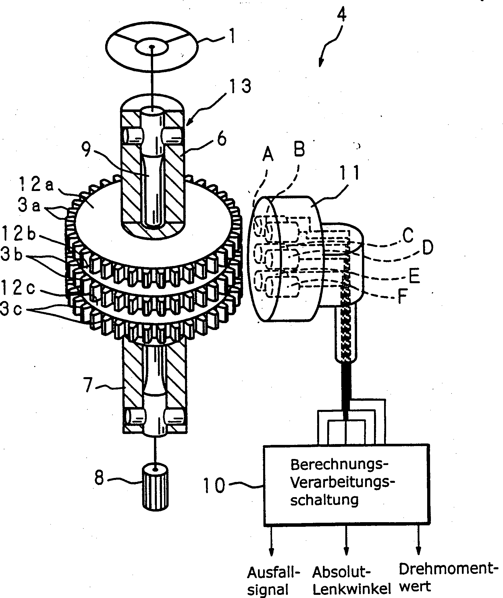
Bei einer Drehwinkeldetektionsvorrichtung sind erste Markierungen (3b) und zweite Markierungen (3c), deren Anzahlen einander teilerfremd sind, an den Rotoren vorgesehen, die sich koaxial miteinander drehen. Der Drehwinkel des Rotors wird detektiert auf der Basis der Detektionssignale von jedem zweier Sensoren (A, B), die den betreffenden Markierungen (3b, 3c) gegenüberliegend angeordnet sind, wobei diese ausgegebenen Detektionssignale während der Drehung des Rotors unterschiedliche Phasen aufweisen. Der Phasenwinkelbereich wird basierend auf dem Größenverhältnis zwischen dem einen Detektionssignal und dem anderen Detektionssignal der beiden Sensoren bestimmt. Die Beziehung zwischen dem Detektionssignal und einem Phasenwinkel ist vorgespeichert. Auf der Basis des bestimmten Phasenwinkels und unter Bezugnahme auf diese Beziehung wird der Phasenwinkel des anderen Detektionssignals errechnet; auf diese Weise wird der Drehwinkel des Rotors detektiert.at a rotation angle detection device are first markers (3b) and second marks (3c) whose numbers are relatively alien to each other are provided on the rotors that rotate coaxially with each other. The rotational angle of the rotor is detected on the basis of the detection signals from each of two sensors (A, B) showing the markings concerned (3b, 3c) opposite are arranged, these output detection signals during the Rotation of the rotor have different phases. The phase angle range becomes based on the size ratio between one detection signal and the other detection signal the determined by both sensors. The relationship between the detection signal and a phase angle is pre-stored. On the basis of the particular Phase angle and with reference to this relationship is the Calculated phase angle of the other detection signal; to this Way, the rotation angle of the rotor is detected.

Figure 00000001
Figure 00000001

Description

Die vorliegende Erfindung betrifft eine Drehwinkel-Detektionsvorrichtung und eine Drehmoment-Detektionsvorrichtung mit einem oder mehreren an einem Rotor vorgesehenen Markierungen und mehreren gegenüber den Markierungen angeordneten Detektionseinrichtungen zum Ausgeben von Detektionssignalen mit Phasen, die entsprechend jeder Position der Markierungen beim Drehen des Rotors voneinander abweichen.The The present invention relates to a rotation angle detecting device and a torque detection device having one or more provided on a rotor markings and several opposite to the Markers arranged detection means for outputting Detection signals with phases corresponding to each position of the Markings differ when turning the rotor.

Als Lenkvorrichtung für Kraftfahrzeuge ist eine elektrische Servolenkvorrichtung, die einen Elektromotor zwecks Lenkunterstützung und Verringerung der von dem Fahrer aufzubringenden Last antreibt, bekannt. Solche elektrische Servolenkvorrichtungen weisen eine mit einem Lenkelement (Lenkrad) verbundene Antriebswelle, eine über eine Zahnstange o.ä. mit lenkbaren Rädern verbundene Abtriebswelle und eine Verbindungswelle auf, welche die Antriebswelle mit der Abtriebswelle verbindet. Anhand des Torsionswinkels, der an der Verbindungswelle erzeugt wird, detektiert der Drehmomentsensor das auf die Antriebswelle aufgebrachte Lenk-Drehmoment. Anhand des von dem Drehmomentsensor detektierten Lenk-Drehmoments wird der Antrieb durch den für die Lenkunterstützung vorgesehenen Elektromotor, der mit der Abtriebswelle verbunden ist, gesteuert. Der Anmelder der vorliegenden Anmeldung hat bereits eine Drehwinkel-Detektionsvorrichtung und eine Drehmoment-Detektionsvorrichtung für eine Kraftfahrzeug-Lenkvorrichtung vorgeschlagen (Japanische Offenlegungsschrift Nr. 2003-83823).When Steering device for Motor vehicles is an electric power steering device that has an electric motor for the purpose of steering assistance and reducing the load to be applied by the driver, known. Such electric power steering devices have a a drive element (steering wheel) connected drive shaft, one via a rack etc. With steerable wheels connected output shaft and a connecting shaft, which the Drive shaft connects to the output shaft. Based on the torsion angle, generated at the connection shaft, the torque sensor detects on the drive shaft applied steering torque. Based on the of the torque sensor detected steering torque is the drive through the for the steering assistance provided electric motor which is connected to the output shaft, controlled. The applicant of the present application already has a A rotation angle detecting device and a torque detecting device for a motor vehicle steering device (Japanese Patent Laid-Open Publication No. 2003-83823).

Ferner hat der Anmelder eine Drehwinkel-Detektionsvorrichtung und eine Drehmoment-Detektionsvorrichtung vorgeschlagen, die mit der Drehwinkel-Detektionsvorrichtung (Drehmomentsensor) versehen ist, (Japanische Offenlegungsschrift Nr. 2003-344188). Die Drehwinkel-Detektionsvorrichtung weist zwei Detektionseinrichtungen auf, die jeweils gegenüber an einem Rotor vorgesehenen ersten Markierungen und an dem Rotor vorgesehenen zweiten Markierungen angeordnet sind, wobei die Anzahl der zweiten Markierungen zu der Anzahl der ersten Markierungen teilerfremd ist. Die beiden Detektionseinrichtungen geben Detektionssignale mit Phasen aus, die sich beim Drehen des Rotors voneinander unterscheiden. Die Drehwinkel-Detektionsvorrichtung umfasst ferner eine Berechnungseinrichtung zum Ausführen einer vorbestimmten Berechnung unter Verwendung der Detektionssignale, die jeweils von den beiden Detektionseinrichtungen ausgegeben worden sind, und eine Speichereinrichtung zum Speichern der Beziehung zwischen dem Ergebnis einer von der Berechnungseinrichtung im voraus durchgeführten Berechnung und den Phasenwinkeln der Detektionssignale, wobei anhand des Ergebnisses der von der Berechnungseinrichtung ausgeführten Berechnung und durch Bezugnahme auf die Speichereinrichtung ein Phasenwinkel der Detektionssignale errechnet wird und anhand des erhaltenen Phasenwinkels der Drehwinkel des Rotors detektiert wird.Further the applicant has a rotation angle detection device and a Torque detection device proposed with the rotation angle detection device (Torque sensor) is provided, (Japanese Patent Laid-open No. 2003-344188). The rotation angle detection device has two Detection devices, each provided opposite to a rotor first marks and provided on the rotor second marks are arranged, wherein the number of second marks to the Number of first marks is prime. The two detection devices Output detection signals with phases that appear when turning the Rotor differ from each other. The rotation angle detection device further comprises a calculator for performing a predetermined calculation using the detection signals respectively from the two Detection devices have been issued, and a memory device for Storing the relationship between the result of one of the calculating means done in advance Calculation and the phase angles of the detection signals, using the result of the calculation performed by the calculating means and by referring to the memory device, a phase angle the detection signals is calculated and based on the phase angle obtained the angle of rotation of the rotor is detected.

Bei der beispielsweise in der oben genannten Japanischen Offenlegungsschrift Nr. 2003-344188 beschriebenen Drehwinkel-Detektionsvorrichtung und Drehmoment-Detektionsvorrichtung bildet eines der Detektionssignale ungefähr eine Sinuswelle und ist die Phasendifferenz auf 90° eingestellt (entsprechend bildet das andere Detektionssignal ungefähr eine Kosinuswelle), wobei der Drehwinkel θ aus θ = tan–1θ = tan–1 (sinθ/cosθ) errechnet wird. Die Detektionssignale enthalten jedoch Fehler, wie z.B. Welligkeiten. Wenn die Berechnung, wie z.B. sinθ/cosθ, unter Verwendung der Fehler enthaltenden Detektionssignale ausgeführt wird, werden die in dem Berechnungsergebnis enthaltenen Fehler größer als die ursprünglichen Fehler. Daher besteht das Problem, dass es kaum möglich ist, einen präzisen Drehwinkel zu erhalten.In the rotation angle detection apparatus and the torque detection apparatus described in, for example, Japanese Patent Laid-Open Publication No. 2003-344188, one of the detection signals constitutes approximately a sine wave and the phase difference is set at 90 ° (corresponding to the other detection signal is approximately one cosine wave) Rotation angle θ from θ = tan -1 θ = tan -1 (sinθ / cosθ) is calculated. However, the detection signals contain errors such as ripples. When the calculation such as sinθ / cosθ is carried out using the detection signals including errors, the errors included in the calculation result become larger than the original errors. Therefore, there is a problem that it is hardly possible to obtain a precise rotation angle.

Der Erfindung liegt die Aufgabe zugrunde, eine Drehwinkel-Detektionsvorrichtung bereitzustellen, die in der Lage ist, einen präzisen Drehwinkel zu liefern.Of the Invention is based on the object, a rotation angle detection device capable of providing a precise angle of rotation.

Der vorliegenden Erfindung liegt ferner die Aufgabe zugrunde, eine Drehmoment-Detektionsvorrichtung bereitzustellen, die in der Lage ist, einen Drehmomentwert präzise zu detektieren.Of the The present invention is further based on the object, a torque detection device which is capable of precisely setting a torque value detect.

Die Lösung dieser Aufgaben erfolgt erfindungsgemäß mit den Merkmalen des Patentanspruchs 1 bzw. 4.The solution These objects are achieved according to the invention with the features of the claim 1 or 4.

Da eine Berechnung, deren Ergebnis einen großen Fehler enthält, nicht durchgeführt wird, wird erfindungsgemäß eine Drehwinkel-Detektionsvorrichtung bereitgestellt, die in der Lage ist, einen präzisen Drehwinkel zu liefern.There a calculation whose result contains a large error is not carried out is, according to the invention, a rotation angle detection device provided that is able to provide a precise angle of rotation.

Da eine Berechnung, deren Ergebnis einen großen Fehler enthält, nicht durchgeführt wird, wird erfindungsgemäß eine Drehmoment-Detektionsvorrichtung vorgeschlagen, die in der Lage ist, einen präzisen Drehmomentwert zu liefern.There a calculation whose result contains a large error is not carried out is, according to the invention, a torque-detecting device proposed, which is able to provide a precise torque value.

Die oben genannten und weitere Aufgaben und Merkmale der Erfindung werden anhand der folgenden detaillierten Beschreibung mit Bezug auf die beiliegenden Zeichnungen offensichtlich.The above and other objects and features of the invention will become more apparent from the following detailed description with reference to FIGS accompanying drawings.

Es zeigen:It demonstrate:

1 eine schematische Darstellung des Aufbaus einer Drehwinkel-Detektionsvorrichtung und einer Drehmoment-Detektionsvorrichtung gemäß einer Ausführungsform der vorliegenden Erfindung; 1 a schematic representation of the structure of a rotation angle detection device and a torque detection device according to an embodiment of the present invention;

2 ein Blockschaltbild mit Darstellung eines Beispiels für die interne Konfiguration einer Berechnungs-Verarbeitungsschaltung; 2 a block diagram showing an example of the internal configuration of a calculation processing circuit;

3A3C Diagramme mit Darstellung eines Beispiels für die Wellenform von von magnetometrischen Sensoren detektierten Detektionssignalen; 3A - 3C Diagrams showing an example of the waveform of detection signals detected by magnetometric sensors;

4 ein Diagramm mit Darstellung eines Beispiels für die Wellenform durch magnetometrische Sensoren detektierter Detektionssignale, wobei die Anzahl von einander gegenüberliegenden Markierungen unterschiedlich ist; 4 a diagram showing an example of the waveform by magnetometric sensors detected detection signals, wherein the number of opposing markers is different;

5 ein Ablaufdiagramm mit Darstellung eines Beispiels für die Arbeitsweise einer Berechnungs-Verarbeitungsschaltung; 5 a flow chart showing an example of the operation of a calculation processing circuit;

6 ein Diagramm mit Darstellung des Inhalts einer Tabelle, in der ein Beispiel für die Beziehung zwischen korrigierten Detektionssignalen, die im voraus gemessen worden sind, und einem Phasenwinkel gespeichert ist; 6 a diagram showing the content of a table, in which an example of the relationship between corrected detection signals that have been measured in advance, and a phase angle is stored;

7 ein Ablaufdiagramm mit Darstellung eines Beispiels für die Arbeitsweise der Berechnungs-Verarbeitungsschaltung; 7 a flowchart showing an example of the operation of the calculation processing circuit;

8 Diagramme mit Darstellung eines Beispiels für die Arbeitsweise eines Lenkwinkel-Berechnungsteils; 8th Diagrams showing an example of the operation of a steering angle calculation part;

9 ein Diagramm mit Darstellung eines Beispiels für die Arbeitsweise eines Drehmoment-Berechnungsteils; 9 a diagram showing an example of the operation of a torque calculation part;

10 ein Diagramm mit Darstellung eines Beispiels für einen von dem Drehmoment-Berechnungsteil ausgegebenen Drehmomentwert; 10 FIG. 14 is a diagram showing an example of a torque value output from the torque calculating part; FIG.

11 ein Ablaufdiagramm mit Darstellung eines Beispiels für die Arbeitsweise der Berechnungs-Verarbeitungsschaltung; und 11 a flowchart showing an example of the operation of the calculation processing circuit; and

12 ein Diagramm mit Darstellung eines Beispiels für einen von dem Absolut-Lenkwinkel-Berechnungsteil ausgegebenen absoluten Lenkwinkel. 12 FIG. 12 is a diagram showing an example of an absolute steering angle output from the absolute steering angle calculating part. FIG.

Nachstehend wird anhand der Zeichnungen, in denen Ausführungsformen gezeigt sind, die vorliegende Erfindung genauer erläutert.below is based on the drawings, in which embodiments are shown the present invention explained in more detail.

1 zeigt eine schematische Darstellung des Aufbaus einer Drehwinkel-Detektionsvorrichtung und einer Drehmoment-Detektionsvorrichtung gemäß einer Ausführungsform der vorliegenden Erfindung. Die Drehwinkel-Detektionsvorrichtung und der Drehmomentsensor 4 (die Drehmoment-Detektionsvorrichtung) umfassen eine Antriebswelle 6 (Rotor, erste Welle), deren oberes Ende mit einem Lenkelement 1 (Lenkrad) verbunden ist, und eine Abtriebswelle 7 (Rotor, zweite Welle), deren unteres Ende mit einem Ritzel 8 eines Lenkmechanismus verbunden ist. Die Antriebswelle 6 und die Abtriebswelle 7 sind koaxial miteinander verbunden, wobei eine Torsionsstange 8 (Verbindungswelle) mit kleinerem Durchmesser dazwischengeschaltet ist. Dies ist die Struktur einer Lenkwelle 13, die das Lenkelement 1 mit dem Lenkmechanismus verbindet. Die Umgebung des Verbindungsteils zwischen der Antriebswelle 6 und der Abtriebswelle 7 ist so strukturiert wie nachstehend beschrieben. 1 shows a schematic representation of the structure of a rotation angle detecting device and a torque detecting device according to an embodiment of the present invention. The rotation angle detection device and the torque sensor 4 (The torque detecting device) include a drive shaft 6 (Rotor, first shaft), whose upper end with a steering element 1 (Steering wheel) is connected, and an output shaft 7 (Rotor, second shaft), whose lower end with a pinion 8th a steering mechanism is connected. The drive shaft 6 and the output shaft 7 are coaxially connected to each other, with a torsion bar 8th (Connecting shaft) is interposed with a smaller diameter. This is the structure of a steering shaft 13 that the steering element 1 connects with the steering mechanism. The environment of the connecting part between the drive shaft 6 and the output shaft 7 is structured as described below.

Nahe dem Außenende des Verbindungsteils zwischen der Antriebswelle 6 und der Abtriebswelle 7 und koaxial zu der Antriebswelle 6 an deren Außenseite ist eine Markierungs-Platte 12a in Form einer Scheibe vorgesehen. An der Umfangsfläche der Markierungs-Platte 12a sind mehrere vorstehende Markierungen 3a aus Magnetmaterial ausgebildet; d.h. es sind beispielsweise 37 Vorsprünge vorgesehen, die in regelmäßigen Abständen in Umfangsrichtung vorstehend angeordnet sind. Die Markierung 3a bildet zahlreiche Zähne eines Stirnrads. Die Stirnräder in Form eines Rings bilden die Markierungs-Platte 12a mit den Markierungen 3a.Near the outer end of the connecting part between the drive shaft 6 and the output shaft 7 and coaxial with the drive shaft 6 on the outside of which is a marking plate 12a provided in the form of a disc. On the peripheral surface of the marking plate 12a are several prominent marks 3a formed of magnetic material; ie, for example 37 Projections provided which are arranged at regular intervals in the circumferential direction protruding. The mark 3a forms numerous teeth of a spur gear. The spur gears in the form of a ring form the marking plate 12a with the marks 3a ,

Nahe dem Außenende des Verbindungsteils zwischen der Antriebswelle 6 und der Abtriebswelle 7 und koaxial zu der Abtriebswelle 7 an deren Außenseite sind Markierungs-Platten 12b und 12c (Rotoren) jeweils in Form von Scheiben vorgesehen, wobei sich die Markierungs-Platte 12b auf der Seite der Antriebswelle 6 befindet. An der Umfangsfläche der Markierungs-Platte 12b sind mehrere vorstehende Markierungen 3b aus Magnetmaterial ausgebildet; d.h. es sind 37 Vorsprünge, bei denen es sich um die gleichen wie bei den Markierungen 3a handelt, in gleichen Abständen in Umfangsrichtung angeordnet und mit den Markierungen 3a ausgerichtet. An der Umfangsfläche der Markierungs-Platte 12c sind Vorsprünge aus einem Magnetmaterial ausgebildet; die Anzahl von Markierungen 3c ist zu der Anzahl von Markierungen 3b, bei denen es sich beispielsweise um 36 Vorsprünge handelt, die in gleichen Abständen in Umfangsrichtung vorstehend angeordnet sind, teilerfremd. Hier bezieht sich der Ausdruck "Anzahl, die zu einer anderen Anzahl teilerfremd ist" auf eine Anzahl, die mit einer anderen Anzahl keinen anderen gemeinsamen Nenner als 1 hat. Die Markierungen 3b und 3c bilden Zähne von Stirnrädern. Die Stirnräder in Form eines Rings bilden die Markierungs-Platten 12b, 12c mit den Markierungen 3b, 3c.Near the outer end of the connecting part between the drive shaft 6 and the output shaft 7 and coaxial with the output shaft 7 on the outside of which are marking plates 12b and 12c (Rotors) each provided in the form of discs, wherein the marking plate 12b on the side of the drive shaft 6 located. On the peripheral surface of the marking plate 12b are several prominent marks 3b formed of magnetic material; ie, there are 37 protrusions, which are the same as the markers 3a is arranged at equal intervals in the circumferential direction and with the markings 3a aligned. On the peripheral surface of the marking plate 12c projections are formed of a magnetic material; the number of marks 3c is to the number of marks 3b , which are, for example, 36 projections which are arranged at equal intervals in the circumferential direction above, alien. Here, the term "number that is prime to another number" refers to a number that has no other common denominator than 1 with another number. The marks 3b and 3c form teeth of spur gears. The spur gears in the form of a ring form the marking plates 12b . 12c with the marks 3b . 3c ,

An der Außenseite der Markierungs-Platten 12a, 12b und 12c ist ein Sensorkasten 11 angeordnet, der dem Außenrand der Markierungen 3a, 3b und 3c am Umfang der Platten zugewandt ist. Der Sensorkasten 11 ist an einem unbeweglichen Teil, wie z.B. einem (nicht gezeigten) Gehäuse, befestigt und wird von diesem getragen, wobei das unbewegliche Teil die Antriebswelle 6 und die Abtriebswelle 7 aufnimmt und trägt. In dem Sensorkasten 11 sind magnetometrische Sensoren A und B (Detektionseinrichtung), die in Umfangsrichtung jeweils unterschiedlichen Teilbereichen der auf der Seite der Antriebswelle 6 befindlichen Markierung 3a zugewandt sind, und magnetometrische Sensoren C und D (Detektionseinrichtung), die in Umfangsrichtung unterschiedlichen Teilbereichen der auf der Seite der Abtriebswelle 7 befindlichen Markierung 3b zugewandt sind, derart aufgenommen, dass ihre Positionen in Umfangsrichtung korrekt miteinander ausgerichtet sind. Ferner sind magnetometrische Sensoren E und F (Detektionseinrichtung) aufge nommen, die in Umfangsrichtung unterschiedlichen Teilbereichen der auf der Seite der Abtriebswelle 7 befindlichen Markierungen 3c zugewandt sind.On the outside of the marking plates 12a . 12b and 12c is a sensor box 11 arranged on the outer edge of the markings 3a . 3b and 3c facing the periphery of the plates. The sensor box 11 is fixed to and supported by an immovable part, such as a housing (not shown), the stationary part being the drive shaft 6 and the output shaft 7 absorbs and carries. In the sensor box 11 are magnetometric sensors A and B (detection device), which in the circumferential direction in each case different subregions of the on the side of the drive shaft 6 located mark 3a facing and magnetometric sensors C and D (detection device), the circumferentially different portions of the on the side of the output shaft 7 located mark 3b are facing, received in such a way that their positions are aligned correctly in the circumferential direction with each other. Furthermore, magnetometric sensors E and F (detection device) are taken, the circumferentially different portions of the on the side of the output shaft 7 located markings 3c are facing.

Die magnetometrischen Sensoren A, B, C, D, E und F sind Sensoren, die aus einem Element, wie z.B. einem Magnetowiderstandseffekt-Element (MR-Element) o.ä., gebildet sind, bei dem sich die elektrische Charakteristik (Widerstand) durch den Einfluss des Magnetfelds verändert, wobei sich das Detektionssignal entsprechend einer Veränderung eines benachbarten Teilbereichs der Markierung 3a, 3b oder 3c, der dem magnetometrischen Sensor gegenüberliegt, verändert. Diese Detektionssignale werden einer Berechnungs-Verarbeitungsschaltung 10 zugeführt, die einen außerhalb oder innerhalb des Sensorkastens 11 angeordneten Mikroprozessor aufweist.The magnetometric sensors A, B, C, D, E, and F are sensors formed of an element such as a magnetoresistance effect (MR) element or the like, which has an electrical characteristic (resistance). changed by the influence of the magnetic field, wherein the detection signal corresponding to a change of an adjacent portion of the marker 3a . 3b or 3c which opposes the magnetometric sensor changes. These detection signals become a calculation processing circuit 10 fed, one outside or inside the sensor box 11 arranged microprocessor.

2 zeigt ein Blockschaltbild mit Darstellung eines Beispiels für die interne Konfiguration der Berechnungs-Verarbeitungsschaltung 10. Die Berechnungs-Verarbeitungsschaltung 10 umfasst einen A/D-Konvertierteil 10a, der eine Analog/Digital-Konvertierung der Detektionssignale VA, VB, VC, VD, VE bzw. VF durchführt, die von den magnetometrischen Sensoren A, B, C, D, E, und F ausgegeben werden, und einen Sensorausgangssignal-Korrekturteil 10b, der die Detektionssignale VA, VB, VC, VD, VE und VF nach der Analog/Digital-Konvertierung korrigiert und die korrigierten Detektionssignale VA', VB', VC', VD', VE' und VF' ausgibt. 2 Fig. 10 is a block diagram showing an example of the internal configuration of the calculation processing circuit 10 , The calculation processing circuit 10 includes an A / D conversion part 10a performing analog-to-digital conversion of the detection signals V A , V B , V C , V D , V E, and V F , respectively, output from the magnetometric sensors A, B, C, D, E, and F, and a sensor output correction part 10b which corrects the detection signals V A , V B , V C , V D , V E and V F after the analog-to-digital conversion and the corrected detection signals V A ', V B ', V C ', V D ', V E 'and V F ' outputs.

Die Berechnungs-Verarbeitungsschaltung 10 umfasst ferner einen Lenkwinkel-Berechnungsteil 10c mit einer Tabelle (Speichereinrichtung), in der die Beziehung zwischen den korrigierten Detektionssignalen VA' und VB', die tatsächlich im voraus vor dem Versand ab Werk gemessen werden, und dem Phasenwinkel gespeichert ist; eine Tabelle (Speichereinrichtung), in der die Beziehung zwischen den korrigierten Detektionssignalen VC' und VD' und dem Phasenwinkel gespeichert ist; und eine Tabelle (Speichereinrichtung), in der die Beziehung zwischen den korrigierten Detektionssignalen VE' und VF' und dem Phasenwinkel gespeichert ist, und gibt Phasenwinkel θAB, θCD und θEF der Antriebswelle 6 und der Abtriebswelle 7 auf der Basis der korrigierten Signale VA', VB', VC', VD', VE' und VF' aus.The calculation processing circuit 10 further includes a steering angle calculating part 10c a table (memory means) in which the relationship between the corrected detection signals V A 'and V B ' which are actually measured in advance before shipment from the factory and the phase angle is stored; a table (memory means) in which the relationship between the corrected detection signals V C 'and V D ' and the phase angle is stored; and a table (memory means) in which the relationship between the corrected detection signals V E 'and V F ' and the phase angle is stored, and outputs phase angles θ AB , θ CD and θ EF of the drive shaft 6 and the output shaft 7 based on the corrected signals V A ', V B ', V C ', V D ', V E 'and V F ' off.

Ferner umfasst die Berechnungs-Verarbeitungsschaltung 10 einen Drehmoment-Berechnungsteil 10d, der den Drehmomentwert zwischen der Antriebswelle 6 und der Abtriebswelle 7 anhand der Phasenwinkel θAB und θCD berechnet und ausgibt, einen Absolut-Lenkwinkel-Berechnungsteil 10e, der eine Tabelle 14 zum Speichern der absoluten Lenkwinkel bei Drehung der Abtriebswelle 7 und zum Speichern der Phasenwinkel θCD und θEF (Phasenwinkel der Markierungen 3b und 3c), während diese miteinander verbunden sind, aufweist und den absoluten Lenkwinkel der Abtriebswelle 7 anhand der Phasenwinkel θCD und θEF berechnet und ausgibt, und einen Ausfallsicherungs-Teil 10f, der anhand der Signale von dem A/D-Konvertierteil 10a und dem Sensorausgangssignal-Korrigierteil 10b feststellt, ob ein Ausfall vorliegt, und wenn dies der Fall ist, ein Ausfallsignal ausgibt.Further, the calculation processing circuit includes 10 a torque calculating part 10d , which determines the torque value between the drive shaft 6 and the output shaft 7 calculates and outputs an absolute steering angle calculating part based on the phase angles θ AB and θ CD 10e including a table 14 for storing the absolute steering angles upon rotation of the output shaft 7 and for storing the phase angles θ CD and θ EF (phase angle of the marks 3b and 3c ), while these are connected to each other, and the absolute steering angle of the output shaft 7 calculated and output based on the phase angles θ CD and θ EF , and a fail-safe part 10f based on the signals from the A / D conversion part 10a and the sensor output correction part 10b determines if there is a failure and, if so, issues a failure signal.

Bei dem Drehmomentsensor 4, der den oben beschriebenen und in 3A, 3B und 3C dargestellten Aufbau aufweist, gibt jeder magnetometrische Sensor A, B, C, D, E und F ein Detektionssignal aus, das einer Sinuswelle entspricht, welche entsprechend den Änderungen des Drehwinkels der Antriebswelle 6 und der Abtriebswelle 7 ansteigt und abfällt, während die entsprechenden Markierungen 3a, 3b und 3c die jedem Sensor gegenüberliegenden Punkte durchlaufen. Die Detektionssignale von den magnetometrischen Sensoren A und B entsprechen dem Drehwinkel der Antriebswelle 6, der die Markierungen 3a, welche den Sensoren A und B entsprechen, zugeordnet sind; die Detektionssignale der magnetometrischen Sensoren C und D entsprechen dem Drehwinkel der Abtriebswelle 7, der die Markierungen 3b, die den Sensoren C und D entsprechen, zugeordnet sind; und die Detektionssignale der magnetometrischen Sensoren E und F entsprechen dem Drehwinkel der Abtriebswelle 7, der die gegenüber den Sensoren E und F angeordneten Markierungen 3c zugeordnet sind.In the torque sensor 4 who described the above and in 3A . 3B and 3C has shown structure, each magnetometric sensor A, B, C, D, E and F outputs a detection signal corresponding to a sine wave, which corresponds to the changes in the rotational angle of the drive shaft 6 and the output shaft 7 rises and falls while the corresponding marks 3a . 3b and 3c go through the points opposite each sensor. The detection signals from the magnetometric sensors A and B correspond to the rotation angle of the drive shaft 6 that the marks 3a associated with the sensors A and B are associated; the detection signals of the magnetometric sensors C and D correspond to the rotation angle of the output shaft 7 that the marks 3b associated with sensors C and D are associated; and the detection signals of the magnetometric sensors E and F correspond to the rotation angle of the output shaft 7 , the markers arranged opposite the sensors E and F. 3c assigned.

Folglich kann die Berechnungs-Verarbeitungsschaltung 10 den relativen Drehwinkel der Antriebswelle 6 auf der Basis der Detektionssignale der magnetometrischen Sensoren A und B berechnen; somit arbeiten die Berechnungs-Verarbeitungsschaltung 10 und die magnetometrischen Sensoren A und B als Drehwinkel-Detektionsvorrichtung der Antriebswelle 6. Ferner kann die Berechnungs-Verarbeitungsschaltung 10 den relativen Drehwinkel der Abtriebswelle 7 auf der Basis der Detektionssignale der magnetometrischen Sensoren C und D berechnen; somit arbeiten die Berechnungs-Verarbeitungsschaltung 10 und die magnetometrischen Sensoren A und B als Drehwinkel-Detektionsvorrichtung der Abtriebswelle 7.Consequently, the calculation processing circuit 10 the relative angle of rotation of the drive shaft 6 on the basis of the detection signals of calculate magnetometric sensors A and B; thus, the calculation processing circuit operates 10 and the magnetometric sensors A and B as a rotation angle detecting device of the drive shaft 6 , Further, the calculation processing circuit 10 the relative angle of rotation of the output shaft 7 calculate on the basis of the detection signals of the magnetometric sensors C and D; thus, the calculation processing circuit operates 10 and the magnetometric sensors A and B as a rotation angle detecting device of the output shaft 7 ,

Wenn ein Drehmoment auf die Antriebswelle 6 aufgebracht wird, wird eine Differenz zwischen jedem der Detektionssignale der magnetometrischen Sensoren A und B und jedem der Detektionssignale der magnetometrischen Sensoren C und D erzeugt. Zwischen den magnetometrischen Sensoren A und C und den magnetometrischen Sensoren B und D sind deren Phasen derart angeordnet, dass sie sich voneinander z.B. durch einen Phasenwinkel von 90° in der Umfangsrichtung der Markierungs-Platten 12a und 12b unterscheiden. Bei jedem der Detektionssignale erreicht die nichtlineare Veränderungsrate ihr Maximum an den Punkten des relativen Maximalwerts und des relativen Minimalwerts, welche die Veränderungspunkte zwischen dem Anstieg und dem Abfall sind. Da sich die Phasen jedoch voneinander unterscheiden, können beide einander komplementär sein. Falls ein derartiger komplementärer Zustand möglich ist, können die Phasenwinkel, die sich voneinander unterscheiden, auf jeden Phasenwinkel von 1° bis 360° oder weniger gesetzt werden.When a torque on the drive shaft 6 is applied, a difference is generated between each of the detection signals of the magnetometric sensors A and B and each of the detection signals of the magnetometric sensors C and D. Between the magnetometric sensors A and C and the magnetometric sensors B and D, their phases are arranged to be different from each other, for example, by a phase angle of 90 ° in the circumferential direction of the marker plates 12a and 12b differ. In each of the detection signals, the non-linear rate of change reaches its maximum at the points of the relative maximum value and the relative minimum value, which are the points of change between the rise and the fall. However, since the phases are different from each other, they can both be complementary. If such a complementary state is possible, the phase angles which differ from each other can be set to any phase angle of 1 ° to 360 ° or less.

Die Differenz zwischen dem Detektionssignal des magnetometrischen Sensors A und dem Detektionssignal des magnetometrischen Sensors C oder die Differenz zwischen dem Detektionssignal des magnetometrischen Sensors B und dem Detektionssignal des magnetometrischen Sensors D entspricht hier der Differenz zwischen den Drehwinkeln der Antriebswelle 6 und der Abtriebswelle 7 (relative Winkelverschiebung). Die relative Winkelver schiebung entspricht dem Torsionswinkel, welcher an der die Antriebswelle 6 und die Antriebswelle 7 verbindenden Torsionsstange 9 unter dem Einfluss des auf die Antriebswelle 6 aufgebrachten Drehmoments erzeugt wird. Folglich kann auf der Basis der Differenz unter den oben beschriebenen Detektionssignalen das auf die Antriebswelle 6 aufgebrachte Drehmoment berechnet werden.The difference between the detection signal of the magnetometric sensor A and the detection signal of the magnetometric sensor C or the difference between the detection signal of the magnetometric sensor B and the detection signal of the magnetometric sensor D corresponds here to the difference between the rotational angles of the drive shaft 6 and the output shaft 7 (relative angular displacement). The relative Winkelver shift corresponds to the torsion angle, which at the drive shaft 6 and the drive shaft 7 connecting torsion bar 9 under the influence of the drive shaft 6 applied torque is generated. Consequently, based on the difference among the above-described detection signals, that on the drive shaft 6 applied torque can be calculated.

Ähnlich wie die magnetometrischen Sensoren C und D unterscheiden sich die magnetometrischen Sensoren E und F in ihrer Phase um einen Phasenwinkel von 90° in der Umfangsrichtung der Markierungs-Platten 12a und 12b voneinander. Während die Markierungen 3b gegenüber dem magnetometrischen Sensor C und dem magnetometrischen Sensor D in einer Anzahl von 37 vorliegen, liegen die Markierungen 3c gegenüber dem magnetometrischen Sensor E und dem magnetometrischen Sensor F in einer Anzahl von 36 vor. Gemäß 4 geben somit jedes Mal, wenn die Abtriebswelle 7 eine Phasendrehung durchführt, die magnetometrischen Sensoren C, E und die magnetometrischen Sensoren D, F Detektionssignale aus, deren Phasen jeweils um 1/37 Phasen zueinander versetzt sind.Similar to the magnetometric sensors C and D, the magnetometric sensors E and F differ in phase by a phase angle of 90 ° in the circumferential direction of the marker plates 12a and 12b from each other. While the marks 3b to the magnetometric sensor C and the magnetometric sensor D in a number of 37 are present, the marks are 3c to the magnetometric sensor E and the magnetometric sensor F in a number of 36. According to 4 thus give each time the output shaft 7 performs a phase rotation, the magnetometric sensors C, E and the magnetometric sensors D, F detection signals whose phases are offset by 1/37 phases to each other.

Falls gemäß 4 nur magnetometrische Sensoren C, E oder magnetometrische Sensoren D, F vorgesehen sind, während sich die Abtriebswelle 7 um 360° dreht, tritt zwei Mal ein Satz auf, bei dem die Detektionssignale den gleichen Wert aufweisen. Folglich kann der Drehwinkel (absoluter Drehwinkel) der Abtriebswelle 7 nicht bestimmt werden. Durch Bezugnahme auf die Phasenwinkel θCD und θEF (Phasenwinkel der Markierungen 3b und 3c) in der Tabelle 14 kann der Drehwinkel der Abtriebswelle 7 jedoch bestimmt werden.If according to 4 only magnetometric sensors C, E or magnetometric sensors D, F are provided while the output shaft 7 Turns 360 °, occurs twice a sentence in which the detection signals have the same value. Consequently, the rotation angle (absolute rotation angle) of the output shaft 7 can not be determined. By referring to the phase angles θ CD and θ EF (phase angle of the marks 3b and 3c ) in the table 14, the rotation angle of the output shaft 7 however, be determined.

Nachstehend wird die Arbeitsweise der elektrischen Servolenkvorrichtung mit dem oben beschriebenen Aufbau anhand der Ablaufdiagramme gemäß 5, 7 und 11 beschrieben. 5 zeigt ein Ablaufdiagramm zur Veranschaulichung des Arbeitsvorgangs des Errechnens eines Phasenwinkels jedes der Detektionssignale der magnetometrischen Sensoren A und B mittels einer Tabelle, in der die Beziehung zwischen den in 6 gezeigten korrigierten Detektionssignalen VA' und VB', die vor dem Versand ab Werk vorgespeichert sind, und den Phasenwinkeln gespeichert ist. Dieses Ablaufdiagramm ist anwendbar bei dem Arbeitsvorgang zum Berechnen des Phasenwinkels der Detektionssignale aus den magnetometrischen Sensoren C und D und den magnetometrischen Sensoren E und F. Zum Errechnen der Detektionssignale der magnetometrischen Sensoren C und D und der magnetometrischen Sensoren E und F werden die entsprechenden Tabellen ähnlich der in 6 gezeigten Tabelle verwendet.Hereinafter, the operation of the electric power steering apparatus having the above-described construction will be described with reference to the flowcharts of FIG 5 . 7 and 11 described. 5 FIG. 14 is a flow chart showing the operation of calculating a phase angle of each of the detection signals of the magnetometric sensors A and B by means of a table in which the relationship between the in. FIG 6 shown corrected detection signals V A 'and V B ', which are pre-stored before shipment from the factory, and the phase angles is stored. This flowchart is applicable to the operation for calculating the phase angle of the detection signals from the magnetometric sensors C and D and the magnetometric sensors E and F. For calculating the detection signals of the magnetometric sensors C and D and the magnetometric sensors E and F, the corresponding tables are similar the in 6 used table shown.

Zunächst liest die Berechnungs-Verarbeitungsschaltung 10 Detektionssignale VA, VB von den magnetometrischen Sensoren A, B (S1), und dann wird in dem Sensorausgangssignal-Korrekturteil 10b eine Routine ausgeführt, in der jeder p-p-Wert Vpp (peak-to-peak-Wert) der jeweiligen Detektionssignale und deren Zwischenwert Vmid erfasst und berechnet werden (S2). Wenn der Zwischenwert VmidA, VmidB jedes Detektionssignals nicht berechnet worden ist (S3), wird der Vorgang rückgeführt. Wenn der Zwischenwert VmidA, VmidB jedes Detektionssignals berechnet worden ist (S3), berechnet der Sensorausgangssignal-Korrekturteil 10b VA' = VA – VmidA und VB' = VB – VmidB und konvertiert die Detektionssignale VA und VB zu Detektionssignalen VA' bis VB', wenn der Zwischenwert 0 ist (S4).First, the calculation processing circuit reads 10 Detection signals V A , V B from the magnetometric sensors A, B (S1), and then in the sensor output signal correction part 10b execute a routine in which each pp value Vpp (peak-to-peak value) of the respective detection signals and their intermediate value Vmid are detected and calculated (S2). If the intermediate value Vmid A , Vmid B of each detection signal has not been calculated (S3), the process is returned. When the intermediate value Vmid A , Vmid B of each detection signal has been calculated (S3), the sensor output correction part calculates 10b V A '= V A - Vmid A and V B ' = V B - Vmid B and converts the detection signals V A and V B to detection signals V A 'to V B ' when the intermediate value is 0 (S4).

Dann (S5) vergleicht die Berechnungs-Verarbeitungsschaltung 10 in dem Lenkwinkel-Berechnungsteil 10c die Größe der Absolutwerte |VA'| und |VB'| der Detektionssignale VA' und VB'. Bei den in der Tabelle gemäß 6 gezeigten Zonen I bis IV sind hier die Zonen in den Fällen, in denen |VA'| größer ist, die Zone I und die Zone III. Wenn |VA'| größer ist (S5), vergleicht der Lenkwinkel-Berechnungsteil 10c die Größe der Detektionssignale VA' und VB' und stellt fest, in welcher Zone der Zonen I oder III die Detektionssignale VA' und VB' enthalten sind (S6).Then (S5) compares the calculation processing circuit 10 in the steering angle calculating part 10c the magnitude of the absolute values | V A '| and | V B '| the detection signals V A 'and V B '. In the table according to 6 Zones I to IV shown here are the zones in cases where | V A '| larger, Zone I and Zone III. If | V A '| is larger (S5), the steering angle calculating part compares 10c the size of the detection signals V A 'and V B ' and determines in which zone of the zones I or III the detection signals V A 'and V B ' are included (S6).

Wenn VA' größer ist (S6), stellt der Lenkwinkel-Berechnungsteil 10c fest, dass sich das Detektionssignal VA' in der Zone III befindet, und verweist auf die Zone III, um den Phasenwinkel θAB des Detektionssignals VA' zu suchen (S7) und zu berechnen (S9), und der Vorgang wird rückgeführt. Falls die Phase (an der Mitte des Lenkwinkels) des zum Berechnen des Drehmoments oder Lenkwinkels verwendeten magnetometrischen Sensors die gleiche ist wie die Phase des magnetometrischen Sensors auf der Seite der Abtriebswelle 7, kann der Phasenwinkel θAB des Detektionssignals VB' anstelle des Phasenwinkels θAB des Detektionssignals VA' verwendet werden.When V A 'is larger (S6), the steering angle calculating part sets 10c detects that the detection signal V A 'is in the zone III, and refers to the zone III to seek (S7) and calculate (S9) the phase angle θ AB of the detection signal V A ', and the process is returned. If the phase (at the center of the steering angle) of the magnetometric sensor used to calculate the torque or steering angle is the same as the phase of the magnetometric sensor on the side of the output shaft 7 , the phase angle θ AB of the detection signal V B 'may be used instead of the phase angle θ AB of the detection signal V A '.

Wenn VB' größer ist (S6), stellt der Lenkwinkel-Berechnungsteil 10c fest, dass sich das Detektionssignal VA' in der Zone I befindet, und verweist auf die Zone I, um. den Phasenwinkel θAB des Detektionssignals VA' zu suchen (S8) und zu berechnen (S9), und der Vorgang wird rückgeführt.When V B 'is larger (S6), the steering angle calculating part sets 10c detects that the detection signal V A 'is in the zone I, and refers to the zone I to. to search (S8) and calculate (S9) the phase angle θ AB of the detection signal V A ', and the process is returned.

Der Lenkwinkel-Berechnungsteil 10c vergleicht (S5) die Größe der Absolutwerte |VA'| und |VB'| der Detektionssignale VA' und VB', und wenn |VB'| größer ist, vergleicht der Lenkwinkel-Berechnungsteil 10c die Größe der Detektionssignale VA' und VB', um festzustellen, in welcher Zone, d.h. der Zone II oder der Zone IV, das Detektionssignale VA' enthalten ist (S10). Gemäß ist die Zone, in der |VB'| größer ist, die Zone II und die Zone IV.The steering angle calculation part 10c compares (S5) the magnitude of the absolute values | V A '| and | V B '| the detection signals V A 'and V B ', and when | V B '| is larger, the steering angle calculation part compares 10c the size of the detection signals V A 'and V B ' to determine in which zone, ie the zone II or the zone IV, the detection signals V A 'is included (S10). According to, the zone where | V B '| larger, zone II and zone IV.

Wenn VA' größer ist (S10), stellt der Lenkwinkel-Berechnungsteil 10c fest, dass sich das Detektionssignal VA' in der Zone II befindet, und verweist auf die Zone II, um den Phasenwinkel θAB des Detektionssignals VA' zu suchen (S11) und zu berechnen (S9), und der Vorgang wird rückgeführt. Wenn VB' größer ist (S10), stellt der Lenkwinkel-Berechnungsteil 10c fest, dass sich das Detektionssignal VA' in der Zone IV befindet, und verweist auf die Zone IV, um den Phasenwinkel θAB des Detektionssignals VA' zu suchen (S12) und zu berechnen (S9), und der Vorgang wird rückgeführt. Durch Ausführen der oben angeführten Schritte kann gemäß 8 auf der Basis der Detektionssignale VA' und VB' der Drehwinkel (Lenkwinkel) der Antriebswelle 6 errechnet werden.When V A 'is larger (S10), the steering angle calculating part sets 10c determines that the detection signal V A 'is in the zone II, and refers to the zone II to search the phase angle θ AB of the detection signal V A ' (S11) and calculate (S9), and the process is returned. When V B 'is larger (S10), the steering angle calculating part sets 10c detects that the detection signal V A 'is in the zone IV, and refers to the zone IV to search the phase angle θ AB of the detection signal V A ' (S12) and calculate (S9), and the process is returned. By performing the above steps, according to 8th on the basis of the detection signals V A 'and V B ', the rotation angle (steering angle) of the drive shaft 6 be calculated.

7 zeigt ein Ablaufdiagramm zur Veranschaulichung des Arbeitsablaufs zum Detektieren des Drehmoments mittels der Tabelle gemäß 6. Zunächst (S20) errechnet entsprechend dem Ablaufdiagramm gemäß 5 die Berechnungs-Verarbeitungsschaltung 10 in dem Lenkwinkel-Berechnungsteil 10c den Phasenwinkel θAB des magnetometrischen Sensors A basierend auf den Detektionssignalen VA und VB der magnetometrischen Sensoren A und B. Dann (S21) wird in der gleichen Weise auf der Basis der Detektionssignale VC und VD der magnetometrischen Sensoren C und D der Phasenwinkel θCD des magnetometrischen Sensors C errechnet. Anschließend berechnet gemäß 9 die Berechnungs-Verarbeitungsschaltung 10 das Drehmoment = k(θAB – θCD) (k ist die Federkonstante der Torsionsstange 9), berechnet gemäß 10 in dem Drehmomentberechnungsteil 10d den Drehmomentwert aus der Differenz der Phasenwinkel (S22) und gibt den berechneten Drehmomentwert aus (23), woraufhin der Vorgang rückgeführt wird. 7 FIG. 12 is a flow chart illustrating the operation for detecting the torque by means of the table of FIG 6 , First, (S20) is calculated according to the flowchart of FIG 5 the calculation processing circuit 10 in the steering angle calculating part 10c the phase angle θ AB of the magnetometric sensor A based on the detection signals V A and V B of the magnetometric sensors A and B. Then (S21) in the same manner on the basis of the detection signals V C and V D of the magnetometric sensors C and D of Phase angle θ CD of the magnetometric sensor C is calculated. Then calculated according to 9 the calculation processing circuit 10 the torque = k (θ ABCD ) (k is the spring constant of the torsion bar 9 ), calculated according to 10 in the torque calculation part 10d the torque value from the difference of the phase angles (S22) and outputs the calculated torque value ( 23 ), whereupon the process is returned.

11 zeigt ein Ablaufdiagramm zur Veranschaulichung des Arbeitsablaufs zum Detektieren des absoluten Lenkwinkels mittels der Tabelle gemäß 6. Zunächst (S25) berechnet die Berechnungs-Verarbeitungsschaltung 10 in dem Lenkwinkel-Berechnungsteil 10c auf gleiche Weise wie bei dem Ablaufdiagramm gemäß 5 den Phasenwinkel θCD des Detektionssignals VC aus den Detektionssignalen VC und VD der magnetometrischen Sensoren C und D. Dann wird auf die gleiche Weise der Phasenwinkel θEF des Detektionssignals VE aus den Detektionssignalen VE und VF der magnetometrischen Sensoren E und F errechnet (S26). Dann (S27) verweist gemäß 12 die Berechnungs-Verarbeitungsschaltung 10 in Bezug auf die Phasenwinkel θCD und θEF in dem Absolutlenkwinkel-Berechnungsteil 10e auf die Tabelle 14, detektiert den absoluten Lenkwinkel, der den Phasenwinkeln θCD und θEF entspricht (S28) und gibt ein den detektierten Absolut-Lenkwinkel angebendes Signal aus (S29), woraufhin der Vorgang rückgeführt wird. 11 FIG. 12 is a flowchart illustrating the procedure for detecting the absolute steering angle by means of the table of FIG 6 , First, (S25) calculates the calculation processing circuit 10 in the steering angle calculating part 10c in the same manner as in the flowchart of FIG 5 the phase angle θ CD of the detection signal V C from the detection signals V C and V D of the magnetometric sensors C and D. Then, in the same manner, the phase angle θ EF of the detection signal V E from the detection signals V E and V F of the magnetometric sensors E and F is calculated (S26). Then (S27) refers to 12 the calculation processing circuit 10 with respect to the phase angles θ CD and θ EF in the absolute steering angle calculating part 10e to the table 14, detects the absolute steering angle corresponding to the phase angles θ CD and θ EF (S28), and outputs a signal indicating the detected absolute steering angle (S29), whereupon the process is returned.

Claims (6)

Drehwinkel-Detektionsvorrichtung mit einem oder mehreren ersten Markierungen (3b), die an einem Rotor (12b) angeordnet sind, zweiten Markierungen (3c), die an dem Rotor (12b) oder einem koaxial mit dem Rotor (12b) drehenden weiteren Rotor (12c) angeordnet sind und deren Anzahl teilerfremd mit der Anzahl der ersten Markierungen (3b) ist, und zwei den ersten Markierungen (3b) und den zweiten Markierungen (3c) gegenüberliegend angeordneten Detektionseinrichtungen (C, D und E, F) zum Ausgeben von Detektionssignalen mit sich voneinander unterscheidenden Phasen entsprechend jeder Position der ersten Markierungen (3b) und der zweiten Markierungen (3c), während sich die mit den ersten Markierungen (3b) versehenen Rotoren (12b, 12c) drehen; wodurch die Drehwinkel der Rotoren (12b, 12c) auf der Basis von Detektionssignalen, die von jeder der Detektionseinrichtungen (C, D und E, F) ausgegeben werden, detektiert werden, gekennzeichnet durch eine Bestimmungseinrichtung (10), die auf der Basis des Größenverhältnisses zwischen den Detektionssignalen, die von jeweils der einen (C, E) der beiden den ersten Markierungen (3b) und den zweiten Markierungen (3c) gegenüberliegenden Detektionseinrichtungen (C, D und E, F) ausgegeben werden, und den Detektionssignalen, die jeweils von der anderen (D, F) der beiden Detektionseinrichtungen (C, D und E, F) ausgegeben werden, den Phasenwinkelbereich der von jeder der weiteren Detektionseinrichtungen (D, F) ausgegebenen Detektionssignale bestimmt, eine Speichereinrichtung (10) zum Speichern der Beziehung zwischen dem im voraus gemessenen Detektionssignal und dem Phasenwinkel, und eine Recheneinrichtung, die auf der Basis des von der Bestimmungseinrichtung (10) bestimmten Bereichs der Phasenwinkel und durch Bezugnahme auf die Speichereinrichtung (10) den Phasenwinkel jedes der Detektionssignale errechnet, die von jeder der anderen Detektionseinrichtungen (D, F) ausgegeben werden, wodurch der Drehwinkel des Rotors (12b oder 12c) auf der Basis des errechneten Phasenwinkels detektiert wird.Rotation angle detection device with one or more first markings ( 3b ) attached to a rotor ( 12b ), second markings ( 3c ) attached to the rotor ( 12b ) or coaxial with the rotor ( 12b ) rotating another rotor ( 12c ) and their number are divisive with the number of first marks ( 3b ), and two of the first marks ( 3b ) and the second marks ( 3c ) oppositely arranged detection means (C, D and E, F) for outputting detection signals having mutually different phases corresponding to each position of the first marks ( 3b ) and the second Mar cations ( 3c ), while those with the first marks ( 3b ) provided rotors ( 12b . 12c ) rotate; whereby the angles of rotation of the rotors ( 12b . 12c ) are detected on the basis of detection signals output from each of the detection means (C, D and E, F), characterized by designation means (Fig. 10 ) based on the size ratio between the detection signals of each of the one (C, E) of the two first marks ( 3b ) and the second marks ( 3c ), and the detection signals respectively output from the other (D, F) of the two detection means (C, D and E, F), the phase angle range of each of the determines further detection devices (D, F) output detection signals, a memory device ( 10 ) for storing the relationship between the detection signal measured in advance and the phase angle, and a calculator based on that determined by the determining means ( 10 ) determined range of phase angles and by reference to the memory device ( 10 ) calculates the phase angle of each of the detection signals output from each of the other detection means (D, F), whereby the rotation angle of the rotor (FIG. 12b or 12c ) is detected on the basis of the calculated phase angle. Drehwinkel-Detektionsvorrichtung nach Anspruch 1, dadurch gekennzeichnet, dass der Rotor (12b oder 12c) ein Zahnkranz ist, der als erste Markierungen (3b) und zweite Markierungen (3c) Zähne aus Magnetmaterial aufweist, die mit regelmäßigen Intervallen an der Umfangsfläche des Rotors (12b oder 12c) angeordnet sind.Angle-angle detection device according to claim 1, characterized in that the rotor ( 12b or 12c ) is a sprocket, the first markers ( 3b ) and second marks ( 3c ) Has teeth made of magnetic material, which at regular intervals on the peripheral surface of the rotor ( 12b or 12c ) are arranged. Drehwinkel-Detektionsvorrichtung nach Anspruch 1 oder 2, dadurch gekennzeichnet, dass die Detektionseinrichtungen (C, D und E, F) magnetometrische Sensoren aufweisen, bei denen sich die elektrische Charakteristik unter dem Einfluss des Magnetfeldes verändert.Angle-angle detection device according to claim 1 or 2, characterized in that the detection means (C, D and E, F) have magnetometric sensors in which the electrical characteristic under the influence of the magnetic field changed. Drehmoment-Detektionsvorrichtung (4) mit Rotoren (12a, 12b, 12c), die koaxial an einer ersten Welle (6) und einer zweiten Welle (7), die über eine Verbindungswelle (9) miteinander verbunden sind, angeordnet sind, einem oder mehreren Markierungen (3a, 3b, 3c), die an den Rotoren (12a, 12b, 12c) angeordnet sind, und zwei jeweils den Markierungen (3a, 3b, 3c) gegenüberliegend angeordneten Detektionseinrichtungen (A, B und C, D und E, F) zum Ausgeben von Detektionssignalen mit sich voneinander unterscheidenden Phasen entsprechend jeder Position der Markierungen (3a, 3b, 3c), während sich die Rotoren (12a, 12b, 12c) drehen; wodurch das Drehmoment der ersten Welle (6) oder der zweiten Welle (7) auf der Basis jedes der Detektionssignale, die von den Detektionseinrichtungen (A, B und C, D und E, F) ausgegeben werden, detektiert wird, gekennzeichnet durch eine Bestimmungseinrichtung (10), die auf der Basis des Größenverhältnisses zwischen den Detektionssignalen, die jeweils von der einen (A, C, E) der jeweiligen beiden den Markierungen (3a, 3b, 3c) gegenüberliegenden Detektionseinrichtungen (A, B und C, D und E, F) ausgegeben werden, und den Detektionssignalen, die von der anderen (B, D, F) der beiden Detektionseinrichtungen (A, B und C, D und E, F) ausgegeben werden, den Phasenwinkelbereich der von jeder der weiteren Detektionseinrichtungen (B, D, F) ausgegebenen Detektionssignale bestimmt, eine Speichereinrichtung (10) zum Speichern der Beziehung zwischen dem im voraus gemessenen Detektionssignal und dem Phasenwinkel, und eine Recheneinrichtung (10), die auf der Basis des von der Bestimmungseinrichtung (10) bestimmten Bereichs des Phasenwinkels und durch Bezugnahme auf die Speichereinrichtung (10) den Phasenwinkel jedes der Detektionssignale errechnet, die von jeder der weiteren Detektionseinrichtungen (B, D, F) ausgegeben werden, wodurch das auf die erste Welle (6) oder die zweite Welle (7) aufgebrachte Drehmoment auf der Basis des errechneten Phasenwinkels detektiert wird.Torque detection device ( 4 ) with rotors ( 12a . 12b . 12c ) coaxial with a first wave ( 6 ) and a second wave ( 7 ), which are connected via a connecting shaft ( 9 ) are arranged, one or more markings ( 3a . 3b . 3c ) attached to the rotors ( 12a . 12b . 12c ) and two each of the markers ( 3a . 3b . 3c ) are arranged opposite detection means (A, B and C, D and E, F) for outputting detection signals having mutually different phases corresponding to each position of the markings ( 3a . 3b . 3c ), while the rotors ( 12a . 12b . 12c ) rotate; whereby the torque of the first shaft ( 6 ) or the second wave ( 7 ) is detected on the basis of each of the detection signals output from the detection means (A, B and C, D and E, F), characterized by designation means (Fig. 10 ) based on the size ratio between the detection signals, each of the one (A, C, E) of the respective two the markings ( 3a . 3b . 3c opposite detection means (A, B and C, D and E, F) and the detection signals coming from the other (B, D, F) of the two detection means (A, B and C, D and E, F) outputting the phase angle range of the detection signals output from each of the other detection means (B, D, F), a memory device (Fig. 10 ) for storing the relationship between the detection signal measured in advance and the phase angle, and a calculator ( 10 ) calculated on the basis of the 10 ) determined range of the phase angle and by reference to the memory device ( 10 ) calculates the phase angle of each of the detection signals output from each of the further detection means (B, D, F), thereby indicating that the first wave ( 6 ) or the second wave ( 7 ) applied torque is detected on the basis of the calculated phase angle. Drehmoment-Detektionsvorrichtung nach Anspruch 4, dadurch gekennzeichnet, dass die Rotoren (12a, 12b, 12c) Zahnkränze sind, die als Markierungen (3a, 3b, 3c) Zähne aus Magnetmaterial aufweisen, welche mit regelmäßigen Intervallen an den Umfangsflächen der Rotoren (12a, 12b, 12c) angeordnet sind.Torque detection device according to claim 4, characterized in that the rotors ( 12a . 12b . 12c ) Are sprockets that act as markers ( 3a . 3b . 3c ) Have teeth of magnetic material, which at regular intervals on the peripheral surfaces of the rotors ( 12a . 12b . 12c ) are arranged. Drehmoment-Detektionsvorrichtung nach Anspruch 4 oder 5, dadurch gekennzeichnet, dass die Detektionseinrichtungen (A, B und C, D und E, F) magnetometrische Sensoren aufweisen, bei denen ein Element mit einer derartigen Eigenschaft verwendet wird, dass sich die elektrische Charakteristik unter dem Einfluss des Magnetfeldes verändert.Torque detection device according to claim 4 or 5, characterized in that the detection means (A, B and C, D and E, F) have magnetometric sensors at where an element with such a property is used, that the electrical characteristic under the influence of Magnetic field changed.
DE102004063415A 2003-12-26 2004-12-23 Rotation angle detection device and torque detection device Withdrawn DE102004063415A1 (en)

Applications Claiming Priority (2)

Application Number Priority Date Filing Date Title
JP2003435522A JP2005195363A (en) 2003-12-26 2003-12-26 Rotation angle detector and torque detector
JP2003-435522 2003-12-26

Publications (1)

Publication Number Publication Date
DE102004063415A1 true DE102004063415A1 (en) 2005-07-21

Family

ID=34650728

Family Applications (1)

Application Number Title Priority Date Filing Date
DE102004063415A Withdrawn DE102004063415A1 (en) 2003-12-26 2004-12-23 Rotation angle detection device and torque detection device

Country Status (4)

Country Link
US (1) US7201070B2 (en)
JP (1) JP2005195363A (en)
DE (1) DE102004063415A1 (en)
FR (1) FR2864616B1 (en)

Cited By (2)

* Cited by examiner, † Cited by third party
Publication number Priority date Publication date Assignee Title
WO2018133978A1 (en) * 2017-01-23 2018-07-26 Robert Bosch Gmbh Encoder wheel assembly and method for ascertaining an absolute angular position and a rotational direction
WO2019120688A1 (en) * 2017-12-18 2019-06-27 Robert Bosch Gmbh Encoder wheel assembly and method for ascertaining an absolute angular position and a rotational direction

Families Citing this family (9)

* Cited by examiner, † Cited by third party
Publication number Priority date Publication date Assignee Title
US7677114B2 (en) * 2006-03-31 2010-03-16 Sona Koyo Steering Systems Ltd. Torque sensor for electric power steering system
US7775129B2 (en) * 2006-04-10 2010-08-17 Panasonic Corporation Rotation angle sensor
US7789191B2 (en) * 2007-04-24 2010-09-07 Sona Koyo Steering Systems Ltd. Electric power assist module for steering system
US9176159B2 (en) * 2013-10-03 2015-11-03 Freescale Semiconductor Inc. Variable reluctance sensor interfaces with signal pre-processing and methods of their operation
JP6239342B2 (en) * 2013-10-24 2017-11-29 日立金属株式会社 Vehicle detection device
JP7487995B2 (en) * 2020-04-24 2024-05-21 株式会社Subaru Steering Angle Detection Device
EP4053508B1 (en) * 2021-03-02 2025-01-15 TE Connectivity Sensors Germany GmbH Inductive angle sensor
WO2024231318A1 (en) * 2023-05-05 2024-11-14 Melexis Technologies Sa Torque sensor device, system and method
EP4459254A1 (en) * 2023-05-05 2024-11-06 Melexis Technologies SA Torque sensor device, system and method

Family Cites Families (8)

* Cited by examiner, † Cited by third party
Publication number Priority date Publication date Assignee Title
EP0274841A3 (en) 1986-12-09 1990-04-11 Renishaw plc Processing quadrature signals
DE69702919T2 (en) 1997-12-22 2001-01-25 Tesa Brown & Sharpe Sa Circuit for dimension measuring device with magnetoresistive electrodes
JP2003083823A (en) 2001-09-14 2003-03-19 Koyo Seiko Co Ltd Rotation angle detection device, torque detection device and steering device
US20020124663A1 (en) 1999-04-07 2002-09-12 Yoshitomo Tokumoto Rotational angle detecting device, torque detecting device and steering apparatus
JP3784248B2 (en) * 2000-10-02 2006-06-07 株式会社ジェイテクト Rotation angle detection device, torque sensor and steering device
JP2003341539A (en) * 2002-05-23 2003-12-03 Koyo Seiko Co Ltd Electric power steering device
JP2003344188A (en) 2002-05-23 2003-12-03 Koyo Seiko Co Ltd Rotation angle detection apparatus and torque detection device
JP2004144716A (en) * 2002-10-28 2004-05-20 Koyo Seiko Co Ltd Rotation angle detection device and torque detection device

Cited By (5)

* Cited by examiner, † Cited by third party
Publication number Priority date Publication date Assignee Title
WO2018133978A1 (en) * 2017-01-23 2018-07-26 Robert Bosch Gmbh Encoder wheel assembly and method for ascertaining an absolute angular position and a rotational direction
CN110177999A (en) * 2017-01-23 2019-08-27 罗伯特·博世有限公司 Sensor wheel assembly and method for obtaining absolute angular position and direction of rotation
CN110177999B (en) * 2017-01-23 2021-06-22 罗伯特·博世有限公司 Sensor wheel assembly and method for acquiring absolute angular position and rotational direction
US11293785B2 (en) 2017-01-23 2022-04-05 Robert Bosch Gmbh Encoder wheel assembly and method for ascertaining an absolute angular position and a rotational direction
WO2019120688A1 (en) * 2017-12-18 2019-06-27 Robert Bosch Gmbh Encoder wheel assembly and method for ascertaining an absolute angular position and a rotational direction

Also Published As

Publication number Publication date
JP2005195363A (en) 2005-07-21
FR2864616B1 (en) 2006-06-09
US20050139017A1 (en) 2005-06-30
US7201070B2 (en) 2007-04-10
FR2864616A1 (en) 2005-07-01

Similar Documents

Publication Publication Date Title
DE60315534T2 (en) Angle and torque sensor and steering
DE112010005022B4 (en) Relative angle detection device, rotation angle detection device, relative angle detection method and rotation angle detection method
DE60222356T2 (en) Angle of rotation sensor, torque sensor and steering device
EP3368393B1 (en) Electromechanical power steering device, method to determine an absolute steering angle and method for calibrating an absolute steering angle measuring device.
DE3844578C2 (en)
EP1024990B1 (en) Electrically assisted automotive power steering system
DE112016000797B4 (en) Power steering device
EP2225142B1 (en) Absolute measurement steering angle sensor arrangement
WO2000008434A1 (en) Sensor array for detecting rotation angle and/or torque
DE102016105964B4 (en) Method for determining the steering angle in a steering system with an electric servo motor
DE19962241A1 (en) Position sensor to detect rotation position of shaft, e.g. steering wheel shaft; is coupled to shaft by driven gear and toothing or driving gear of shaft, which are coupled by elastic clamp clips
DE102020214842A1 (en) Torque and angle sensor
WO2016165888A1 (en) Actuator for a rear-wheel steering system of a motor vehicle
DE102011053608A1 (en) A rotation angle detecting device and an electric power steering system using the same
DE102004063415A1 (en) Rotation angle detection device and torque detection device
DE112017005343T5 (en) Electric power steering system
DE102018124644B4 (en) Bottom bracket arrangement and sports equipment provided with it
DE60310328T2 (en) Device for steering state determination
DE60312767T2 (en) Angle and torque measuring device
DE102016209736B4 (en) Characterize rattling noises that may occur when reversing the direction of the steering gear
DE102013225930A1 (en) Method for detecting a torque applied to a shaft
DE10350363A1 (en) Angle of rotation determination device and torque determination device
DE102022102110A1 (en) Steering unit for a steer-by-wire steering system and method for steering angle detection
DE102008049065A1 (en) Vehicle steering device for vehicle, has controller, which controls electric motor to support guidance of steering wheel by power output of electric motor, and another controller, which stops controlling of another electric motor
DE102018121560A1 (en) High-resolution induction / frequency measurement with a slow microcontroller

Legal Events

Date Code Title Description
8127 New person/name/address of the applicant

Owner name: JTEKT CORP., OSAKA, JP

8139 Disposal/non-payment of the annual fee