DE10107892B4 - Method for identifying the encoder wheel error while driving - Google Patents
Method for identifying the encoder wheel error while driving Download PDFInfo
- Publication number
- DE10107892B4 DE10107892B4 DE2001107892 DE10107892A DE10107892B4 DE 10107892 B4 DE10107892 B4 DE 10107892B4 DE 2001107892 DE2001107892 DE 2001107892 DE 10107892 A DE10107892 A DE 10107892A DE 10107892 B4 DE10107892 B4 DE 10107892B4
- Authority
- DE
- Germany
- Prior art keywords
- crankshaft
- error
- exhaust
- wheel
- gas
- Prior art date
- Legal status (The legal status is an assumption and is not a legal conclusion. Google has not performed a legal analysis and makes no representation as to the accuracy of the status listed.)
- Expired - Fee Related
Links
Classifications
-
- G—PHYSICS
- G01—MEASURING; TESTING
- G01D—MEASURING NOT SPECIALLY ADAPTED FOR A SPECIFIC VARIABLE; ARRANGEMENTS FOR MEASURING TWO OR MORE VARIABLES NOT COVERED IN A SINGLE OTHER SUBCLASS; TARIFF METERING APPARATUS; MEASURING OR TESTING NOT OTHERWISE PROVIDED FOR
- G01D5/00—Mechanical means for transferring the output of a sensing member; Means for converting the output of a sensing member to another variable where the form or nature of the sensing member does not constrain the means for converting; Transducers not specially adapted for a specific variable
- G01D5/12—Mechanical means for transferring the output of a sensing member; Means for converting the output of a sensing member to another variable where the form or nature of the sensing member does not constrain the means for converting; Transducers not specially adapted for a specific variable using electric or magnetic means
- G01D5/244—Mechanical means for transferring the output of a sensing member; Means for converting the output of a sensing member to another variable where the form or nature of the sensing member does not constrain the means for converting; Transducers not specially adapted for a specific variable using electric or magnetic means influencing characteristics of pulses or pulse trains; generating pulses or pulse trains
- G01D5/24471—Error correction
- G01D5/24476—Signal processing
-
- G—PHYSICS
- G01—MEASURING; TESTING
- G01P—MEASURING LINEAR OR ANGULAR SPEED, ACCELERATION, DECELERATION, OR SHOCK; INDICATING PRESENCE, ABSENCE, OR DIRECTION, OF MOVEMENT
- G01P21/00—Testing or calibrating of apparatus or devices covered by the preceding groups
- G01P21/02—Testing or calibrating of apparatus or devices covered by the preceding groups of speedometers
-
- G—PHYSICS
- G01—MEASURING; TESTING
- G01P—MEASURING LINEAR OR ANGULAR SPEED, ACCELERATION, DECELERATION, OR SHOCK; INDICATING PRESENCE, ABSENCE, OR DIRECTION, OF MOVEMENT
- G01P3/00—Measuring linear or angular speed; Measuring differences of linear or angular speeds
- G01P3/42—Devices characterised by the use of electric or magnetic means
- G01P3/44—Devices characterised by the use of electric or magnetic means for measuring angular speed
- G01P3/48—Devices characterised by the use of electric or magnetic means for measuring angular speed by measuring frequency of generated current or voltage
- G01P3/481—Devices characterised by the use of electric or magnetic means for measuring angular speed by measuring frequency of generated current or voltage of pulse signals
- G01P3/489—Digital circuits therefor
Landscapes
- Physics & Mathematics (AREA)
- General Physics & Mathematics (AREA)
- Engineering & Computer Science (AREA)
- Signal Processing (AREA)
- Measuring Fluid Pressure (AREA)
- Combined Controls Of Internal Combustion Engines (AREA)
Abstract
Verfahren
zur Identifikation des Geberradfehlers eines Kurbelwellengeberrades
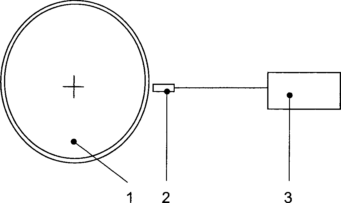
einer Brennkraftmaschine, wobei ein relativ zum Geberrad (1) feststehender
Sensor (2) die Segmente des Geberrades (1) abtastet und aus der
aufgenommenen Pulsfolge für
jedes Geberradsegment eine Winkelgeschwindigkeit berechnet wird,
wobei die Fehleridentifikation im Schubbetrieb des Motors erfolgt
und ausgehend von der kinetischen Energie der Kurbelwelle![]()
![]()
– φ .e die gemessene, fehlerbehaftete Winkelgeschwindigkeit
ist und der Fehlerwert δ'
als differentieller Winkelfehler mit φ .e = φ (1 – δ') definiert
ist
– Θ das Massenträgheitsmoment
der Kurbelwelle ist
– die
kinetische Energie in einen über
dem Kurbelwinkel konstanten, drehzahlabhängigen Anteil Ĕ und
einen gasmomentabhängigen
Anteil Ep zu Ekin = Ĕ +
Ep aufgeteilt wird
– der Anteil Ĕ mit
der über
eine Kurbelwellenumdrehung gemittelten Winkelgeschwindigkeit ![]()
![]()
– der Anteil
Ep sich...A sensor for identifying the encoder wheel error of a crankshaft sensor wheel of an internal combustion engine, wherein a relative to the encoder wheel (1) fixed sensor (2) scans the segments of the encoder wheel (1) and from the recorded pulse sequence for each Geberradsegment an angular velocity is calculated, the error identification in the overrun mode Engine takes place and based on the kinetic energy of the crankshaft ![]()
![]()
- φ. e is the measured, erroneous angular velocity and the error value δ 'as a differential angle error with φ. e = φ (1-δ ') is defined
- Θ is the mass moment of inertia of the crankshaft
- The kinetic energy is divided into a constant over the crank angle, speed-dependent component Ĕ and a gas-dependent component E p to E kin = Ĕ + E p
- The proportion Ĕ with the averaged over a crankshaft revolution angular velocity ![]()
![]()
- the proportion E p is ...
Description
Die Erfindung betrifft ein Verfahren zur Identifikation des Geberradfehlers nach dem Oberbegriff des Patentanspruches 1.The The invention relates to a method for identifying the encoder wheel error according to the preamble of claim 1.
Verfahren zur Identifikation und Kompensation des Geberradfehlers sind insbesondere zur genauen Ermittlung der Motordrehzahl und zur Lagebestimmung der Kurbelwelle notwendig. Die Motordrehzahl beeinflusst eine Reihe von Funktionen der Motorsteuerung. Fehler oder Ungenauigkeiten der Drehzahlerfassung wirken sich z. B. negativ auf die Regelkreise der Leerlauf- und Laufruheregelung aus. Weiterhin ist eine genaue Erfassung der Winkelgeschwindigkeit für kurbelwinkelgesteuerte Einspritzsysteme (z. B. Pumpe-Düse-Einspritzsysteme) notwendig, da aus der Momentan-Winkelgeschwindigkeit der Kurbelwelle Einspritzbeginn und -ende extrapoliert werden.method for identification and compensation of the Geberradfehlers are in particular for accurate determination of the engine speed and for determining the position the crankshaft necessary. The engine speed affects a number of functions of the engine control. Mistakes or inaccuracies of Speed detection affect z. B. negative on the control loops idling and running restraint off. Furthermore, an accurate detection the angular velocity for crank-angle controlled injection systems (eg pump-nozzle injection systems) necessary, because from the instantaneous angular speed of the crankshaft Injection start and end are extrapolated.
Allgemein vorbekannt ist es, zur Messung der Drehzahl und Winkellage der Kurbelwelle von Brennkraftmaschinen ein mit der Kurbelwelle umlaufendes Geberrad drehfest anzuordnen, das Markierungen oder Segmente aufweist, die von einem feststehenden Sensor abgetastet werden. Allgemein üblich sind metallische Geberräder z. B. mit einer 60-2 Zahnteilung, die von einem Hall-Sensor oder einem induktiven Geber abgetastet werden, wobei die so erzeugte Pulsfolge ausgewertet und daraus Drehzahl und Winkelstellung der Kurbelwelle berechnet werden.Generally It is previously known to measure the speed and angular position of the crankshaft of internal combustion engines with the crankshaft rotating encoder wheel to arrange rotationally fixed, having markings or segments, the be scanned by a fixed sensor. Generally common metallic donor wheels z. B. with a 60-2 tooth pitch, by a Hall sensor or an inductive encoder are sampled, wherein the thus generated Pulse sequence evaluated and from it speed and angular position of the Crankshaft be calculated.
Vorbekannt
ist aus der Schrift
Die Adaptionswerte beinhalten die vom Geberrad herrührenden Zahnteilungsfehler, Fehler der Zentrierung beim Anbau und die vom Motor durch Last- und Massenmomente sowie die von den Gaskräften herrührenden Drehungleichförmigkeiten. Die von den Massen- und Gaskräften herrührenden, auf die Kurbelwelle einwirkenden Momente wirken sich in einer ungleichmäßigen Winkelgeschwindigkeit aus, sind jedoch keine Fehler des Geberrades. Der Einfluss dieser Momente ist zudem drehzahlabhängig, sodass für verschiedene Drehzahlbereiche jeweils Korrekturwerte ermittelt werden müssen.The Adaptation values include the pitch error resulting from the encoder wheel, Error of centering during mounting and that caused by load and mass moments as well as the rotational nonuniformities resulting from the gas forces. The of the mass and gas forces originating, torques acting on the crankshaft affect at a non-uniform angular velocity but are not errors of the sender wheel. The influence of this Moments is also speed dependent, so for Different speed ranges each correction values are determined have to.
Der Erfindung liegt die Aufgabe zugrunde, den aus Fertigungstoleranzen des Geberrades sowie dessen Anbau bedingten Fehler zu identifizieren und einen segmentspezifischen, drehzahlunabhängigen Korrekturwert zum Ausgleich dieser Fehler zu ermitteln.Of the Invention is based on the object from the manufacturing tolerances identify the encoder wheel and its mounting conditional errors and a segment-specific, speed-independent correction value for compensation to determine this error.
Diese Aufgabe wird erfindungsgemäß durch die Merkmale des Patentanspruches 1 gelöst.These Task is achieved by the features of claim 1 solved.
Durch das erfindungsgemäße Verfahren wird für jedes Segment ein Korrekturwert ausgehend von der kinetischen Energie der Kurbelwelle ermittelt. Die auf die Kurbelwelle einwirkenden Momente werden erfindungsgemäß vorteilhaft in einen drehzahlabhängigen, über den Kurbelwinkel konstanten sowie einen vom Kurbelwinkel abhängigen Anteil aufgeteilt. Diese Trennung ermöglicht die Bestimmung der vom Geberrad und dessen Anbau herrührenden Fehler (Zahnteilungsfehler und Fehler der Zentrierung zur Kurbelwelle) unabhängig von den Gaskräften und Lastmomenten. Es ist damit ein drehzahlunabhängiger Fehlerwert für jedes Segment ermittelbar.By the inventive method is for each segment a correction value based on the kinetic energy the crankshaft determined. The forces acting on the crankshaft Moments are inventively advantageous in a speed-dependent, over the Crank angle constant and a dependent on the crank angle proportion divided up. This separation allows the determination of the donor wheel and its cultivation Error (tooth pitch error and error of centering to the crankshaft) independently from the gas forces and load moments. It is thus a speed independent error value for each Segment can be determined.
Erfindungsgemäß vorteilhaft können die Funktionen GSaug, GAbgas und G0 aus der Motorgeometrie und den Steuerzeiten berechnet werden. Die Korrekturwerte für die Geberradsegmente sind dabei durch die Messung der Winkelgeschwindigkeit und der Druckwerte bestimmbar.Advantageously according to the invention, the functions G suction , G exhaust gas and G 0 can be calculated from the engine geometry and the control times. The correction values for the encoder wheel segments can be determined by measuring the angular velocity and the pressure values.
Erfindungsgemäß vorteilhaft können die Parameter GSaug, GAbgas und G0 entsprechend Anspruch 2 durch Messungen in verschiedenen Drehzahlbereichen bestimmt werden. Man kann diese Parameter und somit den Fehlerwert durch Lösen eines Gleichungssystems bestimmen, wobei durch n Messungen n Gleichungen für die Bestimmung der n Unbekannten aufgestellt und gelöst werden. Im Falle der grundlegenden Verfahrensgleichung nach Anspruch 1 werden für jedes Segment 4 Messungen benötigt, um GSaug, GAb gas, G0 und δ' zu bestimmen. Advantageously according to the invention, the parameters G suction , G exhaust gas and G 0 according to claim 2 be determined by measurements in different speed ranges. One can determine these parameters and thus the error value by solving a system of equations, wherein n equations are set up and solved for the determination of the n unknowns by n measurements. In the case of the basic method according to claim 1 equation measurements are required for each segment 4 to determine G suction, G From gas, G 0 and δ '.
Wird einer oder werden mehrere der Parameter durch Berechnung bestimmt, so werden entsprechend weniger Messungen pro Segment benötigt.Becomes one or more of the parameters are determined by calculation, thus, correspondingly fewer measurements per segment are required.
Erfindungsgemäß vorteilhaft
werden entsprechend Anspruch 3 der Abgasgegendruck pAb gas und der Umgebungsdruck p0 konstant
gehalten, wodurch die Terme GAb gas·pAbgas und G0·p0 ZU E03 = GAb gas·pAbg as + G0·p0 zusammengefasst werden und sich die Verfahrensgleichung
zu![]()
![]()
In
vorteilhafter Ausgestaltung des erfindungsgemäßen Verfahrens entsprechend
Anspruch 5 werden der Saugrohrdruck pSaug,
der Abgasgegendruck pAbgas und der Umgebungsdruck
p0 konstant gehalten, wobei die G-Terme
zu E013 = GSaug·pSaug + GAbgas·PAb gas + G0·p0 zusammengefasst werden, da diese als Konstanten
im Gleichungssystem erscheinen. Der Geberradfehler δ' wird dann durch
die ![]()
![]()
In
einer weiteren vorteilhaften Ausgestaltung werden entsprechend Anspruch
6 die kurbelwinkelperiodischen Nebenmomente, wie sie z. B. vom Ventiltrieb
oder den Einspritzelementen herrühren,
in die Berechnung der kinetischen Energie der Kurbelwelle einbezogen.
Der Wechselanteil der Energie für
den Nebentrieb berechnet sich aus dem Wechselanteil M ~Neb en des Nebenmoments MNeb en durch Integration über den Kurbelwinkel φ:
Die
allgemeine Verfahrensgleichung unter Berücksichtigung der Nebenmomente
lautet dann ![]()
![]()
Die Größe ENeb en ist ein Parameter und erhöht somit nicht die Zahl der Unbekannten in der Verfahrensgleichung.The size E Neb is en a parameter and therefore does not increase the number of unknowns in the process equation.
Die Erweiterung der Verfahrensgleichung um ENeben ist bei allen Ausgestaltungen (Ansprüche 1–5) möglich, wodurch sich die Genauigkeit der Berechnung des Geberradfehlers erhöht.The extension of the method to the equation E side is possible in all of the embodiments (claims 1-5), the accuracy of calculation of Geberradfehlers thereby increased.
Weitere Einzelheiten der Erfindung werden in der Zeichnung anhand von schematisch dargestellten Ausführungsbeispielen beschrieben. Further Details of the invention are described in the drawing with reference to FIG illustrated embodiments described.
Hierbei zeigt:in this connection shows:
![]()
![]()
Das
Steuergerät
misst dadurch eine fehlerbehaftete Winkelgeschwindigkeit, die sich
damit zu ![]()
![]()
![]()
![]()
![]()
![]()
![]()
![]()
Zur
Berechnung des Geberradfehlers wird der Energieerhaltungssatz für die kinetische
Energie der Kurbelwelle nach ![]()
![]()
![]()
![]()
Die
kinetische Energie Ekin lässt sich
aufteilen in einen über
den Kurbelwinkel konstanten, aber drehzahlabhängigen Anteil Ĕ und
einen gasmomentabhängigen
Anteil Ep, woraus sich
Der
drehzahlabhängige
Anteil Ĕ ist mit der über
eine Kurbelwellenumdrehung gemittelten Winkelgeschwindigkeit ![]()
![]()
![]()
![]()
Der Anteil Ep ist aufgrund der periodischen Ladungswechsel-, Kompressions- und Verbrennungskräfte abhängig vom Saugrohrdruck und dem Verbrennungsverlauf.The proportion E p is due to the periodic gas exchange, compression and combustion forces depending on the intake manifold pressure and the combustion process.
Im
Schub findet keine Verbrennung statt, somit gibt es auch keine Verbrennungskräfte. Die
Energiebeiträge
von Ladungswechsel, Kompression und Expansion lassen sich in einen
zum Saugrohrdruck pSaug proportionalen Anteil,
einen zum Abgasgegendruck pAbgas proportionalen
Anteil und einen zum Umgebungsdruck p0 abhängigen Anteil
aufteilen. Daraus ergibt sich
Die Funktionen GSaug, GAbgas und G0 sind Funktionen des Kurbelwinkels, abhängig von den konstruktiven Abmessungen des Kurbeltriebs und den Ventilsteuerzeiten.The functions G suction , G exhaust and G 0 are functions of the crank angle, depending on the constructive dimensions of the crank mechanism and the valve timing.
Die
gesamte kinetische Energie Ekin wird durch
folgende Formel beschrieben
Eingesetzt
in (7) ergibt sich die allgemeine Grundgleichung des Verfahrens
zu ![]()
![]()
Aus dieser allgemeinen Verfahrensgleichung lassen sich mehrere Teilverfahren ableiten, welche sich hinsichtlich der Randbedingungen und des Rechenaufwands unterscheiden.Out This general process equation allows several sub-processes derive, which in terms of the boundary conditions and the computational effort differ.
Für das allgemeine Verfahren erfolgen keine Annahmen bzw. Voraussetzungen bezüglich GSaug, GAbgas und G0, wodurch die allgemeine Verfahrensgleichung folgende vier Unbekannte GSaug, GAb gas, G0 und δ' beinhaltet. Zur Lösung dieser Gleichung müssen für jeden Kurbelwinkel die Momentangeschwindigkeit φ .e als auch die Parameter pSaug, pAbgas und p0 für jeden Zahn bei mindestens vier Umdrehungen gemessen werden. Die Daten der vier Messungen bilden ein Gleichungssystem mit vier Gleichungen.Done for the general method no assumptions or requirements regarding G suction, exhaust G and G 0, which the general method equation, the following four unknowns G suction, G From gas, G includes 0 and δ '. To solve this equation, the instantaneous velocity φ must be determined for each crank angle. e as well as the parameters p suction , p exhaust and p 0 are measured for each tooth at least four revolutions. The data of the four measurements form a system of equations with four equations.
Für die gemessenen vier Umdrehungen müssen die mittleren Geschwindigkeiten voneinander verschieden sein, um unabhängige Gleichungen zu erhalten. Durch Lösen des Gleichungssystems kann für jede Winkelstellung ein zugehöriger differentieller Geberradfehler δ' ermittelt werden.For the measured four turns the mean velocities differ from each other independent To get equations. By loosening of the equation system can for each angular position is an associated one differential encoder wheel error δ 'are determined.
Die Funktionen GSaug, GAbgas und G0 ergeben sich aus der Motorgeometrie und den Ventilsteuerzeiten, sie sind somit als Parameter der allgemeinen Verfahrensgleichung berechenbar. Für jede explizite Berechnung einer G-Funktion reduziert sich die Zahl der Bestimmungsgleichungen und damit die Zahl der notwendigen Messungen um eins. Werden alle Parameter berechnet und die Druckwerte gemessen, ist ein Messwert pro Winkelstellung ausreichend.The functions G suction , G exhaust and G 0 result from the engine geometry and the valve timing, they are thus calculable as parameters of the general process equation. For every explicit calculation of a G-function, the number of determinate equations and thus the number of necessary measurements is reduced by one. If all parameters are calculated and the pressure values are measured, one measured value per angular position is sufficient.
Werden
während
der Messungen der Abgasgegendruck pAbgas und
der Umgebungsdruck p0 konstant gehalten,
so können
die Terme GAb gas·pAb gas und G0·p0 zu ![]()
![]()
Für die drei Unbekannten GSaug, E03 und δ' müssen analog zu dem allgemeinen Verfahren drei Messungen durchgeführt werden. Die Funktion GSaug kann hierbei wiederum berechnet werden, sodass nur noch die Unbekannten E03 und δ' bleiben und zwei Bestimmungsmessungen ausreichen.For the three unknowns G suction , E 03 and δ ', three measurements must be carried out analogously to the general method. The function G suction can be calculated again, so that only the unknowns E 03 and δ 'remain and two determinations are sufficient.
Werden
für die
Messungen der Saugrohrdruck pSaug, der Abgasgegendruck
pAbgas und der Umgebungsdruck p0 konstant
gehalten, so können
die G-Terme zu
![]()
![]()
Bei erkanntem Schubbetrieb wird als weitere Bedingung geprüft, ob Ladedruck und AGR-Steller im Messbetrieb arbeiten, d. h. ob die zur Lösung der Gleichung benötigten Druckmesswerte ermittelt bzw. auf deren konstanten Wert hin überprüft werden können. Nachfolgend wird das Verbleiben im Schubbetrieb überprüft und bei Unterschreiten einer ersten Messdrehzahl die Messung der segmentspezifischen Durchlaufzeiten bzw. der daraus ermittelten Winkelgeschwindigkeiten gestartet und für eine weitere Berechnung gespeichert. Befindet sich das Fahrzeug weiterhin im Schubbetrieb und wird eine zweite Messdrehzahl unterschritten, wird der zweite Drehzahlverlauf aufgezeichnet. Durch die Messpunkte in unterschiedlichen Drehzahlbereichen können zwei unabhängige Gleichungen zur Lösung des Gleichungssystems aufgestellt werden. Für jedes Geberradsegment steht nach Lösen des Gleichungssystems der differentielle Geberradfehler δ' nach Gleichung (3) zur Verfügung, woraus nach Gleichung (5) die korrekte Winkelgeschwindigkeit φ . ermittelt werden kann.at detected overrun is checked as a further condition, whether boost pressure and EGR controllers operate in measuring mode, d. H. whether the pressure readings needed to solve the equation can be determined or checked for their constant value. Below is the Stay checked in overrun mode and at Below a first measuring speed, the measurement of the segment-specific Throughput times or the angular velocities determined therefrom started and for saved another calculation. Is the vehicle located continue in overrun and a second measuring speed is exceeded, the second speed profile is recorded. Through the measuring points in different speed ranges can have two independent equations to the solution of the equation system are set up. Stands for each sender wheel segment after loosening of the system of equations the differential encoder wheel error δ 'according to equation (3) to disposal, from which equation (5) the correct angular velocity φ. determined can be.
Bezugszeichenliste 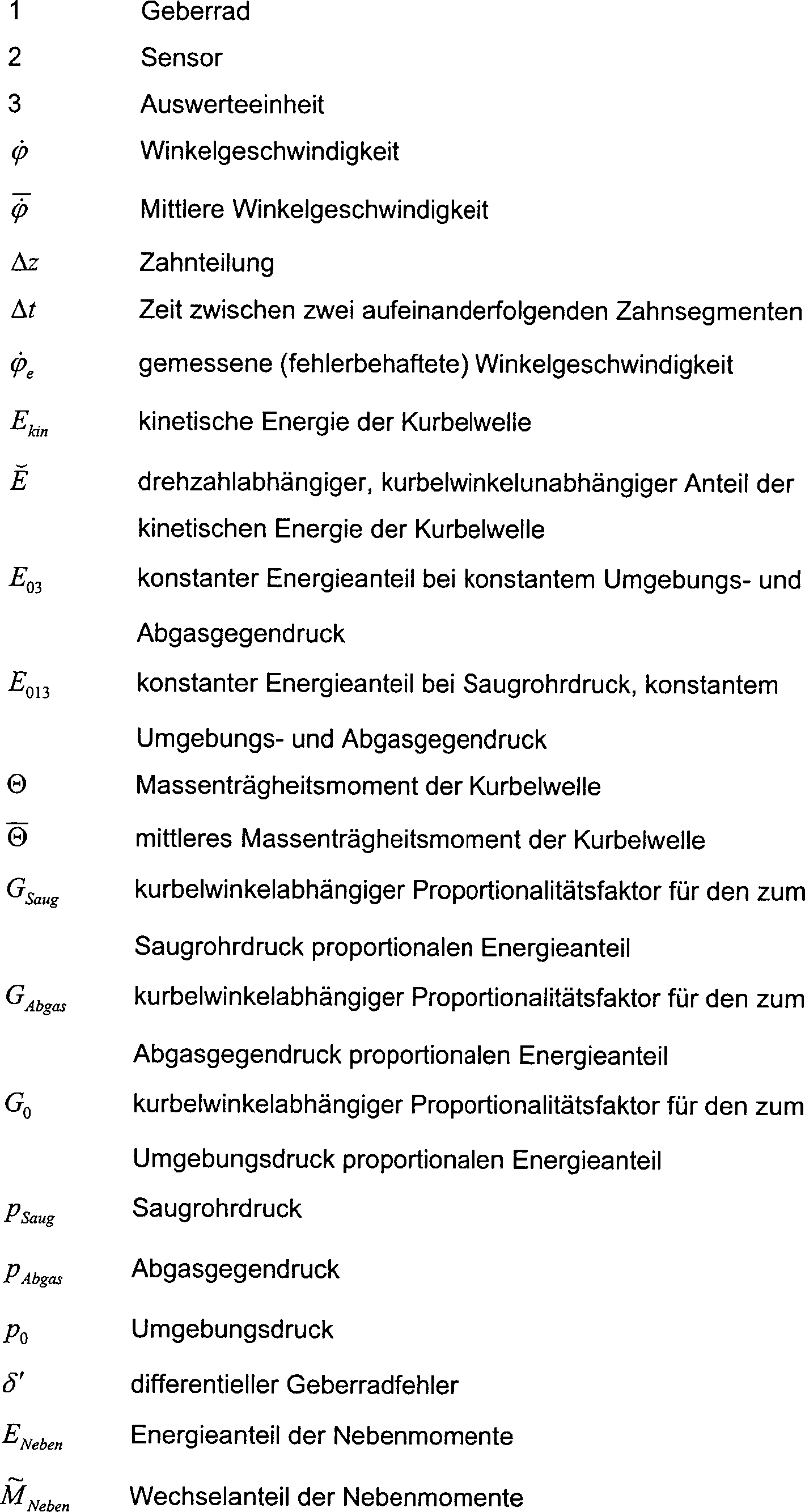
Claims (6)
Priority Applications (1)
| Application Number | Priority Date | Filing Date | Title |
|---|---|---|---|
| DE2001107892 DE10107892B4 (en) | 2001-02-16 | 2001-02-16 | Method for identifying the encoder wheel error while driving |
Applications Claiming Priority (1)
| Application Number | Priority Date | Filing Date | Title |
|---|---|---|---|
| DE2001107892 DE10107892B4 (en) | 2001-02-16 | 2001-02-16 | Method for identifying the encoder wheel error while driving |
Publications (2)
| Publication Number | Publication Date |
|---|---|
| DE10107892A1 DE10107892A1 (en) | 2002-09-05 |
| DE10107892B4 true DE10107892B4 (en) | 2005-07-07 |
Family
ID=7674697
Family Applications (1)
| Application Number | Title | Priority Date | Filing Date |
|---|---|---|---|
| DE2001107892 Expired - Fee Related DE10107892B4 (en) | 2001-02-16 | 2001-02-16 | Method for identifying the encoder wheel error while driving |
Country Status (1)
| Country | Link |
|---|---|
| DE (1) | DE10107892B4 (en) |
Cited By (2)
| Publication number | Priority date | Publication date | Assignee | Title |
|---|---|---|---|---|
| DE102010054532A1 (en) | 2010-12-15 | 2012-06-21 | Volkswagen Ag | Method for automatically determining a sensor wheel error of an internal combustion engine |
| DE102007046509B4 (en) * | 2006-10-03 | 2014-12-24 | GM Global Technology Operations LLC (n. d. Ges. d. Staates Delaware) | Engine system and method for disturbance compensation of a crank signal |
Families Citing this family (4)
| Publication number | Priority date | Publication date | Assignee | Title |
|---|---|---|---|---|
| DE10256106B4 (en) * | 2002-11-29 | 2006-01-12 | Audi Ag | Apparatus and method for estimating engine torque |
| DE102005009914A1 (en) | 2004-03-01 | 2005-10-20 | Bosch Gmbh Robert | Acquisition of an angular position signal for an internal combustion engine, with the signal being corrected using a value derived from angular velocity and combustion chamber pressure measurements |
| DE102010051369B4 (en) | 2010-11-13 | 2023-12-28 | Volkswagen Aktiengesellschaft | Method and device for determining an indicated torque and an indicated mean pressure of a cylinder of an internal combustion engine |
| DE102019219278A1 (en) * | 2019-12-11 | 2021-06-17 | Volkswagen Aktiengesellschaft | Method for determining the camshaft position of a series engine |
Citations (1)
| Publication number | Priority date | Publication date | Assignee | Title |
|---|---|---|---|---|
| DE19540674A1 (en) * | 1995-10-31 | 1997-05-07 | Siemens Ag | Correcting tolerances of sensor wheel used in angular velocity measurement of shaft in internal combustion engine |
-
2001
- 2001-02-16 DE DE2001107892 patent/DE10107892B4/en not_active Expired - Fee Related
Patent Citations (1)
| Publication number | Priority date | Publication date | Assignee | Title |
|---|---|---|---|---|
| DE19540674A1 (en) * | 1995-10-31 | 1997-05-07 | Siemens Ag | Correcting tolerances of sensor wheel used in angular velocity measurement of shaft in internal combustion engine |
Cited By (3)
| Publication number | Priority date | Publication date | Assignee | Title |
|---|---|---|---|---|
| DE102007046509B4 (en) * | 2006-10-03 | 2014-12-24 | GM Global Technology Operations LLC (n. d. Ges. d. Staates Delaware) | Engine system and method for disturbance compensation of a crank signal |
| DE102010054532A1 (en) | 2010-12-15 | 2012-06-21 | Volkswagen Ag | Method for automatically determining a sensor wheel error of an internal combustion engine |
| EP2492475A1 (en) | 2010-12-15 | 2012-08-29 | Volkswagen Aktiengesellschaft | Method for automatic detection of a rotary encoder error of a combustion engine |
Also Published As
| Publication number | Publication date |
|---|---|
| DE10107892A1 (en) | 2002-09-05 |
Similar Documents
| Publication | Publication Date | Title |
|---|---|---|
| DE4227104C2 (en) | Method and system for detecting misfire of a piston internal combustion engine | |
| EP0489059B1 (en) | Process and apparatus for monitoring the power output of the individual cylinders of a multicylinder internal combustion engine | |
| DE19540674C2 (en) | Adaptation procedure for correcting tolerances of an encoder wheel | |
| EP1525382B1 (en) | Regulating the mode of operation of an internal combustion engine | |
| DE69006287T2 (en) | System for detecting the pressure in the cylinder of an internal combustion engine. | |
| EP2807362B1 (en) | Method for determining a dead time of an exhaust gas sensor of an internal combustion engine | |
| EP0474711B1 (en) | Process for determining the combustion air mass in the cylinders of an internal combustion engine | |
| DE602004004493T2 (en) | Device for calibrating a pressure measuring chain in a cylinder of a motor vehicle diesel engine | |
| DE102008039572B4 (en) | Method for collecting position data of an internal combustion engine crankshaft of a hybrid drive system | |
| WO2006131435A1 (en) | Method and device for correcting the signal of a sensor | |
| DE19544720C1 (en) | Internal combustion engine misfiring detection method e.g. for multiple cylinder engines | |
| DE19540675C1 (en) | Torque estimation method using evaluation of internal combustion engine revolution rate for engine control | |
| DE4445684C2 (en) | Procedure for determining torques, work and performance on internal combustion engines | |
| DE4215581B4 (en) | System for controlling a solenoid-controlled fuel metering device | |
| DE102007024416A1 (en) | Method for detecting current and future turning parameter of crankshaft of combustion engine, involves determining rotating parameter of camshaft from control unit that obtains signal from camshaft sensor | |
| EP1723331B1 (en) | Method and device for detecting the angular position signal in an internal combustion engine | |
| AT396406B (en) | DEVICE FOR ELECTRONICALLY MEASURING THE SPEED OF INTERNAL COMBUSTION ENGINES | |
| WO2001023735A1 (en) | Method for detecting combustion misses | |
| DE10107892B4 (en) | Method for identifying the encoder wheel error while driving | |
| WO2014086980A2 (en) | Method for determining a cylinder pressure-crankshaft position assignment for an internal combustion engine | |
| DE4231322C2 (en) | Misfire detection device for an internal combustion engine | |
| DE112019000524T5 (en) | AIR FLOW RATE MEASURING DEVICE | |
| DE19627540B4 (en) | Misfire detection method | |
| DE102008044305B4 (en) | Method, control device and computer program product for detecting the uneven running of a multi-cylinder internal combustion engine | |
| DE19633680B4 (en) | Device for correcting a measurement error |
Legal Events
| Date | Code | Title | Description |
|---|---|---|---|
| 8110 | Request for examination paragraph 44 | ||
| 8364 | No opposition during term of opposition | ||
| R119 | Application deemed withdrawn, or ip right lapsed, due to non-payment of renewal fee |
Effective date: 20130903 |