DE10084227B3 - Creep-resistant elastic composite material and method for its production - Google Patents
Creep-resistant elastic composite material and method for its production Download PDFInfo
- Publication number
- DE10084227B3 DE10084227B3 DE10084227T DE10084227T DE10084227B3 DE 10084227 B3 DE10084227 B3 DE 10084227B3 DE 10084227 T DE10084227 T DE 10084227T DE 10084227 T DE10084227 T DE 10084227T DE 10084227 B3 DE10084227 B3 DE 10084227B3
- Authority
- DE
- Germany
- Prior art keywords
- elastomeric
- elastic
- roll
- layer
- fibrous web
- Prior art date
- Legal status (The legal status is an assumption and is not a legal conclusion. Google has not performed a legal analysis and makes no representation as to the accuracy of the status listed.)
- Expired - Fee Related
Links
- 239000002131 composite material Substances 0.000 title claims abstract description 80
- 238000004519 manufacturing process Methods 0.000 title claims abstract description 14
- 238000000034 method Methods 0.000 title claims description 50
- 239000013013 elastic material Substances 0.000 claims abstract description 58
- 239000000463 material Substances 0.000 claims description 123
- 239000000835 fiber Substances 0.000 claims description 105
- 229920000642 polymer Polymers 0.000 claims description 48
- 229920001400 block copolymer Polymers 0.000 claims description 32
- 230000008569 process Effects 0.000 claims description 20
- 229910052751 metal Inorganic materials 0.000 claims description 7
- 239000002184 metal Substances 0.000 claims description 7
- 239000002952 polymeric resin Substances 0.000 claims description 7
- 229920003002 synthetic resin Polymers 0.000 claims description 7
- 229920001200 poly(ethylene-vinyl acetate) Polymers 0.000 claims description 6
- 229920000570 polyether Polymers 0.000 claims description 4
- 229920002635 polyurethane Polymers 0.000 claims description 4
- 239000004814 polyurethane Substances 0.000 claims description 4
- 239000004721 Polyphenylene oxide Substances 0.000 claims description 3
- 230000015572 biosynthetic process Effects 0.000 claims description 2
- 238000011068 loading method Methods 0.000 claims description 2
- 239000013536 elastomeric material Substances 0.000 claims 1
- HDERJYVLTPVNRI-UHFFFAOYSA-N ethene;ethenyl acetate Chemical class C=C.CC(=O)OC=C HDERJYVLTPVNRI-UHFFFAOYSA-N 0.000 claims 1
- 238000012360 testing method Methods 0.000 description 32
- -1 ethylene-butylene Chemical group 0.000 description 31
- 238000003490 calendering Methods 0.000 description 28
- 239000000203 mixture Substances 0.000 description 21
- 230000000052 comparative effect Effects 0.000 description 20
- 229920001410 Microfiber Polymers 0.000 description 14
- 239000007789 gas Substances 0.000 description 14
- 239000003658 microfiber Substances 0.000 description 14
- 239000011347 resin Substances 0.000 description 11
- 229920005989 resin Polymers 0.000 description 11
- 229920001169 thermoplastic Polymers 0.000 description 11
- 239000004743 Polypropylene Substances 0.000 description 9
- 229920001155 polypropylene Polymers 0.000 description 9
- 239000000126 substance Substances 0.000 description 9
- 229920001577 copolymer Polymers 0.000 description 8
- 238000001125 extrusion Methods 0.000 description 8
- 239000004698 Polyethylene Substances 0.000 description 7
- 230000036760 body temperature Effects 0.000 description 7
- 210000004177 elastic tissue Anatomy 0.000 description 7
- 238000010438 heat treatment Methods 0.000 description 7
- 238000001878 scanning electron micrograph Methods 0.000 description 7
- 239000004793 Polystyrene Substances 0.000 description 6
- 230000002745 absorbent Effects 0.000 description 6
- 239000002250 absorbent Substances 0.000 description 6
- 230000000694 effects Effects 0.000 description 6
- 229920001971 elastomer Polymers 0.000 description 6
- 239000004744 fabric Substances 0.000 description 6
- 229920000098 polyolefin Polymers 0.000 description 6
- 229920002223 polystyrene Polymers 0.000 description 6
- 229920002633 Kraton (polymer) Polymers 0.000 description 5
- PPBRXRYQALVLMV-UHFFFAOYSA-N Styrene Natural products C=CC1=CC=CC=C1 PPBRXRYQALVLMV-UHFFFAOYSA-N 0.000 description 5
- 230000006399 behavior Effects 0.000 description 5
- 238000002844 melting Methods 0.000 description 5
- 230000008018 melting Effects 0.000 description 5
- 239000002245 particle Substances 0.000 description 5
- 229920000573 polyethylene Polymers 0.000 description 5
- 239000000047 product Substances 0.000 description 5
- 238000012549 training Methods 0.000 description 5
- 238000011282 treatment Methods 0.000 description 5
- VGGSQFUCUMXWEO-UHFFFAOYSA-N Ethene Chemical compound C=C VGGSQFUCUMXWEO-UHFFFAOYSA-N 0.000 description 4
- 239000005977 Ethylene Substances 0.000 description 4
- 239000006057 Non-nutritive feed additive Substances 0.000 description 4
- 229920002614 Polyether block amide Polymers 0.000 description 4
- 229920001131 Pulp (paper) Polymers 0.000 description 4
- 230000001427 coherent effect Effects 0.000 description 4
- 239000000806 elastomer Substances 0.000 description 4
- 239000006228 supernatant Substances 0.000 description 4
- 239000004416 thermosoftening plastic Substances 0.000 description 4
- 210000001519 tissue Anatomy 0.000 description 4
- 239000013032 Hydrocarbon resin Substances 0.000 description 3
- KFZMGEQAYNKOFK-UHFFFAOYSA-N Isopropanol Chemical compound CC(C)O KFZMGEQAYNKOFK-UHFFFAOYSA-N 0.000 description 3
- 238000001994 activation Methods 0.000 description 3
- 230000002411 adverse Effects 0.000 description 3
- 150000001412 amines Chemical class 0.000 description 3
- 229920001198 elastomeric copolymer Polymers 0.000 description 3
- 210000000416 exudates and transudate Anatomy 0.000 description 3
- 229920006270 hydrocarbon resin Polymers 0.000 description 3
- 230000006872 improvement Effects 0.000 description 3
- 239000002648 laminated material Substances 0.000 description 3
- 238000003475 lamination Methods 0.000 description 3
- 239000011159 matrix material Substances 0.000 description 3
- 239000000178 monomer Substances 0.000 description 3
- 239000008188 pellet Substances 0.000 description 3
- 230000000704 physical effect Effects 0.000 description 3
- 239000000049 pigment Substances 0.000 description 3
- 238000002360 preparation method Methods 0.000 description 3
- 238000012545 processing Methods 0.000 description 3
- 239000012815 thermoplastic material Substances 0.000 description 3
- 230000000699 topical effect Effects 0.000 description 3
- VXNZUUAINFGPBY-UHFFFAOYSA-N 1-Butene Chemical compound CCC=C VXNZUUAINFGPBY-UHFFFAOYSA-N 0.000 description 2
- LIKMAJRDDDTEIG-UHFFFAOYSA-N 1-hexene Chemical compound CCCCC=C LIKMAJRDDDTEIG-UHFFFAOYSA-N 0.000 description 2
- KWKAKUADMBZCLK-UHFFFAOYSA-N 1-octene Chemical compound CCCCCCC=C KWKAKUADMBZCLK-UHFFFAOYSA-N 0.000 description 2
- XKRFYHLGVUSROY-UHFFFAOYSA-N Argon Chemical compound [Ar] XKRFYHLGVUSROY-UHFFFAOYSA-N 0.000 description 2
- OKTJSMMVPCPJKN-UHFFFAOYSA-N Carbon Chemical compound [C] OKTJSMMVPCPJKN-UHFFFAOYSA-N 0.000 description 2
- 206010021639 Incontinence Diseases 0.000 description 2
- RRHGJUQNOFWUDK-UHFFFAOYSA-N Isoprene Chemical group CC(=C)C=C RRHGJUQNOFWUDK-UHFFFAOYSA-N 0.000 description 2
- 239000004952 Polyamide Substances 0.000 description 2
- 230000004913 activation Effects 0.000 description 2
- 238000005452 bending Methods 0.000 description 2
- 230000008901 benefit Effects 0.000 description 2
- 239000003795 chemical substances by application Substances 0.000 description 2
- 230000008602 contraction Effects 0.000 description 2
- 125000004122 cyclic group Chemical group 0.000 description 2
- 230000003247 decreasing effect Effects 0.000 description 2
- 230000001419 dependent effect Effects 0.000 description 2
- PRAKJMSDJKAYCZ-UHFFFAOYSA-N dodecahydrosqualene Natural products CC(C)CCCC(C)CCCC(C)CCCCC(C)CCCC(C)CCCC(C)C PRAKJMSDJKAYCZ-UHFFFAOYSA-N 0.000 description 2
- 230000029142 excretion Effects 0.000 description 2
- 230000006870 function Effects 0.000 description 2
- 239000000416 hydrocolloid Substances 0.000 description 2
- 239000000017 hydrogel Substances 0.000 description 2
- 239000000155 melt Substances 0.000 description 2
- 238000012986 modification Methods 0.000 description 2
- 230000004048 modification Effects 0.000 description 2
- 239000004745 nonwoven fabric Substances 0.000 description 2
- 239000003921 oil Substances 0.000 description 2
- 238000000399 optical microscopy Methods 0.000 description 2
- 230000002093 peripheral effect Effects 0.000 description 2
- 229920002647 polyamide Polymers 0.000 description 2
- 229920000728 polyester Polymers 0.000 description 2
- 238000011084 recovery Methods 0.000 description 2
- 230000002829 reductive effect Effects 0.000 description 2
- 238000011160 research Methods 0.000 description 2
- 230000002441 reversible effect Effects 0.000 description 2
- 239000005060 rubber Substances 0.000 description 2
- 239000002904 solvent Substances 0.000 description 2
- 229920003046 tetrablock copolymer Polymers 0.000 description 2
- 230000036962 time dependent Effects 0.000 description 2
- 229920002554 vinyl polymer Polymers 0.000 description 2
- DMYOHQBLOZMDLP-UHFFFAOYSA-N 1-[2-(2-hydroxy-3-piperidin-1-ylpropoxy)phenyl]-3-phenylpropan-1-one Chemical compound C1CCCCN1CC(O)COC1=CC=CC=C1C(=O)CCC1=CC=CC=C1 DMYOHQBLOZMDLP-UHFFFAOYSA-N 0.000 description 1
- IVVLFHBYPHTMJU-UHFFFAOYSA-N 2,2,4,4-tetramethyl-7-oxa-3,20-diazadispiro[5.1.11^{8}.2^{6}]henicosan-21-one Chemical compound C1C(C)(C)NC(C)(C)CC21C(=O)NC1(CCCCCCCCCCC1)O2 IVVLFHBYPHTMJU-UHFFFAOYSA-N 0.000 description 1
- JLZIIHMTTRXXIN-UHFFFAOYSA-N 2-(2-hydroxy-4-methoxybenzoyl)benzoic acid Chemical compound OC1=CC(OC)=CC=C1C(=O)C1=CC=CC=C1C(O)=O JLZIIHMTTRXXIN-UHFFFAOYSA-N 0.000 description 1
- MJBPUQUGJNAPAZ-AWEZNQCLSA-N Butin Natural products C1([C@@H]2CC(=O)C3=CC=C(C=C3O2)O)=CC=C(O)C(O)=C1 MJBPUQUGJNAPAZ-AWEZNQCLSA-N 0.000 description 1
- MJBPUQUGJNAPAZ-UHFFFAOYSA-N Butine Natural products O1C2=CC(O)=CC=C2C(=O)CC1C1=CC=C(O)C(O)=C1 MJBPUQUGJNAPAZ-UHFFFAOYSA-N 0.000 description 1
- 101100232929 Caenorhabditis elegans pat-4 gene Proteins 0.000 description 1
- 229920000298 Cellophane Polymers 0.000 description 1
- 229920001634 Copolyester Polymers 0.000 description 1
- 235000013175 Crataegus laevigata Nutrition 0.000 description 1
- XZMCDFZZKTWFGF-UHFFFAOYSA-N Cyanamide Chemical compound NC#N XZMCDFZZKTWFGF-UHFFFAOYSA-N 0.000 description 1
- 239000004606 Fillers/Extenders Substances 0.000 description 1
- 241001539176 Hime Species 0.000 description 1
- 229920002292 Nylon 6 Polymers 0.000 description 1
- 239000004372 Polyvinyl alcohol Substances 0.000 description 1
- 239000004959 Rilsan Substances 0.000 description 1
- 229920002472 Starch Polymers 0.000 description 1
- 229920001079 Thiokol (polymer) Polymers 0.000 description 1
- 239000013036 UV Light Stabilizer Substances 0.000 description 1
- XTXRWKRVRITETP-UHFFFAOYSA-N Vinyl acetate Chemical class CC(=O)OC=C XTXRWKRVRITETP-UHFFFAOYSA-N 0.000 description 1
- 230000001133 acceleration Effects 0.000 description 1
- 230000009471 action Effects 0.000 description 1
- 239000000654 additive Substances 0.000 description 1
- 239000000853 adhesive Substances 0.000 description 1
- 230000001070 adhesive effect Effects 0.000 description 1
- 150000001335 aliphatic alkanes Chemical class 0.000 description 1
- 150000001336 alkenes Chemical class 0.000 description 1
- 229920005603 alternating copolymer Polymers 0.000 description 1
- 239000002216 antistatic agent Substances 0.000 description 1
- 238000013459 approach Methods 0.000 description 1
- 229910052786 argon Inorganic materials 0.000 description 1
- 230000000712 assembly Effects 0.000 description 1
- 238000000429 assembly Methods 0.000 description 1
- 230000004888 barrier function Effects 0.000 description 1
- 239000011230 binding agent Substances 0.000 description 1
- IAQRGUVFOMOMEM-UHFFFAOYSA-N butene Natural products CC=CC IAQRGUVFOMOMEM-UHFFFAOYSA-N 0.000 description 1
- 238000005266 casting Methods 0.000 description 1
- 238000012512 characterization method Methods 0.000 description 1
- 238000006243 chemical reaction Methods 0.000 description 1
- 239000011248 coating agent Substances 0.000 description 1
- 238000000576 coating method Methods 0.000 description 1
- 239000003086 colorant Substances 0.000 description 1
- 150000001875 compounds Chemical class 0.000 description 1
- 238000000748 compression moulding Methods 0.000 description 1
- 238000010924 continuous production Methods 0.000 description 1
- 238000005520 cutting process Methods 0.000 description 1
- 230000001066 destructive effect Effects 0.000 description 1
- 150000001993 dienes Chemical class 0.000 description 1
- 238000007598 dipping method Methods 0.000 description 1
- 238000006073 displacement reaction Methods 0.000 description 1
- 230000009977 dual effect Effects 0.000 description 1
- 150000002148 esters Chemical class 0.000 description 1
- 229920001038 ethylene copolymer Polymers 0.000 description 1
- 230000009970 fire resistant effect Effects 0.000 description 1
- 239000012530 fluid Substances 0.000 description 1
- NBVXSUQYWXRMNV-UHFFFAOYSA-N fluoromethane Chemical compound FC NBVXSUQYWXRMNV-UHFFFAOYSA-N 0.000 description 1
- 238000009472 formulation Methods 0.000 description 1
- 125000000524 functional group Chemical group 0.000 description 1
- PCHJSUWPFVWCPO-UHFFFAOYSA-N gold Chemical compound [Au] PCHJSUWPFVWCPO-UHFFFAOYSA-N 0.000 description 1
- 239000010931 gold Substances 0.000 description 1
- 229910052737 gold Inorganic materials 0.000 description 1
- 229920000578 graft copolymer Polymers 0.000 description 1
- 229920001903 high density polyethylene Polymers 0.000 description 1
- 239000004700 high-density polyethylene Substances 0.000 description 1
- 229920001519 homopolymer Polymers 0.000 description 1
- 238000003384 imaging method Methods 0.000 description 1
- 230000003993 interaction Effects 0.000 description 1
- 230000002427 irreversible effect Effects 0.000 description 1
- 230000007794 irritation Effects 0.000 description 1
- 238000010030 laminating Methods 0.000 description 1
- 229920000092 linear low density polyethylene Polymers 0.000 description 1
- 239000004707 linear low-density polyethylene Substances 0.000 description 1
- 239000007788 liquid Substances 0.000 description 1
- 229920001684 low density polyethylene Polymers 0.000 description 1
- 239000004702 low-density polyethylene Substances 0.000 description 1
- 238000002156 mixing Methods 0.000 description 1
- 150000002763 monocarboxylic acids Chemical class 0.000 description 1
- 238000000465 moulding Methods 0.000 description 1
- TVMXDCGIABBOFY-UHFFFAOYSA-N n-Octanol Natural products CCCCCCCC TVMXDCGIABBOFY-UHFFFAOYSA-N 0.000 description 1
- 230000036961 partial effect Effects 0.000 description 1
- 229920003023 plastic Polymers 0.000 description 1
- 239000004033 plastic Substances 0.000 description 1
- 229920001083 polybutene Polymers 0.000 description 1
- 229920001707 polybutylene terephthalate Polymers 0.000 description 1
- 229920000139 polyethylene terephthalate Polymers 0.000 description 1
- 239000005020 polyethylene terephthalate Substances 0.000 description 1
- 239000004810 polytetrafluoroethylene Substances 0.000 description 1
- 229920001343 polytetrafluoroethylene Polymers 0.000 description 1
- 229920002689 polyvinyl acetate Polymers 0.000 description 1
- 239000011118 polyvinyl acetate Substances 0.000 description 1
- 229920002451 polyvinyl alcohol Polymers 0.000 description 1
- QQONPFPTGQHPMA-UHFFFAOYSA-N propylene Natural products CC=C QQONPFPTGQHPMA-UHFFFAOYSA-N 0.000 description 1
- 229920005604 random copolymer Polymers 0.000 description 1
- 230000009467 reduction Effects 0.000 description 1
- 239000005871 repellent Substances 0.000 description 1
- 229910001927 ruthenium tetroxide Inorganic materials 0.000 description 1
- 238000007665 sagging Methods 0.000 description 1
- 229920006395 saturated elastomer Polymers 0.000 description 1
- 238000004626 scanning electron microscopy Methods 0.000 description 1
- 230000007958 sleep Effects 0.000 description 1
- 239000007787 solid Substances 0.000 description 1
- 238000005507 spraying Methods 0.000 description 1
- 239000003381 stabilizer Substances 0.000 description 1
- 235000019698 starch Nutrition 0.000 description 1
- 239000000758 substrate Substances 0.000 description 1
- 230000003655 tactile properties Effects 0.000 description 1
- 238000009864 tensile test Methods 0.000 description 1
- 229920001897 terpolymer Polymers 0.000 description 1
- 238000010998 test method Methods 0.000 description 1
- 238000004154 testing of material Methods 0.000 description 1
- 229920006344 thermoplastic copolyester Polymers 0.000 description 1
- 229920005992 thermoplastic resin Polymers 0.000 description 1
- 125000000391 vinyl group Chemical group [H]C([*])=C([H])[H] 0.000 description 1
- 238000005303 weighing Methods 0.000 description 1
Images


Classifications
-
- B—PERFORMING OPERATIONS; TRANSPORTING
- B32—LAYERED PRODUCTS
- B32B—LAYERED PRODUCTS, i.e. PRODUCTS BUILT-UP OF STRATA OF FLAT OR NON-FLAT, e.g. CELLULAR OR HONEYCOMB, FORM
- B32B27/00—Layered products comprising a layer of synthetic resin
- B32B27/12—Layered products comprising a layer of synthetic resin next to a fibrous or filamentary layer
-
- D—TEXTILES; PAPER
- D04—BRAIDING; LACE-MAKING; KNITTING; TRIMMINGS; NON-WOVEN FABRICS
- D04H—MAKING TEXTILE FABRICS, e.g. FROM FIBRES OR FILAMENTARY MATERIAL; FABRICS MADE BY SUCH PROCESSES OR APPARATUS, e.g. FELTS, NON-WOVEN FABRICS; COTTON-WOOL; WADDING ; NON-WOVEN FABRICS FROM STAPLE FIBRES, FILAMENTS OR YARNS, BONDED WITH AT LEAST ONE WEB-LIKE MATERIAL DURING THEIR CONSOLIDATION
- D04H13/00—Other non-woven fabrics
-
- B—PERFORMING OPERATIONS; TRANSPORTING
- B32—LAYERED PRODUCTS
- B32B—LAYERED PRODUCTS, i.e. PRODUCTS BUILT-UP OF STRATA OF FLAT OR NON-FLAT, e.g. CELLULAR OR HONEYCOMB, FORM
- B32B1/00—Layered products having a non-planar shape
- B32B1/08—Tubular products
-
- B—PERFORMING OPERATIONS; TRANSPORTING
- B32—LAYERED PRODUCTS
- B32B—LAYERED PRODUCTS, i.e. PRODUCTS BUILT-UP OF STRATA OF FLAT OR NON-FLAT, e.g. CELLULAR OR HONEYCOMB, FORM
- B32B5/00—Layered products characterised by the non- homogeneity or physical structure, i.e. comprising a fibrous, filamentary, particulate or foam layer; Layered products characterised by having a layer differing constitutionally or physically in different parts
- B32B5/02—Layered products characterised by the non- homogeneity or physical structure, i.e. comprising a fibrous, filamentary, particulate or foam layer; Layered products characterised by having a layer differing constitutionally or physically in different parts characterised by structural features of a fibrous or filamentary layer
- B32B5/022—Non-woven fabric
-
- B—PERFORMING OPERATIONS; TRANSPORTING
- B32—LAYERED PRODUCTS
- B32B—LAYERED PRODUCTS, i.e. PRODUCTS BUILT-UP OF STRATA OF FLAT OR NON-FLAT, e.g. CELLULAR OR HONEYCOMB, FORM
- B32B5/00—Layered products characterised by the non- homogeneity or physical structure, i.e. comprising a fibrous, filamentary, particulate or foam layer; Layered products characterised by having a layer differing constitutionally or physically in different parts
- B32B5/02—Layered products characterised by the non- homogeneity or physical structure, i.e. comprising a fibrous, filamentary, particulate or foam layer; Layered products characterised by having a layer differing constitutionally or physically in different parts characterised by structural features of a fibrous or filamentary layer
- B32B5/026—Knitted fabric
-
- B—PERFORMING OPERATIONS; TRANSPORTING
- B32—LAYERED PRODUCTS
- B32B—LAYERED PRODUCTS, i.e. PRODUCTS BUILT-UP OF STRATA OF FLAT OR NON-FLAT, e.g. CELLULAR OR HONEYCOMB, FORM
- B32B5/00—Layered products characterised by the non- homogeneity or physical structure, i.e. comprising a fibrous, filamentary, particulate or foam layer; Layered products characterised by having a layer differing constitutionally or physically in different parts
- B32B5/22—Layered products characterised by the non- homogeneity or physical structure, i.e. comprising a fibrous, filamentary, particulate or foam layer; Layered products characterised by having a layer differing constitutionally or physically in different parts characterised by the presence of two or more layers which are next to each other and are fibrous, filamentary, formed of particles or foamed
- B32B5/24—Layered products characterised by the non- homogeneity or physical structure, i.e. comprising a fibrous, filamentary, particulate or foam layer; Layered products characterised by having a layer differing constitutionally or physically in different parts characterised by the presence of two or more layers which are next to each other and are fibrous, filamentary, formed of particles or foamed one layer being a fibrous or filamentary layer
- B32B5/26—Layered products characterised by the non- homogeneity or physical structure, i.e. comprising a fibrous, filamentary, particulate or foam layer; Layered products characterised by having a layer differing constitutionally or physically in different parts characterised by the presence of two or more layers which are next to each other and are fibrous, filamentary, formed of particles or foamed one layer being a fibrous or filamentary layer another layer next to it also being fibrous or filamentary
-
- D—TEXTILES; PAPER
- D04—BRAIDING; LACE-MAKING; KNITTING; TRIMMINGS; NON-WOVEN FABRICS
- D04H—MAKING TEXTILE FABRICS, e.g. FROM FIBRES OR FILAMENTARY MATERIAL; FABRICS MADE BY SUCH PROCESSES OR APPARATUS, e.g. FELTS, NON-WOVEN FABRICS; COTTON-WOOL; WADDING ; NON-WOVEN FABRICS FROM STAPLE FIBRES, FILAMENTS OR YARNS, BONDED WITH AT LEAST ONE WEB-LIKE MATERIAL DURING THEIR CONSOLIDATION
- D04H1/00—Non-woven fabrics formed wholly or mainly of staple fibres or like relatively short fibres
- D04H1/40—Non-woven fabrics formed wholly or mainly of staple fibres or like relatively short fibres from fleeces or layers composed of fibres without existing or potential cohesive properties
- D04H1/54—Non-woven fabrics formed wholly or mainly of staple fibres or like relatively short fibres from fleeces or layers composed of fibres without existing or potential cohesive properties by welding together the fibres, e.g. by partially melting or dissolving
- D04H1/559—Non-woven fabrics formed wholly or mainly of staple fibres or like relatively short fibres from fleeces or layers composed of fibres without existing or potential cohesive properties by welding together the fibres, e.g. by partially melting or dissolving the fibres being within layered webs
-
- D—TEXTILES; PAPER
- D04—BRAIDING; LACE-MAKING; KNITTING; TRIMMINGS; NON-WOVEN FABRICS
- D04H—MAKING TEXTILE FABRICS, e.g. FROM FIBRES OR FILAMENTARY MATERIAL; FABRICS MADE BY SUCH PROCESSES OR APPARATUS, e.g. FELTS, NON-WOVEN FABRICS; COTTON-WOOL; WADDING ; NON-WOVEN FABRICS FROM STAPLE FIBRES, FILAMENTS OR YARNS, BONDED WITH AT LEAST ONE WEB-LIKE MATERIAL DURING THEIR CONSOLIDATION
- D04H1/00—Non-woven fabrics formed wholly or mainly of staple fibres or like relatively short fibres
- D04H1/40—Non-woven fabrics formed wholly or mainly of staple fibres or like relatively short fibres from fleeces or layers composed of fibres without existing or potential cohesive properties
- D04H1/54—Non-woven fabrics formed wholly or mainly of staple fibres or like relatively short fibres from fleeces or layers composed of fibres without existing or potential cohesive properties by welding together the fibres, e.g. by partially melting or dissolving
- D04H1/56—Non-woven fabrics formed wholly or mainly of staple fibres or like relatively short fibres from fleeces or layers composed of fibres without existing or potential cohesive properties by welding together the fibres, e.g. by partially melting or dissolving in association with fibre formation, e.g. immediately following extrusion of staple fibres
-
- B—PERFORMING OPERATIONS; TRANSPORTING
- B32—LAYERED PRODUCTS
- B32B—LAYERED PRODUCTS, i.e. PRODUCTS BUILT-UP OF STRATA OF FLAT OR NON-FLAT, e.g. CELLULAR OR HONEYCOMB, FORM
- B32B2262/00—Composition or structural features of fibres which form a fibrous or filamentary layer or are present as additives
- B32B2262/02—Synthetic macromolecular fibres
- B32B2262/0207—Elastomeric fibres
-
- B—PERFORMING OPERATIONS; TRANSPORTING
- B32—LAYERED PRODUCTS
- B32B—LAYERED PRODUCTS, i.e. PRODUCTS BUILT-UP OF STRATA OF FLAT OR NON-FLAT, e.g. CELLULAR OR HONEYCOMB, FORM
- B32B2262/00—Composition or structural features of fibres which form a fibrous or filamentary layer or are present as additives
- B32B2262/02—Synthetic macromolecular fibres
- B32B2262/0223—Vinyl resin fibres
- B32B2262/023—Aromatic vinyl resin, e.g. styrenic (co)polymers
-
- B—PERFORMING OPERATIONS; TRANSPORTING
- B32—LAYERED PRODUCTS
- B32B—LAYERED PRODUCTS, i.e. PRODUCTS BUILT-UP OF STRATA OF FLAT OR NON-FLAT, e.g. CELLULAR OR HONEYCOMB, FORM
- B32B2262/00—Composition or structural features of fibres which form a fibrous or filamentary layer or are present as additives
- B32B2262/02—Synthetic macromolecular fibres
- B32B2262/0261—Polyamide fibres
-
- B—PERFORMING OPERATIONS; TRANSPORTING
- B32—LAYERED PRODUCTS
- B32B—LAYERED PRODUCTS, i.e. PRODUCTS BUILT-UP OF STRATA OF FLAT OR NON-FLAT, e.g. CELLULAR OR HONEYCOMB, FORM
- B32B2262/00—Composition or structural features of fibres which form a fibrous or filamentary layer or are present as additives
- B32B2262/02—Synthetic macromolecular fibres
- B32B2262/0292—Polyurethane fibres
-
- B—PERFORMING OPERATIONS; TRANSPORTING
- B32—LAYERED PRODUCTS
- B32B—LAYERED PRODUCTS, i.e. PRODUCTS BUILT-UP OF STRATA OF FLAT OR NON-FLAT, e.g. CELLULAR OR HONEYCOMB, FORM
- B32B2307/00—Properties of the layers or laminate
- B32B2307/50—Properties of the layers or laminate having particular mechanical properties
- B32B2307/51—Elastic
-
- B—PERFORMING OPERATIONS; TRANSPORTING
- B32—LAYERED PRODUCTS
- B32B—LAYERED PRODUCTS, i.e. PRODUCTS BUILT-UP OF STRATA OF FLAT OR NON-FLAT, e.g. CELLULAR OR HONEYCOMB, FORM
- B32B2307/00—Properties of the layers or laminate
- B32B2307/70—Other properties
- B32B2307/732—Dimensional properties
- B32B2307/734—Dimensional stability
-
- B—PERFORMING OPERATIONS; TRANSPORTING
- B32—LAYERED PRODUCTS
- B32B—LAYERED PRODUCTS, i.e. PRODUCTS BUILT-UP OF STRATA OF FLAT OR NON-FLAT, e.g. CELLULAR OR HONEYCOMB, FORM
- B32B2555/00—Personal care
- B32B2555/02—Diapers or napkins
-
- Y—GENERAL TAGGING OF NEW TECHNOLOGICAL DEVELOPMENTS; GENERAL TAGGING OF CROSS-SECTIONAL TECHNOLOGIES SPANNING OVER SEVERAL SECTIONS OF THE IPC; TECHNICAL SUBJECTS COVERED BY FORMER USPC CROSS-REFERENCE ART COLLECTIONS [XRACs] AND DIGESTS
- Y10—TECHNICAL SUBJECTS COVERED BY FORMER USPC
- Y10T—TECHNICAL SUBJECTS COVERED BY FORMER US CLASSIFICATION
- Y10T428/00—Stock material or miscellaneous articles
- Y10T428/24—Structurally defined web or sheet [e.g., overall dimension, etc.]
- Y10T428/24355—Continuous and nonuniform or irregular surface on layer or component [e.g., roofing, etc.]
- Y10T428/24446—Wrinkled, creased, crinkled or creped
-
- Y—GENERAL TAGGING OF NEW TECHNOLOGICAL DEVELOPMENTS; GENERAL TAGGING OF CROSS-SECTIONAL TECHNOLOGIES SPANNING OVER SEVERAL SECTIONS OF THE IPC; TECHNICAL SUBJECTS COVERED BY FORMER USPC CROSS-REFERENCE ART COLLECTIONS [XRACs] AND DIGESTS
- Y10—TECHNICAL SUBJECTS COVERED BY FORMER USPC
- Y10T—TECHNICAL SUBJECTS COVERED BY FORMER US CLASSIFICATION
- Y10T428/00—Stock material or miscellaneous articles
- Y10T428/24—Structurally defined web or sheet [e.g., overall dimension, etc.]
- Y10T428/24355—Continuous and nonuniform or irregular surface on layer or component [e.g., roofing, etc.]
- Y10T428/24471—Crackled, crazed or slit
-
- Y—GENERAL TAGGING OF NEW TECHNOLOGICAL DEVELOPMENTS; GENERAL TAGGING OF CROSS-SECTIONAL TECHNOLOGIES SPANNING OVER SEVERAL SECTIONS OF THE IPC; TECHNICAL SUBJECTS COVERED BY FORMER USPC CROSS-REFERENCE ART COLLECTIONS [XRACs] AND DIGESTS
- Y10—TECHNICAL SUBJECTS COVERED BY FORMER USPC
- Y10T—TECHNICAL SUBJECTS COVERED BY FORMER US CLASSIFICATION
- Y10T428/00—Stock material or miscellaneous articles
- Y10T428/24—Structurally defined web or sheet [e.g., overall dimension, etc.]
- Y10T428/24479—Structurally defined web or sheet [e.g., overall dimension, etc.] including variation in thickness
-
- Y—GENERAL TAGGING OF NEW TECHNOLOGICAL DEVELOPMENTS; GENERAL TAGGING OF CROSS-SECTIONAL TECHNOLOGIES SPANNING OVER SEVERAL SECTIONS OF THE IPC; TECHNICAL SUBJECTS COVERED BY FORMER USPC CROSS-REFERENCE ART COLLECTIONS [XRACs] AND DIGESTS
- Y10—TECHNICAL SUBJECTS COVERED BY FORMER USPC
- Y10T—TECHNICAL SUBJECTS COVERED BY FORMER US CLASSIFICATION
- Y10T428/00—Stock material or miscellaneous articles
- Y10T428/24—Structurally defined web or sheet [e.g., overall dimension, etc.]
- Y10T428/24802—Discontinuous or differential coating, impregnation or bond [e.g., artwork, printing, retouched photograph, etc.]
- Y10T428/24826—Spot bonds connect components
-
- Y—GENERAL TAGGING OF NEW TECHNOLOGICAL DEVELOPMENTS; GENERAL TAGGING OF CROSS-SECTIONAL TECHNOLOGIES SPANNING OVER SEVERAL SECTIONS OF THE IPC; TECHNICAL SUBJECTS COVERED BY FORMER USPC CROSS-REFERENCE ART COLLECTIONS [XRACs] AND DIGESTS
- Y10—TECHNICAL SUBJECTS COVERED BY FORMER USPC
- Y10T—TECHNICAL SUBJECTS COVERED BY FORMER US CLASSIFICATION
- Y10T442/00—Fabric [woven, knitted, or nonwoven textile or cloth, etc.]
- Y10T442/30—Woven fabric [i.e., woven strand or strip material]
- Y10T442/3008—Woven fabric has an elastic quality
- Y10T442/3024—Including elastic strand or strip
-
- Y—GENERAL TAGGING OF NEW TECHNOLOGICAL DEVELOPMENTS; GENERAL TAGGING OF CROSS-SECTIONAL TECHNOLOGIES SPANNING OVER SEVERAL SECTIONS OF THE IPC; TECHNICAL SUBJECTS COVERED BY FORMER USPC CROSS-REFERENCE ART COLLECTIONS [XRACs] AND DIGESTS
- Y10—TECHNICAL SUBJECTS COVERED BY FORMER USPC
- Y10T—TECHNICAL SUBJECTS COVERED BY FORMER US CLASSIFICATION
- Y10T442/00—Fabric [woven, knitted, or nonwoven textile or cloth, etc.]
- Y10T442/40—Knit fabric [i.e., knit strand or strip material]
- Y10T442/413—Including an elastic strand
-
- Y—GENERAL TAGGING OF NEW TECHNOLOGICAL DEVELOPMENTS; GENERAL TAGGING OF CROSS-SECTIONAL TECHNOLOGIES SPANNING OVER SEVERAL SECTIONS OF THE IPC; TECHNICAL SUBJECTS COVERED BY FORMER USPC CROSS-REFERENCE ART COLLECTIONS [XRACs] AND DIGESTS
- Y10—TECHNICAL SUBJECTS COVERED BY FORMER USPC
- Y10T—TECHNICAL SUBJECTS COVERED BY FORMER US CLASSIFICATION
- Y10T442/00—Fabric [woven, knitted, or nonwoven textile or cloth, etc.]
- Y10T442/60—Nonwoven fabric [i.e., nonwoven strand or fiber material]
- Y10T442/601—Nonwoven fabric has an elastic quality
Landscapes
- Engineering & Computer Science (AREA)
- Textile Engineering (AREA)
- Mechanical Engineering (AREA)
- Laminated Bodies (AREA)
- Nonwoven Fabrics (AREA)
- Casting Or Compression Moulding Of Plastics Or The Like (AREA)
- Treatment Of Fiber Materials (AREA)
Abstract
Verfahren zur Herstellung eines gegen Kriechverformung beständigen elastischen Verbundmaterials, das umfasst: a) die Bereitstellung einer elastischen Faserbahn; b) die Bereitstellung mindestens einer kräuselbaren Schicht; und c) das Binden der genannten elastischen Faserbahn an die genannte mindestens eine kräuselbare Schicht unter Bildung eines elastischen Verbundmaterials, wobei die genannte Bindung erfolgt durch Hindurchführen des elastischen Verbundmaterials durch einen Walzenspalt, der zwischen einer Amboss-Kalanderwalze und einer Punkt-Nichtbindungs-Kalanderwalze gebildet wird, wobei die Amboss-Kalanderwalze eine Glattwalze oder eine Punkt-Nichtbindungs-Kalanderwalze ist, und eine Punkt-Nichtbindungs-Kalanderwalze definiert ist als eine Glattwalze mit einem kontinuierlichen glatten Oberflächenbereich, welcher mehrere diskrete vertiefte Bereiche in der Oberfläche der Walze begrenzt.A method of making a creep resistant elastic composite comprising: a) providing an elastic fibrous web; b) the provision of at least one crimpable layer; and c) bonding said elastic fibrous web to said at least one crimpable layer to form a composite elastic material, said bonding being accomplished by passing the composite elastic material through a nip formed between an anvil calender roll and a point nonbonding calender roll with the anvil calender roll being a smooth roll or dot non-bond calender roll, and a dot non-bond calender roll being defined as a smooth roll having a continuous smooth surface area which defines a plurality of discrete recessed regions in the surface of the roll.
Description
Gebiet der ErfindungField of the invention
Die vorliegende Erfindung bezieht sich auf ein elastisches Verbundmaterial und ein Verfahren zur Herstellung eines elastischen Verbundmaterials, welches kriechbeständig ist, ein verbessertes ästhetisches Aussehen und eine verbesserte Dimensionsbeständigkeit und Eigenlatenz aufweist. Das Material wird hergestellt aus einer elastischen Faserbahn, die mit mindestens einer kräuselbaren Schicht vereinigt wird unter Verwendung eines Walzenspalts zwischen einer Amboss-Kalanderwalze und einer Punkt-Nichtbindungs-Kalanderwalze mit vertieften Bereichen auf ihrer Oberfläche.The present invention relates to a composite elastic material and a process for producing a composite elastic material which is creep resistant, has an improved aesthetic appearance, and improved dimensional stability and intrinsic latency. The material is made from an elastic fibrous web which is combined with at least one crimpable layer using a nip between an anvil calender roll and a dot nonbonding calender roll having recessed areas on its surface.
Hintergrund der ErfindungBackground of the invention
Elastische Verbundmaterialien und daraus hergestellte Laminate sind aus dem Stand der Technik ebenso bekannt wie Verfahren zum Kompressionsprägen von Faserbahnen. Elastische Verbundmaterialien werden immer populärer für die Verwendung insbesondere auf den Gebieten der absorptionsfähigen Gegenstände und wegwerfbaren Gegenstände wegen der Flexibilität und des Formanpassungsvermögens, die diese Materialien den Gegenständen verleihen. Der hier verwendete Ausdruck ”elastisches Verbundmaterial” steht für ein elastisches Mehrkomponenten- oder Mehrschichten-Material, bei dem mindestens eine Schicht eine elastische Komponente aufweist. Unter dem hier verwendeten Ausdruck ”Laminat” ist ein Verbundmaterial zu verstehen, das aus zwei oder mehr Schichten oder Bahnen aus einem Material aufgebaut ist, die aneinander haften oder miteinander verbunden sind. Der hier verwendete Ausdruck ”absorptionsfähige Gegenstände” bezieht sich auf Einrichtungen, die Körperexsudate absorbieren und aufnehmen und er bezieht sich insbesondere auf solche Einrichtungen, die an dem Körper des Trägers oder in der Nähe des Körpers des Trägers anliegen, um die vom Körper ausgeschiedenen verschiedenen Exsudate zu absorbieren und aufzunehmen, und er umfasst Begriffe wie Windeln, Trainingshosen, absorptionsfähige Unterhosen, Inkontinenz-Produkte, medizinische Anwendungen, z. B. chirurgische Tücher, Umhänge und Gesichtsmasken, Kleidungsgegenstände oder Teile davon wie z. B. Arbeitskleidung und Labormäntel und dgl. Zu spezifischen Beispielen für diese Verwendungen gehören beispielsweise Taillenbünde von Windeln und Trainingshosen, seitliche Bahnen von Trainingshosen und Umschläge bzw. Manschetten von chirurgischen Umhängen. Der hier verwendete Ausdruck ”wegwerfbar” beschreibt absorptionsfähige Gegenstände bzw. Artikel, die bestimmungsgemäß nicht gewaschen oder anderweitig wieder hergestellt oder wiederverwendet werden als absorptionsfähiger Gegenstand (Artikel).Elastic composites and laminates made therefrom are known in the art as well as compression molding of fibrous webs. Elastic composites are becoming more and more popular for use in particular in the fields of absorbent articles and disposable articles because of the flexibility and conformability that these materials impart to the articles. The term "elastic composite material" as used herein means a multi-component or multi-layer elastic material in which at least one layer has an elastic component. As used herein, the term "laminate" means a composite material composed of two or more layers or webs of a material that adhere or are bonded together. As used herein, the term "absorbent article" refers to devices that absorb and contain body exudates and, more particularly, refers to such devices that contact the body of the wearer or near the body of the wearer for the various exudates excreted by the body It includes such items as diapers, training pants, absorbent underpants, incontinence products, medical applications, e.g. As surgical drapes, capes and face masks, clothing or parts thereof such. Examples of such uses include, for example, waistbands of diapers and training pants, side panels of training pants, and surgical sleeve cuffs. As used herein, the term "disposable" describes absorbent articles that are not intended to be laundered or otherwise restored or reused as an absorbent article (article).
Die Forschungsarbeiten auf diesem Gebiet konzentrieren sich nunmehr auf die Verwendung von elastischen Materialien in solchen absorptionsfähigen Gegenständen bzw. Artikeln, um einen besseren Sitz an dem Träger (ein besseres Formanpassungsvermögen an den Körper des Trägers) zu erzielen, während gleichzeitig weiterhin nach Wegen zur Verbesserung des Gesamtaussehens und der physikalischen Eigenschaften des Gegenstandes gesucht wird. Auf diesem Gebiet ist es allgemein anerkannt, dass elastische Materialien zwar den Gegenständen bzw. Artikeln ein besseres Formanpassungsvermögen verleihen, dass diese Gegenstände bzw. Artikel im allgemeinen aber kein attraktives Aussehen oder Anfühlen aufweisen. Das Endziel für derartige wegwerfbare Gegenstände besteht darin, ein ”stoffartiges” Aussehen und Anfühlen zu erreichen, ohne Abstriche an den physikalischen Eigenschaften wie Festigkeit, Dehnung und dgl. zu machen.The research in this field now focuses on the use of elastic materials in such absorbent articles to achieve a better fit on the wearer (better conformability to the wearer's body) while continuing to seek ways to improve the wearer's comfort Overall appearance and physical properties of the object is sought. Although it is generally recognized in the art that elastic materials impart better conformability to the articles, they generally do not have an attractive appearance or feel. The ultimate goal for such disposable items is to achieve a "cloth-like" look and feel without sacrificing physical properties such as strength, elongation, and the like.
Eine andere wichtige Eigenschaft, die insbesondere dem Fachmann auf dem Gebiet der elastischen Materialien bekannt ist, ist eine als ”Eigenlatenz” bzw. ”inhärente Latenz” bekannte Eigenschaft. Unter dem hier verwendeten Ausdruck ”inhärente Latenz” ist die innere Elastizität eines Materials zu verstehen, die ruht (schläft), bis das Material einem Aktivierungsverfahren unterworfen worden ist, beispielsweise bei erhöhten Temperaturen, z. B. der Temperatur des Körpers eines Trägers des Artikels. Außerdem wird das Verfahren zur Umwandlung dieser Materialien in solche Gegenstände wie Windeln in der Regel bei erhöhten Temperaturen durchgeführt. Die Schrumpfung des Materials als Folge der Aktivierung der inhärenten Latenz führt ebenfalls zu Herstellungsproblemen. Um die inhärente Latenz zu quantifizieren, ist weiter unten ein Test näher beschrieben, in dem der Prozentsatz der Schrumpfung bei einer erhöhten Temperatur über eine gegebene Zeitspanne gemessen wird. Wenn die Temperatur steigt, beispielsweise bis auf Körpertemperatur, wird die inhärente Latenz aktiviert unter Verbesserung des Sitzes und der Formanpassungsfähigkeit des Gegenstandes. Die Steuerung bzw. Kontrolle der inhärenten Latenz hat sich als komplex erwiesen, eine zu hohe inhärente Latenz kann jedoch zu einer zu großen Elastizität führen, die beispielsweise ein übermäßiges Festzurren verursacht, das zu ”roten Markierungen” oder einer Reizung auf der Haut des Trägers führt. So wird beispielsweise ein Gegenstand wie eine Windel mit einer geeigneten Menge an inhärenter Latenz während des Tragens (und dem daraus folgenden Sättigen mit Körperausscheidungen) weder durchhängen noch erschlaffen noch wird er eine rote Markierungen (Streifen) verursachen. (Wie für den Fachmann auf diesem Gebiet allgemein bekannt, gibt es viele Eigenschaften, die zu den roten Markierungen beitragen, beispielsweise die Einstellung des Basisgewichts des Materials. Für die Zwecke der vorliegenden Erfindung ist die inhärente Latenz die Eigenschaft, die gesteuert bzw. kontrolliert wird, um die Materialien zu verbessern). Dieses Durchhängen oder Erschlaffen ist die Folge einer zu geringen inhärenten Latenz und wird in der Regel quantifiziert als Entspannungsrelaxation und Kriechen (langsames Verformen). Der hier verwendete Ausdruck ”Spannungsrelaxation” ist definiert als die abnehmende Kraft (Belastung), die erforderlich ist, um eine konstante Länge über einen bestimmten Zeitraum aufrechtzuerhalten. Der Ausdruck ”Kriechen bzw. langsames Verformen” ist definiert als Verlust an Gestalt oder Dimension eines Gegenstandes als Folge eines reversiblen und/oder irreversiblen Fließens oder Zusammenbrechens der Struktur unter einer konstanten Belastung oder Kraft. Es gibt zwei Arten des Kriechens (Verformens): (1) die zeitabhängige Komponente, bei der sich die Gestalt (Form) ändert wegen des irreversiblen Fließens oder des Zusammenbruchs der Struktur unter einer konstanten Belastung oder Kraft und die sich nicht erholt, wenn die Kraft weggenommen wird; und (2) die zeitunabhängige Komponente, bei der sich die Gestalt (Form) teilweise erholt, wenn die Kraft weggenommen wird. Natürlich ist für den Fachmann klar, dass auch ein reversibler Verlust an Gestalt (Form) oder Dimension auftreten kann. Dies ist der Fall bei Materialien, die ähnliche Eigenschaften wie eine Metallfeder haben, wobei in diesem Fall die Verformung vollständig reversibel ist. Unter dem hier verwendeten Ausdruck ”kriechbeständig” ist zu verstehen, dass das Material gegen die Neigung zum Kriechen (langsamen Verformen) beispielsweise innerhalb der chemischen Struktur, der physikalischen Struktur und dgl. beständig ist.Another important property known in particular to those skilled in the art of elastic materials is a property known as "inherent latency". By the term "inherent latency" as used herein is meant the internal elasticity of a material which rests (sleeps) until the material has been subjected to an activation process, for example at elevated temperatures, e.g. B. the temperature of the body of a wearer of the article. In addition, the process of converting these materials into such articles as diapers is typically conducted at elevated temperatures. The shrinkage of the material as a result of the activation of the inherent latency also leads to manufacturing problems. To quantify the inherent latency, a test is further described below in which the percentage of shrinkage at an elevated temperature over a given period of time is measured. As the temperature increases, such as down to body temperature, the inherent latency is activated to improve the fit and conformability of the article. The control of inherent latency has proven to be complex, but too much inherent latency can lead to too much elasticity causing, for example, excessive lashing which results in "red marks" or irritation to the skin of the wearer , For example, an article such as a diaper having a suitable amount of inherent latency during wear (and consequent sudsing with body exudates) will neither sag nor relax, nor will it cause a red markings (stripes). (As is well known to those skilled in the art, there are many properties that contribute to the red marks, such as adjusting the basis weight of the material For the purposes of the present invention, the inherent latency is the property that is controlled to improve the materials). This sagging or slackening is the result of too little inherent latency and is usually quantified as relaxation relaxation and creep (slow deformation). The term "stress relaxation" as used herein is defined as the decreasing force (load) required to maintain a constant length over a period of time. The term "creep" is defined as the loss of shape or dimension of an article as a result of reversibly and / or irreversibly flowing or collapsing the structure under a constant load or force. There are two types of creep (deformation): (1) the time-dependent component in which the shape changes due to the irreversible flow or collapse of the structure under a constant load or force and which does not recover when the force is taken away; and (2) the time-independent component where the shape partially recovers when the force is removed. Of course, it will be apparent to those skilled in the art that reversible loss of shape or dimension may also occur. This is the case for materials that have similar properties to a metal spring, in which case the deformation is completely reversible. As used herein, the term "creep resistant" is understood to mean that the material is resistant to the tendency to creep (slow deformation), for example, within the chemical structure, physical structure, and the like.
Zur Herstellung solcher Verbundmaterialien wird mindestens eine Schicht aus einer Faserbahn auf mindestens eine Träger- bzw. Unterlagenschicht auflaminiert. Das Auflaminieren kann beispielsweise erfolgen, indem man die Schichten durch den Walzenspalt zwischen zwei Walzen hindurchfährt, von denen eine Walze eine Kalanderwalze und die andere Walze eine Ambosswalze ist, um die Schichten durch Druck miteinander zu verbinden und zu laminieren. Die Kalander- und/oder Ambosswalzen weisen üblicherweise ein irgendwie geartetes Muster auf, das im übrigen bekannt ist als punktförmige Bindung, so dass das resultierende Laminat-Material nicht über seine gesamte Oberfläche gebunden ist. So wird beispielsweise eine Faserbahn aus einem elastischen endlosen Filament und Meltblown-Fasern an eine Trägerschicht punktförmig gebunden, während die endlose Filamentbahn im gestreckten Zustand vorliegt, wie in der
Ein Nachteil dieses Laminierungsverfahrens ist jedoch der, dass die zum punktförmigen Verbinden verwendeten gemusterten Walzen (z. B. Ramisch-Walzen) die elastischen Filamente beschädigen können, wie beispielsweise aus der
In der PCT-Publikation Nr.
Es besteht daher eine Nachfrage nach einem Verfahren zur Herstellung eines elastischen Verbundmaterials, das dimensionsbeständig ist durch Kontrolle bzw. Einstellung der inhärenten Latenz und das außerdem ein ”stoffartiges” ästhetisches Aussehen hat. Außerdem besteht ein Bedarf für ein Verfahren zur Herstellung eines elastischen Verbundmaterials, bei dem die Faserschichten während des Herstellungsverfahrens nicht beschädigt werden.There is therefore a need for a process for producing a composite elastic material which is dimensionally stable by controlling the inherent latency and which also has a "fabric-like" aesthetic appearance. In addition, there is a need for a method of making a composite elastic material that does not damage the fiber layers during the manufacturing process.
Mit der vorliegenden Erfindung werden diese und andere Schwierigkeiten vermieden durch Bereitstellung eines solchen Verfahrens und der daraus hergestellten Gegenstände bzw. Formkörper.The present invention avoids these and other difficulties by providing such a method and the articles or moldings produced therefrom.
Die PCT-Publikation
Zusammenfassung der ErfindungSummary of the invention
Die vorliegende Erfindung betrifft ein Verfahren gemäß Anspruch 1 zur Herstellung eines kriechbeständigen elastischen Verbundmaterials, bei dem eine elastische Faserbahn mit mindestens einer kräuselbaren Schicht verbunden wird unter Bildung eines elastischen Verbundmaterials. Durch Hindurchführen des elastischen Verbundmaterials durch einen Walzenspalt, der zwischen einer Amboss-Kalanderwalze (Glattwalze oder Punkt-Nichtbindungs-Walze) und einer Punkt-Nichtbindungs-Kalanderwalze gebildet wird, wird ein Material erhalten, das kriechbeständig (beständig gegen allmählich Verformung), dimensionsbeständig ist und eine inhärente Latenz aufweist. Eine Punkt-Nichtbindungs-Kalanderwalze ist definiert als eine Glattwalze mit einem kontinuierlichen glatten Oberflächenbereich, welcher mehrere diskrete vertiefte Bereiche in der Oberfläche der Walze begrenzt.The present invention relates to a method according to claim 1 for producing a creep-resistant elastic composite material in which an elastic fibrous web is bonded to at least one crimpable layer to form a composite elastic material. By passing the composite elastic material through a nip formed between an anvil calender roll (smooth roll or dot non-bonding roll) and a dot non-bonding calender roll, a material which is creep resistant (resistant to gradual deformation), dimensionally stable is obtained and has inherent latency. A dot non-bonding calender roll is defined as a smooth roll having a continuous smooth surface area which defines a plurality of discrete recessed areas in the surface of the roll.
Die Erfindung betrifft des Weiteren ein elastisches Verbundmaterial gemäß den Ansprüchen 13 und 17.The invention further relates to an elastic composite material according to claims 13 and 17.
Kurze Beschreibung der ZeichnungenBrief description of the drawings
In den beiliegenden Zeichnungen bezeichnen in jeder der Figuren gleiche Bezugsziffern die gleichen oder ähnliche Elemente.In the accompanying drawings, like reference numerals designate the same or similar elements in each of the figures.
Detaillierte Beschreibung der ErfindungDetailed description of the invention
Die vorliegende Erfindung betrifft ein Verfahren zur Herstellung eines verbesserten elastischen Verbundmaterials. Dieses elastische Verbundmaterial umfasst mindestens eine Schicht aus einer elastischen Faserbahn und mindestens eine kräuselbare Schicht.The present invention relates to a method of making an improved composite elastic material. This elastic composite material comprises at least one layer of an elastic fibrous web and at least one crimpable layer.
Zu Beispielen für diese elastischen Faserbahnen können gehören mindestens eine Nonwoven-Bahn-Schicht, die unter Anwendung eines Meltblowing-Verfahrens (wie nachstehend beschrieben), eines Spunbonding-Verfahrens und eines Bonded-Carded-Bahn-Verfahrens hergestellt worden ist. Geeignete elastische Faserbahnen können auch umfassen mindestens eine Schicht aus kontinuierlichen (endlosen), im allgemeinen parallelen Filamenten (wie weiter unten näher diskutiert), einem Film, einem gewirkten und/oder gewebten Material, aus Scrim, einem Netzgewebe und beliebigen Kombinationen davon. Unter dem hier verwendeten Ausdruck ”Scrim” ist ein Gewebe mit einem geringen Gewicht zu verstehen, das als Unterlagenmaterial verwendet wird. Scrims werden häufig als Trägergewebe für beschichtete oder laminierte Produkte verwendet. Bei einer bevorzugten Ausführungsform umfasst die elastische Faserbahn mindestens eine kontinuierliche Filament-Schicht und mindestens eine Meltblown-Faserschicht.Examples of these elastic fibrous webs may include at least one nonwoven web layer made using a meltblowing process (as described below), a spunbonding process, and a bonded carded web process. Suitable elastic fibrous webs may also include at least one layer of continuous, generally parallel filaments (discussed further below), a film, a knitted and / or woven material, scrim, a mesh, and any combinations thereof. By the term "scrim" as used herein is meant a low weight tissue used as a backing material. Scrims are often used as backing for coated or laminated products. In a preferred embodiment, the elastic fibrous web comprises at least one continuous filament layer and at least one meltblown fibrous layer.
Unter dem hier verwendeten Ausdruck ”Nonwoven-Gewebe oder -Bahn” ist eine Bahn mit einer Struktur aus einzelnen Fasern oder Fäden zu verstehen, die einander überkreuzen, jedoch nicht in einer identifizierbaren Weise wie in einem gewirkten bzw. gestrickten Gewebe. Das Basisgewicht der Nonwoven-Gewebe wird in der Regel ausgedrückt in g/m2 Material (ounces/yard2) (osy), und die verwendbaren Faser-Durchmesser werden in der Regel ausgedrückt in μm (es sei darauf hingewiesen, dass für die Umwandlung von osy in g/m2 der osy-Wert mit 33,91 zu multiplizieren ist).As used herein, the term "nonwoven web or web" means a web having a structure of discrete fibers or filaments that cross each other, but not in an identifiable manner as in a knit fabric. The basis weight of the nonwoven fabric is usually expressed in g / m 2 material (ounces / yard 2 ) (osy), and the usable fiber diameters are usually expressed in μm (it should be noted that for conversion from osy in g / m 2 the osy value is to be multiplied by 33.91).
Unter dem hier verwendeten Ausdruck ”Spunbond-Fasern” sind Fasern mit einem kleinen Durchmesser zu verstehen, die gebildet werden durch Extrudieren eines geschmolzenen thermoplastischen Materials in Form von Filamenten aus einer Vielzahl von feinen, in der Regel kreisförmigen Kapillaren einer Spinndüse, wobei der Durchmesser der extrudierten Filamente dann schnell verkleinert wird, wie beispielsweise in dem
Der hier verwendete Ausdruck ”elastisch” steht für ein Material, das beim Anlegen einer Vorspannkraft dehnbar ist, d. h. verlängerbar ist um mindestens etwa 60% (d. h. bis zu einer gestreckten vorgespannten Länge, die mindestens etwa 160% seiner entspannten nicht-vorgespannten Länge beträgt) und das sich um mindestens 55% seiner Dehnung erholt, wenn man die Verstreckungs-, Dehnungskraft wegnimmt. Eine andere Art der Charakterisierung derselben ist für den Fachmann bekannt als ”Verlängerungsverhältnis (α oder λ), das definiert ist als L (vorgespannte Länge)/L0 (nicht-vorgespannte Länge). Als Äquivalent zu der oben genannten Diskussion würde das Verlängerungs-Verhältnis 1,6 betragen. Ein hypothetisches Beispiel wäre eine 2,54 cm (1 inch)-Probe eines Materials, das auf mindestens 4,06 cm (1,60 inches) verlängerbar ist und das nach dem Verlängern auf 4,06 cm (1,60 inches) und dem Entspannen sich wieder erholen würde auf eine Länge von nicht mehr als 3,23 cm (1,27 inches). Viele elastische Materialien können um mehr als 60% (d. h. viel mehr als 160% ihrer entspannten Länge, sogar bis zu 1000%) verlängert (gedehnt) werden und viele dieser Materialien erholen sich im wesentlichen auf ihre anfängliche entspannte Länge, beispielsweise bis auf einen Wert von innerhalb 105% ihrer ursprünglichen entspannten Länge bei der Wegnahme der Dehnungskraft. Der hier verwendete Ausdruck ”nicht-elastisch” bezieht sich auf ein Material, das nicht unter die oben genannte Definition von ”elastisch” fällt.As used herein, the term "elastic" means a material that is stretchable upon application of a biasing force, ie, that is extendible by at least about 60% (ie, to a stretched pretensioned length that is at least about 160% of its relaxed, unbiased length). and that it recovers by at least 55% of its elongation, taking away the stretching and stretching force. Another way of characterizing the same is known to those skilled in the art as "extension ratio (α or λ) defined as L (biased length) / L 0 (non-biased length). As an equivalent to the discussion above, the extension ratio would be 1.6. A hypothetical example would be a 2.54 cm (1 inch) sample of material that is extensible to at least 4.06 cm (1.60 inches) after being extended to 4.06 cm (1.60 inches) and The relax would recover to a length of not more than 3.23 inches (1.27 inches). Many elastic materials can be extended (stretched) by more than 60% (ie much more than 160% of their relaxed length, even up to 1000%) and many of these Materials recover substantially to their initial relaxed length, for example, to within 105% of their original relaxed length in the removal of the stretching force. As used herein, the term "non-elastic" refers to a material that does not fall within the above definition of "elastic."
Die hier verwendeten Ausdrücke ”sich erholen” und ”Erholung” beziehen sich auf eine Kontraktion des gestreckten Materials nach Wegnahme einer Vorspannungskraft, die auf das Verstrecken (Dehnen) des Materials durch Anlegen der Vorspannungskraft folgt. Wenn beispielsweise ein Material mit einer entspannten, nicht vorgespannten Länge von 2,54 cm (1 inch) durch Verstrecken um 50% auf eine Länge von 3,81 cm (1,5 inch) gedehnt würde, würde das Material um 50% (1,27 cm (0,5 inches)) verlängert und würde eine Verstreckungslänge haben, die 150% seiner entspannten Länge beträgt. Wenn dieses beispielhafte gestreckte Material sich zusammenzieht, d. h. bis auf eine Länge von 2,79 cm (1,1 inches) wieder erholt, nach der Wegnahme der Vorspannungs- und Verstreckungskraft, so hätte das Material sich erholt um 80% (1,02 cm (0,4 inch)) der Hälfte (1,27 cm ((0,5 inch)) seiner Dehnung. Die Erholung kann ausgedrückt werden als
Die erfindungsgemäße elastische Faserbahnschicht ist eine solche, die gebildet wird aus einem Material, das aus geeigneten elastomeren Harzen oder sie enthaltenden Mischungen hergestellt werden kann. Die hier verwendeten Ausdrücke ”Schicht” oder ”Bahn” können, wenn sie im Singular verwendet werden, die doppelte Bedeutung eines Einzel-Elements oder einer Vielzahl von Elementen haben. In der Regel wird das Material aus Fasern und Filamenten des gleichen oder eines davon verschiedenen elastomeren Polymerharzes hergestellt. So können beispielsweise die elastomeren Fasern und/oder Filamente aus elastomeren thermoplastischen Polymeren hergestellt sein. Der hier verwendete Ausdruck ”Polymer” umfasst allgemein, ohne dass die Erfindung darauf beschränkt ist, Homopolymere, Copolymere, z. B. Block-, Pfropf-, Random- und alternierende Copolymere, Terpolymere und dgl. und Mischungen und Modifikationen davon. Der Ausdruck ”Polymer” umfasst, wenn er nicht anderweitig spezifisch beschränkt ist, alle möglichen geometrischen Konfigurationen des Moleküls. Diese Konfigurationen umfassen, ohne dass die Erfindung darauf beschränkt ist, isotaktische, syndiotaktische und Random-Symmetrien.The elastic fibrous web layer of the present invention is one formed of a material that can be made from suitable elastomeric resins or blends containing them. The terms "layer" or "web" as used herein, when used in the singular, may have the dual meaning of a single element or a plurality of elements. Typically, the material is made from fibers and filaments of the same or different elastomeric polymer resin. For example, the elastomeric fibers and / or filaments may be made from elastomeric thermoplastic polymers. As used herein, the term "polymer" generally includes, but is not limited to, homopolymers, copolymers, e.g. Block, graft, random and alternating copolymers, terpolymers and the like, and blends and modifications thereof. The term "polymer", unless otherwise specifically limited, encompasses all possible geometric configurations of the molecule. These configurations include, but are not limited to, isotactic, syndiotactic, and random symmetries.
Alle elastomeren Polymeren der vorliegenden Erfindung sind, wie dem Fachmann auf dem Gebiet bekannt, viskoelastisch (das bedeutet, dass das Material die Eigenschaften sowohl von Flüssigkeiten als auch von Feststoffen in sich vereint) und sie weisen daher unterschiedliche physikalische und mechanische Eigenschaften unter unterschiedlichen Bedingungen auf. Diese elastomeren Polymeren weisen ein zeitabhängiges Verhalten und auch unterschiedliche Eigenschaften bei unterschiedlichen Temperaturen auf. Der Fachmann versteht darunter, dass diese elastomeren Polymeren dem Zeit/Temperatur-Überlagerungsprinzip gehorchen. Als eine weitere Charakterisierung dieser elastomeren Polymeren ist klar, dass die Eigenschaften, die diese Polymeren aufweisen, geschwindigkeitsabhängig sind. Wenn beispielsweise das Material mit Kreuzkopf-Geschwindigkeiten in dem Bereich von 1,27 bis 50,8 cm/min (0,5 –20 inch/min) bei Standard-Labor-Temperaturbedingungen gedehnt wird, sind die gemessenen Eigenschaften unterschiedlich. Als ein übermäßig vereinfachtes Beispiel können die Eigenschaften von SILLY PUTTY® angesehen werden. Wenn der Kitt schnell auseinandergezogen wird, wird der Kitt spröde, wenn er langsam auseinandergezogen wird, weist das Material ein duktiles Verhalten auf und dehnt sich über eine große Strecke. Aus diesen Gründen werden diese Eigenschaften in den weiter unten folgenden Beispielen näher erläutert, wenn andere als Standard-Bedingungen angewendet werden.All of the elastomeric polymers of the present invention are viscoelastic (that is, the material combines the properties of both liquids and solids, as known to those skilled in the art), and therefore have different physical and mechanical properties under different conditions , These elastomeric polymers have a time-dependent behavior and also different properties at different temperatures. The skilled person understands that these elastomeric polymers obey the time / temperature superposition principle. As a further characterization of these elastomeric polymers, it is clear that the properties exhibited by these polymers are rate dependent. For example, if the material is stretched at crosshead speeds in the range of 1.27 to 50.8 cm / min (0.5 -20 inches / min) at standard laboratory temperature conditions, the measured properties will be different. As an overly simplified example of the properties SILLY PUTTY ® can be viewed. When the putty is quickly pulled apart, the putty becomes brittle, when it is slowly pulled apart, the material exhibits a ductile behavior and stretches a long distance. For these reasons, these properties will be further explained in the examples below, when other than standard conditions are used.
Diese elastomeren Materialien weisen sowohl ein ideales als auch ein kautschukartiges elastisches Verhalten auf. Unter dem Ausdruck” ideales elastisches Verhalten” ist zu verstehen, dass es im wesentlichen federartig bei einer geringen Dehnung ist, was bedeutet, dass es in dem linearen Belastungs-Dehnungs-Abschnitt der Spannungs-Dehnungs-Kurve liegt (je nach Material beispielsweise 0,1 bis 30%). Unter einer ”Kautschuk-Elastizität” ist zu verstehen, dass das Material bei höheren Dehnungen (d. h. bei Dehnungen oberhalb der idealen Elastizitätsgrenze und bis zu seiner Enddehnung) im wesentlichen federartig ist. Die in den erfindungsgemäßen Materialien verwendbaren Fasern und/oder Filamente können hergestellt werden aus elastomeren thermoplastischen Polymeren, z. B. Block-Copolymeren, die umfassen Polyurethane, Copolyetherester, Polyamidpolyether-Block-Copolymere, Ethylen-Vinylacetate (EVA), Block-Copolymere der allgemeinen Formel A-B-A', A-B oder A-B-A-B wie Copoly(styrol/ethylen-butylen), Styrol-poly(ethylen-propylen)-styrol, Styrol-poly(ethylen-butylen)-styrol, (Polystyrol/poly(ethylen-butylen)lpolystyrol, Poly(styrol/ethylen-butylen/styrol), Polystyrol-poly(ethylen-propylen)-polystyrol-poly(ethylen-propylen) und dgl.These elastomeric materials have both an ideal and a rubbery elastic behavior. By the term "ideal elastic behavior" is meant that it is essentially feathery at low elongation, meaning that it is in the linear stress-strain portion of the stress-strain curve (for example, 0 depending on the material, 1 to 30%). By "rubber elasticity" it is meant that the material is substantially feathery at higher strains (i.e., at strains above the ideal elastic limit and to its final stretch). The fibers and / or filaments useful in the materials of this invention may be prepared from elastomeric thermoplastic polymers, e.g. Block copolymers which include polyurethanes, copolyetheresters, polyamide-polyether block copolymers, ethylene-vinyl acetates (EVA), block copolymers of general formula AB-A ', AB or ABAB such as copoly (styrene / ethylene-butylene), styrene -poly (ethylene-propylene) -styrene, styrene-poly (ethylene-butylene) -styrene, (polystyrene / poly (ethylene-butylene) -polystyrene, poly (styrene / ethylene-butylene / styrene), polystyrene-poly (ethylene-propylene ) -polystyrene-poly (ethylene-propylene) and the like.
Zu verwendbaren elastomeren Harzen gehören Block-Copolymere mit der allgemeinen Formel A-B-A' oder A-B, worin A und A' jeweils für einen thermoplastischen Polymer-Endblock stehen, der einen Styrol-Rest, z. B. ein Poly(vinylaren) enthält, und worin B für einen elastomeren Polymer-Mittelblock steht, beispielsweise ein ungesättigtes konjugiertes Dien, einen gesättigten Kautschuk-Block vom Alkan-Typ oder ein Niedrigalken-Polymer. Block-Copolymere des Typs A-B-A' können unterschiedliche oder die gleichen thermoplastischen Block-Polymeren für die A- und A'-Blöcke aufweisen und die erfindungsgemäßen Block-Copolymeren umfassen lineare, verzweigte und radiale Block-Copolymere. Diesbezüglich können die radialen Block-Copolymeren mit (A-B)m-X bezeichnet werden, worin X für ein polyfunktionelles Atom oder Molekül steht und jeder der (A-B)m-Strahlen von X in der Weise ausgeht, dass A ein Endblock ist. In dem Radialblock-Copolymer kann X ein organisches oder anorganisches polyfunktionelles Atom oder Molekül sein und m steht für eine ganze Zahl mit dem gleichen Wert wie die ursprünglich an X vorhandene funktionelle Gruppe. Sie beträgt in der Regel mindestens 3 und häufig 4 oder 5, ist darauf jedoch nicht beschränkt. Erfindungsgemäß umfasst der Ausdruck ”Block-Copolymer” und insbesondere der Ausdruck A-B-A'- und A-B-BlockCopolymer alle Block-Copolymere, die kautschukartige Blöcke und thermoplastische Blöcke, wie vorstehend diskutiert, aufweisen, die extrudiert werden können (beispielsweise durch Meltblowing), ohne Beschränkung hinsichtlich der Anzahl der Blöcke. Die Komponenten der elastischen Faserbahn können hergestellt sein beispielsweise aus elastomeren (Polystyrol/Poly(ethylen-butylen)/Polystyrol)-Block-Copolymeren. Handelsübliche Beispiele für diese elastomeren Copolymeren sind beispielsweise diejenigen, die als KRATON®-Materialien bekannt sind, erhältlich von der Firma Shell Chemical Company, Houston, Texas. KRATON®-Block-Copolymere sind erhältlich in verschiedenen unterschiedlichen Formulierungen, von denen eine Reihe in dem
Zu anderen beispielhaften elastomeren Materialien, die verwendet werden können, gehören Polyurethan-Elastomermaterialien, z. B. solche, wie sie unter dem Warenzeichen ESTANE® von der Firma B. F. Goodrich & Co. oder MORTHANE® von der Firma Morton Thiokol Corp. erhältlich sind, Copolyether-ester-Elastomermaterialien, z. B. solche, wie sie unter der Handelsbezeichnung HYTREL® von der Firma E. I. du Pont de Nemours and Company, Inc. erhältlich sind und diejenigen, die unter der Bezeichnung ARNITEL® bekannt sind, früher erhältlich von der Firma Akzo Plastics, Arnhem, Holland, heute erhältlich von der Firma DSM, Sittard, Holland.Other exemplary elastomeric materials which may be used include polyurethane elastomeric materials, e.g. B. such as those under the trade name ESTANE ® by the company BF Goodrich & Co. or MORTHANE ® by the company Morton Thiokol Corp. available, copolyether-ester elastomeric materials, for. As such, as are available under the trade name HYTREL ® from EI du Pont de Nemours and Company, Inc., and those who are known as ARNITEL ®, formerly available from Akzo Plastics of Arnhem, Holland available today from DSM, Sittard, Holland.
Ein anderes geeignetes Material ist ein Polyether-Blockamid-Copolymer mit der Formel: 
Zu elastomeren Polymeren gehören auch Copolymere von Ethylen und mindestens einem Vinylmonomer wie z. B. Vinylacetaten, ungesättigten aliphatischen Monocarbonsäuren und Estern dieser Monocarbonsäuren. Die elastomeren Copolymeren und die Bildung von elastomeren Nonwoven-Bahnen aus diesen elastomeren Copolymeren sind beispielsweise in dem
Die thermoplastischen Copolyester-Elastomeren umfassen Copolyetherester mit der allgemeinen Formel: 
Handelsübliche Beispiele für solche Copolyester-Materialien sind beispielsweise solche, die bekannt sind als ARNITEL® oder solche, die bekannt sind als HYTREL®, wie vorstehend beschrieben. Die Herstellung einer elastomeren Nonwoven-Bahn aus elastomeren Polyester-Materialien ist beispielsweise in dem
Elastomere Polymere wurden in der Vergangenheit für viele Anwendungszwecke eingesetzt, sie sind jedoch wegen der ihnen eigenen Eigenschaften etwas beschränkt. Diese Materialien wurden vor kurzem ergänzt durch eine neue Klasse von Polymeren, die ausgezeichnete Sperrschicht-, Atmungsaktivitäts- und Elastizitäts-Eigenschaften aufweisen. Die neue Klasse von Polymeren wird hier als Einzelstellen-katalysierte Polymere, beispielsweise ”Metallocen”-Polymere bezeichnet, die nach einem Metallocen-Verfahren hergestellt werden.Elastomeric polymers have been used for many applications in the past, but they are somewhat limited because of their inherent properties. These materials have recently been supplemented by a new class of polymers that have excellent barrier, breathability and elasticity properties. The new class of polymers is referred to herein as single-site catalyzed polymers, for example, "metallocene" polymers prepared by a metallocene process.
Diese Metallocen-Polymeren sind erhältlich von der Firma Exxon Chemical Company, Baytown, Texas, unter dem Handelsnamen EXXPOL® für Polymere auf Polypropylenbasis und EXACT® für Polymere auf Polyethylenbasis. Von der Firma Dow Chemical Company, Midland, Michigan, sind Polymere im Handel erhältlich unter der Bezeichnung ENGAGE®. Vorzugsweise werden die Metallocen-Polymeren ausgewählt aus Copolymeren von Ethylen und 1-Buten, Copolymeren von Ethylen und 1-Hexen, Copolymeren von Ethylen und 1-Octen und Kombinationen davon. Eine detailliertere Beschreibung der Metallocen-Polymeren und des Verfahrens zu ihrer Herstellung, die erfindungsgemäß verwendbar sind, ist zu finden in der PCT-Patentanmeldung Nr.
Wie vorstehend angegeben, kann eine Komponente der elastischen Faserbahn eine kontinuierliche Filamentschicht sein. Die kontinuierliche Filamentschicht ist eine Schicht aus kontinuierlichen (endlosen), im allgemeinen parallel angeordneten Filamenten, wie in dem
Eine andere Komponente der elastischen Faserbahn, vorzugsweise in Kombination mit der kontinuierlichen Filamentschicht, ist eine elastomere Meltblown-Faser- oder -Mikrofaserschicht. Die elastomere Meltblown-Faser- oder -Mikrofaser-Komponente der elastischen Faserbahn wird hergestellt unter Anwendung eines konventionellen Meltblowing-Verfahrens. Die Meltblowing-Verfahren umfassen im allgemeinen das Extrudieren eines geschmolzenen thermoplastischen Materials durch eine Vielzahl von feinen, in der Regel kreisförmigen Kapillaren einer Meltblowing-Düse in Form von geschmolzenen Fäden oder Filamenten in konvergierende, mit hoher Geschwindigkeit strömende, in der Regel heiße Gas (z. B. Luft)-Ströme, welche die Filamente aus dem geschmolzenen thermoplastischen Material ausziehen unter Verminderung ihres Durchmessers, was bis zu einem Mikrofaser-Durchmesser gehen kann. Danach werden die Meltblown-Fasern von dem Hochgeschwindigkeits Gasstrom mitgenommen und auf einer Sammel-Oberfläche abgelagert unter Bildung einer Bahn aus willkürlich verteilten Meltblown-Fasern. Ein solches Verfahren ist beispielsweise in dem
Der hier verwendete Ausdruck ”Mikrofasern” steht für Fasern mit kleinem Durchmesser, die einen durchschnittlichen Durchmesser von nicht mehr als etwa 75 µm, beispielsweise einen durchschnittlichen Durchmesser von etwa 0,5 bis etwa 50 µm haben, oder er steht besonders bevorzugt für Mikrofasern, die einen durchschnittlichen Durchmesser von etwa 2 bis etwa 40 µm haben können. Ein anderer häufig verwendeter Ausdruck für den Faserdurchmesser ist der Begriff Denier, der definiert ist als Gramm pro 9000 m Faser und der errechnet werden kann als Faser-Durchmesser in μm2, multipliziert mit der Dichte in g/cm3, multipliziert mit 0,00707. Ein niedrigerer Denier-Wert zeigt eine feinere Faser an und ein höherer Denier-Wert zeigt eine dickere oder schwerere Faser an. So kann beispielsweise der Durchmesser einer Polypropylenfaser von 15 µm in Denier umgewandelt werden durch Quadrieren, Multiplizieren des Ergebnisses mit 0,89 g/cm3 und Multiplizieren mit 0,00707. Eine 15 µm Polypropylen-Faser weist somit einen Denier-Wert von etwa 1,42 (152 × 0,89 × 0,00707 = 1,415) auf. Außerhalb der USA ist die Maßeinheit ”tex” gebräuchlicher, die definiert ist als Gramm pro km Faser. tex kann errechnet werden als Denier/9.The term "microfibers" as used herein refers to small diameter fibers having an average diameter of not more than about 75 microns, for example, an average diameter of about 0.5 to about 50 microns, or more preferably microfibers may have an average diameter of about 2 to about 40 microns. Another commonly used term for fiber diameter is the term denier, which is defined as grams per 9000 m fiber and can be calculated as the fiber diameter in μm 2 multiplied by the density in g / cm 3 multiplied by 0.00707 , A lower denier indicates a finer fiber and a higher denier indicates a thicker or heavier fiber. Thus, the diameter of a polypropylene fiber of 15 microns in denier can for example be converted by squaring, multiplying the result by 0.89 g / cm 3, and multiplying by 0.00707. A 15 micron polypropylene fiber thus has a denier of about 1.42 (15 2 x 0.89 x 0.00707 = 1.415). Outside the US, the unit of measure "tex" is more commonly used, which is defined as grams per kilometer of fiber. tex can be calculated as Denier / 9.
Die erfindungsgemäße elastomere Meltblown-Faser-Komponente kann ein Gemisch von elastischen und nicht-elastischen Fasern oder Teilchen sein. Ein Beispiel für ein solches Gemisch ist zu finden in dem
Dem elastomeren Polymer können auch Bearbeitungshilfsmittel zugesetzt werden. Ein Polyolefin kann beispielsweise mit dem elastomeren Polymer (z. B. dem elastomeren Block-Copolymer) gemischt werden zur Verbesserung der Verarbeitbarkeit der Zusammensetzung. Das Polyolefin muss ein solches sein, das dann, wenn es auf diese Weise gemischt und einer geeigneten Kombination von erhöhten Druck- und erhöhten Temperatur-Bedingungen unterworfen worden ist, in der gemischten Form zusammen mit dem elastomeren Polymer extrudierbar ist. Zu verwendbaren Mischungs-Polyolefin-Materialien gehören beispielsweise Polyethylen, Polypropylen und Polybuten, einschließlich der Ethylen-Copolymeren, Propylen-Copolymeren und Buten-Copolymeren. Ein besonders vorteilhaftes Polyethylen kann erhalten werden von der Firma U.S.I. Chemical Company unter der Handelsbezeichnung Petrothene NA 601 (hier auch als PE NA 601 oder Polyethylen NA 601 bezeichnet). Es können zwei oder mehr der Polyolefine verwendet werden. Extrudierbare Mischungen von elastomeren Polymeren und Polyolefinen sind beispielsweise in dem weiter oben genannten
Zweckmäßig sollten die elastomeren Meltblown-Fasern eine gewisse Klebrigkeit oder Haftfähigkeit aufweisen, um die autogene Bindung zu verbessern. So kann beispielsweise das elastomere Polymer selbst klebrig sein, wenn es zu Fasern geformt wird oder alternativ kann ein kompatibles klebrig machendes Harz den vorstehendbeschriebenen extrudierbaren elastomeren Zusammensetzungen zugesetzt werden, um klebrig gemachte elastomere Fasern zu erhalten, die eine autogene Bindung ergeben. Unter dem hier verwendeten Ausdruck ”autogene Bindung” ist eine Bindung zu verstehen, die durch Schmelzen und/oder Selbstkleben der Fasern und/oder Filamente ohne einen verwendeten externen Klebstoff oder ein verwendetes externes Bindemittel erhalten wird. Das autogene Binden kann erzielt werden durch einen Kontakt zwischen den Fasern und/oder Filamenten, wobei mindestens ein Teil der Fasern und/oder Filamente halbgeschmolzen oder klebrig ist. Das autogene Binden kann auch erzielt werden durch Mischen eines klebrig machenden Harzes mit den zur Herstellung der Fasern und/oder Filamente verwendeten thermoplastischen Polymeren. Fasern und/oder Filamente, die aus einer solchen Mischung hergestellt sind, können mit oder ohne Anwendung von Druck und/oder Wärme selbstbindend gemacht werden. Es können auch Lösungsmittel verwendet werden, die ein Schmelzen der Fasern und Filamente bewirken, die nach der Entfernung des Lösungsmittels zurückbleiben.Conveniently, the elastomeric meltblown fibers should have some tack or adhesiveness to enhance autogenous bonding. For example, the elastomeric polymer itself may be tacky when formed into fibers or, alternatively, a compatible tackifying resin may be added to the above-described extrudable elastomeric compositions to give tackified elastomeric fibers which give an autogenous bond. Under this As used herein, the term "autogenous bonding" means a bond obtained by melting and / or self-adhering the fibers and / or filaments without an external adhesive or binder used. Autogenous bonding can be achieved by contact between the fibers and / or filaments, with at least a portion of the fibers and / or filaments being semi-molten or tacky. Autogenous bonding can also be achieved by blending a tackifying resin with the thermoplastic polymers used to make the fibers and / or filaments. Fibers and / or filaments made from such a blend can be made self-binding with or without the application of pressure and / or heat. It is also possible to use solvents which cause melting of the fibers and filaments which remain after removal of the solvent.
Typische klebrig machende Harze und klebrig gemachte extrudierbare elastomere Zusammensetzungen sind in dem
In der Regel umfasst die zur Herstellung der elastomeren Meltblown-Fasern verwendete Mischung beispielsweise etwa 40 bis etwa 80 Gew.-% eines elastomeren Polymers, etwa 5 bis etwa 40 Gew.-% Verarbeitungs-Hilfsmittel und etwa 5 bis etwa 40 Gew.-% klebrig machendes Harz.Typically, the blend used to prepare the elastomeric meltblown fibers comprises, for example, from about 40 to about 80 weight percent of an elastomeric polymer, from about 5 to about 40 weight percent processing aid, and from about 5 to about 40 weight percent. tackifying resin.
Es ist auch möglich, andere Materialien mit dem zur Herstellung einer erfindungsgemäßen Schicht verwendeten elastomeren Polymer zu mischen, z. B. Fluorkohlenstoff-Chemikalien, um das chemische Abstoßungsvermögen zu erhöhen, bei denen es sich beispielsweise handeln kann um solche, wie sie in dem
Auf die aus den erfindungsgemäßen Laminaten hergestellten Gegenstände (Formkörper) können auch topische Behandlungen angewendet werden, um ihnen spezielle Funktionen zu verleihen. Diese topischen Behandlungen und ihre Anwendungsverfahren sind allgemein bekannt und umfassen beispielsweise Behandlungen, um sie alkoholabstoßend zu machen, Antistatik-Behandlungen und dgl., die durchgeführt werden durch Aufsprühen, Eintauchen und dgl. Ein Beispiel für eine solche topische Behandlung ist das Aufbringen des Antistatikmittels Zelec® Antistat (erhältlich von der Firma E.I. Du Pont de Nemours and Company, Wilmington, Delaware).Topical treatments can also be applied to the articles made from the laminates according to the invention in order to give them special functions. These topical treatments and their methods of use are well known and include, for example, treatments to make them alcohol-repellent, antistatic treatments and the like, which are performed by spraying, dipping and the like. An example of such a topical treatment is the application of the antistatic agent Zelec ® Antistat (available from EI Du Pont de Nemours and Company, Wilmington, Delaware).
Sterisch gehinderte Amine sind verwendbar als UV-Licht-Stabilisatoren und sie sind allgemein beschrieben in dem
Die kräuselbare Schicht ist eine solche, die an mindestens einer Oberfläche der elastischen Faserbahn befestigt wird, die aus mindestens einer Schicht aus elastomeren kontinuierlichen Filamenten (Endlos-Filamenten) und mindestens einer Schicht aus elastomeren Meltblown-Fasern hergestellt wird. Zu Beispielen für geeignete kräuselbare Schichten gehören Filmschichten und Nonwoven-Bahn-Schichten. Kräuselbare Schichten können hergestellt werden aus irgendeinem der hier beschriebenen thermoplastischen Polymeren und das Polymer kann entweder elastisch, unelastisch oder eine Kombination von elastischen und unelastischen Polymeren sein. Zu weiteren thermoplastischen Polymeren gehören Polypropylen, Polyethylen mit hoher Dichte, Polyethylen mit niedriger Dichte, lineares Polyethylen mit niedriger Dichte, Cellophan, Polyvinylacetat, Polyvinylalkohol, Polycaprolactam, Polyester, Polyamid, Polyethylenterephthalat, Polybutylenterephthalat, Polytetrafluorethylen oder Mischungen oder Coextrusionen von einem oder mehreren dieser Materialien. Wenn die kräuselbare Schicht eine Filmschicht ist, kann die Filmschicht unter Anwendung eines Gieß- oder Blasverfahrens hergestellt werden.The crimpable layer is one that is affixed to at least one surface of the elastic fibrous web made from at least one layer of elastomeric continuous filaments (continuous filaments) and at least one layer of elastomeric meltblown fibers. Examples of suitable crimpable layers include film layers and nonwoven web layers. crimpable Layers can be made of any of the thermoplastic polymers described herein and the polymer can be either elastic, inelastic or a combination of elastic and inelastic polymers. Other thermoplastic polymers include polypropylene, high density polyethylene, low density polyethylene, linear low density polyethylene, cellophane, polyvinyl acetate, polyvinyl alcohol, polycaprolactam, polyester, polyamide, polyethylene terephthalate, polybutylene terephthalate, polytetrafluoroethylene, or blends or coextrusions of one or more of these materials , When the crimpable layer is a film layer, the film layer can be made using a casting or blown process.
Weitere elastische Verbundmaterialien können beispielsweise sein ”Stretch bond-Laminate” und ”Neck bond-Laminate”. Üblicherweise bezieht sich der Ausdruck ”Stretch bonded” auf ein elastisches Element, das mit einem anderen Element verbunden wird, während das elastische Element um mindestens etwa 25% seiner entspannten Länge gedehnt ist. Der Ausdruck ”Stretch bond-Laminat” bezieht sich auf ein Verbundmaterial, das mindestens zwei Schichten aufweist, von denen eine Schicht eine kräuselbare Schicht und die andere Schicht eine elastische Schicht ist. Die Schichten werden miteinander verbunden, wenn die elastische Schicht sich in einem gedehnten Zustand befindet, so dass beim Entspannen der Schichten die kräuselbare Schicht gekräuselt wird. Ein solches elastisches Mehrschichten-Verbundmaterial kann bis zu einem solchen Grade gestreckt werden, bis zu dem das nicht-elastische Material, das zwischen den Bindungsstellen gekräuselt ist, die Dehnung des elastischen Materials erlaubt. Ein Typ für ein solches ”Stretch bond-Laminat” ist beispielsweise in dem
Der Ausdruck ”Neck bonded” bezieht sich üblicherweise auf ein elastisches Element, das mit einem nicht-elastischen Element verbunden wird, während das nicht-elastische Element im gedehnten oder eingeschnürten, d. h. in Querrichtung zusammengezogenen Zustand vorliegt. Ein ”Neckbond-Laminat” bezieht sich auf ein Verbundmaterial, das mindestens zwei Schichten aufweist, von denen eine Schicht eine eingeschnürte nicht-elastische Schicht und die andere Schicht eine elastische Schicht ist. Die Schichten werden miteinander verbunden, wenn die nicht-elastische Schicht sich im gedehnten Zustand befindet. Beispiele für Neckbond-Laminate sind solche, wie sie in den
In den beiliegenden Zeichnungen, in denen gleiche Bezugsziffern die gleiche oder eine äquivalente Struktur bezeichnen, zeigt insbesondere die
Erfindungsgemäß kann eine elastische Faserbahn
Eine kräuselbare erste Schicht
Die erste kräuselbare Schicht
Die lineare Umfangsgeschwindigkeit der Klemmwalzen
Das elastische Verbundmaterial
Die kräuselbaren Schichten
Eine oder beide der kräuselbaren Schichten
Eine oder beide kräuselbaren Schichten
Die kräuselbaren Schichten
Die Bindungswalzen-Anordnung
Die Ambosswalze
Bezüglich der thermischen Bindung ist für den Fachmann klar, dass die Temperatur, auf welche die Materialien zur Erzielung einer Wärmebindung erhitzt werden, nicht nur von der Temperatur der beheizten Walze(n) oder anderen Wärmequellen, sondern auch von der Verweildauer der Materialien auf der erhitzten Oberfläche, den Zusammensetzungen der Materialien, den Basisgewichten der Materialien und ihren spezifischen Wärmen und ihren thermischen Leitfähigkeiten abhängt.With respect to thermal bonding, it will be understood by those skilled in the art that the temperature to which the materials are heated to achieve thermal bonding is not only dependent on the temperature of the heated roll (s) or other heat sources, but also on the residence time of the materials on the heated one Surface, the compositions of the materials, the basis weights of the materials and their specific heats and their thermal conductivities.
Es ist allgemein bekannt, dass ein erhöhter Druck zu einer besseren Bindung und Gesamthaftung zwischen der elastomeren Faserbahn und der kräuselbaren Schicht führt. Für die erfindungsgemäßen Laminate wurde jedoch gefunden, dass hohe Bindungsdrucke nicht erforderlich sind, um die gewünschten Eigenschaften zu erzielen. Tatsächlich gibt es einen Hinweis auf einen negativen Effekt auf die Eigenschaften, wenn der Bindungs-Manometerdruck von etwa 0,17 MPa bis (25 psi) auf 0,28 MPa (40 psi) erhöht wird. (Für ein PUB-Muster mit ~35% gebundener Fläche wird bei Verwendung einer Walze mit einem Durchmesser von 17,8 cm (7 inch) durch einen Manometerdruck von 0,17 und 0,28 MPa (25 und 40 psi) eine Metall-Metall-Belastung von 40 450 psi (283 MPa) und 52 457 psi (367,2 MPa) Druck auf die Kontaktfläche ausgeübt). Daher sind Metall-Metall-Belastungen in dem Bereich von etwa 35 000 psi (245 MPa) bis etwa 50 000 psi (350 MPa) bevorzugt, während Belastungen von etwa 40 000 psi (280 MPa) bis etwa 52 000 psi (364 MPa) besonders bevorzugt sind. Der größte und signifikanteste Effekt ist zu erkennen in bezug auf die Spannungsentlastungs-Eigenschaften für elastische Verbundmaterialien, die durch die PUB-gemusterte Kalanderwalze erfindungsgemäß laminiert sind, wie weiter unten in den Beispielen näher diskutiert. Der 6 Stunden-Belastungsverlust nimmt zu von 52 auf 69% mit steigendem Druck. Aus diesem Grund sind Bindungsdrucke von weniger als etwa 0,28 MPa (40 psi) bevorzugt.It is well known that increased pressure results in better bonding and overall adhesion between the elastomeric fibrous web and the crimpable layer. For the laminates of the invention, however, it has been found that high bond pressures are not required to achieve the desired properties. In fact, there is an indication of a negative effect on the properties when the bond gauge pressure is increased from about 0.17 MPa to (25 psi) to 0.28 MPa (40 psi). (For a ~ 35% bonded surface PUB pattern, using a 17.8 cm (7 inch) diameter roller through a gauge pressure of 0.17 and 0.28 MPa (25 and 40 psi), a metal Metal stress of 40,450 psi (283 MPa) and 52,457 psi (367.2 MPa) pressure applied to the contact surface). Therefore, metal-to-metal loads in the range of about 35,000 psi (245 MPa) to about 50,000 psi (350 MPa) are preferred, while pressures of about 40,000 psi (280 MPa) to about 52,000 psi (364 MPa). are particularly preferred. The largest and most significant effect can be seen in terms of stress relief properties for composite elastic materials laminated by the PUB patterned calender roll in accordance with the invention, as further discussed below in the Examples. The 6 hour load loss increases from 52 to 69% with increasing pressure. For this reason, bond pressures less than about 0.28 MPa (40 psi) are preferred.
Wie vorstehend beschrieben, ist eine wichtige Komponente des elastischen Verbundmaterials
In der Regel enthält die elastische Faserbahn mindestens etwa 20 Gew.-% elastomere kontinuierliche (endlose) Filamente. Die elastische Faserbahn kann beispielsweise etwa 20 bis etwa 95 Gew.-% elastomere kontinuierliche (endlose) Filamente enthalten. Zweckmäßig machen die elastomeren kontinuierlichen (endlosen) Filamente etwa 40 bis etwa 90 Gew.-% der elastischen Faserbahn aus.Typically, the elastic fibrous web contains at least about 20 weight percent elastomeric continuous filaments. For example, the elastic fibrous web may contain from about 20 to about 95 weight percent elastomeric continuous filaments. Desirably, the elastomeric continuous filaments make up about 40 to about 90 percent by weight of the elastic fibrous web.
Die
Jeder Extruder weist eine Extrusionsschnecke (nicht dargestellt) auf, die von einem konventionellen Antriebsmotor (nicht dargestellt) angetrieben wird. Wenn sich das Polymer durch den Extruder nach vorne bewegt aufgrund der Drehung der Extrusionsschnecke durch den Antriebsmotor, wird es allmählich erhitzt bis zu einem geschmolzenen Zustand. Das Erhitzen des Polymers bis zu dem geschmolzenen Zustand kann in einer Vielzahl von einzelnen Stufen erzielt werden, deren Temperatur allmählich erhöht wird, während es durch die diskreten Heizzonen des Extruders
Die elastomere kontinuierliche Filament-Komponente der elastischen Faserbahn kann unter Anwendung einer Vielzahl von Extrusionsverfahren geformt werden. So können beispielsweise die elastomeren Filamente geformt werden unter Verwendung einer oder mehrerer konventioneller Meltblowing-Düsenanordnungen, die so modifiziert worden sind, dass die erhitzten Gasströme (d. h. die primären Luftströme) weggenommen werden, die im allgemeinen in der gleichen Richtung wie die extrudierten Fäden strömen, wodurch die extrudierten Fäden ausgezogen werden. Diese modifizierte Meltblowing-Düsenanordnung
Da der erhitzte Gasstrom (d. h. der primäre Luftstrom), der an der Düsenspitze vorbeiströmt, stark vermindert ist oder fehlt, ist es wünschenswert, die Düsenspitze zu isolieren oder Heizelemente vorzusehen, um zu gewährleisten, dass das extrudierte Polymer geschmolzen und fließfähig bleibt, während es sich in der Düsenspitze befindet. Das Polymer wird aus der Anordnung
Die elastomeren kontinuierlichen Filamente
Es kann zweckmäßig sein, dass sich die perforierte Sammel-Oberfläche
Zweckmäßig werden die elastomeren kontinuierlichen Filamente in einer Dichte pro 2,54 cm (1 inch) Breite des Materials gebildet, die im allgemeinen der Dichte der Kapillaren auf der Düsenoberfläche entspricht. So kann beispielsweise die Filamentdichte pro 2,54 cm (1 inch) Breite des Materials in dem Bereich von etwa 10 bis etwa 120 Filamenten pro 2,54 cm (1 inch) Breite des Materials liegen. In der Regel können niedrigere Dichten von Filamenten (beispielsweise 10 bis 35 Filamenten pro 2,54 cm (1 inch) Breite) erzielt werden mit nur einer Filament-bildenden Düse. Höhere Dichten (von beispielsweise 35 bis 120 Filamenten pro 2,54 cm (1 inch) Breite) können mit einer Vielzahl von Reihen von Filament-bildenden Einrichtungen erzielt werden. Conveniently, the elastomeric continuous filaments are formed at a density per 2.54 cm (1 inch) width of the material, which generally corresponds to the density of the capillaries on the nozzle surface. For example, the filament density per 2.54 cm (1 inch) width of the material may range from about 10 to about 120 filaments per 2.54 cm (one inch) width of the material. Typically, lower densities of filaments (eg, 10 to 35 filaments per 2.54 cm (1 inch) width) can be achieved with only one filament-forming die. Higher densities (of, for example, 35 to 120 filaments per 2.54 cm (1 inch) width) can be achieved with a variety of rows of filament-forming means.
Die elastomere Meltblown-Faser- oder -Mikrofaser-Komponente
Die beiden Ströme des Ausziehgases konvergieren unter Bildung eines Gasstromes, der die geschmolzenen Fäden beim Austritt aus den Öffnungen mitnimmt und auszieht zu Fasern oder, je nach Grad des Ausziehens, zu Mikrofasern mit einem kleinen Durchmesser, der in der Regel kleiner ist als der Durchmesser der Öffnungen. Die von dem Gas mitgenommenen Fasern oder Mikrofasern
Zu diesem Zeitpunkt kann es erwünscht sein, die elastische Faserbahn aus Meltblown-Fasern und -Filamenten geringfügig zu verdichten (pressen), um das autogene Binden zu verbessern. Dieses Kalandrieren kann mit einem Paar von gemusterten oder ungemusterten Klemm-Walzen
Wie vorstehend erläutert, werden die elastomeren kontinuierlichen Filamente und die elastomeren Meltblown-Fasern auf einer sich bewegenden perforierten Oberfläche abgelagert. Bei einer Ausführungsform der Erfindung werden die Meltblown-Fasern direkt auf der Oberseite der extrudierten elastomeren kontinuierlichen Filamente gebildet. Dies wird dadurch erreicht, dass man die Filamente und die perforierte Oberfläche unter einer Vorrichtung hindurchfährt, die Meltblown-Fasern bildet. Alternativ kann eine Schicht aus elastomeren Meltblown-Fasern auf einer perforierten Oberfläche abgelagert werden und es können im wesentlichen parallele Reihen aus elastomeren kontinuierlichen Filamenten direkt auf den elastomeren Meltblown-Fasern gebildet werden. Alternativ kann eine Schicht aus elastomeren Meltblown-Fasern auf einer perforierten Oberfläche abgelagert werden und es können im wesentlichen parallele Reihen von elastomeren kontinuierlichen Filamenten direkt auf den elastomeren Meltblown-Fasern gebildet werden. Es können verschiedene Kombinationen von Filament-Bildungs- und Faser-Bildungs-Vorrichtung so aufgebaut werden, dass sie unterschiedliche Typen von elastischen Faserbahnen bilden. So kann beispielsweise die elastische Faserbahn alternierende Schichten aus elastomeren kontinuierlichen Filamenten und elastomeren Meltblown-Fasern enthalten. Mehrere Düsen für die Herstellung von Meltblown-Fasern oder für die Herstellung von elastomeren kontinuierlichen Filamenten können auch in Reihe angeordnet werden, um aufeinanderliegende Schichten von Fasern oder Filamenten bereitzustellen.As discussed above, the elastomeric continuous filaments and the elastomeric meltblown fibers are deposited on a moving perforated surface. In one embodiment of the invention, the meltblown fibers are formed directly on top of the extruded elastomeric continuous filaments. This is accomplished by passing the filaments and perforated surface under a device that forms meltblown fibers. Alternatively, a layer of elastomeric meltblown fibers may be deposited on a perforated surface and substantially parallel rows of elastomeric continuous filaments may be formed directly on the elastomeric meltblown fibers. Alternatively, a layer of elastomeric meltblown fibers may be deposited on a perforated surface and substantially parallel rows of elastomeric continuous filaments may be formed directly on the elastomeric meltblown fibers. Various combinations of filament-forming and fiber-forming apparatus can be constructed to form different types of elastic fibrous webs. For example, the elastic fibrous web may contain alternating layers of elastomeric continuous filaments and elastomeric meltblown fibers. Multiple nozzles for the production of meltblown fibers or for the production of elastomeric continuous filaments can also be arranged in series to provide superposed layers of fibers or filaments.
Wie in dem obigen technischen Hintergrund-Abschnitt kurz angesprochen, ist die
Bezüglich des bekannten Verfahrens, bei dem glatte Kalanderwalzen verwendet werden, um die Schichten miteinander zu verbinden, wurde bereits auf die PCT-Publikation Nr.
In der
In der
Das erfindungsgemäße elastische Verbundmaterial kann verwendet werden zur Herstellung verschiedener Teile des wegwerfbaren Kleidungsstückes
Die folgenden Beispiele erläutern die Herstellung der erfindungsgemäßen elastischen Verbundmaterialien. The following examples illustrate the preparation of the elastic composite materials according to the invention.
BeispieleExamples
Erfindungsgemäße Proben und Vergleichsproben wurden wie nachstehend beschrieben hergestellt. Die Proben wurden dann den nachstehend beschriebenen Tests unterzogen.Inventive samples and comparative samples were prepared as described below. The samples were then subjected to the tests described below.
Basisgewichtbasis weight
Das Gewicht der Proben wurde bestimmt durch Abschneiden eines 7,62 cm × 17,78 cm (3 inch × 7 inch) großen Stückes eines nicht-gedehnten elastischen Verbundmaterials und Auswiegen desselben auf einer konventionellen Waage. Das Gewicht wurde in Gramm aufgezeichnet. Das Basisgewicht wurde bestimmt durch Dividieren des Gewichtes durch die Fläche der abgeschnittenen Probe. Außerdem wurde das Basisgewicht der elastischen Komponente auf die gleiche Weise bestimmt, nachdem sie von dem elastischen Verbundmaterial delaminiert worden war. Nachdem die Probe dem (nachstehend näher beschriebenen) Verstreckungs-Stop-Test(STS)-Test unterworfen worden war, wurden die Proben etwa 3 bis 5 min lang in Isopropylalkohol eingetaucht. Die Spunbond-Träger des elastischen Verbundmaterials wurden dann entfernt. Die verbleibende elastische Faserbahn wurde dann in eine Standard-Labor-Dunstabzugshaube gelegt, in der sie etwa 5 min lang trocknen gelassen wurde. Nachdem sie getrocknet worden war, wurde die Faserbahn wie vorstehend beschrieben gewogen. Das ”entspannte elastische Basisgewicht” wurde bestimmt durch Dividieren des Gewichtes der elastischen Bahn durch die Fläche des Original-Laminats. Das ”elastische Basisgewicht”, wie es in den nachstehenden Tabellen angegeben ist, wurde auf die folgende Weise bestimmt:
DrapierungssteifheitDrapierungssteifheit
Der ”Drapierungssteifheits-Test” bestimmt die Drapierungssteifheit oder die Beständigkeit des Materials gegen Umbiegen. Die Umbiegelänge ist ein Maß für die Wechselwirkung zwischen dem Material-Gewicht und der Steifheit, die sich äußert in der Art, in der das Material sich unter seinem Eigengewicht umbiegt, d. h. mit anderen Worten, unter Anwendung des Prinzips der Überstands-Umbiegung des Verbundmaterials unter seinem Eigengewicht. Im allgemeinen wurde die Probe mit 12 cm/min (4,75 inches/min) in einer Richtung parallel zu ihrer Längsrichtung so verschoben, dass ihr vorderes Ende über den Rand einer horizontalen Oberfläche überstand. Die Länge des Überstandes wurde bestimmt, wenn die Spitze der Probe unter ihrem Eigengewicht sich nach unten senkte bis zu dem Punkt, an dem die Linie, welche die Spitze mit den Rand der Plattform verband, mit der Horizontalen einen Winkel von 41,5° bildete. Je länger der Überstand war, um so langsamer bog sich die Probe, so dass höhere Zahlen steifere Verbundmaterialien anzeigen. Dieses Verfahren entspricht den Spezifikationen des ASTM-Standard-Tests D 1388.The "Drape Stiffness Test" determines the drape stiffness or resistance of the material to bending. The lap length is a measure of the interaction between the weight of the material and the stiffness that manifests itself in the way in which the material bends under its own weight, ie. H. in other words, using the principle of supernatant bending of the composite under its own weight. In general, the sample was translated at 4.75 inches / min in a direction parallel to its longitudinal direction so that its leading end overhanged the edge of a horizontal surface. The length of the supernatant was determined when the tip of the sample sagged below its own weight down to the point where the line connecting the tip to the edge of the platform made an angle of 41.5 ° with the horizontal , The longer the supernatant, the slower the specimen bent so that higher numbers indicate stiffer composites. This procedure meets the specifications of ASTM Standard Test D 1388.
Die Testproben wurden wie folgt hergestellt: die Proben wurden zu rechteckigen Streifen zugeschnitten mit einer Breite von 2,54 cm (1 inch) und einer Länge von 15,24 cm (6 inches), wenn nichts anderes angegeben ist. Drei Teststücke jeder Probe wurde in der Maschinenlaufrichtung getestet. Zur Durchführung des Tests wurde eine geeignete Drapierungs-Biege-Steifheits-Testvorrichtung, beispielsweise die FRL-Cantilever-Biegetestvorrichtung, Modell 79-10, erhältlich von der Firma Testing Machines Inc., Amityville, NY, verwendet.The test samples were prepared as follows: the samples were cut into rectangular strips 2.54 cm (1 inch) wide and 15.24 cm (6 inches) long unless otherwise specified. Three test pieces of each sample were tested in the machine direction. To perform the test, a suitable drape flexural stiffness tester, such as the Model 79-10 FRL cantilever flex tester, available from Testing Machines Inc., Amityville, NY, was used.
Die Drapierungs-Steifheit, gemessen in cm, ist die Häfte der Länge des Überstandes des Teststückes, wenn es eine Neigung von 41,5° erreicht. Die Drapierungs-Steifheit der Proben, wie sie nachstehend angegeben ist, ist der arithmetische Mittelwert von drei Wiederholungen der Testergebnisse, die mit den in der Maschinenlaufrichtung getesteten Proben erhalten wurden, die getrennt angegeben sind.The drape stiffness, measured in centimeters, is the half of the length of the supernatant of the test piece when it reaches a slope of 41.5 degrees. The drape stiffness of the samples, as indicated below, is the arithmetic mean of three replicates of the test results obtained with the samples tested in the machine direction, which are reported separately.
BecherzerknüllungstestBecherzerknüllungstest
Die Weichheit eines Materials als Anzeichen für das ”stoffartige” ästhetische Aussehen kann unter Anwendung des ”Becherzerknüllungstests” bestimmt werden. Mit dem Becherzerknüllungstest wurde die Gewebe-Steifheit bewertet durch Bestimmung der Spitzenbelastung (auch als ”Becherzerknüllungs-Belastung” oder als ”Becherzerknüllung” bezeichnet), die erforderlich war, um ein 23 cm × 23 cm großes Materialstück, das zu einem umgekehrten Becher mit einem Durchmesser von etwa 6,5 cm und einer Höhe von 6,5 cm geformt worden war, mit einem halbkugelförmigen Fuß mit einem Durchmesser von 4,5 cm zu zerknüllen, während das becherförmige Gewebe von einem Zylinder mit einem Durchmesser von etwa 6,5 cm umgeben war, um eine einheitliche Verformung des becherförmigen Gewebes zu erzielen. Es wurde ein Durchschnittswert von 10 Ablesungen verwendet. Der Fuß und der Becher waren so aufeinander ausgerichtet, dass ein Kontakt zwischen den Becherwänden und dem Fuß vermieden wurde, der die Ablesungen beeinflussen könnte. Die Spitzenbelastung wurde bestimmt, während der Fuß mit einer Geschwindigkeit von etwa 38 cm/min (0,25 inches/s) abgesenkt wurde, und sie wurde in Gramm gemessen. Der Becherzerknüllungstest ergab auch einen Wert für die Gesamtenergie, die erforderlich war, um eine Probe zu zerknüllen (die ”Becherzerknüllungsenergie”), bei der es sich um die Energie ab Beginn des Beginns des Tests bis zu dem Spitzenbelastungspunkt, d. h. um die Fläche unter der Kurve handelte, die gebildet wurde von der Belastung in Gramm auf einer Achse und der Strecke in mm, über die der Fuß wanderte, auf der anderen Achse. Die Becherzerknüllungsenergie wurde daher in g × mm angegeben.The softness of a material as an indication of the "fabric-like" aesthetic appearance can be determined using the "cup crumple test". The cup crumple test evaluated tissue stiffness by determining the peak load (also referred to as "cup crumple loading" or "cup crumpling") required to make a 23 cm x 23 cm piece of material which would be an inverted cup Diameter of about 6.5 cm and a height of 6.5 cm was crumpled with a hemispherical foot with a diameter of 4.5 cm, while the cup-shaped fabric of a cylinder with a diameter of about 6.5 cm was surrounded to to achieve a uniform deformation of the cup-shaped tissue. An average of 10 readings was used. The foot and cup were aligned so as to avoid contact between the cup walls and the foot, which could affect the readings. The peak load was determined while the foot was lowered at a speed of about 38 cm / min (0.25 inches / sec) and was measured in grams. The cup crumpling test also gave a value of the total energy required to crumple a sample (the "cup crumpling energy"), which is the energy from the beginning of the test to the peak load point, ie the area below the cup Curve, which was formed by the load in grams on one axis and the distance in mm over which the foot traveled, on the other axis. The cup crumpling energy was therefore given in g × mm.
Niedrigere Becherzerknüllungswerte zeigen ein weicheres Material an. Die Becherzerknüllung wurde bestimmt unter Verwendung einer Belastungszelle, Modell FTD-G-500 (500 g-Bereich), erhältlich von der Firma Chaevitz Company, Pennsauken, NJ.Lower cup crumpling values indicate a softer material. The cup crumpling was determined using a load cell, Model FTD-G-500 (500 g range), available from Chaevitz Company, Pennsauken, NJ.
Spannungsdehnungstress-strain
Die Spannungsdehnung der Vergleichsproben und der erfindungsgemäßen Proben wurde bestimmt auf einem Materials Testing System (MTS) Sintech 1/S-Zugtestrahmen, erhältlich von der Firma Sintech Corp., Cary, North Carolina. Die Standard-Labor-Bedingungen wurden bei einer Temperatur von 23 ± 2°C (73,4 ± 3,6°F) und 50 ± 5% relativer Feuchtigkeit gehalten. Die Probengröße betrug etwa 7,62 cm (3 inches) in der Breite und 17,78 cm (7 inches) in der Länge. Jede Probe wurde zwischen den Einspannklemmen in einem Abstand von Klemme zu Klemme von 7,62 cm (3 inch) eingespannt. Jede Probe wurde dann mit einer Kreuzkopf-Verschiebungsgeschwindigkeit von 50 cm/min (20 inches/min) verstreckt, bis die Probe brach bzw. zerriss. Die Belastung wurde dann in g Kraft bestimmt und ist als ”Höchstbelastung/Elastikmaterial in g/m2” in den nachstehenden Tabellen angegeben, welche die Belastung in g Kraft, dividiert durch das Basisgewicht des elastischen Verbundmaterials in g/m2 repräsentiert. Außerdem wurde die ”äußerste Dehnung” bestimmt als Zunahme der Länge, ausgedrückt durch den Prozentsatz der ursprünglichen Messlänge. Außerdem wurde die ”Intercept-Belastung” bestimmt, bei der es sich um die Belastung in Gramm handelte, bei der die Elastizität des Materials endete und die Zugfestigkeit der Probe überwog.Stress-strain of the comparative samples and samples of the invention was determined on a Materials Testing System (MTS) Sintech 1 / S tensile test frame available from Sintech Corp., Cary, North Carolina. The standard laboratory conditions were maintained at a temperature of 23 ± 2 ° C (73.4 ± 3.6 ° F) and 50 ± 5% relative humidity. The sample size was about 3 inches in width and 7 inches in length. Each sample was clamped between jaws at a 7,62 cm (3 inch) distance from clamp to clamp. Each sample was then drawn at a crosshead displacement speed of 50 cm / min (20 inches / min) until the sample broke. The load was then determined in grams force, and is reported as "maximum load / elastic material in g / m 2" in the tables below, which represents the load in grams force divided by the basis weight of the composite elastic material in g / m 2. In addition, the "outermost stretch" was determined as the increase in length expressed by the percentage of the original gauge length. In addition, the "intercept load" was determined, which was the load in grams, where the elasticity of the material ended and the tensile strength of the sample outweighed.
Die Daten des Sintech 1/S-Systems wurden ermittelt durch Berechnung der mechanischen Beanspruchung (in kg/cm2 (psi) oder auch in SI-Äquivalenten in Klammern) aufgrund der Kenntnis der anfänglichen Querschnittsfläche jeder Probe. Die Dehnung oder Verlängerung wurde errechnet aus dem anfänglichen Klemmen-Klemmen-Abstand und der konstanten Dehnung. Das Verhältnis zwischen der Spannung und der Dehnung gibt den Elastizitätsmodul (psi) an.The Sintech 1 / S system data were obtained by calculating the mechanical stress (in kg / cm 2 (psi) or even in SI equivalents in parentheses) based on the knowledge of the initial cross-sectional area of each sample. Elongation or elongation was calculated from the initial clamp-to-clamp distance and constant strain. The relationship between the stress and the strain indicates the elastic modulus (psi).
Spannungsrelaxationstress relaxation
Der vorstehend beschriebene Test für die Spannungsdehnung wurde modifiziert wie nachstehend beschrieben, um die Spannungsrelaxation zu bestimmen. Dieser Test war so konzipiert, dass er die Anwendungsbedingungen, beispielsweise beim Tragen einer Windel, simulierte. Diesmal wurde jedoch jede Probe bis zu einer konstanten Schlussdehnung von 11,43 cm (4,5 inches) (50%-Dehnung) bei einer Körpertemperatur von etwa 37,8°C (100°F) für eine Zeitdauer von 6 h gedehnt. Die Daten des Sintech 1/S-Systems wurden ermittelt durch Berechnen der mechanischen Beanspruchung (in kg/cm2 (psi) oder auch in SI-Äquivalenten in Klammern) aus der Kenntnis der anfänglichen Querschnittsfläche jeder Probe. Die Dehnung oder Verlängerung wurde errechnet aus dem anfänglichen Klemmen-Klemmen-Abstand und der konstanten Dehnung. Das Verhältnis zwischen der Spannung und der Dehnung gibt den Elastizitätsmodul (psi) wieder.The stress strain test described above was modified as described below to determine stress relaxation. This test was designed to simulate the conditions of use, for example while wearing a diaper. This time, however, each sample was stretched to a constant final stretch of 4.5 inches (50% stretch) at a body temperature of about 37.8 ° C (100 ° F) for a period of six hours. The Sintech 1 / S system data were obtained by calculating the mechanical stress (in kg / cm 2 (psi) or even in SI equivalents in parentheses) from the knowledge of the initial cross-sectional area of each sample. Elongation or elongation was calculated from the initial clamp-to-clamp distance and constant strain. The relationship between the stress and the strain represents the elastic modulus (psi).
Die resultierenden Daten können auf das folgende Energiegesetz-Modell angewendet werden, wobei man den Exponenten m erhält:
Bleibende Verformung Permanent deformation
Jede Probe wurde anfänglich um 25% in der Maschinenlaufrichtung mit einer Kreuzkopf-Geschwindigkeit von 50,8 cm/min (20 inches/min) gedehnt. Die Proben wurden dann für insgesamt 5 Cyclen stufenförmig gedehnt (verstreckt) um 50%, 100%, 200% und 300%. Unmittelbar nach Beendigung des Tests wurde der Prozentsatz der bleibenden Verformung errechnet aus der Kenntnis der End- und Anfangsverschiebungen für jeden Cyclus in ”% bleibende Verformung”, die ein Maß für die Irreversibilität der Verformung ist: 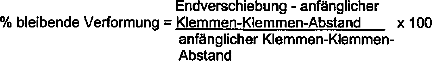
Dehnungs-Stop-TestStrain-stop test
Der hier angewendete Ausdruck ”Dehnungs-Stop-Test” oder ”STS-Test” bezieht sich auf das Verhältnis, das bestimmt wurde aus der Differenz zwischen der nicht-gedehnten Dimension eines elastischen Verbundmaterials und der maximal gedehnten Dimension eines elastischen Verbundmaterials nach dem Anlegen einer spezifischen Dehnungskraft und durch Dividieren dieser Differenz durch die nicht-gedehnte Dimension des elastischen Verbundmaterials. Wenn das Dehnungs-Stop-Verhältnis in% ausgedrückt ist, wird dieses Verhältnis mit 100 multipliziert. So weist beispielsweise ein elastisches Verbundmaterial mit einer nicht-gedehnten Länge von 12,7 cm (5 inches) und einer maximal gedehnten Länge von 25,4 cm (10 inches) beim Anlegen einer Kraft von 2000 g ein Dehnungs-Stop-Verhältnis (bei 2000 g) von 100% auf.The term "strain stop test" or "STS test" as used herein refers to the ratio determined from the difference between the unstretched dimension of a composite elastic material and the maximum stretched dimension of a composite elastic material after application of a specific elongation force and by dividing this difference by the non-stretched dimension of the elastic composite material. If the stretch-stop ratio is expressed in%, this ratio is multiplied by 100. For example, an elastic composite having a non-stretched length of 5 inches and a maximum stretch of 25.4 cm (10 inches) upon application of force of 2000 grams has a stretch-stop ratio 2000 g) of 100%.
Das Dehnungs-Stop-Verhältnis kann auch als ”maximale nicht-zerstörende Dehnung” bezeichnet werden. Wenn nichts anderes angegeben ist, sind hier die Dehnungs-Stop-Werte bei einer Belastung von 2000 g angegeben. In dem Dehnungs- oder Verstreckungs-Stop-Test wurde eine Probe mit der größeren Dimension in der Maschinenlaufrichtung in die Sintech-Vorrichtung eingespannt unter Verwendung eines Abstandes von 5 cm zwischen den Klemmen. Die Probe wurde dann bis zu einer Stop-Belastung von 2000 g mit einer Kreuzkopf-Geschwindigkeit von etwa 50,8 cm/min (20 inches/min) gedehnt (verstreckt).The stretch-stop ratio may also be referred to as "maximum non-destructive stretch". Unless otherwise indicated, the strain-stop values are given here at a load of 2000 g. In the stretch or draw stop test, a larger dimension sample in the machine direction was clamped into the Sintech fixture using a 5 cm gap between the clamps. The sample was then stretched (stretched) to a 2000 g stop load with a crosshead speed of about 50.8 cm / min (20 inches / min).
Cyclischer TestCyclic test
Es wurde ein cyclischer Test durchgeführt unter Verwendung des Computer-g estützten Sintech 1/S-Materialtest-Systems, wie es vorstehend beschrieben wurde. Bei dem Testcyclus wurde ein Material bis zu einer festgelegten Dehnung entsprechend 100% der Dehnung, wie vorstehend beschrieben, 10 mal (10 Cyclen) gedehnt und auf seine ursprüngliche Dimension wieder zurückkehren gelassen, falls dies der Fall war. Die Hysterese in % war der Energieverlust zwischen den Dehnungs- und Kontraktionsphasen in jedem Cyclus. Das heißt mit anderen Worten, die Hysterese in % war wie folgt: 
Abtastelektronenmikroskopie (SEM)Scanning Electron Microscopy (SEM)
Zur Herstellung eines 300 Å dicken Überzugs wurden die Proben in einer Balzer-Minibeschichtungs-Einrichtung in Gegenwart von Argon bei 0,1 mbar und 35 mA 3 min lang bei 135 Volt mit Gold bespritzt. Dann wurden Bilder aufgenommen unter Verwendung eines Hitachi S-4500-Feldemissions-Abtastelektronenmikroskops bei einer Beschleunigungsspannung von 3 kV, einem Werkstück-Abstand von 22 mm und einer Vergrößerung von 40-fach.To prepare a 300 Å thick coating, the samples were spattered with gold in a Balzer mini-coater in the presence of argon at 0.1 mbar and 35 mA for 3 minutes at 135 volts. Then, images were taken using a Hitachi S-4500 field emission scanning electron microscope at an acceleration voltage of 3 kV, a workpiece pitch of 22 mm, and a magnification of 40 times.
Optische Mikroskopie (OM)Optical microscopy (OM)
Die Proben wurden mit Rutheniumtetroxid(RuO4)-Dämpfen angefärbt, um die elastomeren kontinuierlichen Filamente selektiv anzufärben. Die digital transmittierten Lichtbilder wurden direkt erhalten in dem PGT-Bilderzeugungs-System des M420-instruments. Die Anzahl der zerbrochenen (zerrissenen) Filamente pro Einheitsfläche wurde bestimmt unter Ausnutzung des Merkmal-Auszählungsvermögens und durch Dividieren durch die gemessene Fläche. Dieses Verfahren verhinderte jede Notwendigkeit zur Herstellung einer Probe, die anderweitig den Filamentbruch verursachen könnte.The samples were stained with ruthenium tetroxide (RuO 4 ) vapors to selectively stain the elastomeric continuous filaments. The digitally transmitted images were obtained directly in the PGT imaging system of the M420 instrument. The number of broken (torn) filaments per unit area was determined by taking advantage of feature countability and by Divide by the measured area. This method prevented any need to prepare a sample that could otherwise cause filament breakage.
Beispiele 1 bis 2 und Vergleichsbeispiele A bis CExamples 1 to 2 and Comparative Examples A to C.
Alle Proben dieses Tests wurden durchgeführt unter Verwendung einer elastischen kontinuierlichen Filamentschicht aus dem elastomeren (Polystyrol/-Poly(ethylenpropylen)/Polystyrol/Poly(ethylen-propylen))-Block-Copolymer Kraton® G-2760 mit einem Durchmesser in dem Bereich von 0,0508 bis 0,0762 cm (0,020–0,030 inches). Die elastomere Meltblown-Faser wurde auf die kontinuierlichen Filamente durch Meltblowing aufgebracht zur Herstellung einer elastischen Faserbahn mit einem Basisgewicht, wie in der Tabelle 1 angegeben, wobei die elastomere Meltblown-Faser ebenfalls hergestellt wurde aus dem elastomeren Block-Copolymer Kraton® G-2760. Außerdem wurde eine kräuselbare Schicht mit einem Basisgewicht von 13,6 g/m2 (0,4 osy) aus einer weißen Spunbond-Nonwoven-Bahn, hergestellt aus Polypropylen, erhältlich von der Firma Kimberly-Clark, mit jeder Seite der elastischen Faserbahn verbunden. Die Schichten wurden aufeinanderlaminiert unter Erzielung eines Gesamt-Basisgewichtes und Bindungsmusters, wie sie in der Tabelle 1 angegeben sind. Für die elastischen Verbundmaterialien, die unter Verwendung der erfindungsgemäßen gemusterten Nichtbindungs(PUB)-Kalanderwalzen hergestellt wurden, die Proben 1 und 2, betrug der Prozentsatz der gebundenen Fläche 30% des Materials und die vertieften Flächen der Walzen hatten einen Durchmesser von 0,33 cm (0,130 inches) bei einer Tiefe (D) von 0,15 cm (0,060 inches). Das Verstreckungsverhältnis jeder Probe betrug 5-fach. Das heißt mit anderen Worten unter Bezugnahme auf die
Die nachstehenden Proben 1 und 2 wurden erfindungsgemäß hergestellt. Die Probe 2 unterschied sich von der Probe 1 insofern, als sie unter Anwendung eines höheren Bindungsdruckes hergestellt wurde als die Probe 1 – der ausreichend hoch war, so dass er begann, die Material-Eigenschaften zu beeinflussen. Die Vergleichsprobe C war ein Material, das bei den angegebenen Bedingungen gemäß dem Stand der Technik mit glatten Walzen kalandriert worden war. Die Vergleichsproben A und B waren Materialien, die unter den angegebenen Bedingungen gemäß dem Stand der Technik mit gemusterten Walzen kalandriert worden waren. In der Tabelle 1 wurde das Dehnungs-Stop-Verhältnis für die verschiedenen Proben bestimmt. In dem Dehnungs-Stop-Test ist ein Wert von ~400% etwa der maximal erzielbare Wert, weil dieser Wert den Grad angibt, in dem die elastische Faserbahn während des Laminierungsverfahrens gedehnt wird. In den gemusterten Walzen-Proben, den Vergleichsproben A und B, wurden STS-Werte von 219% bzw. 200% gefunden. Wenn der gleiche Proben-Typ mit glatten Walzen kalandriert wurde, nahm der STS-Wert auf 170% ab. Wenn die erfindungsgemäßen Proben getestet wurden, wurden STS-Werte von 210% und 198% gefunden, so dass die vorher erzielbaren Werte (beim Kalandrieren mit gemusterten Walzen) wieder erreicht wurden.The following samples 1 and 2 were prepared according to the invention. Sample 2 differed from Sample 1 in that it was made using a higher bond pressure than Sample 1 - which was sufficiently high that it began to affect material properties. Comparative sample C was a material which had been calendered under the conditions given in the prior art smooth roll technique. Comparative Samples A and B were materials that had been calendered under the conditions specified in the prior art with patterned rolls. In Table 1, the stretch-stop ratio was determined for the various samples. In the stretch-stop test, a value of ~ 400% is about the maximum achievable value because this value indicates the degree to which the elastic fibrous web is stretched during the lamination process. In the patterned roll samples, Comparative Samples A and B, STS values of 219% and 200%, respectively, were found. When the same smooth-roll type sample was calendered, the STS value decreased to 170%. When the samples of this invention were tested, STS values of 210% and 198% were found so that the previously achievable values (calendering with patterned rolls) were regained.
Außerdem wurde die Höchstbelastung pro Gewicht des elastischen Materials in den erfindungsgemäßen Materialien tatsächlich verbessert. Wiederum wurden für die Vergleichsproben A und B Festigkeitswerte von 29,80 und 24,00 g/(g/m2) gemessen. Wenn die Proben mit glatten Walzen kalandriert wurden, wie in der Vergleichsprobe C, wurde eine deutliche Verbesserung der Festigkeit gefunden von 36,90 g/(g/m2), größtenteils zurückzuführen auf die Tatsache, dass die kontinuierliche Filamentschicht nicht zerrissen oder beschädigt war, wie dies der Fall ist beim Kalandrieren mit gemusterten Walzen. Für die erfindungsgemäßen Proben wurde eine überraschende Verbesserung gegenüber den mit gemusterten und glatten Walzen kalandrierten Proben gefunden mit 38,70 g/(g/m2) (was zu vergleichen ist mit den bei 0,17 MPa (25 psi) kalandrierten Proben) bzw. 35,70 g/(g/m2). Tabelle 1 – physikalische Eigenschaften
In der nachstehenden Tabelle 2 wurde die Dimensionsbeständigkeit in Farm der Spannungsrelaxation bei den vorstehend beschriebenen Proben unter Anwendung des vorstehend beschriebenen Testverfahrens getestet. Der Test wurde durchgeführt für eine Dauer von 6 h bei einer Temperatur in der Nähe von Körpertemperatur (37,8°C = 100°F). Geringe Änderungen des Gefälles sind signifikant, weil das Gefälle für diese elastischen Materialien nicht linear ist. In der Probe 2, dem Material, das einem höheren Bindungsdruck ausgesetzt worden war, war die Spannungsrelaxation nicht gut. Aus diesem Grund wird angenommen, dass übermäßig hohe Bindungsdrucke die erfindungsgemäßen elastischen Verbundmaterial in nachteiliger Weise beeinflussen können. Im Vergleich zu der Vergleichsprobe B ergibt sich, dass der höhere Bindungsdruck beim Verbinden mit einer gemusterten Walze das elastische Verbundmaterial nicht in entsprechender Weise nachteilig beeinflusste.In Table 2 below, the dimensional stability in the stress relaxation farm was tested on the samples described above using the test method described above. The test was conducted for a period of 6 hours at a temperature near body temperature (37.8 ° C = 100 ° F). Small changes in slope are significant because the grade for these elastic materials is not linear. In Sample 2, the material which had been subjected to higher bond pressure, stress relaxation was not good. For this reason, it is believed that excessively high bonding pressures may adversely affect the composite elastic materials of the present invention. Compared to Comparative Sample B, it is found that the higher bond pressure when bonded to a patterned roll did not adversely affect the composite elastic material in a corresponding manner.
Aus den unter Anwendung eines Verbindungsdruckes von 0,17 Mpa (25 psi) hergestellten Proben ist zu ersehen, dass für Materialien, die unter Anwendung der gemusterten Walzen-Kalandrierung hergestellt wurden (Vergleichsprobe A) der Belastungsverlust mit 58% hoch ist. Bei dem unter Anwendung des Glattwalzen-Kalandrierens hergestellten Material (Vergleichsprobe C) war der Belastungs-Verlust eindeutig verbessert gegenüber der Vergleichsprobe A mit 49%. Bei der erfindungsgemäß hergestellten Probe, der Probe 1, ist der Belastungs-Verlust vergleichbar mit demjenigen bei der Vergleichsprobe C mit 51% und deutlich verbessert gegenüber der Vergleichsprobe A. Bei den erfindungsgemäß hergestellten Proben war deshalb die Dimensionsbeständigkeit nicht verschlechtert gegenüber den mit einer glatten Walze kalandrierten Materialien und sie war eindeutig verbessert gegenüber den mit einer gemusterten Walze kalandrierten Materialien. Tabelle 2 – Spannungsrelaxation
In der nachstehenden Tabelle 3 sind die Daten angegeben, die resultieren aus dem Test des ”stoffartigen” Aussehens des erfindungsgemäßen Materials, verglichen mit den Vergleichsbeispielen. Die Probe 2 und die Vergleichsprobe B, die Materialien, die unter Anwendung eines höheren Bindungsdruckes gebunden wurden, wurden in bezug auf diese Eigenschaften nicht getestet (N/T), weil die Spannungsrelaxations-Eigenschaften aus der obigen Tabelle 2 anzeigen, dass für die Vergleichsprobe B das Becherzerknüllungs- und Drapierungs-Steifheitsverhalten ähnlich sein würden wie in der Vergleichsprobe A. Außerdem zeigten die Spannungsrelaxations-Eigenschaften für die Probe 2 nicht an, dass attraktive Becherzerknüllungs- und Drapierungs-Steifheitswerte erzielt werden würden. Für die Becherzerknüllung und die Steifheit gilt, dass die Probe um so weicher und um so mehr ”stoffähnlich” ist je niedriger der Wert ist.Table 3 below gives the data resulting from the "fabric-like" appearance test of the invention material compared to the comparative examples. Sample 2 and Comparative Sample B, the materials bonded using a higher bond pressure, were not tested for these properties (N / T) because the stress relaxation properties from Table 2 above indicate that for the comparative sample B would be similar to cup crumpling and drape stiffness behavior as in Comparative Sample A. Additionally, the stress relaxation properties for Sample 2 did not indicate that attractive cup crumpling and drape stiffness values would be achieved. For cup crumpling and stiffness, the lower the value, the softer and the more "cloth-like" the sample is.
Für das erfindungsgemäße Beispiel, die Probe 1, wurden Verbesserungen sowohl in bezug auf die Becherzerknüllungsenerige als auch in bezug auf die Drapierungssteifheit gefunden, verglichen mit den Vergleichsproben A und C, was bedeutet, dass das Material verbesserte Qualitäten in bezug auf das stoffartige Aussehen hatte. Tabelle 3 – Becherzerknüllung- und Drapierungssteifheit
In den nachstehenden Tabellen 4 und 5 wurden die Proben Tests zur Bestimmung der bleibenden Verformung und der Hysterese unterworfen. Diese Daten zeigen, dass bei diesen Materialien weder die bleibende Verformung noch die Hysterese durch das erfindungsgemäße Verfahren negativ beeinflusst wurden. Tabelle 4 – % bleibende Verformung bei der angegebenen Dehnung in % bei Körpertemperatur
In der nachstehenden Tabelle 6 wurde die inhärente Latenz (Eigenlatenz) in der Maschinenlaufrichtung (MD) als Funktion des Prozentsatzes der Schrumpfung bestimmt. Jede der Proben wurde auf ähnliche Weise in einer Richtung quer zur Maschinenlaufrichtung (CD) getestet, da jedoch keine signifikante Schrumpfung gefunden wurde, sind die Daten nachstehend nicht wiedergegeben. Zur Bestimmung des Prozentsatzes der Schrumpfung wurden die Materialien für eine Zeitspanne von etwa 2 bis 3 Tage liegen gelassen, bis die Proben im wesentlichen flach waren. Das relaxierte Material wurde dann zu 7,62 cm × 17,78 cm (3 inch × 7 inch) großen Proben zugeschnitten. Die Proben wurden danach flach in einen Vakuumofen mit einer Temperatur von etwa 71°C (159,8°F) gelegt für eine Zeitspanne von 30 s. Die Endlänge wurde gemessen und der Prozentsatz der Schrumpfung wurde errechnet wie in der nachstehenden Tabelle angegeben. Jeder der nachstehenden Werte stellt den Durchschnittswert aus 5 Teststücken pro Probe dar.In Table 6 below, the intrinsic latency in the machine direction (MD) was determined as a function of the percentage of shrinkage. Each of the samples was similarly tested in a cross-machine direction (CD) direction, but since no significant shrinkage was found, the data is not shown below. To determine the percentage of shrinkage, the materials were left for a period of about 2 to 3 days until the samples were substantially flat. The relaxed material was then cut into 7,62 cm by 17,78 cm (3 inch by 7 inch) sized samples. The samples were then placed flat in a vacuum oven at a temperature of about 71 ° C (159.8 ° F) for a period of 30 seconds. The final length was measured and the percentage of shrinkage was calculated as shown in the table below. Each of the values below represents the average of 5 test pieces per sample.
Wie aus den Daten ersichtlich, ist die Eigenlatenz der erfindungsgemäßen Probe, der Probe 1, im wesentlichen zurückgekehrt zu derjenigen der mit einer gemusterten Walze kalandrierten Probe, der Vergleichsprobe A. Die Eigenlatenz ist somit zu einem besser steuerbaren Wert zurückgekehrt. Außerdem ist es zur Einstellung der Eigenlatenz, falls dies erwünscht ist, durch einfache Erhöhung der gebundenen Fläche möglich, den gwünschten Wert zu erreichen. Tabelle 6 – Eigenlatenz
Die vorliegende Erfindung wurde zwar vorstehend in Verbindung mit bestimmten bevorzugten Ausführungsformen beschrieben, es ist jedoch klar, dass der Gegenstand der Erfindung nicht auf diese spezifischen Ausführungsformen beschränkt ist. Der Gegenstand der Erfindung umfasst vielmehr alle Alternativen, Modifikationen und Äquivalente, die innerhalb des Bereiches der nachstehenden Patentansprüche liegen.While the present invention has been described above in connection with certain preferred embodiments, it will be understood that the subject matter of the invention is not limited to these specific embodiments. Rather, the subject of the invention includes all alternatives, modifications, and equivalents, which are within the scope of the following claims.
Claims (23)
Applications Claiming Priority (5)
| Application Number | Priority Date | Filing Date | Title |
|---|---|---|---|
| US12760899P | 1999-03-31 | 1999-03-31 | |
| US60/127,608 | 1999-03-31 | ||
| US09/292,634 US6387471B1 (en) | 1999-03-31 | 1999-04-15 | Creep resistant composite elastic material with improved aesthetics, dimensional stability and inherent latency and method of producing same |
| US09/292,634 | 1999-04-15 | ||
| PCT/US2000/008804 WO2000058541A1 (en) | 1999-03-31 | 2000-03-31 | A creep resistant composite elastic material and method of producing same |
Publications (2)
| Publication Number | Publication Date |
|---|---|
| DE10084227T1 DE10084227T1 (en) | 2002-02-28 |
| DE10084227B3 true DE10084227B3 (en) | 2013-01-03 |
Family
ID=26825783
Family Applications (1)
| Application Number | Title | Priority Date | Filing Date |
|---|---|---|---|
| DE10084227T Expired - Fee Related DE10084227B3 (en) | 1999-03-31 | 2000-03-31 | Creep-resistant elastic composite material and method for its production |
Country Status (8)
| Country | Link |
|---|---|
| US (1) | US6387471B1 (en) |
| KR (1) | KR100752900B1 (en) |
| AR (1) | AR023223A1 (en) |
| AU (1) | AU3932900A (en) |
| BR (1) | BR0009318B1 (en) |
| DE (1) | DE10084227B3 (en) |
| GB (1) | GB2363757B (en) |
| WO (1) | WO2000058541A1 (en) |
Cited By (1)
| Publication number | Priority date | Publication date | Assignee | Title |
|---|---|---|---|---|
| US8652976B2 (en) | 2005-06-01 | 2014-02-18 | Carl Freudenberg Kg | Fixable nonwoven interlining material used in the textile industry |
Families Citing this family (41)
| Publication number | Priority date | Publication date | Assignee | Title |
|---|---|---|---|---|
| US20010018979A1 (en) * | 1997-12-10 | 2001-09-06 | Lucent Technologies Inc. | Device and method of forming a unitary electrically shielded panel |
| US6939334B2 (en) † | 2001-12-19 | 2005-09-06 | Kimberly-Clark Worldwide, Inc. | Three dimensional profiling of an elastic hot melt pressure sensitive adhesive to provide areas of differential tension |
| US7837665B2 (en) * | 2002-10-01 | 2010-11-23 | Kimberly-Clark Worldwide, Inc. | Three-piece disposable undergarment with folded crotch member |
| US8043273B2 (en) * | 2002-12-19 | 2011-10-25 | Kimberly-Clark Worldwide, Inc. | Disposable undergarment with a stretchable absorbent insert and method for the use thereof |
| US7220335B2 (en) * | 2002-10-01 | 2007-05-22 | Kimberly-Clark Worldwide, Inc. | Three-piece disposable undergarment with stretchable crotch member and method for the manufacture thereof |
| US6979380B2 (en) | 2002-10-01 | 2005-12-27 | Kimberly-Clark Worldwide, Inc. | Three-piece disposable undergarment and method for the manufacture thereof |
| US7749211B2 (en) * | 2002-10-18 | 2010-07-06 | Kimberly-Clark Worldwide, Inc. | Body conforming absorbent garment and methods for the use and manufacture thereof |
| US7994079B2 (en) * | 2002-12-17 | 2011-08-09 | Kimberly-Clark Worldwide, Inc. | Meltblown scrubbing product |
| US20040111817A1 (en) * | 2002-12-17 | 2004-06-17 | Kimberly-Clark Worldwide, Inc. | Disposable scrubbing product |
| JP4489346B2 (en) * | 2002-12-17 | 2010-06-23 | シャープ株式会社 | Liquid crystal display |
| US7476447B2 (en) | 2002-12-31 | 2009-01-13 | Kimberly-Clark Worldwide, Inc. | Elastomeric materials |
| US7919666B2 (en) * | 2002-12-31 | 2011-04-05 | Kimberly-Clark Worldwide, Inc. | Personal care articles with fragrance delivery system |
| US6916750B2 (en) | 2003-03-24 | 2005-07-12 | Kimberly-Clark Worldwide, Inc. | High performance elastic laminates made from high molecular weight styrenic tetrablock copolymer |
| US20040210205A1 (en) * | 2003-04-15 | 2004-10-21 | Kimberly-Clark Worldwide, Inc. | Disposable pant-like undergarment |
| US7604624B2 (en) * | 2003-05-30 | 2009-10-20 | Kimberly-Clark Worldwide, Inc. | Disposable absorbent article with overlapping absorbent assembly secured to front and back panels |
| US7018369B2 (en) | 2003-05-30 | 2006-03-28 | Kimberly-Clark Worldwide, Inc. | Disposable pant-like undergarment having an elastic band adjacent the waist opening |
| US6846876B1 (en) * | 2003-07-16 | 2005-01-25 | Adherent Laboratories, Inc. | Low odor, light color, disposable article construction adhesive |
| US20050136771A1 (en) * | 2003-12-22 | 2005-06-23 | Hendon Nathan P. | Elastic laminate with directional bonding and method of manufacture |
| US20050136772A1 (en) * | 2003-12-23 | 2005-06-23 | Kimberly-Clark Worldwide, Inc. | Composite structures containing tissue webs and other nonwovens |
| US8562580B2 (en) | 2004-04-30 | 2013-10-22 | Kimberly-Clark Worldwide, Inc. | Selective modification of a nonwoven surface |
| US7373698B2 (en) * | 2004-06-24 | 2008-05-20 | Tyco Healthcare Retail Services Ag | Closure tabs for absorbent articles |
| US20060135026A1 (en) * | 2004-12-22 | 2006-06-22 | Kimberly-Clark Worldwide, Inc. | Composite cleaning products having shape resilient layer |
| US7612001B2 (en) * | 2004-12-22 | 2009-11-03 | Kimberly-Clark Worldwide, Inc. | High performance elastic materials made using styrene block copolymers and mixtures |
| US7910658B2 (en) | 2005-03-17 | 2011-03-22 | Dow Global Technologies Llc | Compositions of ethylene/α-olefin multi-block interpolymer for elastic films and laminates |
| US20060228969A1 (en) * | 2005-04-07 | 2006-10-12 | Erdman Edward P | Elastic laminate |
| US7384491B2 (en) * | 2005-09-01 | 2008-06-10 | Kimberly-Clark Worldwide, Inc. | Apparatus and methods for making crosslinked elastic laminates |
| US20070298262A1 (en) * | 2006-06-22 | 2007-12-27 | Tredegar Film Products Corporation | Elastic film exhibiting low tensile force properties in the machine direction |
| US7910794B2 (en) | 2007-03-05 | 2011-03-22 | Adherent Laboratories, Inc. | Disposable diaper construction and adhesive |
| SG187481A1 (en) | 2008-01-24 | 2013-02-28 | Clopay Plastic Prod Co | Elastomeric materials |
| US20120149262A1 (en) * | 2008-03-12 | 2012-06-14 | Curt G. Joa, Inc. | Registered stretch laminate and methods for forming a registered stretch laminate |
| US8062453B2 (en) * | 2008-04-02 | 2011-11-22 | Bae Systems Land & Armaments, L.P. | Method for quasi-instantaneous polymerization of filament wound composite materials |
| JP5385556B2 (en) * | 2008-06-25 | 2014-01-08 | ユニ・チャーム株式会社 | Method for manufacturing absorbent article |
| US8171972B2 (en) | 2009-01-30 | 2012-05-08 | The Procter & Gamble Company | Strip guide for high-speed continuous application of a strip material to a moving sheet-like substrate material at laterally shifting locations |
| US20100193135A1 (en) * | 2009-01-30 | 2010-08-05 | Joseph Allen Eckstein | System and Method for High-Speed Continuous Application of a Strip Material to a Moving Sheet-Like Substrate Material at Laterally Shifting Locations |
| US8182627B2 (en) * | 2009-01-30 | 2012-05-22 | The Procter & Gamble Company | Method for high-speed continuous application of a strip material to a substrate along an application path on the substrate |
| US20100193138A1 (en) * | 2009-01-30 | 2010-08-05 | Joseph Allen Eckstein | System for High-Speed Continuous Application of a Strip Material to a Moving Sheet-Like Substrate Material at Laterally Shifting Locations |
| US8945324B2 (en) | 2011-04-04 | 2015-02-03 | Kimberly-Clark Worldwide, Inc. | Process for making elastomeric absorbent garments to reduce absorbent bunching |
| WO2014004453A1 (en) | 2012-06-29 | 2014-01-03 | The Procter & Gamble Company | System and method for high-speed continuous application of a strip material to a moving sheet-like substrate material |
| KR101735309B1 (en) * | 2012-12-21 | 2017-05-15 | 에스체아 히기에너 프로덕츠 악티에볼라그 | Elastic laminate and process for the manufacture of elastic laminate |
| US10369246B2 (en) * | 2013-06-14 | 2019-08-06 | Krp U.S., Llc | Absorbent articles having pockets and related methods therefor |
| FI20165904L (en) * | 2016-11-28 | 2018-05-29 | Teknologian Tutkimuskeskus Vtt Oy | Foam fiber elastomeric materials and their manufacturing |
Citations (5)
| Publication number | Priority date | Publication date | Assignee | Title |
|---|---|---|---|---|
| US4333979A (en) * | 1980-08-18 | 1982-06-08 | Kimberly-Clark Corporation | Soft, bulky, lightweight nonwoven web and method of producing; the web has both fused spot bonds and patterned embossments |
| EP0548609A1 (en) * | 1991-12-09 | 1993-06-30 | Kimberly-Clark Corporation | A composite elastic material including an anisotropic elastic fibrous web and process to make the same |
| WO1997034037A1 (en) * | 1996-03-14 | 1997-09-18 | Kimberly-Clark Worldwide, Inc. | Nonwoven fabric laminate with good conformability |
| WO1998029251A1 (en) * | 1996-12-30 | 1998-07-09 | Kimberly-Clark Worldwide, Inc. | Improved composite elastic material and process for producing the same |
| DE19725749A1 (en) * | 1995-12-19 | 1998-12-24 | Hcd Gmbh | Bulking treatment of non-woven |
Family Cites Families (215)
| Publication number | Priority date | Publication date | Assignee | Title |
|---|---|---|---|---|
| US2206761A (en) | 1938-10-17 | 1940-07-02 | Bergstein Robert Morris | Machine and method for package closure |
| US2266761A (en) | 1940-04-16 | 1941-12-23 | American Reenforced Paper Co | Fibrous sheet |
| NL70708C (en) | 1941-03-01 | |||
| US2483405A (en) | 1943-11-20 | 1949-10-04 | American Viscose Corp | Fibrous products and textiles produced therewith |
| US2464301A (en) | 1943-12-18 | 1949-03-15 | American Viscose Corp | Textile fibrous product |
| BE534424A (en) | 1953-12-24 | |||
| DE1161007B (en) | 1955-12-29 | 1964-01-09 | E. I. du Pont de Nemours & Company, Wilmington, Del. (V. St. A.) | Manufacture of synthetic resin films or threads |
| US3186893A (en) | 1961-06-08 | 1965-06-01 | Plastic Textile Access Ltd | Laminated materials including plastic netting |
| DE1282590C2 (en) | 1963-10-25 | 1975-02-13 | Lutravil Spinnvlies GmbH & Co., 8750 Kaiserslautern | APPARATUS FOR THE MANUFACTURING OF ANNEALED FIBERS FROM ENDLESS POLYMERIC FIBERS |
| US3391048A (en) | 1964-01-10 | 1968-07-02 | Eastman Kodak Co | Entangled nonwoven web product from parallel laid filamentary tows |
| US3449187A (en) | 1964-12-08 | 1969-06-10 | Bobkowicz E | Method and apparatus for making nonwoven fabrics |
| US3371668A (en) | 1965-04-14 | 1968-03-05 | Johnson & Johnson | Sanitary napkin |
| US3468748A (en) | 1965-04-14 | 1969-09-23 | Johnson & Johnson | Nonwoven fabric with machine direction elasticity |
| US3575782A (en) | 1967-05-19 | 1971-04-20 | Minnesota Mining & Mfg | Elastic shirred web product |
| US3849241A (en) | 1968-12-23 | 1974-11-19 | Exxon Research Engineering Co | Non-woven mats by melt blowing |
| US3978185A (en) | 1968-12-23 | 1976-08-31 | Exxon Research And Engineering Company | Melt blowing process |
| US3616129A (en) | 1969-04-07 | 1971-10-26 | Kimberly Clark Co | Longitudinally stretchable nonwoven material |
| US3669823A (en) | 1969-06-04 | 1972-06-13 | Curlator Corp | Non-woven web |
| US3676242A (en) | 1969-08-13 | 1972-07-11 | Exxon Research Engineering Co | Method of making a nonwoven polymer laminate |
| DE2048006B2 (en) | 1969-10-01 | 1980-10-30 | Asahi Kasei Kogyo K.K., Osaka (Japan) | Method and device for producing a wide nonwoven web |
| US3673026A (en) | 1970-01-12 | 1972-06-27 | Int Paper Co | Method for the manufacture of laminated fabrics |
| US3836416A (en) | 1970-01-29 | 1974-09-17 | Alta Ind | Non woven thermoplastic fabric |
| US3629047A (en) | 1970-02-02 | 1971-12-21 | Hercules Inc | Nonwoven fabric |
| CA948388A (en) * | 1970-02-27 | 1974-06-04 | Paul B. Hansen | Pattern bonded continuous filament web |
| US3752613A (en) | 1970-12-08 | 1973-08-14 | Celanese Corp | Apparatus for producing spray spun nonwoven sheets |
| US3689342A (en) | 1970-12-08 | 1972-09-05 | Celanese Corp | Method for producing spray-spun nonwoven sheets |
| US3873255A (en) | 1971-01-27 | 1975-03-25 | Johnson & Johnson | Apparatus for producing nonwoven fabric |
| US3890184A (en) | 1971-07-16 | 1975-06-17 | Exxon Research Engineering Co | Method of making extruded rib battery separators |
| US3773590A (en) | 1971-07-16 | 1973-11-20 | Exxon Co | Method of forming ribbed battery separators |
| GB1425116A (en) | 1972-03-20 | 1976-02-18 | Du Pont | Non-woven fabrics and method of making same |
| US3806289A (en) | 1972-04-05 | 1974-04-23 | Kimberly Clark Co | Apparatus for producing strong and highly opaque random fibrous webs |
| GB1453447A (en) | 1972-09-06 | 1976-10-20 | Kimberly Clark Co | Nonwoven thermoplastic fabric |
| US3912567A (en) | 1973-05-14 | 1975-10-14 | Kimberly Clark Co | Stabilized nonwoven web and method of preparation |
| US3949130A (en) | 1974-01-04 | 1976-04-06 | Tuff Spun Products, Inc. | Spun bonded fabric, and articles made therefrom |
| US4209563A (en) | 1975-06-06 | 1980-06-24 | The Procter & Gamble Company | Method for making random laid bonded continuous filament cloth |
| US4107364A (en) | 1975-06-06 | 1978-08-15 | The Procter & Gamble Company | Random laid bonded continuous filament cloth |
| US4211807A (en) | 1975-08-08 | 1980-07-08 | Polymer Processing Research Institute Ltd. | Reinforced non-woven fabrics and method of making same |
| US4013816A (en) | 1975-11-20 | 1977-03-22 | Draper Products, Inc. | Stretchable spun-bonded polyolefin web |
| US4090385A (en) | 1977-01-26 | 1978-05-23 | Bird Machine Company, Inc. | Material treating apparatus |
| JPS6056825B2 (en) | 1978-05-01 | 1985-12-12 | 東亜燃料工業株式会社 | Manufacturing method of nonwoven fabric |
| US4259220A (en) | 1978-12-06 | 1981-03-31 | H. B. Fuller Company | Hot melt adhesive for elastic banding |
| US4719261A (en) | 1978-09-22 | 1988-01-12 | H. B. Fuller Company | Hot melt adhesive for elastic banding and method for utlizing the same |
| US4543099A (en) | 1978-12-06 | 1985-09-24 | H. B. Fuller Company | Method for imparting elastic properties to a flexible substrate |
| US4418123A (en) | 1978-12-06 | 1983-11-29 | H. B. Fuller Company | Extrudable self-adhering elastic and method of employing same |
| US4342314A (en) | 1979-03-05 | 1982-08-03 | The Procter & Gamble Company | Resilient plastic web exhibiting fiber-like properties |
| DE2924539C2 (en) | 1979-06-19 | 1983-01-13 | Fa. Carl Freudenberg, 6940 Weinheim | Polyolefin filament spunbond and process for its manufacture |
| US4239578A (en) | 1979-10-16 | 1980-12-16 | Riegel Textile Corporation | Apparatus for inserting elastic strips during the manufacture of elastic leg disposable diapers |
| US4405397A (en) | 1979-10-16 | 1983-09-20 | Riegel Textile Corporation | Process for manufacturing elastic leg disposable diapers |
| US4323534A (en) | 1979-12-17 | 1982-04-06 | The Procter & Gamble Company | Extrusion process for thermoplastic resin composition for fabric fibers with exceptional strength and good elasticity |
| US4303571A (en) | 1980-01-17 | 1981-12-01 | Exxon Research & Engineering Co. | Film-forming thermoplastic elastomeric polymer compositions |
| US4333782A (en) | 1980-02-11 | 1982-06-08 | Johnson & Johnson Baby Products Company | Method of making laminated structures having gathered and ungathered marginal portions |
| US4310594A (en) | 1980-07-01 | 1982-01-12 | Teijin Limited | Composite sheet structure |
| US4302495A (en) | 1980-08-14 | 1981-11-24 | Hercules Incorporated | Nonwoven fabric of netting and thermoplastic polymeric microfibers |
| FR2490079A1 (en) | 1980-09-15 | 1982-03-19 | Boussac Saint Freres Bsf | PROCESS FOR MANUFACTURING CUTTING LAYERS AND CUTTING LAYERS OBTAINED BY CARRYING OUT SAID METHOD |
| US4413623A (en) | 1981-02-17 | 1983-11-08 | Johnson & Johnson Baby Products Company | Laminated structures having gathered and ungathered marginal portions and method of manufacturing the same |
| US4463045A (en) | 1981-03-02 | 1984-07-31 | The Procter & Gamble Company | Macroscopically expanded three-dimensional plastic web exhibiting non-glossy visible surface and cloth-like tactile impression |
| US4432823A (en) | 1981-06-29 | 1984-02-21 | Kimberly Clark Corporation | Method and apparatus for manufacturing elastic leg disposable diapers |
| US4507163A (en) | 1981-08-27 | 1985-03-26 | Johnson & Johnson Baby Products Company | Imparting an inelastic and elastic character to predetermined portions of an elastic web for use in making disposable diapers |
| US4371417A (en) | 1981-10-01 | 1983-02-01 | Kimberly-Clark Corporation | Differentially stretched elastic |
| US4417935A (en) | 1981-10-13 | 1983-11-29 | Paper Converting Machine Company | Method of diaper manufacture |
| JPS58180601A (en) | 1982-04-14 | 1983-10-22 | ユニ・チヤ−ム株式会社 | Disposable diaper and attachment of elastic member thereof |
| US4490427A (en) | 1982-06-14 | 1984-12-25 | Firma Carl Freudenberg | Adhesive webs and their production |
| US4917746A (en) | 1982-06-21 | 1990-04-17 | Kons Hugo L | Apparatus and method for contouring elastic ribbon on disposable garments |
| US4525407A (en) * | 1982-08-27 | 1985-06-25 | Chicopee | Elastic composites |
| US4518451A (en) | 1982-09-02 | 1985-05-21 | Personal Products Company | Embossed panty liner |
| US4774124A (en) | 1982-09-30 | 1988-09-27 | Chicopee | Pattern densified fabric comprising conjugate fibers |
| US4496417A (en) | 1982-11-12 | 1985-01-29 | Adolph Coors Company | Control stretch laminating device |
| US4572752A (en) | 1982-11-12 | 1986-02-25 | Adolph Coors Company | Control stretch laminating device |
| US4440819A (en) | 1982-12-27 | 1984-04-03 | Hughes Aircraft Company | Interconnection of unidirectional fiber arrays with random fiber networks |
| FR2539274A1 (en) | 1983-01-19 | 1984-07-20 | Boussac Saint Freres Bsf | PROCESS FOR MANUFACTURING JET-CUTTING LAYERS AND GUITAR LAYERS OBTAINED |
| FR2542979B1 (en) | 1983-03-25 | 1988-04-22 | Boussac Saint Freres Bsf | PROCESS FOR THE CONTINUOUS MANUFACTURE OF DISPOSABLE PANTY LAYERS AND PANTY LAYERS OBTAINED |
| JPS59199856A (en) | 1983-04-25 | 1984-11-13 | 東レ株式会社 | Nonwoven sheet and production thereof |
| US4552795A (en) | 1983-12-27 | 1985-11-12 | Minnesota Mining And Manufacturing Co. | Inelastic, heat-elasticizable sheet material |
| US4640859A (en) | 1983-12-27 | 1987-02-03 | Minnesota Mining And Manufacturing Company | Inelastic, heat-elasticizable sheet material for diapers |
| US4555811A (en) | 1984-06-13 | 1985-12-03 | Chicopee | Extensible microfine fiber laminate |
| US4546029A (en) | 1984-06-18 | 1985-10-08 | Clopay Corporation | Random embossed matte plastic film |
| US4548859A (en) | 1984-10-12 | 1985-10-22 | The Boeing Company | Breather material and method of coating fabric with silicone rubber |
| SE449820B (en) | 1984-11-28 | 1987-05-25 | Mo Och Domsjoe Ab | DEVICE FOR ADMINISTRATIVE ADMINISTRATION TO AN ELASTIC BAND ON A PLASTIC COVER FOR MANUFACTURING BLOWS |
| US4734311A (en) | 1985-01-16 | 1988-03-29 | Kimberly-Clark Corporation | Elasticized non-woven fabric and method of making the same |
| US4652487A (en) | 1985-07-30 | 1987-03-24 | Kimberly-Clark Corporation | Gathered fibrous nonwoven elastic web |
| US4720415A (en) | 1985-07-30 | 1988-01-19 | Kimberly-Clark Corporation | Composite elastomeric material and process for making the same |
| US4663220A (en) | 1985-07-30 | 1987-05-05 | Kimberly-Clark Corporation | Polyolefin-containing extrudable compositions and methods for their formation into elastomeric products including microfibers |
| US4692371A (en) | 1985-07-30 | 1987-09-08 | Kimberly-Clark Corporation | High temperature method of making elastomeric materials and materials obtained thereby |
| US4657802A (en) | 1985-07-30 | 1987-04-14 | Kimberly-Clark Corporation | Composite nonwoven elastic web |
| US4761198A (en) | 1985-08-12 | 1988-08-02 | National Starch And Chemical Corporation | Use of a thermoplastic elastic adhesive for elastic banding |
| US4683877A (en) | 1985-10-04 | 1987-08-04 | Minnesota Mining And Manufacturing Company | Orthopedic casting article and method |
| US4761322A (en) | 1985-10-07 | 1988-08-02 | Kimberly-Clark Corporation | Laminated fibrous web comprising differentially bonded layers, and method and apparatus for making the same |
| US4606964A (en) * | 1985-11-22 | 1986-08-19 | Kimberly-Clark Corporation | Bulked web composite and method of making the same |
| US4794680A (en) | 1985-12-20 | 1989-01-03 | Union Carbide Corporation | Novel wear-resistant laser-engraved ceramic or metallic carbide surfaces for friction rolls for working elongate members, method for producing same and method for working elongate members using the novel friction roll |
| US4803117A (en) | 1986-03-24 | 1989-02-07 | Kimberly-Clark Corporation | Coformed ethylene-vinyl copolymer elastomeric fibrous webs |
| AU7049687A (en) | 1986-03-24 | 1987-10-01 | Kimberly-Clark Corporation | Ethylene-vinyl copolymers and methods for their formation into elastomeric fibrous products |
| US4863779A (en) | 1986-03-24 | 1989-09-05 | Kimberly-Clark Corporation | Composite elastomeric material |
| US4726807A (en) | 1986-04-10 | 1988-02-23 | Weyerhaeuser Company | Diaper with elastic margins |
| US4908247A (en) | 1986-04-15 | 1990-03-13 | The Procter & Gamble Company | Article including segment which is elastically shirrable after manufacture |
| US4892903A (en) | 1986-07-07 | 1990-01-09 | Shell Oil Company | Elastomeric fibers, structures fashioned therefrom and elastomeric films |
| CH669328A5 (en) | 1986-09-18 | 1989-03-15 | Vitapharm Basel Ag | |
| US4777080A (en) | 1986-10-15 | 1988-10-11 | Kimberly-Clark Corporation | Elastic abrasion resistant laminate |
| US4789699A (en) | 1986-10-15 | 1988-12-06 | Kimberly-Clark Corporation | Ambient temperature bondable elastomeric nonwoven web |
| US4692368A (en) | 1986-10-15 | 1987-09-08 | Kimberly-Clark Corporation | Elastic spunlaced polyester-meltblown polyetherurethane laminate |
| US4801482A (en) | 1986-10-15 | 1989-01-31 | Kimberly-Clark Corporation | Elastic nonwoven pad |
| DE3784619T2 (en) | 1986-10-21 | 1993-06-17 | Mitsui Petrochemical Ind | EXTRUSION NOZZLE FOR MELT BLOWING. |
| US4984584A (en) | 1987-01-16 | 1991-01-15 | Riker Laboratories, Inc. | High elastic modulus bandage |
| US4804577A (en) | 1987-01-27 | 1989-02-14 | Exxon Chemical Patents Inc. | Melt blown nonwoven web from fiber comprising an elastomer |
| US4874447A (en) | 1987-01-27 | 1989-10-17 | Exxon Chemical Patents, Inc. | Melt blown nonwoven web from fiber comprising an elastomer |
| US4735673A (en) | 1987-02-19 | 1988-04-05 | Colgate-Palmolive Company | Machine for fastening stretched pieces of elastic band traversely to a continuously moving sheet |
| EP0281857B1 (en) | 1987-03-07 | 1993-07-21 | H.B. FULLER LICENSING & FINANCING, INC. | Method for securing elastic elements - strands or tapes - on a sheet, and use of this method in making elasticized portions of a web |
| US4906507A (en) | 1987-03-13 | 1990-03-06 | Freudenberg Nonwovens Limited Partnership | Composite adhesive webs and their production |
| US5060349A (en) | 1987-04-02 | 1991-10-29 | Richard R. Walton | Compressive treatment of webs |
| US4968313A (en) | 1987-04-27 | 1990-11-06 | Sabee Reinhardt N | Diaper with waist band elastic |
| US4929492A (en) | 1987-07-24 | 1990-05-29 | Minnesota Mining And Manufacturing Company | Stretchable insulating fabric |
| US4775579A (en) | 1987-11-05 | 1988-10-04 | James River Corporation Of Virginia | Hydroentangled elastic and nonelastic filaments |
| US4891258A (en) | 1987-12-22 | 1990-01-02 | Kimberly-Clark Corporation | Stretchable absorbent composite |
| US5376198A (en) | 1987-12-22 | 1994-12-27 | Kimberly-Clark Corporation | Method for making a stretchable absorbent article |
| US5232777A (en) | 1987-12-23 | 1993-08-03 | Minnesota Mining And Manufacturing Company | Elastic strand construction |
| JP2545260B2 (en) | 1988-02-02 | 1996-10-16 | チッソ株式会社 | Bulky reinforced non-woven fabric |
| EP0327402A3 (en) | 1988-02-05 | 1990-10-10 | Tonen Chemical Corporation | Gas-permeable, waterproof composite sheet |
| EP0330716A3 (en) | 1988-03-02 | 1991-07-03 | Ipf Interpatent + Franchise Aktiengesellschaft | Heat-shirring sheet structure and method and apparatus for its manufacture |
| JP2615189B2 (en) | 1988-03-07 | 1997-05-28 | パラゴン トレード ブランズ インコーポレイテッド | Device for attaching stretched elastic piece to moving web |
| US5000806A (en) | 1988-04-19 | 1991-03-19 | Paper Converting Machine Company | Method and apparatus for applying an elastic strand to a disposable diaper |
| US5296080A (en) | 1988-04-19 | 1994-03-22 | Paper Converting Machine Company | Apparatus for applying an elastic waistband to a disposable diaper |
| US5256231A (en) | 1988-05-13 | 1993-10-26 | Minnesota Mining And Manufacturing Company | Method for making a sheet of loop material |
| US4910064A (en) | 1988-05-25 | 1990-03-20 | Sabee Reinhardt N | Stabilized continuous filament web |
| US4977011A (en) | 1988-09-19 | 1990-12-11 | Weyerhaeuser Company | Disposable elastic structure |
| US5209801A (en) | 1988-09-19 | 1993-05-11 | Weyerhaeuser Company | Method of forming a disposable elastic structure |
| US5514470A (en) | 1988-09-23 | 1996-05-07 | Kimberly-Clark Corporation | Composite elastic necked-bonded material |
| US5226992A (en) * | 1988-09-23 | 1993-07-13 | Kimberly-Clark Corporation | Process for forming a composite elastic necked-bonded material |
| US4981747A (en) | 1988-09-23 | 1991-01-01 | Kimberly-Clark Corporation | Composite elastic material including a reversibly necked material |
| US4900619A (en) | 1988-10-17 | 1990-02-13 | James River Corporation | Translucent housewrap |
| US4995928A (en) | 1988-10-31 | 1991-02-26 | Sabee Reinhardt N | Method and apparatus for forming and transporting elastic ribbons |
| US5360854A (en) | 1988-12-05 | 1994-11-01 | Adhesive Technology, Inc. | Hot melt pressure sensitive adhesive composition and applications |
| US4883549A (en) | 1988-12-06 | 1989-11-28 | Kimberly-Clark Corporation | Method of attaching a composite elastic material to an article |
| US5549964A (en) | 1988-12-27 | 1996-08-27 | Asahi Kasei Kogyo Kabushiki Kaisha | Stretchable nonwoven fabric and method of manufacturing the same |
| US5312500A (en) | 1989-01-27 | 1994-05-17 | Nippon Petrochemicals Co., Ltd. | Non-woven fabric and method and apparatus for making the same |
| US5198281A (en) | 1989-04-17 | 1993-03-30 | Georgia Tech Research Corporation | Non-woven flexible multiply towpreg fabric |
| JPH0611275B2 (en) | 1989-06-29 | 1994-02-16 | ユニ・チャーム株式会社 | Disposable brief manufacturing method |
| KR950004727B1 (en) | 1989-08-08 | 1995-05-06 | 가부시끼가이샤 나까무라세이시쇼 | Thermal Adhesive Sheet |
| US4970259A (en) | 1989-08-16 | 1990-11-13 | Shell Oil Company | Elastomeric film composition |
| US5143774A (en) | 1989-09-01 | 1992-09-01 | Clopay Corporation | Nonwoven fibrous embossed plastic film |
| US5188885A (en) | 1989-09-08 | 1993-02-23 | Kimberly-Clark Corporation | Nonwoven fabric laminates |
| US5073436A (en) | 1989-09-25 | 1991-12-17 | Amoco Corporation | Multi-layer composite nonwoven fabrics |
| US5308345A (en) | 1989-11-28 | 1994-05-03 | John M. Tharpe | System and method for manufacturing disposable diapers having elastic waistband |
| US5116662A (en) | 1989-12-15 | 1992-05-26 | Kimberly-Clark Corporation | Multi-direction stretch composite elastic material |
| US5169706A (en) | 1990-01-10 | 1992-12-08 | Kimberly-Clark Corporation | Low stress relaxation composite elastic material |
| DE4000495C2 (en) | 1990-01-10 | 1994-03-03 | Spohn Verpackungswerke Gmbh & | Method and device for laminating an unstretched film with an stretched film and a multilayer film |
| US5260126A (en) | 1990-01-10 | 1993-11-09 | Kimberly-Clark Corporation | Low stress relaxation elastomeric nonwoven webs and fibers |
| US5681645A (en) * | 1990-03-30 | 1997-10-28 | Kimberly-Clark Corporation | Flat elastomeric nonwoven laminates |
| US5093422A (en) | 1990-04-23 | 1992-03-03 | Shell Oil Company | Low stress relaxation extrudable elastomeric composition |
| CA2050782C (en) | 1990-09-13 | 1997-01-28 | Takamitsu Igaue | Disposable garments and method for attachment of elastic members around leg-holes thereof |
| US5100435A (en) | 1990-12-04 | 1992-03-31 | Kimberly-Clark Corporation | Meltblown nonwoven webs made from epoxy/pcl blends |
| US5219633A (en) | 1991-03-20 | 1993-06-15 | Tuff Spun Fabrics, Inc. | Composite fabrics comprising continuous filaments locked in place by intermingled melt blown fibers and methods and apparatus for making |
| WO1992016366A1 (en) | 1991-03-20 | 1992-10-01 | Sabee Reinhardt N | Elasticized fabric with continuous filaments and method of forming |
| US5200246A (en) | 1991-03-20 | 1993-04-06 | Tuff Spun Fabrics, Inc. | Composite fabrics comprising continuous filaments locked in place by intermingled melt blown fibers and methods and apparatus for making |
| EP0585354B1 (en) | 1991-05-20 | 1997-12-29 | The Procter & Gamble Company | Multilayer female component for refastenable fastening device |
| US5229186A (en) | 1991-07-08 | 1993-07-20 | Tredegar Industries, Inc. | Deep embossed plastic film |
| DE4125151C2 (en) | 1991-07-30 | 1994-09-29 | Freudenberg Carl Fa | Non-woven laminate with high specific volume and good strength |
| US5169712A (en) | 1991-08-23 | 1992-12-08 | Amoco Corporation | Porous film composites |
| KR930006226A (en) | 1991-09-30 | 1993-04-21 | 원본미기재 | Elastic composite nonwoven fabrics and methods of making the same |
| US5484645A (en) | 1991-10-30 | 1996-01-16 | Fiberweb North America, Inc. | Composite nonwoven fabric and articles produced therefrom |
| US5415925A (en) | 1992-06-10 | 1995-05-16 | Fiberweb North America, Inc. | Gamma structure composite nonwoven fabric comprising at least two nonwoven webs adhesively bonded by a lightweight adhesive web |
| US5229191A (en) | 1991-11-20 | 1993-07-20 | Fiberweb North America, Inc. | Composite nonwoven fabrics and method of making same |
| US5393599A (en) | 1992-01-24 | 1995-02-28 | Fiberweb North America, Inc. | Composite nonwoven fabrics |
| US5334446A (en) | 1992-01-24 | 1994-08-02 | Fiberweb North America, Inc. | Composite elastic nonwoven fabric |
| US5470639A (en) | 1992-02-03 | 1995-11-28 | Fiberweb North America, Inc. | Elastic nonwoven webs and method of making same |
| DE69310406T2 (en) | 1992-02-13 | 1997-09-18 | Japan Absorbent Technology Ins | Compound elastic sheet for hygiene articles, their manufacturing process and their use |
| US5366793A (en) | 1992-04-07 | 1994-11-22 | Kimberly Clark Co | Anisotropic nonwoven fibrous web |
| US5296289A (en) * | 1992-04-29 | 1994-03-22 | Collins Loren M | Stretchable spun bonded nonwoven web and method |
| US5405682A (en) | 1992-08-26 | 1995-04-11 | Kimberly Clark Corporation | Nonwoven fabric made with multicomponent polymeric strands including a blend of polyolefin and elastomeric thermoplastic material |
| US5259902A (en) | 1992-09-04 | 1993-11-09 | The Procter & Gamble Company | Method for continuously attaching tensioned elastic material to an absorbent article |
| US5275676A (en) | 1992-09-18 | 1994-01-04 | Kimberly-Clark Corporation | Method and apparatus for applying a curved elastic to a moving web |
| US5334437A (en) | 1992-09-23 | 1994-08-02 | E. I. Du Pont De Nemours And Company | Spunlaced fabric comprising a nonwoven Batt hydraulically entangled with a warp-like array of composite elastic yarns |
| DE4238541C2 (en) * | 1992-11-14 | 1999-01-28 | Amoco Fabrics Zweigniederlassu | Method and device for producing an elastic, multilayer material web |
| US5389173A (en) | 1992-12-02 | 1995-02-14 | Paper Converting Machine Company | Apparatus and process for making disposable diaper type products |
| DE4243012C2 (en) | 1992-12-18 | 1997-09-11 | Corovin Gmbh | Multi-layer elastic sheet and method for producing a multi-layer elastic sheet |
| CA2097630A1 (en) | 1992-12-29 | 1994-06-30 | Ann Louise Mccormack | Stretch-pillowed, bulked laminate |
| US5342469A (en) | 1993-01-08 | 1994-08-30 | Poly-Bond, Inc. | Method of making a composite with discontinuous adhesive structure |
| US5399174A (en) | 1993-04-06 | 1995-03-21 | Kimberly-Clark Corporation | Patterned embossed nonwoven fabric, cloth-like liquid barrier material |
| US5599420A (en) | 1993-04-06 | 1997-02-04 | Kimberly-Clark Corporation | Patterned embossed nonwoven fabric, cloth-like liquid barrier material and method for making same |
| US5332613A (en) | 1993-06-09 | 1994-07-26 | Kimberly-Clark Corporation | High performance elastomeric nonwoven fibrous webs |
| US5422172A (en) | 1993-08-11 | 1995-06-06 | Clopay Plastic Products Company, Inc. | Elastic laminated sheet of an incrementally stretched nonwoven fibrous web and elastomeric film and method |
| US5472775A (en) | 1993-08-17 | 1995-12-05 | The Dow Chemical Company | Elastic materials and articles therefrom |
| FI943962A7 (en) | 1993-08-30 | 1995-03-01 | Mcneil Ppc Inc | Improved, absorbent non-woven fabric |
| US5652041A (en) | 1993-09-01 | 1997-07-29 | Buerger; Gernot K. | Nonwoven composite material and method for making same |
| FR2711151B1 (en) | 1993-10-11 | 1996-01-05 | Picardie Lainiere | Support for interlining comprising a sheet of fibers entangled in weft threads and its manufacturing process. |
| US5407507A (en) | 1993-10-25 | 1995-04-18 | The Procter & Gamble Company | Method and apparatus for combining a tensioned elastic member with a moving substrate web |
| US5411618A (en) | 1993-11-24 | 1995-05-02 | Paper Converting Machine Company | Method and apparatus for producing waistband-equipped disposable diapers |
| CA2136675C (en) * | 1993-12-17 | 2005-02-15 | Kimberly-Clark Worldwide, Inc. | Liquid permeable, quilted film laminates |
| US5429694A (en) | 1994-04-05 | 1995-07-04 | Paragon Trade Brands, Inc. | Apparatus and method for applying tensioned elastic to material |
| US5482765A (en) | 1994-04-05 | 1996-01-09 | Kimberly-Clark Corporation | Nonwoven fabric laminate with enhanced barrier properties |
| US5500075A (en) | 1994-04-26 | 1996-03-19 | Paragon Trade Brands, Inc. | Leg elastic applicator which maintains the spacing between the elastics substantially constant |
| US5525175A (en) | 1994-05-27 | 1996-06-11 | Kimberly-Clark Corporation | Apparatus and method for applying a curved elastic to a moving web |
| US5413849A (en) | 1994-06-07 | 1995-05-09 | Fiberweb North America, Inc. | Composite elastic nonwoven fabric |
| US5681302A (en) | 1994-06-14 | 1997-10-28 | Minnesota Mining And Manufacturing Company | Elastic sheet-like composite |
| US5531850A (en) | 1994-06-21 | 1996-07-02 | Paragon Trade Brands, Inc. | Apparatus and method for applying transverse tensioned elastic |
| US5635290A (en) | 1994-07-18 | 1997-06-03 | Kimberly-Clark Corporation | Knit like nonwoven fabric composite |
| US5540796A (en) | 1994-08-03 | 1996-07-30 | Kimberly-Clark Corporation | Process for assembling elasticized ear portions |
| US5695376A (en) | 1994-09-09 | 1997-12-09 | Kimberly-Clark Worldwide, Inc. | Thermoformable barrier nonwoven laminate |
| US5498468A (en) | 1994-09-23 | 1996-03-12 | Kimberly-Clark Corporation | Fabrics composed of ribbon-like fibrous material and method to make the same |
| US5540976A (en) | 1995-01-11 | 1996-07-30 | Kimberly-Clark Corporation | Nonwoven laminate with cross directional stretch |
| US5773374A (en) | 1995-04-24 | 1998-06-30 | Wood; Leigh E. | Composite materials and process |
| US5733822A (en) | 1995-08-11 | 1998-03-31 | Fiberweb North America, Inc. | Composite nonwoven fabrics |
| US5709921A (en) | 1995-11-13 | 1998-01-20 | Kimberly-Clark Worldwide, Inc. | Controlled hysteresis nonwoven laminates |
| JP4068171B2 (en) | 1995-11-21 | 2008-03-26 | チッソ株式会社 | Laminated nonwoven fabric and method for producing the same |
| US5858515A (en) | 1995-12-29 | 1999-01-12 | Kimberly-Clark Worldwide, Inc. | Pattern-unbonded nonwoven web and process for making the same |
| IN189366B (en) * | 1996-02-12 | 2003-02-15 | Mcneil Ppc Inc | |
| US5695849A (en) | 1996-02-20 | 1997-12-09 | Kimberly-Clark Worldwide Inc. | Elastic, breathable, barrier fabric |
| US5628856A (en) | 1996-04-29 | 1997-05-13 | The Procter & Gamble Company | Method for forming a composite elastic material |
| US5650214A (en) * | 1996-05-31 | 1997-07-22 | The Procter & Gamble Company | Web materials exhibiting elastic-like behavior and soft, cloth-like texture |
| JP3657700B2 (en) | 1996-06-18 | 2005-06-08 | 新日本石油化学株式会社 | Method for producing high-quality nonwoven fabric |
| US5773373A (en) | 1996-06-18 | 1998-06-30 | Reef Industries, Inc. | Reinforced laminate with elastomeric tie layer |
| US5645672A (en) | 1996-06-24 | 1997-07-08 | The Proctor & Gamble Company | Method for forming a composite elastic material |
| US5766737A (en) | 1996-07-23 | 1998-06-16 | Fiberweb North America, Inc. | Nonwoven fabrics having differential aesthetic properties and processes for producing the same |
| US5904793A (en) * | 1996-08-14 | 1999-05-18 | Minnesota Mining And Manufacturing Company | Method and equipment for rapid manufacture of loop material |
| US5853628A (en) | 1996-09-12 | 1998-12-29 | Kimberly-Clark Worldwide, Inc. | Method of forming nonwoven fabric having a pore size gradient |
| US5789065A (en) | 1996-10-11 | 1998-08-04 | Kimberly-Clark Worldwide, Inc. | Laminated fabric having cross-directional elasticity and method for producing same |
| US5962112A (en) * | 1996-12-19 | 1999-10-05 | Kimberly-Clark Worldwide, Inc. | Wipers comprising point unbonded webs |
-
1999
- 1999-04-15 US US09/292,634 patent/US6387471B1/en not_active Expired - Lifetime
-
2000
- 2000-03-30 AR ARP000101447 patent/AR023223A1/en unknown
- 2000-03-31 GB GB0125454A patent/GB2363757B/en not_active Expired - Fee Related
- 2000-03-31 BR BRPI0009318-1A patent/BR0009318B1/en not_active IP Right Cessation
- 2000-03-31 AU AU39329/00A patent/AU3932900A/en not_active Abandoned
- 2000-03-31 WO PCT/US2000/008804 patent/WO2000058541A1/en not_active Ceased
- 2000-03-31 DE DE10084227T patent/DE10084227B3/en not_active Expired - Fee Related
- 2000-03-31 KR KR1020017012397A patent/KR100752900B1/en not_active Expired - Fee Related
Patent Citations (5)
| Publication number | Priority date | Publication date | Assignee | Title |
|---|---|---|---|---|
| US4333979A (en) * | 1980-08-18 | 1982-06-08 | Kimberly-Clark Corporation | Soft, bulky, lightweight nonwoven web and method of producing; the web has both fused spot bonds and patterned embossments |
| EP0548609A1 (en) * | 1991-12-09 | 1993-06-30 | Kimberly-Clark Corporation | A composite elastic material including an anisotropic elastic fibrous web and process to make the same |
| DE19725749A1 (en) * | 1995-12-19 | 1998-12-24 | Hcd Gmbh | Bulking treatment of non-woven |
| WO1997034037A1 (en) * | 1996-03-14 | 1997-09-18 | Kimberly-Clark Worldwide, Inc. | Nonwoven fabric laminate with good conformability |
| WO1998029251A1 (en) * | 1996-12-30 | 1998-07-09 | Kimberly-Clark Worldwide, Inc. | Improved composite elastic material and process for producing the same |
Cited By (1)
| Publication number | Priority date | Publication date | Assignee | Title |
|---|---|---|---|---|
| US8652976B2 (en) | 2005-06-01 | 2014-02-18 | Carl Freudenberg Kg | Fixable nonwoven interlining material used in the textile industry |
Also Published As
| Publication number | Publication date |
|---|---|
| GB2363757B (en) | 2003-07-02 |
| GB2363757A (en) | 2002-01-09 |
| BR0009318A (en) | 2001-12-18 |
| WO2000058541A1 (en) | 2000-10-05 |
| AR023223A1 (en) | 2002-09-04 |
| US6387471B1 (en) | 2002-05-14 |
| DE10084227T1 (en) | 2002-02-28 |
| AU3932900A (en) | 2000-10-16 |
| KR100752900B1 (en) | 2007-08-28 |
| BR0009318B1 (en) | 2010-04-06 |
| KR20010108425A (en) | 2001-12-07 |
| GB0125454D0 (en) | 2001-12-12 |
Similar Documents
| Publication | Publication Date | Title |
|---|---|---|
| DE10084227B3 (en) | Creep-resistant elastic composite material and method for its production | |
| DE69727147T2 (en) | Elastic laminates with improved hysteresis | |
| DE69809908T2 (en) | BREATHABLE, ELASTIC FILM / FABRIC LAMINATE | |
| US6547915B2 (en) | Creep resistant composite elastic material with improved aesthetics, dimensional stability and inherent latency and method of producing same | |
| DE69019483T2 (en) | Versatile, elastic composite material and its manufacturing process. | |
| DE69729576T2 (en) | BREATHABLE LAMINATE WITH FILLER-KEEPING FILM AND CONTINUOUS MOVIE | |
| DE69021519T2 (en) | Versatile elastic composite material and its manufacturing process. | |
| DE69318948T2 (en) | Stretchable nonwoven barrier fabric, manufacturing process and application | |
| DE69206811T2 (en) | MULTILAYER MICROFIBERS AND ELASTIC FABRICS MADE THEREOF | |
| DE69523328T2 (en) | SLIT ELASTIC FLEECE LAMINATE | |
| DE69231695T2 (en) | Elastic composite material with an anisotropic sliver and method of manufacture | |
| DE69419920T2 (en) | HIGH-PERFORMANCE ELASTOMERIC FABRICS | |
| DE69609711T2 (en) | MULTILAYER MATERIAL FROM FLEECE AND FILM | |
| DE69931659T2 (en) | CROSS AND RETRACTABLE CROPPED COMPOSITE MATERIALS FROM UNELASTIC LAYERS | |
| DE69723820T2 (en) | MULTILAYERED NON-WOVEN FABRIC WITH GOOD Uniformity | |
| DE69312443T2 (en) | Self-adhesive, elastic, compressible composite nonwoven | |
| DE69811250T2 (en) | ELASTIC COMPOSITE FILM | |
| DE69716300T2 (en) | ORIENTED POLYMERS MICROPOROUS FILMS WITH FLEXIBLE POLYOLEFINS AND METHOD FOR THEIR PRODUCTION | |
| DE69722626T2 (en) | Composite and manufacturing process | |
| DE60012281T3 (en) | LEMINATES OF BLENDS OF ELASTOMERIC AND NONELASTOMERIC POLYOLEFINES | |
| DE69617997T2 (en) | COMPOSITE FABRIC WITH CONTROLLED HYSTERESIS | |
| DE60109062T2 (en) | Biaxially stretchable material | |
| DE69316685T2 (en) | Non-woven fabric made of multicomponent polymer strands containing a mixture of polyolefin and elastomeric thermoplastic material | |
| DE69511540T3 (en) | SLIT ELASTIC FLEECE LAMINATE | |
| DE60023332T2 (en) | COEXTRUDED, BREATHABLE AND ELASTOMER-EXISTING FILMS |
Legal Events
| Date | Code | Title | Description |
|---|---|---|---|
| 8110 | Request for examination paragraph 44 | ||
| 8128 | New person/name/address of the agent |
Representative=s name: ZIMMERMANN & PARTNER, 80331 MUENCHEN |
|
| R016 | Response to examination communication | ||
| R016 | Response to examination communication | ||
| R018 | Grant decision by examination section/examining division | ||
| R020 | Patent grant now final |
Effective date: 20130404 |
|
| R119 | Application deemed withdrawn, or ip right lapsed, due to non-payment of renewal fee |