DE10058669B4 - micromotor - Google Patents
micromotor Download PDFInfo
- Publication number
- DE10058669B4 DE10058669B4 DE10058669A DE10058669A DE10058669B4 DE 10058669 B4 DE10058669 B4 DE 10058669B4 DE 10058669 A DE10058669 A DE 10058669A DE 10058669 A DE10058669 A DE 10058669A DE 10058669 B4 DE10058669 B4 DE 10058669B4
- Authority
- DE
- Germany
- Prior art keywords
- micromotor
- rings
- return
- sheath
- conclusion
- Prior art date
- Legal status (The legal status is an assumption and is not a legal conclusion. Google has not performed a legal analysis and makes no representation as to the accuracy of the status listed.)
- Expired - Fee Related
Links
- 238000004804 winding Methods 0.000 claims abstract description 10
- 230000005294 ferromagnetic effect Effects 0.000 claims abstract description 6
- 230000005291 magnetic effect Effects 0.000 claims description 6
- 238000003698 laser cutting Methods 0.000 claims description 3
- 238000004519 manufacturing process Methods 0.000 claims description 2
- 238000000034 method Methods 0.000 claims description 2
- 239000008280 blood Substances 0.000 description 5
- 210000004369 blood Anatomy 0.000 description 5
- 230000005284 excitation Effects 0.000 description 4
- 238000010992 reflux Methods 0.000 description 3
- 230000004907 flux Effects 0.000 description 2
- 230000007704 transition Effects 0.000 description 2
- 210000001367 artery Anatomy 0.000 description 1
- 230000015572 biosynthetic process Effects 0.000 description 1
- 230000001427 coherent effect Effects 0.000 description 1
- 238000005520 cutting process Methods 0.000 description 1
- 238000005553 drilling Methods 0.000 description 1
- 230000000694 effects Effects 0.000 description 1
- 238000005516 engineering process Methods 0.000 description 1
- 230000004217 heart function Effects 0.000 description 1
- 239000000463 material Substances 0.000 description 1
- 239000002184 metal Substances 0.000 description 1
- 230000002792 vascular Effects 0.000 description 1
Classifications
-
- H—ELECTRICITY
- H02—GENERATION; CONVERSION OR DISTRIBUTION OF ELECTRIC POWER
- H02K—DYNAMO-ELECTRIC MACHINES
- H02K5/00—Casings; Enclosures; Supports
- H02K5/04—Casings or enclosures characterised by the shape, form or construction thereof
-
- A—HUMAN NECESSITIES
- A61—MEDICAL OR VETERINARY SCIENCE; HYGIENE
- A61M—DEVICES FOR INTRODUCING MEDIA INTO, OR ONTO, THE BODY; DEVICES FOR TRANSDUCING BODY MEDIA OR FOR TAKING MEDIA FROM THE BODY; DEVICES FOR PRODUCING OR ENDING SLEEP OR STUPOR
- A61M60/00—Blood pumps; Devices for mechanical circulatory actuation; Balloon pumps for circulatory assistance
- A61M60/10—Location thereof with respect to the patient's body
- A61M60/122—Implantable pumps or pumping devices, i.e. the blood being pumped inside the patient's body
- A61M60/165—Implantable pumps or pumping devices, i.e. the blood being pumped inside the patient's body implantable in, on, or around the heart
-
- A—HUMAN NECESSITIES
- A61—MEDICAL OR VETERINARY SCIENCE; HYGIENE
- A61M—DEVICES FOR INTRODUCING MEDIA INTO, OR ONTO, THE BODY; DEVICES FOR TRANSDUCING BODY MEDIA OR FOR TAKING MEDIA FROM THE BODY; DEVICES FOR PRODUCING OR ENDING SLEEP OR STUPOR
- A61M60/00—Blood pumps; Devices for mechanical circulatory actuation; Balloon pumps for circulatory assistance
- A61M60/20—Type thereof
- A61M60/205—Non-positive displacement blood pumps
- A61M60/216—Non-positive displacement blood pumps including a rotating member acting on the blood, e.g. impeller
-
- A—HUMAN NECESSITIES
- A61—MEDICAL OR VETERINARY SCIENCE; HYGIENE
- A61M—DEVICES FOR INTRODUCING MEDIA INTO, OR ONTO, THE BODY; DEVICES FOR TRANSDUCING BODY MEDIA OR FOR TAKING MEDIA FROM THE BODY; DEVICES FOR PRODUCING OR ENDING SLEEP OR STUPOR
- A61M60/00—Blood pumps; Devices for mechanical circulatory actuation; Balloon pumps for circulatory assistance
- A61M60/40—Details relating to driving
- A61M60/403—Details relating to driving for non-positive displacement blood pumps
- A61M60/422—Details relating to driving for non-positive displacement blood pumps the force acting on the blood contacting member being electromagnetic, e.g. using canned motor pumps
-
- A—HUMAN NECESSITIES
- A61—MEDICAL OR VETERINARY SCIENCE; HYGIENE
- A61M—DEVICES FOR INTRODUCING MEDIA INTO, OR ONTO, THE BODY; DEVICES FOR TRANSDUCING BODY MEDIA OR FOR TAKING MEDIA FROM THE BODY; DEVICES FOR PRODUCING OR ENDING SLEEP OR STUPOR
- A61M60/00—Blood pumps; Devices for mechanical circulatory actuation; Balloon pumps for circulatory assistance
- A61M60/80—Constructional details other than related to driving
- A61M60/802—Constructional details other than related to driving of non-positive displacement blood pumps
- A61M60/81—Pump housings
-
- A—HUMAN NECESSITIES
- A61—MEDICAL OR VETERINARY SCIENCE; HYGIENE
- A61M—DEVICES FOR INTRODUCING MEDIA INTO, OR ONTO, THE BODY; DEVICES FOR TRANSDUCING BODY MEDIA OR FOR TAKING MEDIA FROM THE BODY; DEVICES FOR PRODUCING OR ENDING SLEEP OR STUPOR
- A61M60/00—Blood pumps; Devices for mechanical circulatory actuation; Balloon pumps for circulatory assistance
- A61M60/80—Constructional details other than related to driving
- A61M60/802—Constructional details other than related to driving of non-positive displacement blood pumps
- A61M60/818—Bearings
- A61M60/825—Contact bearings, e.g. ball-and-cup or pivot bearings
-
- H—ELECTRICITY
- H02—GENERATION; CONVERSION OR DISTRIBUTION OF ELECTRIC POWER
- H02K—DYNAMO-ELECTRIC MACHINES
- H02K1/00—Details of the magnetic circuit
- H02K1/06—Details of the magnetic circuit characterised by the shape, form or construction
- H02K1/12—Stationary parts of the magnetic circuit
-
- H—ELECTRICITY
- H02—GENERATION; CONVERSION OR DISTRIBUTION OF ELECTRIC POWER
- H02K—DYNAMO-ELECTRIC MACHINES
- H02K15/00—Processes or apparatus specially adapted for manufacturing, assembling, maintaining or repairing of dynamo-electric machines
- H02K15/14—Casings; Enclosures; Supports
-
- H—ELECTRICITY
- H02—GENERATION; CONVERSION OR DISTRIBUTION OF ELECTRIC POWER
- H02K—DYNAMO-ELECTRIC MACHINES
- H02K3/00—Details of windings
- H02K3/46—Fastening of windings on the stator or rotor structure
- H02K3/47—Air-gap windings, i.e. iron-free windings
-
- H—ELECTRICITY
- H02—GENERATION; CONVERSION OR DISTRIBUTION OF ELECTRIC POWER
- H02K—DYNAMO-ELECTRIC MACHINES
- H02K7/00—Arrangements for handling mechanical energy structurally associated with dynamo-electric machines, e.g. structural association with mechanical driving motors or auxiliary dynamo-electric machines
- H02K7/14—Structural association with mechanical loads, e.g. with hand-held machine tools or fans
-
- A—HUMAN NECESSITIES
- A61—MEDICAL OR VETERINARY SCIENCE; HYGIENE
- A61M—DEVICES FOR INTRODUCING MEDIA INTO, OR ONTO, THE BODY; DEVICES FOR TRANSDUCING BODY MEDIA OR FOR TAKING MEDIA FROM THE BODY; DEVICES FOR PRODUCING OR ENDING SLEEP OR STUPOR
- A61M60/00—Blood pumps; Devices for mechanical circulatory actuation; Balloon pumps for circulatory assistance
- A61M60/10—Location thereof with respect to the patient's body
- A61M60/122—Implantable pumps or pumping devices, i.e. the blood being pumped inside the patient's body
- A61M60/126—Implantable pumps or pumping devices, i.e. the blood being pumped inside the patient's body implantable via, into, inside, in line, branching on, or around a blood vessel
- A61M60/148—Implantable pumps or pumping devices, i.e. the blood being pumped inside the patient's body implantable via, into, inside, in line, branching on, or around a blood vessel in line with a blood vessel using resection or like techniques, e.g. permanent endovascular heart assist devices
-
- H—ELECTRICITY
- H02—GENERATION; CONVERSION OR DISTRIBUTION OF ELECTRIC POWER
- H02K—DYNAMO-ELECTRIC MACHINES
- H02K21/00—Synchronous motors having permanent magnets; Synchronous generators having permanent magnets
- H02K21/12—Synchronous motors having permanent magnets; Synchronous generators having permanent magnets with stationary armatures and rotating magnets
- H02K21/14—Synchronous motors having permanent magnets; Synchronous generators having permanent magnets with stationary armatures and rotating magnets with magnets rotating within the armatures
-
- H—ELECTRICITY
- H02—GENERATION; CONVERSION OR DISTRIBUTION OF ELECTRIC POWER
- H02K—DYNAMO-ELECTRIC MACHINES
- H02K5/00—Casings; Enclosures; Supports
- H02K5/04—Casings or enclosures characterised by the shape, form or construction thereof
- H02K5/12—Casings or enclosures characterised by the shape, form or construction thereof specially adapted for operating in liquid or gas
- H02K5/132—Submersible electric motors
Landscapes
- Health & Medical Sciences (AREA)
- Engineering & Computer Science (AREA)
- Heart & Thoracic Surgery (AREA)
- Cardiology (AREA)
- Life Sciences & Earth Sciences (AREA)
- Anesthesiology (AREA)
- Biomedical Technology (AREA)
- Hematology (AREA)
- Mechanical Engineering (AREA)
- Animal Behavior & Ethology (AREA)
- General Health & Medical Sciences (AREA)
- Public Health (AREA)
- Veterinary Medicine (AREA)
- Power Engineering (AREA)
- Manufacturing & Machinery (AREA)
- External Artificial Organs (AREA)
- Structures Of Non-Positive Displacement Pumps (AREA)
Abstract
Mikromotor mit einem Stator (15), der eine Hülse (17) mit einer Erregerwicklung (24) und einen Rückschlussmantel (18) aus beabstandeten ferromagnetischen Ringen (35) aufweist, dadurch gekennzeichnet, dass der Rückschlussmantel (18) aus einem einstückigen Körper besteht, bei dem benachbarte Ringe (35) durch mindestens eine Brücke (26) verbunden sind.A micromotor comprising a stator (15) having a sleeve (17) with a field winding (24) and a return jacket (18) of spaced ferromagnetic rings (35), characterized in that the return jacket (18) consists of a one-piece body, in which adjacent rings (35) are connected by at least one bridge (26).
Description
Die Erfindung betrifft einen Mikromotor mit einem Stator, der eine Hülse mit einer Erregerwicklung und einen Rückschlussmantel aus beabstandeten ferromagnetischen Ringen aufweist, und insbesondere einen Mikromotor, der mit einem Pumpenteil kombiniert ist und eine Flügelradpumpe bildet.The invention relates to a micromotor with a stator, a sleeve with a field winding and a return jacket of spaced ferromagnetic rings, and in particular a micromotor, which is combined with a pump part and an impeller pump forms.
Im Bereich der Medizintechnik werden
Blutpumpen benötigt,
die in den Körper
eines Patienten eingeführt
werden und in einer Arterie oder im Herzen platziert werden, um
die Herzfunktion zu unterstützen.
Eine für
den Betrieb im Herzen vorgesehene intrakardiale Blutpumpe ist beschrieben
in
Ein Mikromotor, der für den Betrieb einer Blutpumpe geeignet ist, ist beschrieben in WO 98/44619 A1. Dieser Mikromotor hat einen Stator und einen fest magnetisierten Rotor. Der Stator enthält eine Erregerwicklung, die von einem Rückschlussmantel umgeben ist. Der Rückschlussmantel bündelt die von der Erregerwicklung erzeugten Magnetfeldlinien und konzentriert sie, so dass nur wenig magnetischer Fluss durch Streufelder verloren geht. Der Rückschlussmantel besteht aus Blechen, die elektrisch gegeneinander isoliert und zu einem rohrförmigen Stapel zusammengesetzt sind.A micromotor for the operation a blood pump is suitable, is described in WO 98/44619 A1. This micromotor has a stator and a fixed magnet Rotor. The stator contains a Excitation winding, that of a conclusion jacket is surrounded. The conclusion coat bundles the magnetic field lines generated by the exciter winding and concentrated they lost so little magnetic flux through stray fields goes. The conclusion coat consists of sheets that are electrically isolated from each other and to a tubular one Stack are composed.
Der Wunsch, Pumpen mit einem Katheter durch Punktion in das Gefäßsystem eines Patienten einzuführen, ohne den Patientenkörper operativ, öffnen zu müssen, führt zu einem Bedarf an immer kleineren Pumpen und Motoren, deren Durchmesser im Bereich von 4 mm liegen. Bei einem elektrischen Mikromotor steht bei so kleinen Abmessungen für den Rückschlussmantel nur sehr wenig Platz zur Verfügung. Der Rückschlussmantel kann dabei nur eine Wandstärke von wenigen zehntel Millimetern haben. Ein Rückschlussmantel von so geringer Wandstärke kann aus Blechen nicht zusammengefügt werden. Andererseits ist ein. Rückschlussmantel zweckmäßig, um Energieverlust durch Magnetfeldstreuung zu vermeiden.The desire to pump through with a catheter Puncture in the vascular system to introduce a patient, without the patient's body operational, open to have to, leads to a need for ever smaller pumps and motors whose diameter in the range of 4 mm. When an electric micromotor is with such small dimensions for the conclusion coat very little space available. The conclusion coat can only have one wall thickness of a few tenths of a millimeter. A return coat of so little Wall thickness can not assembled from sheets become. On the other hand, one is. Reflux jacket appropriate to Avoid energy loss by magnetic field scattering.
Der Erfindung liegt die Aufgabe zugrunde, einen Mikromotor mit hoher Leistungsfähigkeit und geringen radialen Abmessungen zu schaffen. Die Lösung dieser Aufgabe erfolgt erfindungsgemäß mit den im Patentanspruch 1 angegebenen Merkmalen. Hiernach besteht der Rückschlussmantel aus einem einstückigen Körper, bei dem benachbarte Ringe durch mindestens eine Brücke verbunden sind.The invention is based on the object a micromotor with high performance and low radial To create dimensions. The solution This object is achieved according to the invention with the in claim 1 specified characteristics. Thereafter, the return sheath consists of a one-piece body, in the adjacent rings are connected by at least one bridge.
Der Rückschlussmantel ist also aus einem einstückigen Rohr hergestellt und die Ringe sind nicht, wie dies bei Blechen der Fall ist, vollständig gegeneinander elektrisch isoliert. Vielmehr werden sie durch die Brücken einerseits in Verbindung und andererseits auf Abstand gehalten. Die Aufteilung des Rückschlussmantels in Ringe ist erforderlich, um die Ausbildung von Wirbelströmen zu begrenzen. Üblicherweise sind die Ringe separat voneinander angeordnet und durch Isolierschichten voneinander elektrisch völlig getrennt. Bei dem erfindungsgemäßen Mikromotor sind die Ringe nicht völlig voneinander getrennt, jedoch bewirken die Brücken, die nur an einzelnen Stellen des Umfangs vorhanden sind, nicht die Entstehung wesentlicher Wirbelströme. Folglich kann der gesamte Rückschlussmantel aus einem zusammenhängenden Körper hergestellt werden. Der Rückschlussmantel kann eine Wandstärke von 0,2 – 0,4 mm haben, also eine extrem geringe Wandstärke, wobei die die Ringe verbindenden Brücken für den erforderlichen Zusammenhalt und die notwendige Festigkeit sorgen. Durch die geringe Wandstärke des Rückschlussmantels kann es vorkommen, dass der Rückschlussmantel in der magnetischen Sättigung betrieben wird, ohne den gesamten Magnetfluss aufnehmen zu können. Der erfindungsgemäße Mikromotor hat eine Drehzahl von mindestens 30 000 Umdrehungen pro Minute und typischerweise von 60 000 Umdrehungen pro Minute. Der Rückschlussmantel hat die erforderliche strukturelle Festigkeit, die sowohl für die Montage als auch für den Betrieb des Mikromotors erforderlich ist. Bei Verklebung dünner Lamellen würde eine solche strukturelle Festigkeit nicht erreicht werden.The conclusion sheath is so out a one-piece Pipe made and the rings are not, as is the case with sheet metal the case is complete electrically isolated from each other. Rather, they are by the bridges on the one hand in conjunction and on the other hand kept at a distance. The division of the conclusion sheath in rings is required to limit the formation of eddy currents. Usually the rings are arranged separately from each other and through insulating layers completely electrical from each other separated. In the micromotor according to the invention the rings are not complete separated, however, the effect of the bridges, which only to individual Scope of the scope are present, not the emergence of essential Eddy currents. As a result, the entire return jacket can from a coherent one body getting produced. The conclusion coat can have a wall thickness from 0.2 to 0.4 mm, so an extremely small wall thickness, wherein the connecting the rings bridges for the necessary cohesion and provide the necessary strength. Due to the small wall thickness of Reflux jacket It can happen that the conclusion sheath in the magnetic saturation is operated without being able to record the entire magnetic flux. Of the Micromotor according to the invention has a speed of at least 30 000 revolutions per minute and typically 60,000 revolutions per minute. The conclusion coat has the required structural strength, both for the assembly as well as for the operation of the micromotor is required. When bonding thin slats would one such structural strength can not be achieved.
Gemäß einer bevorzugten Weiterbildung der Erfindung, bilden die Brücken des Rückschlussmantels einen längslaufenden durchgehenden Steg. Dies bedeutet, dass die Brücken relativ zueinander ausgerichtet sind. Diese Ausrichtung kann entlang einer zur Motorachse parallelen Linie erfolgen oder auch vorzugsweise entlang einer schraubenförmigen Linie. Vorzugsweise sind mindestens zwei Stege vorhanden, die umfangsmäßig verteilt angeordnet sind.According to a preferred embodiment invention, form the bridges of the conclusion coat a longitudinal continuous bridge. This means that the bridges are aligned relative to each other are. This orientation can be along a parallel to the motor axis Line or preferably along a helical line. Preferably At least two webs are present, distributed circumferentially are arranged.
Gemäß einer bevorzugten Weiterbildung der Erfindung geht der Rückschlussmantel einstückig in ein Pumpengehäuse über. Der Rückschlussmantel, der im Bereich des Mikromotors in Ringe unterteilt ist, ist im Bereich des Pumpengehäuses durchgehend. Durch die Einstückigkeit von Pumpengehäuse und Rückschlussmantel wird eine besonders exakte Zentrierung des Pumpengehäuses relativ zum Mikromotor erreicht. Die Montage und die an sie zu stellenden Präzisionsanforderungen werden vereinfacht.According to a preferred embodiment the invention is the conclusion sheath one piece in a pump housing over. Of the Conclusion jacket, the is divided into rings in the area of the micromotor, is in the range of the pump housing continuous. By the one-piece of pump housing and conclusion jacket is a particularly accurate centering of the pump housing relative reached to the micromotor. The assembly and the precision requirements to be met are simplified.
Die Erfindung betrifft ferner ein Verfahren zum Herstellen eines Mikromotors. Bei diesem Verfahren wird der Rückschlussmantel des Mikromotors aus einem ferromagnetischen Rohr durch Laserschneiden hergestellt, wobei umlaufende, durch Brücken unterbrochene Schlitze erzeugt werden.The invention further relates to a method for producing a micromotor. In this method, the return casing of the micromotor made of a ferromagnetic tube by laser cutting, whereby circumferential, interrupted by bridges slits are generated.
Im Folgenden wird unter Bezugnahme auf die Zeichnungen ein Ausführungsbeispiel der Erfindung näher erläutert.The following is by reference to the drawings an embodiment closer to the invention explained.
Es zeigen:Show it:
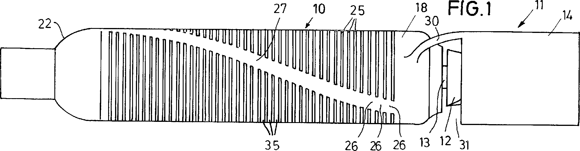
Die in den Figuren dargestellte Pumpe
weist einen Mikromotor
Der Mikromotor
An das rückwärtige Ende des Stators
Der Rückschlussmantel
Die Schlitze
Die Schlitze
Wie
Die Wandstärke des Rückschlussmantels beträgt etwa
0,25 mm, der Außendurchmesser
beträgt
4 mm und der Innendurchmesser 3,45 mm. Die Länge des Rückschlussmantels
Der Rückschlussmantel
Die zwischen den Stegen
Claims (6)
Priority Applications (8)
| Application Number | Priority Date | Filing Date | Title |
|---|---|---|---|
| DE10058669A DE10058669B4 (en) | 2000-11-25 | 2000-11-25 | micromotor |
| JP2002544110A JP4086185B2 (en) | 2000-11-25 | 2001-11-06 | Miniature motor |
| AU1236102A AU1236102A (en) | 2000-11-25 | 2001-11-06 | Miniature motor |
| AU2002212361A AU2002212361B2 (en) | 2000-11-25 | 2001-11-06 | Miniature motor |
| PCT/EP2001/012817 WO2002041935A1 (en) | 2000-11-25 | 2001-11-06 | Miniature motor |
| US10/432,470 US6794789B2 (en) | 2000-11-25 | 2001-11-06 | Miniature motor |
| EP01980544A EP1341568B1 (en) | 2000-11-25 | 2001-11-06 | Miniature motor |
| DE50111914T DE50111914D1 (en) | 2000-11-25 | 2001-11-06 | MINIATURE MOTOR |
Applications Claiming Priority (1)
| Application Number | Priority Date | Filing Date | Title |
|---|---|---|---|
| DE10058669A DE10058669B4 (en) | 2000-11-25 | 2000-11-25 | micromotor |
Publications (2)
| Publication Number | Publication Date |
|---|---|
| DE10058669A1 DE10058669A1 (en) | 2002-06-06 |
| DE10058669B4 true DE10058669B4 (en) | 2004-05-06 |
Family
ID=7664714
Family Applications (2)
| Application Number | Title | Priority Date | Filing Date |
|---|---|---|---|
| DE10058669A Expired - Fee Related DE10058669B4 (en) | 2000-11-25 | 2000-11-25 | micromotor |
| DE50111914T Expired - Lifetime DE50111914D1 (en) | 2000-11-25 | 2001-11-06 | MINIATURE MOTOR |
Family Applications After (1)
| Application Number | Title | Priority Date | Filing Date |
|---|---|---|---|
| DE50111914T Expired - Lifetime DE50111914D1 (en) | 2000-11-25 | 2001-11-06 | MINIATURE MOTOR |
Country Status (6)
| Country | Link |
|---|---|
| US (1) | US6794789B2 (en) |
| EP (1) | EP1341568B1 (en) |
| JP (1) | JP4086185B2 (en) |
| AU (2) | AU1236102A (en) |
| DE (2) | DE10058669B4 (en) |
| WO (1) | WO2002041935A1 (en) |
Families Citing this family (140)
| Publication number | Priority date | Publication date | Assignee | Title |
|---|---|---|---|---|
| US6889082B2 (en) | 1997-10-09 | 2005-05-03 | Orqis Medical Corporation | Implantable heart assist system and method of applying same |
| US7682301B2 (en) | 2003-09-18 | 2010-03-23 | Thoratec Corporation | Rotary blood pump |
| EP2151257B1 (en) | 2004-08-13 | 2013-04-17 | Delgado, Reynolds M., III | Apparatus for long-term assisting a left ventricle to pump blood |
| US7393181B2 (en) | 2004-09-17 | 2008-07-01 | The Penn State Research Foundation | Expandable impeller pump |
| US8419609B2 (en) | 2005-10-05 | 2013-04-16 | Heartware Inc. | Impeller for a rotary ventricular assist device |
| US7972122B2 (en) * | 2005-04-29 | 2011-07-05 | Heartware, Inc. | Multiple rotor, wide blade, axial flow pump |
| CA2611313A1 (en) | 2005-06-06 | 2006-12-14 | The Cleveland Clinic Foundation | Blood pump |
| WO2007112033A2 (en) | 2006-03-23 | 2007-10-04 | The Penn State Research Foundation | Heart assist device with expandable impeller pump |
| US20070231135A1 (en) | 2006-03-31 | 2007-10-04 | Orqis Medical Corporation | Rotary Blood Pump |
| US9028392B2 (en) | 2006-12-01 | 2015-05-12 | NuCardia, Inc. | Medical device |
| EP2131888B1 (en) | 2007-02-26 | 2017-04-05 | HeartWare, Inc. | Intravascular ventricular assist device |
| DE102007014224A1 (en) * | 2007-03-24 | 2008-09-25 | Abiomed Europe Gmbh | Blood pump with micromotor |
| US7828710B2 (en) * | 2007-06-05 | 2010-11-09 | Medical Value Partners, Llc | Apparatus comprising a drive cable for a medical device |
| US8079948B2 (en) * | 2007-08-29 | 2011-12-20 | NuCardia, Inc. | Article comprising an impeller |
| US8439859B2 (en) * | 2007-10-08 | 2013-05-14 | Ais Gmbh Aachen Innovative Solutions | Catheter device |
| JP5171953B2 (en) | 2008-06-23 | 2013-03-27 | テルモ株式会社 | Blood pump device |
| IT1394386B1 (en) * | 2008-09-29 | 2012-06-15 | Scuola Superiore Di Studi Universitari E Di Perfez | WOBBLE-TYPE ELECTROMAGNETIC STEP-BY-STEP MICROMOTOR |
| CA2739899C (en) | 2008-10-06 | 2017-05-16 | Indiana University Research And Technology Corporation | Apparatus for active or passive assistance in the circulatory system |
| US8550974B2 (en) | 2008-11-13 | 2013-10-08 | Robert Jarvik | Sub-miniature electromechanical medical implants with integrated hermetic feedthroughs |
| EP2194278A1 (en) | 2008-12-05 | 2010-06-09 | ECP Entwicklungsgesellschaft mbH | Fluid pump with a rotor |
| EP2372160B1 (en) | 2008-12-08 | 2014-07-30 | Thoratec Corporation | Centrifugal pump device |
| EP2216059A1 (en) | 2009-02-04 | 2010-08-11 | ECP Entwicklungsgesellschaft mbH | Catheter device with a catheter and an actuation device |
| JP5378010B2 (en) | 2009-03-05 | 2013-12-25 | ソラテック コーポレーション | Centrifugal pump device |
| CN102341600B (en) | 2009-03-06 | 2014-12-10 | 胸腔科技有限公司 | Centrifugal pump device |
| EP2229965A1 (en) | 2009-03-18 | 2010-09-22 | ECP Entwicklungsgesellschaft mbH | Fluid pump with particular form of a rotor blade |
| EP2246078A1 (en) | 2009-04-29 | 2010-11-03 | ECP Entwicklungsgesellschaft mbH | Shaft assembly with a shaft which moves within a fluid-filled casing |
| EP2248544A1 (en) | 2009-05-05 | 2010-11-10 | ECP Entwicklungsgesellschaft mbH | Fluid pump with variable circumference, particularly for medical use |
| EP2266640A1 (en) | 2009-06-25 | 2010-12-29 | ECP Entwicklungsgesellschaft mbH | Compressible and expandable turbine blade for a fluid pump |
| JP5815516B2 (en) | 2009-07-01 | 2015-11-17 | ザ・ペン・ステイト・リサーチ・ファウンデイションThe Penn State Research Foundation | Blood pump with expandable cannula |
| US8821365B2 (en) | 2009-07-29 | 2014-09-02 | Thoratec Corporation | Rotation drive device and centrifugal pump apparatus using the same |
| EP2282070B1 (en) | 2009-08-06 | 2012-10-17 | ECP Entwicklungsgesellschaft mbH | Catheter device with a coupling device for a drive device |
| EP2298371A1 (en) | 2009-09-22 | 2011-03-23 | ECP Entwicklungsgesellschaft mbH | Function element, in particular fluid pump with a housing and a transport element |
| EP3441616B1 (en) | 2009-09-22 | 2023-04-19 | ECP Entwicklungsgesellschaft mbH | Compressible rotor for a fluid pump |
| EP2298373A1 (en) | 2009-09-22 | 2011-03-23 | ECP Entwicklungsgesellschaft mbH | Fluid pump with at least one turbine blade and a seating device |
| EP2298372A1 (en) | 2009-09-22 | 2011-03-23 | ECP Entwicklungsgesellschaft mbH | Rotor for an axial pump for transporting a fluid |
| EP2314331B1 (en) | 2009-10-23 | 2013-12-11 | ECP Entwicklungsgesellschaft mbH | Catheter pump arrangement and flexible shaft arrangement with a cable core |
| EP2314330A1 (en) | 2009-10-23 | 2011-04-27 | ECP Entwicklungsgesellschaft mbH | Flexible shaft arrangement |
| US8690749B1 (en) | 2009-11-02 | 2014-04-08 | Anthony Nunez | Wireless compressible heart pump |
| EP2338541A1 (en) | 2009-12-23 | 2011-06-29 | ECP Entwicklungsgesellschaft mbH | Radial compressible and expandable rotor for a fluid pump |
| EP2338539A1 (en) | 2009-12-23 | 2011-06-29 | ECP Entwicklungsgesellschaft mbH | Pump device with a detection device |
| EP2338540A1 (en) | 2009-12-23 | 2011-06-29 | ECP Entwicklungsgesellschaft mbH | Delivery blade for a compressible rotor |
| EP2347778A1 (en) | 2010-01-25 | 2011-07-27 | ECP Entwicklungsgesellschaft mbH | Fluid pump with a radially compressible rotor |
| JP5443197B2 (en) | 2010-02-16 | 2014-03-19 | ソラテック コーポレーション | Centrifugal pump device |
| EP2363157A1 (en) | 2010-03-05 | 2011-09-07 | ECP Entwicklungsgesellschaft mbH | Device for exerting mechanical force on a medium, in particular fluid pump |
| EP2554191B1 (en) | 2010-03-26 | 2019-05-08 | Thoratec Corporation | Centrifugal blood pump device |
| EP2388029A1 (en) | 2010-05-17 | 2011-11-23 | ECP Entwicklungsgesellschaft mbH | Pump array |
| EP2399639A1 (en) | 2010-06-25 | 2011-12-28 | ECP Entwicklungsgesellschaft mbH | System for introducing a pump |
| JP5681403B2 (en) | 2010-07-12 | 2015-03-11 | ソーラテック コーポレイション | Centrifugal pump device |
| EP2407187A3 (en) | 2010-07-15 | 2012-06-20 | ECP Entwicklungsgesellschaft mbH | Blood pump for invasive application within the body of a patient |
| EP2407185A1 (en) | 2010-07-15 | 2012-01-18 | ECP Entwicklungsgesellschaft mbH | Radial compressible and expandable rotor for a pump with a turbine blade |
| EP2407186A1 (en) | 2010-07-15 | 2012-01-18 | ECP Entwicklungsgesellschaft mbH | Rotor for a pump, produced with an initial elastic material |
| EP2422735A1 (en) | 2010-08-27 | 2012-02-29 | ECP Entwicklungsgesellschaft mbH | Implantable blood transportation device, manipulation device and coupling device |
| JP5577506B2 (en) | 2010-09-14 | 2014-08-27 | ソーラテック コーポレイション | Centrifugal pump device |
| US8485961B2 (en) | 2011-01-05 | 2013-07-16 | Thoratec Corporation | Impeller housing for percutaneous heart pump |
| US8597170B2 (en) | 2011-01-05 | 2013-12-03 | Thoratec Corporation | Catheter pump |
| WO2012094641A2 (en) | 2011-01-06 | 2012-07-12 | Thoratec Corporation | Percutaneous heart pump |
| US8591393B2 (en) | 2011-01-06 | 2013-11-26 | Thoratec Corporation | Catheter pump |
| EP2497521A1 (en) | 2011-03-10 | 2012-09-12 | ECP Entwicklungsgesellschaft mbH | Push device for axial insertion of a string-shaped, flexible body |
| JP5969979B2 (en) | 2011-03-28 | 2016-08-17 | ソーラテック コーポレイション | Rotation drive device and centrifugal pump device using the same |
| EP2564771A1 (en) | 2011-09-05 | 2013-03-06 | ECP Entwicklungsgesellschaft mbH | Medicinal product with a functional element for invasive use in the body of a patient |
| US8926492B2 (en) | 2011-10-11 | 2015-01-06 | Ecp Entwicklungsgesellschaft Mbh | Housing for a functional element |
| JP6083929B2 (en) | 2012-01-18 | 2017-02-22 | ソーラテック コーポレイション | Centrifugal pump device |
| US11389638B2 (en) | 2012-02-07 | 2022-07-19 | Hridaya, Inc. | Hemodynamic assist device |
| AU2013217061B2 (en) | 2012-02-07 | 2017-09-28 | Hridaya, Inc. | Hemodynamic assist device |
| EP2830675B1 (en) | 2012-03-26 | 2025-06-25 | Procyrion, Inc. | Systems and methods for fluid flows and/or pressures for circulation and perfusion enhancement |
| US9446179B2 (en) | 2012-05-14 | 2016-09-20 | Thoratec Corporation | Distal bearing support |
| US9327067B2 (en) | 2012-05-14 | 2016-05-03 | Thoratec Corporation | Impeller for catheter pump |
| US9872947B2 (en) | 2012-05-14 | 2018-01-23 | Tc1 Llc | Sheath system for catheter pump |
| GB2504176A (en) | 2012-05-14 | 2014-01-22 | Thoratec Corp | Collapsible impeller for catheter pump |
| DE102013008159A1 (en) | 2012-05-14 | 2013-11-14 | Thoratec Corporation | Sheath system for catheter pump |
| US8721517B2 (en) | 2012-05-14 | 2014-05-13 | Thoratec Corporation | Impeller for catheter pump |
| EP4186557A1 (en) | 2012-07-03 | 2023-05-31 | Tc1 Llc | Motor assembly for catheter pump |
| US9358329B2 (en) | 2012-07-03 | 2016-06-07 | Thoratec Corporation | Catheter pump |
| US9421311B2 (en) | 2012-07-03 | 2016-08-23 | Thoratec Corporation | Motor assembly for catheter pump |
| US9371826B2 (en) | 2013-01-24 | 2016-06-21 | Thoratec Corporation | Impeller position compensation using field oriented control |
| US9556873B2 (en) | 2013-02-27 | 2017-01-31 | Tc1 Llc | Startup sequence for centrifugal pump with levitated impeller |
| US11033728B2 (en) | 2013-03-13 | 2021-06-15 | Tc1 Llc | Fluid handling system |
| US11077294B2 (en) | 2013-03-13 | 2021-08-03 | Tc1 Llc | Sheath assembly for catheter pump |
| EP4122520A1 (en) | 2013-03-13 | 2023-01-25 | Tc1 Llc | Fluid handling system |
| US9308302B2 (en) | 2013-03-15 | 2016-04-12 | Thoratec Corporation | Catheter pump assembly including a stator |
| US20160030649A1 (en) | 2013-03-15 | 2016-02-04 | Thoratec Corporation | Catheter pump assembly including a stator |
| US10052420B2 (en) | 2013-04-30 | 2018-08-21 | Tc1 Llc | Heart beat identification and pump speed synchronization |
| US9713663B2 (en) | 2013-04-30 | 2017-07-25 | Tc1 Llc | Cardiac pump with speed adapted for ventricle unloading |
| US9827356B2 (en) | 2014-04-15 | 2017-11-28 | Tc1 Llc | Catheter pump with access ports |
| WO2015160943A1 (en) | 2014-04-15 | 2015-10-22 | Thoratec Corporation | Sensors for catheter pumps |
| EP4417244A3 (en) | 2014-04-15 | 2024-10-16 | Tc1 Llc | Catheter pump introducer system |
| US10583232B2 (en) | 2014-04-15 | 2020-03-10 | Tc1 Llc | Catheter pump with off-set motor position |
| WO2016028644A1 (en) | 2014-08-18 | 2016-02-25 | Thoratec Corporation | Guide features for percutaneous catheter pump |
| US9623161B2 (en) | 2014-08-26 | 2017-04-18 | Tc1 Llc | Blood pump and method of suction detection |
| US9675738B2 (en) | 2015-01-22 | 2017-06-13 | Tc1 Llc | Attachment mechanisms for motor of catheter pump |
| EP3247420B1 (en) | 2015-01-22 | 2019-10-02 | Tc1 Llc | Reduced rotational mass motor assembly for catheter pump |
| EP3247421B1 (en) | 2015-01-22 | 2019-10-02 | Tc1 Llc | Motor assembly with heat exchanger for catheter pump |
| EP3256183B1 (en) | 2015-02-11 | 2025-08-13 | Tc1 Llc | Heart beat identification and pump speed synchronization |
| US10371152B2 (en) | 2015-02-12 | 2019-08-06 | Tc1 Llc | Alternating pump gaps |
| WO2016130944A1 (en) | 2015-02-12 | 2016-08-18 | Thoratec Corporation | System and method for controlling the position of a levitated rotor |
| US10245361B2 (en) | 2015-02-13 | 2019-04-02 | Tc1 Llc | Impeller suspension mechanism for heart pump |
| US9907890B2 (en) | 2015-04-16 | 2018-03-06 | Tc1 Llc | Catheter pump with positioning brace |
| EP3352808B1 (en) * | 2015-09-25 | 2023-09-20 | Procyrion, Inc. | Non-occluding intravascular blood pump providing reduced hemolysis |
| EP3153191A1 (en) * | 2015-10-09 | 2017-04-12 | ECP Entwicklungsgesellschaft mbH | Blood pump |
| US10117983B2 (en) | 2015-11-16 | 2018-11-06 | Tc1 Llc | Pressure/flow characteristic modification of a centrifugal pump in a ventricular assist device |
| WO2018017683A1 (en) | 2016-07-21 | 2018-01-25 | Thoratec Corporation | Gas-filled chamber for catheter pump motor assembly |
| US11160970B2 (en) | 2016-07-21 | 2021-11-02 | Tc1 Llc | Fluid seals for catheter pump motor assembly |
| CN110944689B (en) | 2017-06-07 | 2022-12-09 | 施菲姆德控股有限责任公司 | Intravascular fluid movement devices, systems, and methods of use |
| DE102017217619A1 (en) | 2017-10-04 | 2019-04-04 | Bühler Motor GmbH | Electronically commutated DC motor |
| US11511103B2 (en) | 2017-11-13 | 2022-11-29 | Shifamed Holdings, Llc | Intravascular fluid movement devices, systems, and methods of use |
| DE102018201030B4 (en) | 2018-01-24 | 2025-10-16 | Kardion Gmbh | Magnetic dome element with magnetic bearing function |
| EP4085965A1 (en) | 2018-02-01 | 2022-11-09 | Shifamed Holdings, LLC | Intravascular blood pumps and methods of use and manufacture |
| JP2019176713A (en) * | 2018-03-28 | 2019-10-10 | パナソニックIpマネジメント株式会社 | Motor shaft, rotor, motor, and blower |
| DE102018207611A1 (en) | 2018-05-16 | 2019-11-21 | Kardion Gmbh | Rotor bearing system |
| DE102018207575A1 (en) | 2018-05-16 | 2019-11-21 | Kardion Gmbh | Magnetic face turning coupling for the transmission of torques |
| DE102018207622A1 (en) * | 2018-05-16 | 2019-11-21 | Kardion Gmbh | Permanent magnetic radial rotary coupling and micropump with such a radial rotary coupling |
| DE102018208539A1 (en) | 2018-05-30 | 2019-12-05 | Kardion Gmbh | A motor housing module for sealing an engine compartment of a motor of a cardiac assist system and cardiac assistance system and method for mounting a cardiac assist system |
| DE102018208541A1 (en) | 2018-05-30 | 2019-12-05 | Kardion Gmbh | Axial pump for a cardiac assist system and method of making an axial pump for a cardiac assist system |
| DE102018208550A1 (en) | 2018-05-30 | 2019-12-05 | Kardion Gmbh | A lead device for directing blood flow to a cardiac assist system, cardiac assist system, and method of making a lead device |
| DE102018208538A1 (en) | 2018-05-30 | 2019-12-05 | Kardion Gmbh | Intravascular blood pump and process for the production of electrical conductors |
| DE102018208555A1 (en) | 2018-05-30 | 2019-12-05 | Kardion Gmbh | Apparatus for anchoring a cardiac assist system in a blood vessel, method of operation, and method of making a device and cardiac assist system |
| DE102018208549A1 (en) | 2018-05-30 | 2019-12-05 | Kardion Gmbh | Electronic module for a cardiac assist system and method for manufacturing an electronic module for a cardiac assist system |
| DE102018210058A1 (en) | 2018-06-21 | 2019-12-24 | Kardion Gmbh | Stator blade device for guiding the flow of a fluid flowing out of an outlet opening of a heart support system, heart support system with stator blade device, method for operating a stator blade device and manufacturing method |
| DE102018210076A1 (en) | 2018-06-21 | 2019-12-24 | Kardion Gmbh | Method and device for detecting a state of wear of a cardiac support system, method and device for operating a cardiac support system and cardiac support system |
| DE102018211297A1 (en) | 2018-07-09 | 2020-01-09 | Kardion Gmbh | Cardiac support system and method for monitoring the integrity of a support structure of a cardiac support system |
| DE102018211327A1 (en) | 2018-07-10 | 2020-01-16 | Kardion Gmbh | Impeller for an implantable vascular support system |
| DE102018211328A1 (en) | 2018-07-10 | 2020-01-16 | Kardion Gmbh | Impeller housing for an implantable vascular support system |
| DE102018212153A1 (en) | 2018-07-20 | 2020-01-23 | Kardion Gmbh | Inlet line for a pump unit of a cardiac support system, cardiac support system and method for producing an inlet line for a pump unit of a cardiac support system |
| WO2020028537A1 (en) | 2018-07-31 | 2020-02-06 | Shifamed Holdings, Llc | Intravascaular blood pumps and methods of use |
| WO2020030700A1 (en) | 2018-08-07 | 2020-02-13 | Kardion Gmbh | Bearing device for a heart support system, and method for rinsing a space in a bearing device for a heart support system |
| JP7470108B2 (en) | 2018-10-05 | 2024-04-17 | シファメド・ホールディングス・エルエルシー | Intravascular blood pump and method of use |
| EP3711785A1 (en) * | 2019-03-19 | 2020-09-23 | Abiomed Europe GmbH | Blood pump |
| WO2021011473A1 (en) | 2019-07-12 | 2021-01-21 | Shifamed Holdings, Llc | Intravascular blood pumps and methods of manufacture and use |
| WO2021016372A1 (en) | 2019-07-22 | 2021-01-28 | Shifamed Holdings, Llc | Intravascular blood pumps with struts and methods of use and manufacture |
| US12465748B2 (en) | 2019-08-07 | 2025-11-11 | Supira Medical, Inc. | Catheter blood pumps and collapsible pump housings |
| WO2021062260A1 (en) | 2019-09-25 | 2021-04-01 | Shifamed Holdings, Llc | Catheter blood pumps and collapsible blood conduits |
| US12102815B2 (en) | 2019-09-25 | 2024-10-01 | Shifamed Holdings, Llc | Catheter blood pumps and collapsible pump housings |
| EP4034192B1 (en) | 2019-09-25 | 2025-12-24 | Supira Medical, Inc. | Intravascular blood pump systems and methods of use and control thereof |
| EP4069347A4 (en) | 2019-12-03 | 2023-12-27 | Procyrion, Inc. | Blood pumps |
| US12409310B2 (en) | 2019-12-11 | 2025-09-09 | Shifamed Holdings, Llc | Descending aorta and vena cava blood pumps |
| CN115279451A (en) | 2019-12-13 | 2022-11-01 | 普罗西里翁公司 | Support structure for intravascular blood pump |
| EP4477253A3 (en) | 2020-01-10 | 2025-02-19 | Abiomed, Inc. | Blood pump with improved leakage control and method for producing the same |
| DE102020102474A1 (en) | 2020-01-31 | 2021-08-05 | Kardion Gmbh | Pump for conveying a fluid and method for manufacturing a pump |
| EP4210809A1 (en) | 2020-09-14 | 2023-07-19 | Kardion GmbH | Cardiovascular support pump having an impeller with a variable flow area |
| US20220161021A1 (en) * | 2020-11-20 | 2022-05-26 | Kardion Gmbh | Mechanical circulatory support system with insertion tool |
Citations (2)
| Publication number | Priority date | Publication date | Assignee | Title |
|---|---|---|---|---|
| WO1998044619A1 (en) * | 1997-04-02 | 1998-10-08 | Impella Cardiotechnik Gmbh | Method for producing a micromotor |
| DE19821307C1 (en) * | 1998-05-13 | 1999-10-21 | Impella Cardiotech Gmbh | Intra-cardiac blood pump |
Family Cites Families (11)
| Publication number | Priority date | Publication date | Assignee | Title |
|---|---|---|---|---|
| US3680671A (en) * | 1970-07-28 | 1972-08-01 | Vibrac Corp | Magnetic devices |
| JPS5755762A (en) * | 1980-09-19 | 1982-04-02 | Japan Servo Co Ltd | Permanent magnet type stepping motor |
| FR2514582A1 (en) * | 1981-10-08 | 1983-04-15 | Artus | BRUSHLESS ELECTRIC MICROMOTOR |
| US4679313A (en) * | 1985-03-08 | 1987-07-14 | Kollmorgen Technologies Corporation | Method of making a servo motor with high energy product magnets |
| US4968911A (en) * | 1985-11-20 | 1990-11-06 | Allied-Signal Inc. | Clam-shell stator construction for electrical machines |
| US5142178A (en) * | 1991-04-12 | 1992-08-25 | Emerson Electric Co. | Apparatus for aligning stacked laminations of a dynamoelectric machine |
| US5527159A (en) * | 1993-11-10 | 1996-06-18 | The United States Of America As Represented By The Administrator Of The National Aeronautics And Space Administration | Rotary blood pump |
| US5689147A (en) * | 1994-02-07 | 1997-11-18 | Nidec Corporation | Brushless motor |
| FR2721452B1 (en) * | 1994-06-17 | 1996-09-06 | Leroy Somer Moteurs | Coiled stator with notches for a rotating electric machine, method for producing such a stator and machine comprising such a stator. |
| EP0764448B1 (en) * | 1995-09-22 | 2003-07-30 | United States Surgical Corporation | Cardiac support device |
| US5911685A (en) * | 1996-04-03 | 1999-06-15 | Guidant Corporation | Method and apparatus for cardiac blood flow assistance |
-
2000
- 2000-11-25 DE DE10058669A patent/DE10058669B4/en not_active Expired - Fee Related
-
2001
- 2001-11-06 JP JP2002544110A patent/JP4086185B2/en not_active Expired - Lifetime
- 2001-11-06 US US10/432,470 patent/US6794789B2/en not_active Expired - Lifetime
- 2001-11-06 DE DE50111914T patent/DE50111914D1/en not_active Expired - Lifetime
- 2001-11-06 WO PCT/EP2001/012817 patent/WO2002041935A1/en not_active Ceased
- 2001-11-06 AU AU1236102A patent/AU1236102A/en active Pending
- 2001-11-06 AU AU2002212361A patent/AU2002212361B2/en not_active Expired
- 2001-11-06 EP EP01980544A patent/EP1341568B1/en not_active Expired - Lifetime
Patent Citations (2)
| Publication number | Priority date | Publication date | Assignee | Title |
|---|---|---|---|---|
| WO1998044619A1 (en) * | 1997-04-02 | 1998-10-08 | Impella Cardiotechnik Gmbh | Method for producing a micromotor |
| DE19821307C1 (en) * | 1998-05-13 | 1999-10-21 | Impella Cardiotech Gmbh | Intra-cardiac blood pump |
Also Published As
| Publication number | Publication date |
|---|---|
| AU1236102A (en) | 2002-06-03 |
| DE50111914D1 (en) | 2007-03-08 |
| JP2004514090A (en) | 2004-05-13 |
| US6794789B2 (en) | 2004-09-21 |
| JP4086185B2 (en) | 2008-05-14 |
| WO2002041935A1 (en) | 2002-05-30 |
| EP1341568B1 (en) | 2007-01-17 |
| EP1341568A1 (en) | 2003-09-10 |
| DE10058669A1 (en) | 2002-06-06 |
| AU2002212361B2 (en) | 2005-08-11 |
| US20040046466A1 (en) | 2004-03-11 |
Similar Documents
| Publication | Publication Date | Title |
|---|---|---|
| DE10058669B4 (en) | micromotor | |
| EP2129410B1 (en) | Blood pump comprising a micromotor | |
| EP3359215B1 (en) | Pump, in particular blood pump | |
| DE112021000800T5 (en) | INTRAVASCULAR BLOOD PUMP | |
| EP2520317B1 (en) | Blood pump | |
| EP1233797B1 (en) | Intravascular blood pump | |
| DE19613564C1 (en) | Intravascular blood pump | |
| DE2613061C3 (en) | Drive motor for a dental handpiece and contra-angle | |
| DE19808550C1 (en) | Electric motor, esp. a permanent magnet stimulated electric motor | |
| EP1850450A2 (en) | Electric motor | |
| DE69806179T2 (en) | WIRE GUIDE ARRANGEMENT FOR THE ELECTRIC MACHINE ROTOR | |
| DE102022202728A1 (en) | fluid machine and underwater vehicle | |
| DE7908892U1 (en) | Brush holder slip ring assembly | |
| DE102007019067A1 (en) | Stator component for e.g. electric motor, has coils provided for surrounding stator tooth of end units, where end units are joined with one another along partition line that runs perpendicular to longitudinal axis of electric motor | |
| EP0872005B1 (en) | Plate for electrodynamic machines | |
| DE10062537A1 (en) | Component joining method for X-ray tubes, involves using coupling to join two X-ray tube components to nullify dissimilar thermal expansion rates and maintain interference fit throughout coupling operating temperature | |
| DE1913714A1 (en) | Electric speed sensor | |
| DE1942986A1 (en) | Dynamo-electric machine | |
| DE7540211U (en) | Ring with two collector tracks for an electrical machine | |
| DE112020001847T5 (en) | Integrated motor and integrated pump with axially arranged coils | |
| DE2435034A1 (en) | ENGINE | |
| DE1613368A1 (en) | Stator of a permanently magnetically excited miniature motor | |
| DE3038885A1 (en) | Electro-stimulation probe for e.g. pacemaker - has conductors as ducts contg. conductive liq. | |
| DE3230699C2 (en) | ||
| WO2009049807A1 (en) | Electric motor for use in a dentist's, dental surgeon's or dental technician's hand piece |
Legal Events
| Date | Code | Title | Description |
|---|---|---|---|
| OP8 | Request for examination as to paragraph 44 patent law | ||
| 8364 | No opposition during term of opposition | ||
| 8327 | Change in the person/name/address of the patent owner |
Owner name: IMPELLA CARDIOSYSTEMS AG, 52074 AACHEN, DE |
|
| 8339 | Ceased/non-payment of the annual fee |