CN2734251Y - Impulse generating device of implantation type brain artificial pacemaker for treating Parkinson's disease - Google Patents
Impulse generating device of implantation type brain artificial pacemaker for treating Parkinson's disease Download PDFInfo
- Publication number
- CN2734251Y CN2734251Y CN 200420009300 CN200420009300U CN2734251Y CN 2734251 Y CN2734251 Y CN 2734251Y CN 200420009300 CN200420009300 CN 200420009300 CN 200420009300 U CN200420009300 U CN 200420009300U CN 2734251 Y CN2734251 Y CN 2734251Y
- Authority
- CN
- China
- Prior art keywords
- chip microcomputer
- pulse generator
- links
- pulse
- chip
- Prior art date
- Legal status (The legal status is an assumption and is not a legal conclusion. Google has not performed a legal analysis and makes no representation as to the accuracy of the status listed.)
- Expired - Fee Related
Links
Images

Landscapes
- Electrotherapy Devices (AREA)
Abstract
一种治疗帕金森病的植入式脑起搏器脉冲发生器,发出的电脉冲通过导线传到植入脑内的刺激电极,用持续的脉冲电刺激治疗帕金森病。脉冲发生器由高集成度低功耗单片机、电池、稳压器、射频通讯、簧片开关、脉冲发生和驱动器等组成,尽可能简化电路设计,用软件实现脑起搏器的各种功能,提高了系统可靠性。脉冲发生器由外部磁铁和编程器非接触式控制启动/停止和调节脉冲参数。脉冲发生器对靶点区域实现刺激强度、频率、脉宽等参数可调的电刺激,有利于找到最佳刺激触点,从而具有疗效更好,更持久等优点。
An implantable brain pacemaker pulse generator for the treatment of Parkinson's disease. The electrical pulse sent is transmitted to the stimulation electrode implanted in the brain through a wire, and the Parkinson's disease is treated with continuous pulse electrical stimulation. The pulse generator is composed of highly integrated low-power single-chip microcomputer, battery, voltage regulator, radio frequency communication, reed switch, pulse generator and driver, etc. It simplifies the circuit design as much as possible, and uses software to realize various functions of the brain pacemaker. Improved system reliability. The pulse generator is controlled by an external magnet and a programmer for non-contact start/stop and adjustment of pulse parameters. The pulse generator achieves electrical stimulation with adjustable parameters such as stimulation intensity, frequency, and pulse width to the target area, which is conducive to finding the best stimulation contact point, so that it has the advantages of better curative effect and longer duration.
Description
技术领域technical field
本实用新型涉及一种通过对大脑靶点组织的慢性电刺激作用治疗帕金森病的可植入脑起搏器脉冲发生器,为一种深部脑刺激治疗仪。The utility model relates to an implantable brain pacemaker pulse generator for treating Parkinson's disease through chronic electrical stimulation of brain target tissue, which is a deep brain stimulation treatment instrument.
背景技术Background technique
帕金森病是发生在中年以上的中枢神经系统变性疾病,主要病变在大脑的黑质和纹状体。药物治疗是帕金森病最基本的治疗手段,传统的外科治疗主要采用病变区毁损方法。脑起搏器治疗通过慢性电刺激来达到治疗效果,效果完全与毁损术相媲美,而且是一种可逆性的神经调节治疗,不破坏脑组织,起到对因治疗作用,延缓帕金森病本身病情进展,是目前最理想的外科治疗方法。植入式脑起搏器由脑内电极、延长导线和脉冲发生器组成。通过手术将脉冲发生器埋置在胸部锁骨附近皮下,刺激电极通过立体定向技术、微电极记录技术插入脑内特定核团。脉冲发生器发出的电脉冲通过一条植于皮下,通过头、颈、肩的导线传到刺激电极,作用于脑内特定核团,用持续的脉冲电刺激抑制不正常的脑核团放电,达到治疗帕金森病的效果。Parkinson's disease is a degenerative disease of the central nervous system that occurs in middle age and above, and the main lesions are in the substantia nigra and striatum of the brain. Drug therapy is the most basic treatment method for Parkinson's disease, and traditional surgical treatment mainly uses the method of destroying the lesion. Brain pacemaker therapy achieves the therapeutic effect through chronic electrical stimulation, the effect is completely comparable to that of lesion surgery, and it is a reversible neuromodulation therapy that does not destroy brain tissue, plays a role in treating the cause, and delays Parkinson's disease itself Progression of the disease is currently the most ideal surgical treatment. An implanted brain pacemaker consists of electrodes in the brain, extension leads, and a pulse generator. The pulse generator is implanted subcutaneously near the clavicle in the chest through surgery, and the stimulating electrodes are inserted into specific nuclei in the brain through stereotaxic technology and microelectrode recording technology. The electrical pulse sent by the pulse generator is transmitted to the stimulating electrode through a wire implanted under the skin, through the head, neck, and shoulders, and acts on specific nuclei in the brain, and uses continuous pulse electrical stimulation to suppress the discharge of abnormal brain nuclei to achieve The effect of treating Parkinson's disease.
中国发明专利“多通道可植入的神经刺激器”(申请号86103049),用外部传送器把数字编码信号连同能量通过皮肤送入植入的接收器/刺激器,刺激器将位流解码,把电荷或电流波形送入植入听觉神经或耳蜗的电极。该刺激器必须由外部传送器控制同时工作,电路结构和算法决定了该刺激器只能用于听觉神经修补系统,不适用帕金森病的脑起搏器治疗。已公开的中国发明专利(申请号01810456.8)“用于刺激有机体器官和组织的植入式和可编程电刺激器”,将生物传感器遍布外壳的整个表面,疾病导致的呼吸和心血管的变化被传感器记录,根据一定的算法,在线电极上形成电流脉冲。该刺激器以呼吸和心血管的生理信号为依据,通过电刺激改变组织器官的机能活动,其系统方案、电路结构和算法不能用于帕金森病的脑起搏器治疗。Chinese invention patent "multi-channel implantable neurostimulator" (application number 86103049), uses an external transmitter to send digitally encoded signals and energy through the skin to the implanted receiver/stimulator, and the stimulator decodes the bit stream, A charge or current waveform is sent to electrodes implanted in the auditory nerve or cochlea. The stimulator must be controlled by an external transmitter to work at the same time. The circuit structure and algorithm determine that the stimulator can only be used in the auditory nerve repair system, and it is not suitable for the brain pacemaker treatment of Parkinson's disease. The published Chinese invention patent (Application No. 01810456.8) "Implantable and Programmable Electrical Stimulator for Stimulating Organs and Tissues of Organisms" spreads biosensors all over the surface of the shell, and the respiratory and cardiovascular changes caused by diseases are detected The sensor records, according to a certain algorithm, the formation of current pulses on the wire electrodes. Based on the physiological signals of breathing and cardiovascular, the stimulator changes the functional activities of tissues and organs through electrical stimulation, and its system scheme, circuit structure and algorithm cannot be used for the brain pacemaker treatment of Parkinson's disease.
发明内容Contents of the invention
本实用新型的目的是提供一种治疗帕金森病的植入式脑起搏器用的脉冲发生器,根据外部编程器设置的脉冲参数,向靶点区域提供电脉冲刺激。The purpose of the utility model is to provide a pulse generator for an implantable brain pacemaker for treating Parkinson's disease, which can provide electric pulse stimulation to the target area according to the pulse parameters set by an external programmer.
本实用新型的特征在于,它含有:The utility model is characterized in that it contains:
1.单片机,采用芯片MSP430F155;1. Single-chip microcomputer, using chip MSP430F155;
2.电源变换器,采用芯片AS1117,其输入端接电池,输出端接上述单片机的电源端;2. The power converter adopts the chip AS1117, its input terminal is connected to the battery, and its output terminal is connected to the power terminal of the above-mentioned single-chip microcomputer;
3.脉冲发生与驱动电路,含有:3. Pulse generation and drive circuit, including:
电压源,采用微功耗开关型电压变换芯片MAX630,其电源低电位检测端LB1经分压电阻接电源,而输出端Vs接刺激电极正端,反馈端Vfb则经一组并联的取样电阻后与上述单片机的相应IO端口相连,同时经过一个固定电阻与Vs相连。The voltage source adopts the micro-power switch-type voltage conversion chip MAX630. The low-potential detection terminal LB1 of the power supply is connected to the power supply through a voltage dividing resistor, while the output terminal Vs is connected to the positive terminal of the stimulating electrode, and the feedback terminal Vfb is connected to a set of parallel sampling resistors. It is connected to the corresponding IO port of the above-mentioned single-chip microcomputer, and is connected to Vs through a fixed resistor at the same time.
电流源,含有:current source, containing:
运算放大器,其正输入端经电阻与上述单片机的一个输出端相连,而负输入端经一组并联的电阻后分别与上述单片机的相应IO端口相连。The positive input terminal of the operational amplifier is connected to an output terminal of the above-mentioned single-chip microcomputer through a resistor, and the negative input terminal is respectively connected to the corresponding IO ports of the above-mentioned single-chip microcomputer through a group of parallel resistors.
第一个NPN三极管,其基极与上述运算放大器的输出端相连,其射极经互相串联的一个电阻和一个下述簧片开关(即磁控双掷开关)的常闭端后接地;其集电极经电阻与一个PNP三极管基极相连,该PNP三极管集电极与上述单片机一个IO端口相连。The first NPN triode, its base is connected with the output terminal of the above-mentioned operational amplifier, and its emitter is grounded after a resistor connected in series and a normally closed end of a following reed switch (i.e. magnetically controlled double-throw switch); The collector is connected to the base of a PNP transistor through a resistor, and the collector of the PNP transistor is connected to an IO port of the above-mentioned single-chip microcomputer.
第二个NPN三极管,其基极在经一个正向二极管与上述第一个NPN三极管集电极相连的同时,又经一个电容与上述MAX630芯片的输出端Vs相连;其集电极经正极接地的稳压管后接刺激电极的正端;其射极经正极接地的稳压管后再经一个电容与刺激电极的负端相连。The base of the second NPN transistor is connected to the collector of the first NPN transistor through a forward diode, and at the same time connected to the output terminal Vs of the above-mentioned MAX630 chip through a capacitor; The positive terminal of the stimulating electrode is connected to the back of the voltage tube; the emitter is connected to the negative terminal of the stimulating electrode through a capacitor through a voltage regulator tube whose positive electrode is grounded.
4.信号接收/复位电路,含有:4. Signal receiving/resetting circuit, including:
第三个NPN三极管,其集电极经上拉电阻作用后与上述单片机的一个串行输入口相连;其基极在对地反接的稳压管与电阻分压支路的终点相连后,又经一个电容、一个感应控制信号用的线圈电感后接地。The third NPN triode, its collector is connected to a serial input port of the above-mentioned single-chip microcomputer after being acted on by a pull-up resistor; its base is connected to the end point of the resistance voltage dividing branch after the voltage regulator tube connected to the ground is reversed, and then After passing through a capacitor and a coil inductance for sensing control signals, it is grounded.
簧片开关即磁控双掷开关,其常闭端经固定端接地,常开端经上拉电阻作用后再经限流电阻接上述单片机的RST端,即复位端。The reed switch is a magnetically controlled double-throw switch. Its normally closed end is grounded through the fixed end, and the normally open end is connected to the RST end of the above-mentioned single-chip microcomputer through the current limiting resistor after the action of the pull-up resistor, that is, the reset end.
所述单片机有一个与外部编程器无线连接的射频通讯电路用的通讯接口。The single-chip microcomputer has a communication interface for a radio frequency communication circuit wirelessly connected with an external programmer.
所述的MAX630芯片,其Cx端、Lx端对地分别连接着一个用于调整内部开关频率的电容和电感。In the MAX630 chip, its Cx terminal and Lx terminal are respectively connected to a capacitor and an inductance for adjusting the internal switching frequency.
所述单片机外接了调整工作频率用的32.768KHz和8MHz的两个晶振。The single-chip microcomputer is externally connected with two crystal oscillators of 32.768KHz and 8MHz for adjusting the working frequency.
本实用新型工作过程如下:The utility model work process is as follows:
只需用磁铁在胸前位置一碰,脉冲发生器启动,单片机读取数据FLASH中的脉冲参数(包括频率、脉宽、幅度等),控制脉冲发生和驱动电路输出电脉冲,经过延伸导线施加在电极上,从而在靶点区域放电,缓解病人的症状。磁铁再一碰,脉冲发生器停止输出脉冲。本实用新型使用简单,对靶点区域实现刺激强度、频率、脉宽等参数可调的电刺激,从而能够找到最佳刺激触点,具有疗效更好,更持久等优点。Just touch the chest position with a magnet, the pulse generator starts, the single-chip microcomputer reads the pulse parameters (including frequency, pulse width, amplitude, etc.) On the electrodes, thereby discharging in the targeted area, relieving the patient's symptoms. Once the magnet touches again, the pulse generator stops outputting pulses. The utility model is easy to use, and realizes electric stimulation with adjustable parameters such as stimulation intensity, frequency, and pulse width on the target area, so that the best stimulation contact point can be found, and the utility model has the advantages of better curative effect and longer duration.
附图说明Description of drawings
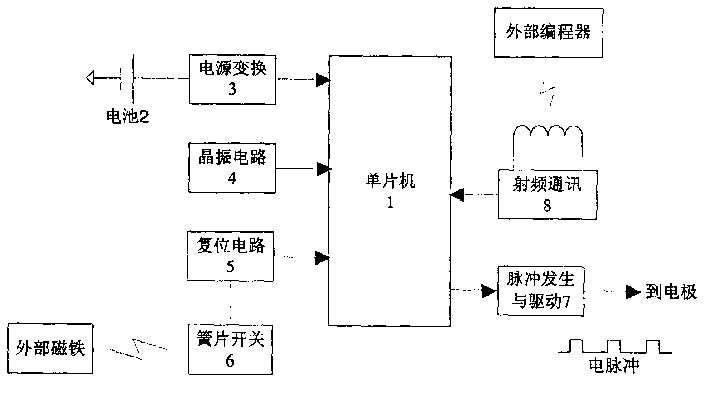
图1是本实用新型的原理结构框图。Fig. 1 is a block diagram of the principle structure of the utility model.
图2是本实用新型的电路原理图。Fig. 2 is the schematic circuit diagram of the utility model.
具体实施方式Detailed ways
本实用新型的技术解决方案如下:The technical solution of the utility model is as follows:
本实用新型提供的脉冲发生器,由单片机、电池、电源变换、射频通讯、簧片开关、脉冲发生与驱动等电路组成。脉冲发生器选用高集成度低功耗单片机,具有5种节电模式,集成程序FLASH、数据RAM、数据FLASH、定时器、模拟-数字转换器AD、数字-模拟转换器DA、比较器、串行通讯端口等,尽可能用软件来实现起搏器的各种功能,以简化电路设计、提高系统可靠性。簧片开关和射频通讯电路是脉冲发生器接受外部控制的接口,患者或者医生可用外部磁铁启动或停止脉冲发生器,并可用编程器调整刺激脉冲的参数。单片机的脉冲发生与驱动电路是通过电压源和电流源的协同作用输出电脉冲,通过电极放电作用于靶点的脑组织。The pulse generator provided by the utility model is composed of single-chip microcomputer, battery, power conversion, radio frequency communication, reed switch, pulse generation and driving circuits. The pulse generator uses a highly integrated low-power single-chip microcomputer, with 5 power-saving modes, integrated program FLASH, data RAM, data FLASH, timer, analog-to-digital converter AD, digital-to-analog converter DA, comparator, serial Communication ports, etc., use software to implement various functions of the pacemaker as much as possible, so as to simplify circuit design and improve system reliability. The reed switch and the radio frequency communication circuit are the interfaces for the pulse generator to accept external control. The patient or doctor can start or stop the pulse generator with an external magnet, and can adjust the parameters of the stimulation pulse with the programmer. The pulse generation and driving circuit of the single-chip microcomputer outputs electric pulses through the synergistic effect of the voltage source and the current source, and acts on the target brain tissue through electrode discharge.
下面结合附图描述本实用新型的一个实施例。Describe an embodiment of the present utility model below in conjunction with accompanying drawing.
附图1是本实用新型的电路结构图。以高集成度低功耗单片机1为核心,由锂电池2供电,通过电源变换3得到系统需要的电压,晶振电路4提供时钟,即构成单片机系统。簧片开关6为磁控开关,与复位电路5配合,可由外部磁铁控制脉冲发生器在工作状态和停止状态切换。单片机1通过射频通讯电路8接收外部编程器发送的脉冲参数数据。根据设定的参数,单片机控制脉冲发生和驱动电路7向电极输出电脉冲,对脑组织的靶点区域进行电刺激。(外部磁铁和编程器的设计不属于本实用新型的涉及范围)Accompanying drawing 1 is the circuit structure diagram of the present utility model. With high integration and low power consumption single-chip microcomputer 1 as the core, powered by
附图2是本实用新型的电路原理图。脉冲发生器包括电源变换单元,控制单元,电压源,电流源和信号接收/复位电路。电压源和电流源在单片机的控制下协同工作,实现电脉冲的发生和驱动功能。Accompanying
电源变换单元由高性能锂电池、稳压芯片AS1117组成,电池的输出电压经AS1117稳压后向各个芯片供电。The power conversion unit is composed of a high-performance lithium battery and a voltage regulator chip AS1117, and the output voltage of the battery is regulated by the AS1117 to supply power to each chip.
控制单元以单片机MSP430F155为核心,通过IO端口控制电压源和电流源的输出,调整施加在电极上的刺激脉冲的参数。单片机外接32.768kHz和8MHz两个晶振,以实现在不同的工作状态时调整工作频率,节省功耗。The control unit takes MSP430F155 as the core, controls the output of the voltage source and current source through the IO port, and adjusts the parameters of the stimulation pulse applied to the electrodes. The MCU is externally connected with two crystal oscillators of 32.768kHz and 8MHz to adjust the working frequency in different working states and save power consumption.
电压源由微功耗开关型电压变换芯片MAX630,以及电感、电阻和电容等分立元件组成。MAX630由电池直接供电,其内部开关频率由电感L3和电容C22决定,MAX630的输出端经分压电阻网络后接回反馈端。取样电阻R33、R34、R35、R36与单片机的IO端口相连,通过改变接地的取样电阻的数目,可以调整MAX630的输出电压,以及植入电极间放电的极限电压幅值。脉冲发生器工作时,单片机在程序控制下周期性改变MAX630的输出电压,即可刺激电脉冲的脉宽和频率调节。The voltage source consists of a micro-power switch type voltage conversion chip MAX630, and discrete components such as inductors, resistors, and capacitors. The MAX630 is directly powered by the battery, and its internal switching frequency is determined by the inductor L3 and the capacitor C22. The output terminal of the MAX630 is connected to the feedback terminal after passing through a voltage dividing resistor network. The sampling resistors R33, R34, R35, and R36 are connected to the IO port of the microcontroller. By changing the number of grounded sampling resistors, the output voltage of the MAX630 and the limit voltage amplitude of the discharge between implanted electrodes can be adjusted. When the pulse generator is working, the single-chip microcomputer periodically changes the output voltage of MAX630 under program control, which can stimulate the pulse width and frequency adjustment of the electric pulse.
电流源由运算放大器AR2、三极管Q8,以及电阻和稳压管等组成。植入负电极通过电容C21与三极管Q8的集电极相连,三极管Q8的基极接运算放大器的输出端,射极接地。运算放大器AR2的正端通过电阻接到单片机的一个输出端,负端通过6个电阻R46、R48、R49、R50、R51、R52、R53并联分别接到单片机的6个输出端。通过单片机设置IO端口的电平,即改变运放负端接地电阻的数目,则可改变三极管通过的电流的大小,以及电阻R60上分得的电压大小,从而调整两植入电极间的放电电压。The current source is composed of operational amplifier AR2, transistor Q8, resistors and voltage regulator tubes. The implanted negative electrode is connected to the collector of the transistor Q8 through the capacitor C21, the base of the transistor Q8 is connected to the output terminal of the operational amplifier, and the emitter is grounded. The positive terminal of the operational amplifier AR2 is connected to an output terminal of the single-chip microcomputer through a resistor, and the negative terminal is connected to the six output terminals of the single-chip microcomputer in parallel through six resistors R46, R48, R49, R50, R51, R52, and R53. Set the level of the IO port through the single-chip microcomputer, that is, change the number of grounding resistors at the negative end of the op amp, and then the magnitude of the current passing through the triode and the voltage divided by the resistor R60 can be changed, thereby adjusting the discharge voltage between the two implanted electrodes .
信号接收/复位电路由线圈电感L4、簧片开关(磁控双掷开关)S2、三极管Q7等组成。线圈电感L4通过耦合电容C29接三极管Q7的基极,当线圈电感L4感应到外部编程器的信号后,三极管的集电极会产生相应的电压信号,这个信号经上拉电阻作用后输入单片机的串行输入口,从而实现触发中断、接收数据等功能。磁控双掷开关S2的常开端连接到单片机的低电平复位端。当有磁铁作用时,常开端接地,单片机复位。单片机在数据FLASH中记录复位次数,奇数次复位单片机正常工作,输出电脉冲;偶数次复位后单片机进入停止状态,不输出电脉冲,即实现了磁铁对脉冲发生器的非接触启动/停止控制。The signal receiving/resetting circuit is composed of coil inductance L4, reed switch (magnetically controlled double-throw switch) S2, triode Q7 and so on. The coil inductance L4 is connected to the base of the triode Q7 through the coupling capacitor C29. When the coil inductance L4 senses the signal from the external programmer, the collector of the triode will generate a corresponding voltage signal. Line input port, so as to realize functions such as triggering interrupt and receiving data. The normally open end of the magnetically controlled double throw switch S2 is connected to the low level reset end of the microcontroller. When there is a magnet effect, the normally open end is grounded, and the single-chip microcomputer is reset. The single-chip microcomputer records the number of resets in the data FLASH, the odd-numbered reset single-chip microcomputer works normally, and outputs electric pulses; after the even-numbered resets, the single-chip microcomputer enters a stop state and does not output electric pulses, that is, the non-contact start/stop control of the magnet to the pulse generator is realized.
Claims (4)
Priority Applications (1)
| Application Number | Priority Date | Filing Date | Title |
|---|---|---|---|
| CN 200420009300 CN2734251Y (en) | 2004-09-10 | 2004-09-10 | Impulse generating device of implantation type brain artificial pacemaker for treating Parkinson's disease |
Applications Claiming Priority (1)
| Application Number | Priority Date | Filing Date | Title |
|---|---|---|---|
| CN 200420009300 CN2734251Y (en) | 2004-09-10 | 2004-09-10 | Impulse generating device of implantation type brain artificial pacemaker for treating Parkinson's disease |
Publications (1)
| Publication Number | Publication Date |
|---|---|
| CN2734251Y true CN2734251Y (en) | 2005-10-19 |
Family
ID=35264134
Family Applications (1)
| Application Number | Title | Priority Date | Filing Date |
|---|---|---|---|
| CN 200420009300 Expired - Fee Related CN2734251Y (en) | 2004-09-10 | 2004-09-10 | Impulse generating device of implantation type brain artificial pacemaker for treating Parkinson's disease |
Country Status (1)
| Country | Link |
|---|---|
| CN (1) | CN2734251Y (en) |
Cited By (7)
| Publication number | Priority date | Publication date | Assignee | Title |
|---|---|---|---|---|
| CN101927057A (en) * | 2010-08-31 | 2010-12-29 | 清华大学 | Pacemakers and their pacemaker electrodes |
| CN102314964A (en) * | 2010-07-05 | 2012-01-11 | 清华大学 | Pacemaker and pacemaker conducting wire thereof |
| CN103691058A (en) * | 2013-12-10 | 2014-04-02 | 天津大学 | Deep brain stimulation FPGA (Field Programmable Gate Array) experimental platform for basal ganglia and thalamencephalon network for parkinson's disease |
| CN103933664A (en) * | 2014-04-08 | 2014-07-23 | 李赐裕 | Superhigh-frequency face-lifting instrument |
| CN104053472A (en) * | 2011-09-30 | 2014-09-17 | 尼科索亚股份有限公司 | Systems and methods for neuromodulation using non-contact electrodes |
| CN104888346A (en) * | 2014-12-21 | 2015-09-09 | 徐志强 | Method and device for nerve stimulation for brain in coma |
| CN111374750A (en) * | 2019-08-06 | 2020-07-07 | 深圳钮迈科技有限公司 | Pulse real-time monitoring circuit and tumor therapeutic instrument |
-
2004
- 2004-09-10 CN CN 200420009300 patent/CN2734251Y/en not_active Expired - Fee Related
Cited By (16)
| Publication number | Priority date | Publication date | Assignee | Title |
|---|---|---|---|---|
| CN102314964A (en) * | 2010-07-05 | 2012-01-11 | 清华大学 | Pacemaker and pacemaker conducting wire thereof |
| CN101927057A (en) * | 2010-08-31 | 2010-12-29 | 清华大学 | Pacemakers and their pacemaker electrodes |
| CN101927057B (en) * | 2010-08-31 | 2013-07-03 | 清华大学 | Pacemaker and pacemaker electrode |
| US8626315B2 (en) | 2010-08-31 | 2014-01-07 | Tsinghua University | Electronic pacemaker and pacemaker electrode |
| US9649493B2 (en) | 2011-09-30 | 2017-05-16 | Adi Mashiach | System and method for nerve modulation using noncontacting electrodes |
| CN104053472B (en) * | 2011-09-30 | 2016-11-02 | 尼科索亚股份有限公司 | Systems and methods for neuromodulation using non-contact electrodes |
| CN104053472A (en) * | 2011-09-30 | 2014-09-17 | 尼科索亚股份有限公司 | Systems and methods for neuromodulation using non-contact electrodes |
| CN103691058B (en) * | 2013-12-10 | 2015-10-28 | 天津大学 | The deep brain stimulation FPGA experiment porch of parkinson disease basal nuclei-thalamus network |
| CN103691058A (en) * | 2013-12-10 | 2014-04-02 | 天津大学 | Deep brain stimulation FPGA (Field Programmable Gate Array) experimental platform for basal ganglia and thalamencephalon network for parkinson's disease |
| CN103933664A (en) * | 2014-04-08 | 2014-07-23 | 李赐裕 | Superhigh-frequency face-lifting instrument |
| CN104888346A (en) * | 2014-12-21 | 2015-09-09 | 徐志强 | Method and device for nerve stimulation for brain in coma |
| CN108126274A (en) * | 2014-12-21 | 2018-06-08 | 徐志强 | The multi-channel nerve stimulating apparatus of impulse stimulation is carried out to depth stupor brain |
| CN108187228A (en) * | 2014-12-21 | 2018-06-22 | 徐志强 | The brain stimulation device of impulse stimulation is carried out to depth stupor brain |
| CN108187228B (en) * | 2014-12-21 | 2022-04-05 | 徐志强 | Brain-stimulation device for pulsed stimulation of deeply comatose brains |
| CN111374750A (en) * | 2019-08-06 | 2020-07-07 | 深圳钮迈科技有限公司 | Pulse real-time monitoring circuit and tumor therapeutic instrument |
| CN111374750B (en) * | 2019-08-06 | 2021-11-02 | 深圳钮迈科技有限公司 | Pulse real-time monitoring circuit and tumor therapeutic instrument |
Similar Documents
| Publication | Publication Date | Title |
|---|---|---|
| CN101648053B (en) | Dual Channel Implantable Neurostimulator | |
| CN101244312B (en) | Implantation type self-feedback regulating nerve muscle electrostimulation system | |
| CN206792806U (en) | A kind of low frequency transcutaneous stimulation instrument of multi-channel multi-parameter bipolarity constant current | |
| CN1745857A (en) | Implant nervous electric pulse stimulus system | |
| CN109011148A (en) | Portable closed loop brain depth stimulator system with intelligent adaptive function | |
| CN101259302A (en) | Intelligent Brain Nerve Nucleus Electrical Stimulation System | |
| CN106110500B (en) | A kind of therapeutic device and its control method | |
| CN103212157A (en) | Bipolar general nerve electric stimulation instrument | |
| CN104941064A (en) | Electrical pulse migraine therapeutic instrument | |
| CN108744273A (en) | It is a kind of for neural circuitry through the noninvasive deep brain bifocus stimulating system of cranium and method | |
| CN105288849B (en) | A kind of implantable neural electrical stimulator with modulating mode | |
| CN2734251Y (en) | Impulse generating device of implantation type brain artificial pacemaker for treating Parkinson's disease | |
| CN117357794B (en) | Equipment for treating cerebral apoplexy | |
| CN105999548B (en) | Percutaneous nerve positioning electric stimulation pen | |
| CN2756256Y (en) | Implanted type diaphragm pace-maker | |
| CN109731220A (en) | Ultra Portable Physiotherapy Device | |
| CN205268832U (en) | Implanted sacrum neural stimulator | |
| CN203183521U (en) | Bipolar universal electrical nerve stimulator | |
| CN207562223U (en) | A kind of intelligence therapeutic equipment for sick headache | |
| CN207640809U (en) | A kind of pulse generating circuit through cranial nerve physical therapy apparatus | |
| CN109173051B (en) | Electronic pulse therapy device for oral cavity and extraoral cavity for swallowing and speech dysfunction | |
| CN105327450B (en) | A kind of implanted sacral nerve stimulator | |
| CN206026875U (en) | Neural location electro photoluminescence pen of percutaneous | |
| CN201020155Y (en) | An electronic scraping therapeutic instrument | |
| CN204233609U (en) | A kind of adjustable type Channel-bio-electricity treats instrument |
Legal Events
| Date | Code | Title | Description |
|---|---|---|---|
| C14 | Grant of patent or utility model | ||
| GR01 | Patent grant | ||
| C17 | Cessation of patent right | ||
| CF01 | Termination of patent right due to non-payment of annual fee |
Granted publication date: 20051019 Termination date: 20130910 |