CN2562940Y - Multipurpose hammer - Google Patents
Multipurpose hammer Download PDFInfo
- Publication number
- CN2562940Y CN2562940Y CN 02246676 CN02246676U CN2562940Y CN 2562940 Y CN2562940 Y CN 2562940Y CN 02246676 CN02246676 CN 02246676 CN 02246676 U CN02246676 U CN 02246676U CN 2562940 Y CN2562940 Y CN 2562940Y
- Authority
- CN
- China
- Prior art keywords
- hammer
- utility
- handle
- model
- forging
- Prior art date
- Legal status (The legal status is an assumption and is not a legal conclusion. Google has not performed a legal analysis and makes no representation as to the accuracy of the status listed.)
- Expired - Fee Related
Links
- 238000005516 engineering process Methods 0.000 claims description 4
- 230000037431 insertion Effects 0.000 claims 1
- 238000003780 insertion Methods 0.000 claims 1
- 238000005242 forging Methods 0.000 abstract description 16
- 238000003825 pressing Methods 0.000 abstract description 6
- 238000004519 manufacturing process Methods 0.000 abstract description 5
- 239000002184 metal Substances 0.000 abstract description 4
- 229910052751 metal Inorganic materials 0.000 abstract description 4
- 238000000465 moulding Methods 0.000 abstract description 2
- 210000000078 claw Anatomy 0.000 abstract 2
- 238000004080 punching Methods 0.000 abstract 1
- XEEYBQQBJWHFJM-UHFFFAOYSA-N Iron Chemical compound [Fe] XEEYBQQBJWHFJM-UHFFFAOYSA-N 0.000 description 6
- 230000000694 effects Effects 0.000 description 6
- 239000000463 material Substances 0.000 description 5
- 238000005520 cutting process Methods 0.000 description 4
- 229910000838 Al alloy Inorganic materials 0.000 description 3
- 238000005266 casting Methods 0.000 description 3
- 229910052742 iron Inorganic materials 0.000 description 3
- 239000007788 liquid Substances 0.000 description 2
- 230000009286 beneficial effect Effects 0.000 description 1
- 230000006735 deficit Effects 0.000 description 1
- 238000010586 diagram Methods 0.000 description 1
- 230000005611 electricity Effects 0.000 description 1
- 238000000034 method Methods 0.000 description 1
- 230000003068 static effect Effects 0.000 description 1
Images
Landscapes
- Forging (AREA)
Abstract
The utility model discloses a multipurpose hammer and belongs, according to the International Patent Classification (IPC), to the performing operation and transporting section the molding subsection; the cutting-free metal mechanical processing; the metal punching class; forging and stamping, hammering, pressing, riveting; the forging furnace subclass; the hammer, with hammer and forging and stamping unit with forging die claw acting by impact technical field. The utility model aims to solve the technical problems that the utility model can have the function of the hammer and can also be used as the saw; the utility model mainly comprises a hammer head, a nail pulling position, an outer screw thread, saw teeth, a saw blade, a front part of hammer head, a front end of handle, an inner screw thread, a handle and a rear end of handle. The utility model is characterized in that: the front end of the saw blade is welded in a groove of the hammer head, the screw thread at the front end of the handle is connected to the outer screw thread of the hammer head. The utility model applies new technical proposals into the field of hammer, with hammer or forging and stamping unit with forging die claw acting by impact, has broad use, simple production, low cost and convenient use, and is easy to be popularized.
Description
(1) technical field:
The utility model relates to multi-purpose hammer, divides by International Patent Classification (IPC) (IPC) to belong to operation Department of Transportation, moulding branch, essentially no cutting metal mechanism processing; The big class of metal stamping, forging and pressing; Hammering; Compacting; Riveted joint; The forge furnace group, technical field hammer band hammer or that be with the forging and pressing unit of the forging die pawl that is hit and moves.
(2) background technology:
At present, existing and once had about hammer; Band hammer or band be hit and the technology of the forging and pressing unit of the forging die pawl that moves was all done very fruitful effort to the demand of multi-purpose hammer, also once designed many outstanding technical schemes.As declaring of the Decree of Patent Office of China in 1996 by State Haian Forging Machine Tool Factory, Granted publication number is CN2223156Y, China Patent No. (ZL) is: No. 95239639.4 utility model patent title is the utility model patent of " electric liquid hammer unit head ", the technical scheme that is adopted.Hammer; Band hammer or band be hit and the technical elements of the forging and pressing unit of the forging die pawl that moves is a routine of great value invention, it has solved the technical problem of hammer unit head electricity liquid effectively.But still have some deficits, it also is difficult to solution and not only possesses the function of hammer, and can work as the technical problem that saw is used.
(3) summary of the invention:
The purpose of this utility model is to provide a kind of multi-purpose hammer.Not only possess the function of hammer to solve, and can work as the technical problem that saw is used.
The multi-purpose hammer that the new technical scheme that above-mentioned technical problem to be solved in the utility model adopted is achieved in that this utility model mainly by: tup, nail nipping place, external screw thread, sawtooth, saw blade, tup front portion, handle front end, internal thread, handle, handle rear end constitute.Its major part saw blade is selected for use by market.Its handle is a tube shape, is material with the aluminium-alloy pipe, through the cutting processing manufacturing.Its tup is many 1 groove shapes of general tup tail, is material with iron, through the casting processing and manufacturing.
In shape, structure and combination thereof, the total essential features of multi-purpose hammer of the present utility model and immediate prior art is: the screw position that is connected handle is inserted in the hole site that has of tup, be combined into the fixed structure of hammer shape, function has been the fixedly effect of nail and so on.In shape, structure and combination thereof, the multi-purpose hammer of the present utility model technical characterictic different with immediate prior art is: the front position weldering of saw blade is connected the interior position of groove of tup, be combined into the combination structure of horizontal "T"-shaped shape, function has been fixing effect.The front position of handle is threaded in the external screw thread of tup and puts, and is combined into the screw connection structure of horizontal "T"-shaped shape, and function has been the effect of fixed handle.So just realized that the solution of multi-purpose hammer of the present utility model not only possesses the function of hammer, and can work as the purpose of the technical problem that saw uses.
The beneficial effect of the multi-purpose hammer of utility model is: the utility model not only possesses the function of hammer for solving, and can work as the technical scheme that technical problem adopted that saw uses and existing and once had about hammering into shape; Band hammer or band be hit and the technology of the forging and pressing unit of the forging die pawl that moves has been compared two advantages and improvement:
The first, owing to designed the interior position of groove that the front position weldering of saw blade is connected tup in the technical scheme of multi-purpose hammer of the present utility model, be combined into the combination structure of horizontal "T"-shaped shape, so can the fixing technical problem of easier solution.
The second, because being threaded in the external screw thread of tup, the front position that has designed handle in the technical scheme of multi-purpose hammer of the present utility model puts, be combined into the screw connection structure of horizontal "T"-shaped shape, so technical problem that can easier solution fixed handle.
(4) description of drawings:
Accompanying drawing provides the structural representation of multi-purpose hammer of the present utility model:
Fig. 1: the hammer perspective view that is multi-purpose hammer of the present utility model:
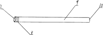
Fig. 2: the handle perspective view that is multi-purpose hammer of the present utility model:
The label declaration of parts in the schematic diagram:
1 tup, 2 nail nippings place, 3 external screw threads, 4 sawtooth, 5 saw blades
Anterior 7 handle front ends, 8 internal threads of 6 tups 9 handles 10 handle rear ends
(5) specific embodiment:
Below in conjunction with accompanying drawing, multi-purpose hammer of the present utility model is not only possessed the function of hammer for realize solving, and the optimal way that can work as the technical scheme that technical problem that saw uses takes is described further:
Its static structure: please join accompanying drawing: as shown in the figure, multi-purpose hammer of the present utility model mainly is made of tup 1, nail nipping place 2, external screw thread 3, sawtooth 4, saw blade 5, tup front portion 6, handle front end 7, internal thread 8, handle 9, handle rear end 10.Its major part saw blade 5 is selected for use by market.Its handle 9 is tube shapes, is material with the aluminium-alloy pipe, through the cutting processing manufacturing.Its tup 1 is many 1 groove shapes of general tup tail, is material with iron, through the casting processing and manufacturing.
In shape, structure and combination thereof, the total essential features of multi-purpose hammer of the present utility model and immediate prior art is: the screw position that is connected handle 9 is inserted in the hole site that has of tup 1, be combined into the fixed structure of hammer shape, function has been the fixedly effect of nail and so on.In shape, structure and combination thereof, the multi-purpose hammer of the present utility model technical characterictic different with immediate prior art is: the front position weldering of saw blade 5 is connected the interior position of groove of tup 1, be combined into the combination structure of horizontal "T"-shaped shape, function has been fixing effect.The front position of handle 9 is threaded in external screw thread 3 positions of tup 1, is combined into the screw connection structure of horizontal "T"-shaped shape, and function has been the effect of fixed handle.
Below by using method, further set forth the dynamic structure relation of this practical multi-purpose hammer: in use, when needs use the hammer function, principle according to machinery, the handle 9 of at first screwing on, be screwed to then and tightly move, grasp handle 9 work more then, thereby finish the task of using hammer.
In use, when needs use saw,, at first take out multi-purpose hammer, back out handle 9 then,, thereby finish the task of sawing of using again then with holding tup 1 according to the principle of machinery.So just realized that the solution of multi-purpose hammer of the present utility model not only possesses the function of hammer, and can work as the purpose of the technical problem that saw uses.
Realize that preferred plan of the present utility model is is material with aluminium-alloy pipe, iron, utilize the basic equipment of ironworking factory, take cutting, casting to produce by batch,, so just can realize the practical value and the economic worth of multi-purpose hammer of the present utility model better to supply the demand on social boundary.
Claims (2)
1. multi-purpose hammer, it is by tup (1), nail nipping place (2), external screw thread (3), sawtooth (4), saw blade (5), tup front portion (6), handle front end (7), internal thread (8), handle (9), handle rear end (10) constitutes, in shape, structure and be in conjunction with the total necessary technology of last the utility model and immediate prior art: the hole site insertion that has of tup (1) is connected the screw position of handle (9), the utility model is in shape, structure and in conjunction with last, the technical characterictic that is different from immediate prior art is: the weldering of the front position of saw blade (5) is connected position in the groove of tup (1).
2. multi-purpose hammer according to claim 1 is characterized in that the front position of handle (9) is threaded in external screw thread (3) position of tup (1).
Priority Applications (1)
| Application Number | Priority Date | Filing Date | Title |
|---|---|---|---|
| CN 02246676 CN2562940Y (en) | 2002-08-22 | 2002-08-22 | Multipurpose hammer |
Applications Claiming Priority (1)
| Application Number | Priority Date | Filing Date | Title |
|---|---|---|---|
| CN 02246676 CN2562940Y (en) | 2002-08-22 | 2002-08-22 | Multipurpose hammer |
Publications (1)
| Publication Number | Publication Date |
|---|---|
| CN2562940Y true CN2562940Y (en) | 2003-07-30 |
Family
ID=33717851
Family Applications (1)
| Application Number | Title | Priority Date | Filing Date |
|---|---|---|---|
| CN 02246676 Expired - Fee Related CN2562940Y (en) | 2002-08-22 | 2002-08-22 | Multipurpose hammer |
Country Status (1)
| Country | Link |
|---|---|
| CN (1) | CN2562940Y (en) |
Cited By (2)
| Publication number | Priority date | Publication date | Assignee | Title |
|---|---|---|---|---|
| CN102773553A (en) * | 2012-07-23 | 2012-11-14 | 太仓市旭达机械设备有限公司 | Multifunctional steel saw |
| CN108145659A (en) * | 2017-12-26 | 2018-06-12 | 芜湖荣基实业有限公司 | A kind of multifunctional hammer |
-
2002
- 2002-08-22 CN CN 02246676 patent/CN2562940Y/en not_active Expired - Fee Related
Cited By (2)
| Publication number | Priority date | Publication date | Assignee | Title |
|---|---|---|---|---|
| CN102773553A (en) * | 2012-07-23 | 2012-11-14 | 太仓市旭达机械设备有限公司 | Multifunctional steel saw |
| CN108145659A (en) * | 2017-12-26 | 2018-06-12 | 芜湖荣基实业有限公司 | A kind of multifunctional hammer |
Similar Documents
| Publication | Publication Date | Title |
|---|---|---|
| CN2562940Y (en) | Multipurpose hammer | |
| CN201244622Y (en) | Inlaid type hexagon cutting die | |
| CN2616344Y (en) | Multifunctional iron hammer | |
| CN2680415Y (en) | Convenient hammer | |
| CN2623418Y (en) | Hammer | |
| CN217432702U (en) | Quick processing equipment of U type staple bolt | |
| CN2570001Y (en) | Novel nailing device | |
| CN219466021U (en) | Special-shaped hook spanner | |
| CN2892322Y (en) | Riveting gun capable of collecting rivet bar | |
| CN216882115U (en) | Six-station drilling and tapping machine | |
| CN2732430Y (en) | Internal hexagonal wrench handhold | |
| CN2743085Y (en) | New type spanner | |
| CN2562910Y (en) | Multifunctional curve file | |
| CN2279985Y (en) | G-shaped clamp | |
| CN219924068U (en) | Copper scraps collection device | |
| CN2248794Y (en) | Agnail type nail | |
| CN2400212Y (en) | Regular polygon die | |
| CN212536383U (en) | Woodworking screw with high-strength structure | |
| CN220560360U (en) | Nut hand riveter convenient to replace | |
| CN2612515Y (en) | Multifunctional assembly tool | |
| CN2596095Y (en) | Slot nail | |
| CN215033308U (en) | Refrigerator compressor bottom plate riveting set | |
| CN2313681Y (en) | Sectional materials for pliers or the like | |
| CN2767737Y (en) | Nut with blind hole | |
| CN2399140Y (en) | Pipe thread hinge plate |
Legal Events
| Date | Code | Title | Description |
|---|---|---|---|
| C14 | Grant of patent or utility model | ||
| GR01 | Patent grant | ||
| C19 | Lapse of patent right due to non-payment of the annual fee | ||
| CF01 | Termination of patent right due to non-payment of annual fee |