CN2554638Y - Combined melt fibre distribution device - Google Patents
Combined melt fibre distribution device Download PDFInfo
- Publication number
- CN2554638Y CN2554638Y CN 02267767 CN02267767U CN2554638Y CN 2554638 Y CN2554638 Y CN 2554638Y CN 02267767 CN02267767 CN 02267767 CN 02267767 U CN02267767 U CN 02267767U CN 2554638 Y CN2554638 Y CN 2554638Y
- Authority
- CN
- China
- Prior art keywords
- fiber
- disk
- pallet
- top tray
- fine
- Prior art date
- Legal status (The legal status is an assumption and is not a legal conclusion. Google has not performed a legal analysis and makes no representation as to the accuracy of the status listed.)
- Expired - Fee Related
Links
- 239000000835 fiber Substances 0.000 title claims abstract description 44
- 238000009826 distribution Methods 0.000 title claims description 17
- 230000004927 fusion Effects 0.000 claims abstract description 22
- 238000005304 joining Methods 0.000 claims description 20
- 239000013307 optical fiber Substances 0.000 claims description 20
- 230000004888 barrier function Effects 0.000 abstract description 2
- 239000000428 dust Substances 0.000 abstract 1
- 230000002045 lasting effect Effects 0.000 abstract 1
- 230000002265 prevention Effects 0.000 abstract 1
- 239000012467 final product Substances 0.000 description 4
- 238000003466 welding Methods 0.000 description 3
- 210000000078 claw Anatomy 0.000 description 2
- 239000000155 melt Substances 0.000 description 2
- 230000003287 optical effect Effects 0.000 description 2
- 230000000694 effects Effects 0.000 description 1
- 238000009434 installation Methods 0.000 description 1
- 210000001503 joint Anatomy 0.000 description 1
- 238000004519 manufacturing process Methods 0.000 description 1
- 230000008018 melting Effects 0.000 description 1
- 238000002844 melting Methods 0.000 description 1
- 230000003014 reinforcing effect Effects 0.000 description 1
- 238000013024 troubleshooting Methods 0.000 description 1
Images


Landscapes
- Light Guides In General And Applications Therefor (AREA)
Abstract
The utility model relates to a combined fiber fusion distributing disk. The distributing disk comprises an upper tray, a lower tray and a fusing disk, wherein, the upper tray is folded on the lower tray, the fusing disk is disassembly arranged inside the lower tray, and a tail fiber disk fiber disk is arranged on the upper tray. A residual fiber disk fiber disk is arranged on the lower tray so as to store the surplus fiber, the fusing disk is positioned within an area surrounded by the side wall of the residual fiber disk fiber disk, and a fiber inlet and a fiber outlet are arranged on the residual fiber disk fiber disk. An upper cover is arranged on the upper tray to play the function of dust prevention. By adopting the utility model, the fiber is not required to be cutover again when the equipment is removed and the capacitance is expanded, thereby the barrier lasting time is reduced, the cutover investment is saved, and the universality and the interchangeability of the fiber fusion distributing disk among various fiber wired equipments are realized.
Description
Technical field
The utility model belongs to a kind of line connector, particularly relates to the molten fine distribution plate that adopts in a kind of optical fiber communication.
Technical background
At present, the molten fine distribution plate that telecommunication department ODF uses generally has two kinds, a kind of is that molten fine part is housed in a pallet, it is contained in the fiber termination box because its volume is bigger, in machine room occurring when relocation equipment, dilatation, again cutover causes obstacle to last length, increases extra cost during cutover.Another is that tow sides at same pallet are respectively equipped with fine part of dish and weld, though more preceding a kind of easy to use, dilatation or still must carry out cutover again when mobile.
Summary of the invention
Thereby the purpose of this utility model provides a kind of molten fine distribution plate of combined type that does not need cutover minimizing obstacle to last when resettlement and dilatation.
For achieving the above object, the utility model adopts following technical scheme: a kind of combined type melts fine distribution plate, and it comprises top tray, following pallet, fusion joining disk, and top tray is stacked in down on the pallet, fusion joining disk removably is contained in down in the pallet, and the tail optical fiber fiber disk is arranged on the top tray.
In order to take inventory unnecessary optical fiber pigtail, also be provided with surplus fine fiber disk on the following pallet, fusion joining disk is positioned at this surplus fine fiber disk sidewall institute region surrounded, and surplus fine fiber disk is provided with into fine mouthful and fiber mouth.
For dustproof, on top tray, be stamped loam cake.
After adopting such scheme, utilize the utility model welding distribution to operate at same workplace, easy to operate, can avoid the module upset simultaneously, optical fiber and tail optical fiber are caused damage.In conjunction with redesign to the light distributing equipment, optical fiber is fixed at the cabinet minimum distance place of disembarking, reduce optical cable baring length.The utility model adopts the combined integral design, thereby make it and to change arbitrarily at fiber termination box, width type fibre distribution frame, need not carry out welding again, having reduced obstacle lasts, save the cutover investment, also realized versatility and the interchangeability of molten fine distribution plate between various optical fiber distributing equipment.
Description of drawings
Fig. 1 is a whole diagrammatic cross-section of the present utility model;
Fig. 2 is the perspective view of loam cake;
Fig. 3 is the perspective view of top tray;
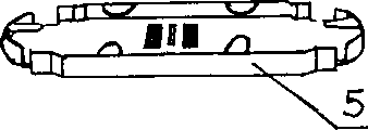
Fig. 4 is the perspective view of fusion joining disk;
Fig. 5 is the perspective view of following pallet
Fig. 6,7,8 is respectively front view, vertical view and the left view of top tray;
Fig. 9,10,11 is respectively front view, vertical view and the left view of pallet down.
Embodiment
As shown in the figure, the molten fine distribution plate of this combined type is made up of top tray 3, following pallet 4, fusion joining disk 5 and loam cake 1, top tray 3 is stacked in down on the pallet 4, following pallet 4 rear portions are provided with card 10, the front portion is provided with claw 11, top tray 3 front portions are provided with hole clipping 9, during assembling top tray 3 rear portions are inserted between following pallet 4 upper clamp slices 10 and following pallet 4 bodies, will play the claw 11 on the pallet 4 to push hole clipping 9 interior the getting final product that snap on the top tray 3 again.Certainly pallet also can adopt hinge connected mode or other connected mode that is fit to up and down.Loam cake 1 covers on top tray 3 and plays dustproof effect, and mounting means equally both can adopt snap-fit attachment, also can adopt hinge connected mode or other connected mode that is fit to.Also be provided with surplus fine fiber disk 8 on the following pallet 4, fusion joining disk 5 removably is contained in the zone that these surplus fine fiber disk 8 walls are surrounded, and surplus fine fiber disk 8 is provided with and advances with fusion joining disk 5 that fine mouthful and fiber mouth position are corresponding advances fine mouth and fiber mouth.The concrete mounting means of fusion joining disk 5 in following pallet 4 can be as shown in Figure 1, processing one and fusion joining disk 5 size corresponding grooves on the pallet 4 down, fusion joining disk 5 is placed directly in this groove forms wringing fit, when needing fusion joining disk 5 taken off, only need it is directly taken out in the groove and get final product.Also can velcro be set respectively, overlap mutually with velcro and get final product on fusion joining disk 5 bottom surfaces and following pallet 4 surfaces.Can also fusion joining disk 5 be fixed on down on the pallet 4 with screw, in the time of fusion joining disk 5 need being taken down from playing pallet 4, as long as screw is laid down.Also be provided with into fine mouthful and fiber mouth on fusion joining disk 5 sides.Top tray 3 is provided with tail optical fiber fiber disk 2, makes above tail optical fiber can be coiled in.Both sides, top tray 3 back are provided with two breach 6, behind fused fiber splice, make tail optical fiber draw and advance to be coiled in people's top tray 3 on the fine dish 2 of tail fiber disc from two breach 6 of top tray 3 from following pallet 4.Top tray 3 fronts are provided with adapter installing port 7, between adapter installing port 7 and the top tray 3 20~30 ° pitch angle is arranged, so just can the tilting installation of deflection certain angle when mounting adapter, avoided arc light direct projection human eye, also make tail optical fiber wire jumper natural torsion, be convenient to fine down.
During use if with optical fiber and tail optical fiber behind the molten fibre of butt joint on the fusion joining disk 5, tail optical fiber drawn to top tray 3 by pallet 4 down takes inventory unnecessary tail optical fiber, afterwards adapter is fixed in adapter installing port 7, can realize and outside jumper connection, simple and easy to do.Unnecessary optical fiber can be coiled on the surplus fine fiber disk 8.This knockdown molten fine distribution plate is owing to manage optical cable fibre core and tail optical fiber respectively on top tray 3 and following pallet 4, and fusion joining disk 5 adopts detachable form, need move or during dilatation at equipment like this, fibre melting disc 5 can be taken off from the molten fine distribution plate of combined type together with welding good optical fiber and tail optical fiber integral body, moving to new distributing frame place reloads the molten fine distribution plate of combined type and gets final product, so just avoided the cutover again when dilatation or resettlement, having significantly reduced obstacle lasts, also help simultaneously and install and troubleshooting, make attended operation more quick.Because independent mounting adapter, but reinforcing module barrier propterty are easy to change and adjust, the light wire jumper does not influence the adjacent fiber joint.The molten fine distribution plate of this combined type all is suitable for ordinary optic fibre banded, has satisfied different demands.Can make the sliding drawer formula during actual fabrication, operate so that take off from distributing frame.
Claims (3)
1, the molten fine distribution plate of a kind of combined type is characterized in that, it comprises top tray, following pallet, fusion joining disk, and top tray is stacked in down on the pallet, and fusion joining disk removably is contained in down in the pallet, and the tail optical fiber fiber disk is arranged on the top tray.
2, molten fine distribution plate as claimed in claim 1 is characterized in that, also is provided with surplus fine fiber disk on the following pallet, and fusion joining disk is positioned at this surplus fine fiber disk sidewall institute region surrounded, and surplus fine fiber disk is provided with into fine mouthful and fiber mouth.
3, molten fine distribution plate as claimed in claim 1 or 2 is characterized in that, is stamped loam cake on top tray.
Priority Applications (1)
| Application Number | Priority Date | Filing Date | Title |
|---|---|---|---|
| CN 02267767 CN2554638Y (en) | 2002-06-18 | 2002-06-18 | Combined melt fibre distribution device |
Applications Claiming Priority (1)
| Application Number | Priority Date | Filing Date | Title |
|---|---|---|---|
| CN 02267767 CN2554638Y (en) | 2002-06-18 | 2002-06-18 | Combined melt fibre distribution device |
Publications (1)
| Publication Number | Publication Date |
|---|---|
| CN2554638Y true CN2554638Y (en) | 2003-06-04 |
Family
ID=33733301
Family Applications (1)
| Application Number | Title | Priority Date | Filing Date |
|---|---|---|---|
| CN 02267767 Expired - Fee Related CN2554638Y (en) | 2002-06-18 | 2002-06-18 | Combined melt fibre distribution device |
Country Status (1)
| Country | Link |
|---|---|
| CN (1) | CN2554638Y (en) |
Cited By (3)
| Publication number | Priority date | Publication date | Assignee | Title |
|---|---|---|---|---|
| CN100360973C (en) * | 2005-03-29 | 2008-01-09 | 长飞光纤光缆有限公司 | Fiber-to-the-home ring laying branch fiber distribution method |
| CN100541251C (en) * | 2007-09-14 | 2009-09-16 | 南京普天通信股份有限公司 | A kind of integrated pallet that is used for optical fiber wiring system |
| CN101840039A (en) * | 2010-04-22 | 2010-09-22 | 深圳市华为安捷信电气有限公司 | Optical fiber terminal box |
-
2002
- 2002-06-18 CN CN 02267767 patent/CN2554638Y/en not_active Expired - Fee Related
Cited By (3)
| Publication number | Priority date | Publication date | Assignee | Title |
|---|---|---|---|---|
| CN100360973C (en) * | 2005-03-29 | 2008-01-09 | 长飞光纤光缆有限公司 | Fiber-to-the-home ring laying branch fiber distribution method |
| CN100541251C (en) * | 2007-09-14 | 2009-09-16 | 南京普天通信股份有限公司 | A kind of integrated pallet that is used for optical fiber wiring system |
| CN101840039A (en) * | 2010-04-22 | 2010-09-22 | 深圳市华为安捷信电气有限公司 | Optical fiber terminal box |
Similar Documents
| Publication | Publication Date | Title |
|---|---|---|
| CA2504678C (en) | Articulated high density fiber optic splice and termination shelf | |
| US5831211A (en) | Variable-type cable management and distribution system | |
| US5127082A (en) | Fiber optic patch panel | |
| US6356697B1 (en) | Optical fiber cable distribution shelf with pivotably mounted trays | |
| US6353696B1 (en) | Panel for managing jumper storage | |
| US5412751A (en) | Retrofittable multimedia patch management system | |
| CN102016674B (en) | Drawer structure with rack and pinion | |
| CN101521545B (en) | High-density optical fiber distributing hub | |
| JP3989853B2 (en) | Optical connection unit | |
| CN201047880Y (en) | Integrated disk component for optical fibre distributing frame | |
| JP3794540B2 (en) | Optical fiber extra length accommodation device | |
| CA2184595A1 (en) | Fiber distribution frame system | |
| JPH07198960A (en) | Optical fiber wiring device | |
| JP2008503771A (en) | Multi-position fiber optic connector holder and method | |
| KR102128540B1 (en) | Cable array bracket of internet data center | |
| CN2554638Y (en) | Combined melt fibre distribution device | |
| US8965166B2 (en) | Optical fiber adapter | |
| CN1212749A (en) | Modular furniture interconnection panel | |
| CN212933076U (en) | A modular high-density optical fiber distribution frame | |
| CN201166720Y (en) | Optical cable terminal box | |
| CN211180337U (en) | Distribution unit box and optical fiber distribution frame | |
| CN203241583U (en) | Splicing-adapting integrated tray | |
| CN210639318U (en) | Optical cable distribution frame supporting extended function | |
| CN210690902U (en) | Pull-out type distribution box integrating fiber melting and light splitting | |
| CN113671647A (en) | A high-density optical fiber distribution frame |
Legal Events
| Date | Code | Title | Description |
|---|---|---|---|
| C14 | Grant of patent or utility model | ||
| GR01 | Patent grant | ||
| C19 | Lapse of patent right due to non-payment of the annual fee | ||
| CF01 | Termination of patent right due to non-payment of annual fee |