CN2521590Y - Oil meter for oil pump - Google Patents
Oil meter for oil pump Download PDFInfo
- Publication number
- CN2521590Y CN2521590Y CN 01230107 CN01230107U CN2521590Y CN 2521590 Y CN2521590 Y CN 2521590Y CN 01230107 CN01230107 CN 01230107 CN 01230107 U CN01230107 U CN 01230107U CN 2521590 Y CN2521590 Y CN 2521590Y
- Authority
- CN
- China
- Prior art keywords
- valve body
- oil
- casing
- lid
- chamber
- Prior art date
- Legal status (The legal status is an assumption and is not a legal conclusion. Google has not performed a legal analysis and makes no representation as to the accuracy of the status listed.)
- Expired - Lifetime
Links
- 239000007788 liquid Substances 0.000 claims abstract description 5
- 239000012530 fluid Substances 0.000 claims description 15
- 238000005259 measurement Methods 0.000 claims description 15
- 239000012528 membrane Substances 0.000 claims 1
- 238000013461 design Methods 0.000 abstract description 7
- 238000007599 discharging Methods 0.000 abstract description 4
- 239000000314 lubricant Substances 0.000 abstract 1
- 239000000295 fuel oil Substances 0.000 description 24
- 239000003921 oil Substances 0.000 description 18
- 238000007789 sealing Methods 0.000 description 7
- 230000004888 barrier function Effects 0.000 description 4
- 238000000034 method Methods 0.000 description 4
- 238000000605 extraction Methods 0.000 description 3
- 239000000446 fuel Substances 0.000 description 3
- 230000033001 locomotion Effects 0.000 description 3
- 230000007246 mechanism Effects 0.000 description 3
- 230000008569 process Effects 0.000 description 3
- 238000012360 testing method Methods 0.000 description 3
- 239000004411 aluminium Substances 0.000 description 2
- XAGFODPZIPBFFR-UHFFFAOYSA-N aluminium Chemical compound [Al] XAGFODPZIPBFFR-UHFFFAOYSA-N 0.000 description 2
- 229910052782 aluminium Inorganic materials 0.000 description 2
- 230000008676 import Effects 0.000 description 2
- 238000009434 installation Methods 0.000 description 2
- 238000012423 maintenance Methods 0.000 description 2
- 210000003205 muscle Anatomy 0.000 description 2
- 229920001343 polytetrafluoroethylene Polymers 0.000 description 2
- 230000009467 reduction Effects 0.000 description 2
- 239000004215 Carbon black (E152) Substances 0.000 description 1
- 208000034189 Sclerosis Diseases 0.000 description 1
- 239000004809 Teflon Substances 0.000 description 1
- 229920006362 Teflon® Polymers 0.000 description 1
- 230000006978 adaptation Effects 0.000 description 1
- 230000005540 biological transmission Effects 0.000 description 1
- 238000005056 compaction Methods 0.000 description 1
- 239000012141 concentrate Substances 0.000 description 1
- 230000008878 coupling Effects 0.000 description 1
- 238000010168 coupling process Methods 0.000 description 1
- 238000005859 coupling reaction Methods 0.000 description 1
- 230000002950 deficient Effects 0.000 description 1
- 230000000694 effects Effects 0.000 description 1
- 238000005516 engineering process Methods 0.000 description 1
- 230000006870 function Effects 0.000 description 1
- 229930195733 hydrocarbon Natural products 0.000 description 1
- 150000002430 hydrocarbons Chemical class 0.000 description 1
- 230000006872 improvement Effects 0.000 description 1
- 238000002955 isolation Methods 0.000 description 1
- 238000004519 manufacturing process Methods 0.000 description 1
- 238000000465 moulding Methods 0.000 description 1
- 230000007935 neutral effect Effects 0.000 description 1
- 230000010349 pulsation Effects 0.000 description 1
- 239000000523 sample Substances 0.000 description 1
- 229920002994 synthetic fiber Polymers 0.000 description 1
Images


Landscapes
- Measuring Volume Flow (AREA)
Abstract
The utility model relates to a lubricant pump consumption meter, the design of the utility model is that the liquid enters into a gauge table from the bottom, and is measured when passing upwards through the gauge table casing, and further is discharged from the top of the gauge table. The gauge table shortens the required flowing route of the liquid to the gauge table, and is possible to regulate the gauge table via converting the discharging outlet position according to the assembling environment. Moreover, employing the gauge table to mount directly to the oil outlet of a pump is possible.
Description
The utility model field:
The utility model relates to gauging table, specially refers to the special-purpose gauging table of the measurement dispensing fuel oil of using in the refuelling station (for example gasoline).The utlity model has a kind of scheme, make the disposable center oil suction chamber of flowing through of fuel oil, once by one in the four measuring chamber, flow to then then by the client of dispensing.This finishes by a rotary valve, and this valve all works flowing into and flow out all four measuring chambers.Needs when this structure allows the oil-out position according to the installation pump are placed.
Background technology:
Be by with plunger front-rear reciprocation movement in cylinder for a long time, whenever finish measuring apparatus that stroke measures a quantitative flow and realize fuel oil (for example gasoline) dispensing.The problem that past exists, be exactly these devices be very accurate only in a suitable limited portion of its operating rate gamut.One of target of the present utility model is exactly that gauging table keeps the gamut precision when enlarging the speed range significantly.Another problem is that this type fuel-metering device is the device of the time of the sort of maintenance measuring accuracy above the rational mission life of equipment.Wearing and tearing serious problems always, when equipment is made very accurate, equipment just has functional issues---and too responsive to fuel oil booty and temperature variation and so on situation.Therefore in fact all devices all is to compromise between precision, life cycle and application function.
(refuelling station) is increasing along with the service station, and is designed to many automobiles and refuels simultaneously, also brings a more and more difficult problem, is exactly how to keep simultaneously and improve precision, make equipment compacter, more simplify and lighter.It is also important that to make equipment can adapt to the space requirement that is assembled to different pump frames, for the equipment applicability, this is very important too.Therefore, be starved of and importantly design a kind of device can the special-purpose installed device of very fast adaptation.
General introduction of the present utility model:
The utility model provides a kind of gauging table first, comprises a kind of mechanism design, can address the above problem simultaneously and defective, is a kind of obviously compacter, light on weight than most of measuring apparatus simultaneously, thereby is applicable to the gauging table of fuel oil ration centre.
It is finished through the following steps: directly with fuel oil with the pump pump that makes progress, make oil flow into its center cavity from bottom of device, make progress through rotary valve from center cavity, the exhaust chamber top, like this as the single cycle of its process, open four chambeies one by one, in each chamber, be mounted a reciprocating measurement plunger.The motion of valve is carried out in each chamber continuously, opens the supply of fuel oil under pressure, and sealing is supplied with then, and gets through the dispensing pipe, and the fuel oil in this dispensing pipe is discharged with heterodromous cylinder plunger, is connected to outlet then.Make fuel oil have only a passage like this, and have only single passage to have the chamber of measuring plunger by gauging table.This device is discharged tested fuel oil from the top.Simultaneously, the gauging table structure is such: the one-tenth of the seal designs between the part of motion keeps the surface contact and forms sealing with exerting pressure mutually, this seal only forms sealing where necessary, because high pressure always remains on seal element and is adjacent to that side that must seal, this is important to keeping precision.
This gauging table design also makes the escape hole position be adapted to applied special-purpose installation environment becomes possibility.This realizes by the location about that the gauging table oil-out is set when mounted, in the time of before it is secured on the gauging table casing, rotates closing cap to requiring the position.
Brief description of drawings:
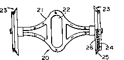
Accompanying drawing 1 is the gauging table front view.
Accompanying drawing 2 is gauging table upward views.
Accompanying drawing 3 is oblique views of each isolation of components state of gauging table.
Accompanying drawing 4 is front views of measuring plunger.
Accompanying drawing 5 is to begin oil extraction and oppositely measure the cut-open view that the chamber begins gauging table when oil-filled when left side measuring chamber.
Accompanying drawing 6 is along Fig. 5 same level but in order to represent the partial sectional view of part relation.
Accompanying drawing 7 is the partial bottom view along the base of the rotary valve part of Fig. 3 VII-VII plane incision.
Accompanying drawing 8 is front elevations of rotary valve part.
Accompanying drawing 9 is upward views of rotary valve part.
Accompanying drawing 10 is the cut-open views along the rotary valve part on Fig. 8 X-X plane.
Accompanying drawing 11 is the sectional views along Fig. 8 XI-XI plane.
Accompanying drawing 12 is the sectional views along Fig. 5 XII-XII plane.
The detailed description of most preferred embodiment:
See figures.1.and.2, gauging table 10 has a casing 11, wherein have 4 measurement chambeies 12 to be separated by 90 ° and place, and each is all protruding from center oil suction chamber 13, and tested fluid is imported by oil-in 14 under pressure in center oil suction chamber 13.
In casing 11,2 plungers and connecting link assembly 19 and 19a (they are placed with the vertical mutually Fig. 5 of opinion) are arranged, each assembly has 2 identical stopper head 23 (see figure 4)s, each act on a pair of being inverted (to) measure in the chamber 12.Two stopper heads 23 of one centering are secured to the two ends of a plunger actuator or bar 21, and other stopper head is secured to bar 21a (Fig. 5).Plunger actuator or bar 21 are at its center, have one that extend, horizontal, slit opening 22, each actuator has a stature assembly on every end, and each assembly has an end cap 24, and its diameter is slightly less than embedded chamber diameter, and each assembly has a seal element 25, its periphery forms slipper seal towards the casing center curvature with the wall of measuring chamber 12.The sealing part is bearing on its inside surface by cover plate 26, and the seal opening can be a kind of suitable synthetic material, and selection is according to survey fluid type decided to a great extent.
Center slit opening 22 traverses the central shaft of bar or actuating body, and surrounds a bearing 27, and bearing is contained in main shaft 28 ends (referring to Fig. 5) that are positioned at casing 25 centers prejudicially.The 2nd bearing 27a, with bearing 27 on same axle, also be secured on the eccentric pin 29, this 2nd bearing is embedded in the translot of the second bar 21a that places perpendicular to first actuator.Second actuator loaded onto 2 plungers of measuring the chamber, and as described above being placed to of plunger is in 90 °.Because all 4 plungers are with the such actuating of universal drive device, their work is coordinated.Main shaft 28 is positioned at the shell center, extends out from oil-in, and supports (referring to Fig. 5) with bearing 29 and 29a.
One middle section is arranged at casing 11 tops, four identical mouths 33 are arranged therebetween, make identical spaced radial is outwards arranged, and concentrate on central passage 34 (Fig. 5,6 and 7) around, main shaft 28 is upward through central opening, each mouthfuls 33 is communicated with casing upper channel 35, and this channel parallel is in certain measurement chamber 12 and be positioned at above it.As quilt typical case in Fig. 5 and 6 is illustrated.The pipeline 35a that each passage forms by the outside bypass near the epicranial plate 39 of measuring the end, chamber measures chamber 12 with certain and is communicated with (referring to Fig. 5).We will appreciate that: the structure of mouth, passage and pipeline is identical to four measuring chamber 12.
Be seated in the casing top and aim at main shaft 28, and central opening 34 is to have mouthful and the cover plate 36 (referring to Fig. 7) of opening 33a, size, shape and the position corresponding (Fig. 5) of its size, shape and position and a certain casing upper shed or mouth 33.
What be seated cover plate is valve body (valve member) 40 (referring to Fig. 5 and Fig. 6), the easiliest in Fig. 9 finds out that there are 2 openings 41 and 42 in the bottom surface of valve body.Valve inner is divided into one with muscle 45 and is connected to the suction chamber 43 of opening 42 and the discharge side 44 (Fig. 9) that is connected to opening 41, the moulding of this muscle makes the chamber be placed on diametric(al) toward each other, separate with gapless plane 46 of a pair of diametric(al) and 46a on every side, wherein each face all has length around one to be slightly larger than the length (Fig. 7) of certain opening 33a on the cover plate 36, and this just allows valve body the charging and discharging of control survey chamber 12 when being rotated.Valve body has the central opening 47 of a main shaft 28, and forces it to rotate with the axis with the key 48 that is embedded in groove 47a (Fig. 9 and 12) (Fig. 5 and 6).
Suck the fluid that is measured at suction chamber 43, this fluid is from oil-in 13 central passage 34 (Fig. 5,6 and 7) of flowing through, with process passage 35 and 35a oil is discharged to metering or measures chamber 12, and to being communicated with the outer end in a certain measurement chamber 12 with suction chamber 43 through ports or one of opening 33 and 33a (seeing Fig. 6 left-hand side).Because valve body 40 is driven, oil suction chamber 43 will be connected to each oil-in 33 (Fig. 6) in four measuring chamber 12 successively.Similarly, the circular row oil pocket 44 that surrounds valve body 40 will be connected to be positioned at relative on the diameter one just in oil-filled measurement chamber.Just the fluid in the chamber 12 of oil extraction will flow through valve body 40 by the circular channel 44 that closing cap 66 forms, to oil-out 51 and thus mouthful to user (Fig. 6 and 12).
Contrast Fig. 8 and Figure 10 can find out that valve 40 has 2 blind holes 53, and it does not lead to valve.The purpose in these holes is in order to alleviate the valve body quality and to keep the equipment wall thickness to process unanimous on the wholely.Valve 40 also has 2 holes 54, and these and hole 55 guarantee that oil-feed is arranged, and so just guarantee that tool has top pressure on sunk area 62, pressure coil 60.This circle has accurate dimensions, and to transmit downward hydraulic coupling, this power always has very big difference with the power that upwards acts on valve body 40 to valve body 40, and is no matter much by the flow velocity of gauging table.In dispose procedure very slowly, when pressure divergence low and when gauging table time spent not, the oblique spring 61 of Jia Zaiing has improved contacting of pressure coil 60 and valve body 40 and valve body 40 and 36 of cover plates during low-down transmission slightly.This structure well contacts for element 60,40 and 36 faying surfaces provide continuously, has guaranteed measuring accuracy on very wide flow range.
Importantly perforate 41 and 42 each all have certain around (circular arc) length, for example during measuring the chamber and charging and discharging oil, each such opening all will be communicated with the opening 33a of two vicinities.Like this, gauging table has been realized charging and discharging continuously of fluid, has eliminated the pulsation that each mouthful works independently and cause.
Valve body upper end or small end are close to pressure coil 60 (Fig. 5 and Fig. 6).Spring 61 acts on pressure coil and is close to cover plate 36 fully to keep valve body 40.When valve body compaction pressure circle, there is an inner chamber 62 the valve body upper end, and this chamber 62 is communicated with suction chamber 43, around main shaft 28, hydraulic pressure is provided for the seal of 36 of valve body 40 and valve seat or cover plates with spring 61 like this.
The upper end of pressure coil 60 is secured to the inboard of barrier film 65, and the outside of barrier film is fastened to closing cap 66 (Figure 12) with clamping ring 67 and screw 68.The inboard of barrier film is fastened to (Fig. 5) on the pressure coil 60 with endless member 69 and fastener 70.Be communicated with central passage in the valve body at the inner chamber 62 of barrier film top.The diameter that is subjected to pressure coil 60 upper surfaces of input pressure equals to stand the upwards lower surface area size (diameter) of the valve body 40 of applied pressure at least, and the downward pressure of spring 61 requirements is wanted effective sealing can be provided at least like this.Stretch out from covering 66 top main shaft 28 upper ends, and around in the place of stretching out this lid sealed 75 seal seal 75 usefulness cover plates 77 and screw 78 maintenances (Fig. 1 and Fig. 5).The outer end of main shaft is connected with the device that can monitor rotation, has so just produced the total flow record that flows through gauging table.
Gauging table is by dispensing fuel oil operation, and the pressure of the fuel oil that advances from pump provides unique power of operating gauging table with the difference that acts on gauging table and the back pressure between (fuel oil is dispensing thus) is chewed in oil extraction.Therefore, fuel oil is arranged to client's speed big more, and pressure reduction is big more, and it is fast more that gauging table walks.
The oil that enters gauging table charges into fully through oil-in 14 and measures the chamber and around the casing core between the central passage around the main shaft 28, as long as fuel oil dispensing valve or chew and open, the outlet side pressure in a certain measurement chamber will reduce, when not having fuel delivery, destroyed the pressure equilibrium of setting up, this pressure reduction outwards promotes the plunger in a certain measurement chamber with the pressure that allows to enter oil-in 14, is connected to oil-out then, has so just begun metrological operation.When carrying out, fuel oil, because of it is directly to enter certain to measure the chamber from that chamber and is discharged to outside the gauging table from there only once by center cavity.The result of this structure is compacter significantly than known congenerous device, and this improvement importance is: whenever, have at least a measurement chamber to be communicated with, and be communicated with oil-in in diametric(al) measurement chamber in contrast with oil-out.This for prevent gauging table malfunctioning be necessary because under suitable environment, be required to separate with whole four measuring chambeies at hydraulic fluid port fluid.
By import the fluid that is measured in the bottom, discharge fluid from the measurement chamber at gauging table top, and relatively near gauging table central authorities, just may gauging table design regulate any several directions of discharge (being preferably 4) one of the flow of (part).In this former gauging table is impossible, because the relation on the periphery of the fuel oil import and export of gauging table is unalterable.What is more, the invention a kind ofly can not install adjusting type very fast and that carry out at an easy rate by parts peculiar and instrument.Gauging table of the present invention to do all be exactly removable screw 78 (Fig. 1), keep the screw of closing cap 66 and twist-off cap to place oil-out 51 to the position that requires.As shown with explanation like that, when closing cap 66 only can have four positions, by the quantity that increases bolt 78 allow lid be placed on any one 1/6, or 1/8 position, the applicability that the utility model provides has increased.When modernized fuel oil ration centre was installed, this was very important, because their complicacy and size leave very little space to coordinate the necessary complicated comb of directed fuel-displaced gauging table.It has not only simplified equipment, has also reduced manufacturing complicacy and stock control greatly.
Another characteristics of the remarkable contribution of versatility of the present utility model aspect are: fuel oil is introduced from gauging table bottom centre through oil-in 14.This design allows gauging table directly to be installed in the oil-out of pump.So not only reduce cost, can also largely reduce the cost of all components and required personnel cost is installed.Also help headspace by tightening complete machine significantly.
This utility model provides high precision in the wide range fuel flow rate, add that the present invention controls the requirement that fuel oil flows to gauging table, makes gauging table even can be suitable for having under the environment of high-precision requirement more.In approximate 5 gallon per minute in 20 gallon per minute gamuts, the variable quantity of whole precision is less than 0.0590%, and on the great majority point of this scope, all be far smaller than this variable quantity, even in the ultimate value of pump work scope, maximum error also is not more than 0.2%.
The mechanism of gauging table uses fuel pressure that enough sealings are provided.Because valve body 40 is being pressed by cover plate 36, by spring 61 and input pressure acting in conjunction, spring 61 necessary applied pressures, in fact can be little to the degree of influence to the pressure of cover plate 36 sealings, so just reduced the power that must add in advance, and it is stop the rotation of valve body 40, thereby make valve more responsive, thereby more accurate to condition of work.Reduced friction and wear simultaneously, this helps valve and can accurately respond to the wide range condition of work.
Certain chamber is equipped with the stroke 20 of device 110 to regulate certain plunger, and this is a fine setting, and is used for compensating the variable quantity between a gauge assembly and another assembly.Since main shaft 28 turns around, all four plungers collect the fuel oil total amount of surveying be sub-fraction in the bodge that the dispensing fuel oil adopts, so, the stroke effect in plunger is to adjust whole gauging table output accuracy effectively.When employing was of the present invention, this scheme was easily, and this is not a part of the present invention.
Certain epicranial plate 39 has monitors the device that the oil liquid temperature that is measured is used.Thus, epicranial plate 39a has a wheel hub 120 (Fig. 1 and Fig. 3) that has diplopore 121.Preferably these and stroke adjuster spare be on same epicranial plate, but this is dispensable.For the fuel oil oil-in is provided, opening 121 is provided, in operate as normal, one is inserted into and other is usually installed a temperature sensing probe and puts in oil circuit, as measure the fuel oil, sensor measures its temperature and the capacity by auxiliary electronic equipment (not being content of the present invention) and shows all the time price, and price presets oily temperature setting value with reference to one by what standard adopted.
Second opening is a test pit that regularly uses during auto thermal compensation (ATC) precision of tester scale.Certain observer inserts test pit with thermometer, and records the oil temperature of gauging table test period, and its result and ATC system standard are compared.
The described best specific embodiment of implementing of utility model has been arranged, just can understand various variation of the present utility model, otherwise depart from the principle of the invention.This variation will be included in the after this appended right, unless these rights are shown as other meaning by their language table.
Claims (7)
1. one kind is used for following gauging table that flows through the quantity of liquid of gaging pressure, comprise a casing, it is characterized in that, described casing has a center cavity that inflow entrance is arranged in the bottom, with four equal sizes become the measurement chamber of a circle in described center cavity placed around, they extend radially out thus, a turning axle is concentric with the central axis in described chamber, this chamber center line is perpendicular to described measurement chamber central axis, each is measured a reciprocating plunger is installed in the chamber, and whole described plungers is connected to the crank device of described excentric shaft; Has the described casing that a circular valve is installed at its top, valve body is fastened on the described main shaft of rotation thus, the valve body of cap seal mouth of being fixed has a radially-protruding outside oil-out, and described lid has formed the circular passage of fluid around the described valve body that is communicated with described oil-out; A separating pipe is measured the chamber with each separately and is communicated with described valve body, described valve body has a first passage, in order to from described center cavity oil suction, described first passage is linked to each other with each described conduit one by one by described valve body and forms, can enter each by conduit and measure the chamber, described valve body has a second channel of isolating with described first passage, this second channel is communicated with each conduit one by one from alleged measurement chamber oil suction, discharge oil-out then, when described valve body is driven, it enters fluid and enters each measurement chamber one by one, be discharged to a described escape hole of accurately measuring oily quantity one by one thus.
2.. the gauging table described in right 1 is characterized in that described oil-in is coaxial with described valve body.
3. the gauging table described in right 1 is characterized in that stage clip is installed in the described described lid, and is crushed between described lid and the described valve body in order to valve body is against on the described casing.
4. the gauging table described in right 3, it is characterized in that the membrane device that comprises a complexity seals described spring, and the fluid in it and the circular passage is separated, the circular passage surrounds described valve body, here, can occupy described spring and interior area from the flow through fluid of central opening of described valve body of described center cavity, and described valve body is against on the described casing with the spring acting in conjunction.
5. the gauging table described in right 1 is characterized in that the described base portion that is positioned on the described casing that is stamped, and described base portion is symmetrical in central shaft, and described lid surrounds described valve body, and leaves the space each other diametrically; The unified removable fastening means of reserving is in order to be fastened to base portion with lid, this base portion is covered central shaft relatively and is symmetrically distributed, lid can be secured on the casing along the oil-out axis thus, the axis of escape hole circumferentially extending in a certain (be located on the casing, as many) opening with radial position, along this axis, lid can be aimed at the oil suction device, and this device is used for lid is fastened to casing.
6. the gauging table described in right 5 is characterized in that having four equidistant openings to offer the securing member of lid and casing, and lid can be positioned to any one described oil-out of four circumferential positions thus.
7. the gauging table described in right 1, it is characterized in that being positioned at the base of on the casing, described lid and be attached to device on the casing about described main shaft symmetry, described thus oil-out can be located by described lid is reset on the described casing at circumferencial direction.
Priority Applications (1)
| Application Number | Priority Date | Filing Date | Title |
|---|---|---|---|
| CN 01230107 CN2521590Y (en) | 2001-07-06 | 2001-07-06 | Oil meter for oil pump |
Applications Claiming Priority (1)
| Application Number | Priority Date | Filing Date | Title |
|---|---|---|---|
| CN 01230107 CN2521590Y (en) | 2001-07-06 | 2001-07-06 | Oil meter for oil pump |
Publications (1)
| Publication Number | Publication Date |
|---|---|
| CN2521590Y true CN2521590Y (en) | 2002-11-20 |
Family
ID=33644797
Family Applications (1)
| Application Number | Title | Priority Date | Filing Date |
|---|---|---|---|
| CN 01230107 Expired - Lifetime CN2521590Y (en) | 2001-07-06 | 2001-07-06 | Oil meter for oil pump |
Country Status (1)
| Country | Link |
|---|---|
| CN (1) | CN2521590Y (en) |
Cited By (2)
| Publication number | Priority date | Publication date | Assignee | Title |
|---|---|---|---|---|
| CN105672984A (en) * | 2016-03-17 | 2016-06-15 | 叶侃 | A Constant Volume Single Well Metering Structure |
| CN109073492A (en) * | 2016-04-27 | 2018-12-21 | 北陆电气工业株式会社 | Pressure sensor apparatus |
-
2001
- 2001-07-06 CN CN 01230107 patent/CN2521590Y/en not_active Expired - Lifetime
Cited By (4)
| Publication number | Priority date | Publication date | Assignee | Title |
|---|---|---|---|---|
| CN105672984A (en) * | 2016-03-17 | 2016-06-15 | 叶侃 | A Constant Volume Single Well Metering Structure |
| CN105672984B (en) * | 2016-03-17 | 2018-10-16 | 叶侃 | A kind of constant volume type one-well metering structure |
| CN109073492A (en) * | 2016-04-27 | 2018-12-21 | 北陆电气工业株式会社 | Pressure sensor apparatus |
| CN109073492B (en) * | 2016-04-27 | 2021-03-12 | 北陆电气工业株式会社 | Pressure sensor device |
Similar Documents
| Publication | Publication Date | Title |
|---|---|---|
| CN1081726C (en) | Cylinder lubrication unit for multicylinder internal combustion engine, and method for controlling dosage from cylinder lubrication unit | |
| US6412338B2 (en) | On-board rotational viscometers | |
| US3134508A (en) | Fluid metering method and apparatus | |
| CN101863195B (en) | Automobile third-generation hub unit assembly line | |
| CA1202198A (en) | Engine cold testing | |
| CN2521590Y (en) | Oil meter for oil pump | |
| US2210067A (en) | Fuel feeding and distributing apparatus for oil burning engines | |
| CN100587439C (en) | Method and device for measuring the leakage of injection systems, especially for internal combustion engines of motor vehicles | |
| US4491248A (en) | Free piston volumetric measuring device and method for measuring wherein the piston has a specific gravity approximately matched to the liquid being dispensed | |
| EP1163501B1 (en) | On-board rotational viscometers | |
| CN201703457U (en) | Assembly line for automobile third-generation wheel hub unit | |
| CN206470062U (en) | A kind of mechanism for testing and test platform of the side-mounted changeable air valve of internal combustion engine | |
| US5094106A (en) | Liquid meter for fuel pumps | |
| CN103298732B (en) | Fluid meter, multi-fluid meter components, and fuel distribution unit for adding fuel to vehicle | |
| US2106651A (en) | Piston meter | |
| CN1131381C (en) | Zero point position-determining mechanism for pressurized fluid-driven apparatus | |
| US2116265A (en) | Multipiston meter | |
| GB2188162A (en) | Viscometer | |
| CA1112900A (en) | Fuel volume meter | |
| US4250748A (en) | Fuel volume meter | |
| CN203190917U (en) | An apparatus used for measuring the amount of the valve lift of an engine | |
| US1893595A (en) | Meter | |
| US7263900B2 (en) | Volumetric flow metering device | |
| US2499784A (en) | Variable capacity lubricating pump | |
| CN208998864U (en) | A kind of flow-meter for piston type oil feeder |
Legal Events
| Date | Code | Title | Description |
|---|---|---|---|
| C14 | Grant of patent or utility model | ||
| GR01 | Patent grant | ||
| C17 | Cessation of patent right | ||
| CX01 | Expiry of patent term |
Expiration termination date: 20110706 Granted publication date: 20021120 |