CN2420734Y - Modular Battery Holder - Google Patents
Modular Battery Holder Download PDFInfo
- Publication number
- CN2420734Y CN2420734Y CN00231409.6U CN00231409U CN2420734Y CN 2420734 Y CN2420734 Y CN 2420734Y CN 00231409 U CN00231409 U CN 00231409U CN 2420734 Y CN2420734 Y CN 2420734Y
- Authority
- CN
- China
- Prior art keywords
- battery
- elastic portion
- battery tray
- battery holder
- modularity
- Prior art date
- Legal status (The legal status is an assumption and is not a legal conclusion. Google has not performed a legal analysis and makes no representation as to the accuracy of the status listed.)
- Expired - Lifetime
Links
Images


Classifications
-
- Y—GENERAL TAGGING OF NEW TECHNOLOGICAL DEVELOPMENTS; GENERAL TAGGING OF CROSS-SECTIONAL TECHNOLOGIES SPANNING OVER SEVERAL SECTIONS OF THE IPC; TECHNICAL SUBJECTS COVERED BY FORMER USPC CROSS-REFERENCE ART COLLECTIONS [XRACs] AND DIGESTS
- Y02—TECHNOLOGIES OR APPLICATIONS FOR MITIGATION OR ADAPTATION AGAINST CLIMATE CHANGE
- Y02E—REDUCTION OF GREENHOUSE GAS [GHG] EMISSIONS, RELATED TO ENERGY GENERATION, TRANSMISSION OR DISTRIBUTION
- Y02E60/00—Enabling technologies; Technologies with a potential or indirect contribution to GHG emissions mitigation
- Y02E60/10—Energy storage using batteries
Landscapes
- Battery Mounting, Suspending (AREA)
Abstract
Description
本实用新型涉及一种电池座,特别是针对可适用在以干电池供应电源的各种消费性电子产品上,且经特殊的模组化结构设计而使其能更简易、快速且准确稳固地完成组装作业,足以有效大幅降低生产成本与提高产品品质所研制发展的一种模组化电池座的新型创作。The utility model relates to a battery holder, especially for various consumer electronic products that are powered by dry batteries, and can be completed more easily, quickly, accurately and stably through a special modular structure design. The assembly operation is enough to effectively and greatly reduce the production cost and improve the product quality. It is a new creation of a modular battery holder developed.
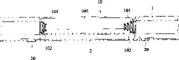
如图1所示,一般以干电池为主要或各用电源的各种消费性电子产品传统上,在其机体的机壳1适当处预设成型有具电池槽100的电池座10,电池槽100二端,再分别组设有金属弹簧或弹片形态的导电元件101,以供能分别与电池的正、负电极相接触,而该二导电元件101则必需再依赖导线牵引,或是如图2所示的锡焊方式电性连接至电路板2的预设对应电路接点20上才能完成导电回路。As shown in FIG. 1 , in general, various consumer electronic products that use dry batteries as the main or various power sources traditionally have a
前述的传统电池座10由于成型在机壳1上,而二导电元件101却得借导线或焊接方式预设在电路板上,而后当将电路板2结合在机壳1上时,导电元件101才能穿出于电池槽100二端的预没透孔102定位,也因此在生产线上往往为了导线的牵线理线,或是难以对导电元件101过锡炉焊接等的多次繁琐加工作而浪费作业人员的劳力,不但相当耗时费工,因此提高整体生产成本负担,并且在组装精确度上亦不易控制,尤其导电元件101与电路板2间的组接构造并不强固,故更易因不当拉扯或剧烈震动而异致松脱,致接触不良,严重影响产品的品质。The aforementioned
本实用新型的目的是提供一种模组化电池座,它能提供接触电池正、负级的导电元件,以特殊方式预先组合在独立的一电池座上,而予以模组化,使该电池座当安装于电路板上的同时,能一并使导电元件与电路板间达成稳固的电性连接。The purpose of this utility model is to provide a modularized battery holder, which can provide conductive elements contacting the positive and negative poles of the battery, which are pre-assembled on an independent battery holder in a special way, and then modularized, so that the battery When the seat is installed on the circuit board, it can also achieve a stable electrical connection between the conductive element and the circuit board.
本实用新型的目的是这样实现的:它包括一电池座,二定位件及二导电元件,其中电池座具有可容纳电池的电池槽;定位件设置在电池座相对于电路板预设跳线接点处;二导电元件各具有相连的第一弹性部与第二弹性部,其中第一弹性部配置放电池槽端部,而第二弹性部则配置放电池座底部的定位件处。The purpose of this utility model is achieved in this way: it includes a battery holder, two positioning parts and two conductive elements, wherein the battery holder has a battery groove that can accommodate the battery; place; each of the two conductive elements has a connected first elastic portion and a second elastic portion, wherein the first elastic portion is configured at the end of the battery slot, and the second elastic portion is configured at the positioning member at the bottom of the battery holder.
所述导电元件由单一金属丝所折制成型,并使其第一弹性部与第二弹性部均成型为螺旋弹簧形态。The conductive element is formed by folding a single metal wire, and the first elastic part and the second elastic part are formed into a coil spring shape.
所述定位件可为螺丝,而电池座与电路板相对应处则分设有螺孔。The positioning member can be a screw, and the corresponding part of the battery holder and the circuit board is provided with a screw hole.
所述电池槽二端为挡壁,而电池槽邻接挡壁处开设有透孔。The two ends of the battery tank are retaining walls, and the battery tank is provided with a through hole adjacent to the retaining wall.
所述导电元件的第一弹性部与第二弹性部间另具有定位凸臂,而池槽二挡壁底部朝壁体内则开设成插槽。There is also a positioning protrusion between the first elastic part and the second elastic part of the conductive element, and a slot is opened at the bottom of the second barrier wall of the tank towards the wall.
所述定位凸臂顶端另朝外凸出成型有卡凸部,而挡壁插槽顶部则朝外开设有顶口。The top of the positioning arm protrudes outwards to form a locking protrusion, and the top of the retaining wall slot opens outwards with a top opening.
由于采用上述方案:使其组装制程能更为省时省工、且产品妥善率更高。Due to the adoption of the above solution: the assembly process can save time and labor, and the product yield is higher.
为使贵审查委员能更进一步了解本实用新型为达成预定目的所采取的技术、手段及功效,兹举一较佳可行的实施例并配合图式详细说明如后,相信本实用新型的目的、特征与优点当可由此得一深入且具体的了解。In order to enable your review committee to further understand the technology, means and effects of the utility model to achieve the intended purpose, hereby give a preferred and feasible embodiment and describe it in detail with the drawings. It is believed that the purpose of the utility model, Features and advantages should be able to gain an in-depth and specific understanding.
图1为习知一种电池座结构的分解立体图。FIG. 1 is an exploded perspective view of a conventional battery holder structure.
图2为第一图习知电池座组合结构的轴向剖面侧视图。Fig. 2 is an axial sectional side view of the conventional battery holder assembly structure in Fig. 1 .
图3为本实用新型分解结构的立体图。Fig. 3 is a perspective view of the exploded structure of the utility model.
图4为本实用新型组合结构的立体图。Fig. 4 is a perspective view of the combined structure of the utility model.
图5为图4的A部分结构的放大立体图。FIG. 5 is an enlarged perspective view of the structure of part A of FIG. 4 .
图6为本实用新型组合结构的轴向剖面侧视图。Fig. 6 is an axial sectional side view of the composite structure of the present invention.
请参阅图3、4所示,本实用新型的模组化电池座主要适用于以电池为主要、或备用电源的各种消费性电子产品上,而可以独立模组形态预先组装在其机体内的电路板3上,再结合机壳以完成组装,该模组化电池座结构主要包括有一电池座4与二导电元件5,其中:Please refer to Figures 3 and 4, the modular battery holder of the present invention is mainly suitable for various consumer electronic products with batteries as the main or backup power supply, and can be pre-assembled in its body in the form of an independent module On the circuit board 3, and then combined with the casing to complete the assembly, the modular battery holder structure mainly includes a battery holder 4 and two
电池座4具有可容纳电池的电池槽40,该电池槽40邻接二端挡壁41的槽底处分别开设有一透孔400,且各挡壁41内部自底口410朝上方壁体内开设有连通至顶口411的插槽412,如图5所示。此外,该电池座4相对于电路板3预设二对跳线(jumper)接点30与螺孔31处设有对应的螺孔42,以供螺丝420的定位件螺穿而能将该电池座4锁接固定在电路板3上。The battery holder 4 has a
各导电元件5皆可由单一金属丝依序折制成型有第一弹簧40、定位凸臂51与第二弹簧52,其中如图4、5、6所示,各第一弹簧50自透孔400穿出,而配置放电池槽40一端的挡壁41上,以供电性接触电池电极,而各定位凸臂51则插入挡壁41的插槽412中,使其顶部卡凸部510与转至第二弹簧52的底部转折部511能分别嵌卡在顶、底口411、410中而定位,以令第二弹簧52能随的配置定位在螺孔42底部,以供螺穿该螺孔42的螺丝420贯穿。Each
承上结构元件与配置关即可预先组合成如图4所示的独立电池座模组。当欲将该模组化电池座4装配在电路板3上时,作业人员仅需将螺丝420锁入跳线接点30间的螺孔31中,如此一方面可将电池座4稳固锁接在电路板3上而相结合,更重要者为另一方面将螺丝420锁入的过程中,能同时一并压迫导电元件5的第二弹簧52,而强令其接触跳线接点30。The above structural components and configuration can be pre-assembled into an independent battery holder module as shown in Figure 4. When the modularized battery holder 4 is to be assembled on the circuit board 3, the operator only needs to lock the
换言之,利用将电池座4预作上述模组化的设计后,只需执行简单的螺锁动作,即可一次兼达组接电池座4与导电元件5在电路板3上的双重功效,完全不需再进行如传统结构般,尚需另行拉线理线或是过锡炉焊接的多次加工作业,是以不但其组装制程将更为简易、快速而省时省工,以利于降低生产成本,并且更由于导电元件5的第二弹簧52与跳线接点30间一方面能由螺丝420锁紧时,所相对产生的弹性顶撑力量而保持稳固接触,另一方面第二弹簧52又因圈套在螺丝420外,故即使受拉扯或震动亦不会脱落,因此当组装完成后的产品良率、妥善率与可靠度均可以大幅提升,使适用该模组化电池组的消费性电子产品能具有更优质强势的市场竞争力。In other words, after the above-mentioned modularized design of the battery holder 4 is prefabricated, only a simple screw lock operation is required to achieve the double function of assembling the battery holder 4 and the
综合论述,本实用新型所揭示模组化电池座确实能模组化的特殊结构设计,而彻底解决与克服习知电池座需采多次复杂加工组装“而耗时费工且不耐用的缺陷”而具有功效上的实质增进,故其实用性与进步性均己毋庸置疑。In summary, the modularized battery holder disclosed by the utility model can indeed be modularized with a special structural design, and completely solves and overcomes the time-consuming and labor-intensive defects of the conventional battery holder that requires multiple complex processing and assembly. "And there is a substantial increase in efficacy, so its practicality and progress are beyond doubt.
Claims (6)
Priority Applications (1)
| Application Number | Priority Date | Filing Date | Title |
|---|---|---|---|
| CN00231409.6U CN2420734Y (en) | 2000-04-04 | 2000-04-04 | Modular Battery Holder |
Applications Claiming Priority (1)
| Application Number | Priority Date | Filing Date | Title |
|---|---|---|---|
| CN00231409.6U CN2420734Y (en) | 2000-04-04 | 2000-04-04 | Modular Battery Holder |
Publications (1)
| Publication Number | Publication Date |
|---|---|
| CN2420734Y true CN2420734Y (en) | 2001-02-21 |
Family
ID=33594310
Family Applications (1)
| Application Number | Title | Priority Date | Filing Date |
|---|---|---|---|
| CN00231409.6U Expired - Lifetime CN2420734Y (en) | 2000-04-04 | 2000-04-04 | Modular Battery Holder |
Country Status (1)
| Country | Link |
|---|---|
| CN (1) | CN2420734Y (en) |
Cited By (2)
| Publication number | Priority date | Publication date | Assignee | Title |
|---|---|---|---|---|
| CN100464277C (en) * | 2005-12-06 | 2009-02-25 | 技嘉科技股份有限公司 | Fixing structure of battery seat with additional jumper |
| CN101824732A (en) * | 2009-03-04 | 2010-09-08 | 松下电器产业株式会社 | Washing machine |
-
2000
- 2000-04-04 CN CN00231409.6U patent/CN2420734Y/en not_active Expired - Lifetime
Cited By (3)
| Publication number | Priority date | Publication date | Assignee | Title |
|---|---|---|---|---|
| CN100464277C (en) * | 2005-12-06 | 2009-02-25 | 技嘉科技股份有限公司 | Fixing structure of battery seat with additional jumper |
| CN101824732A (en) * | 2009-03-04 | 2010-09-08 | 松下电器产业株式会社 | Washing machine |
| CN101824732B (en) * | 2009-03-04 | 2011-11-30 | 松下电器产业株式会社 | Washing machine |
Similar Documents
| Publication | Publication Date | Title |
|---|---|---|
| US20060092637A1 (en) | LED illumination module | |
| GB2435352A (en) | Battery holder with integral jumper | |
| TW201114119A (en) | Power line filter | |
| CN200987027Y (en) | Electrical connector | |
| CN2420734Y (en) | Modular Battery Holder | |
| US6400551B1 (en) | Structure of a capacitor | |
| CN201072848Y (en) | Socket type power filter | |
| CN208799772U (en) | The electronic blocks toy that can be built certainly | |
| TWM385114U (en) | Electrical connector | |
| CN2525701Y (en) | Connector structure | |
| CN109600056B (en) | Power supply system based on spiral connection structure | |
| US5975923A (en) | Electrical appliance with a metal plate for a grounding device | |
| CN215184565U (en) | Grounding conductor structure, driving plate and washing machine | |
| CN2807553Y (en) | Power supply with replaceable plug | |
| TWI739564B (en) | Power supply device and terminal base | |
| CN217361825U (en) | On-board connector and battery | |
| CN2682645Y (en) | Electric connector | |
| CN2524401Y (en) | Structural Improvement of DC Power Connector | |
| CN222440772U (en) | Battery module and energy storage module | |
| CN217485761U (en) | USB-C connector and power adapter | |
| CN221102520U (en) | Electric connector base | |
| CN211047632U (en) | Mounting structure of circuit board | |
| CN212011299U (en) | Case with grounding device and electric cabinet | |
| CN211264942U (en) | Buzzer for electronic element | |
| CN200986984Y (en) | Electronic card connector |
Legal Events
| Date | Code | Title | Description |
|---|---|---|---|
| C14 | Grant of patent or utility model | ||
| GR01 | Patent grant | ||
| ASS | Succession or assignment of patent right |
Owner name: GUANGBAO TECHNOLOGY CO., LTD. Free format text: FORMER OWNER: XULI CO., LTD. Effective date: 20030829 |
|
| C41 | Transfer of patent application or patent right or utility model | ||
| TR01 | Transfer of patent right |
Effective date of registration: 20030829 Address after: Taiwan, China Patentee after: Lite-On Technology Corporation Address before: Taipei city of Taiwan Province Patentee before: Xuli Co., Ltd. |
|
| C17 | Cessation of patent right | ||
| CX01 | Expiry of patent term |
Granted publication date: 20010221 |