CN2420103Y - Adjustable head for electric hand tools that can be locked at will - Google Patents
Adjustable head for electric hand tools that can be locked at will Download PDFInfo
- Publication number
- CN2420103Y CN2420103Y CN 00208964 CN00208964U CN2420103Y CN 2420103 Y CN2420103 Y CN 2420103Y CN 00208964 CN00208964 CN 00208964 CN 00208964 U CN00208964 U CN 00208964U CN 2420103 Y CN2420103 Y CN 2420103Y
- Authority
- CN
- China
- Prior art keywords
- ring
- spring
- seat
- internal
- locked
- Prior art date
- Legal status (The legal status is an assumption and is not a legal conclusion. Google has not performed a legal analysis and makes no representation as to the accuracy of the status listed.)
- Expired - Fee Related
Links
- 240000005002 Erythronium dens canis Species 0.000 abstract 1
- 229910000831 Steel Inorganic materials 0.000 description 2
- 239000010959 steel Substances 0.000 description 2
- 230000005540 biological transmission Effects 0.000 description 1
- 230000000694 effects Effects 0.000 description 1
- 238000000034 method Methods 0.000 description 1
- 230000002265 prevention Effects 0.000 description 1
Images


Landscapes
- Drilling And Boring (AREA)
Abstract
Description
本实用新型属于机动手工具部件,特别是一种可随意锁定的电动手工具调整头。The utility model belongs to a motorized hand tool part, in particular to an electric hand tool adjusting head which can be locked at will.
电动手工具的扭力调整头上通常设置锁定机构,经保证扭力可完全输出。如图1所示,习用的电动手工具扭力调整头系利用扭力调整盖2的旋转,以压迫置于其内的弹簧及钢珠等,藉以改变弹簧的压力,使钢珠于某个顶压面的结构因抗力与弹簧压力的相对关系而继续作顶合驱动或跳脱而停止传动。如此即可解决因扭力过大而产生破坏的问题。在扭力调整盖2由松至紧的设定时,由外部可视,如以一般所设定的扭力以松至紧的级距为1~10级,扭力调整盖2在底缘21外刻划或标记有1~10级的刻度显示,而在10级之后,一般皆设有锁定级A,其作用为无弹簧提供的退缩空间,而使动力全部输出。于此锁定点一般皆在扭力调整盖2旋转驱动使弹簧压至极限。不论如何,其位置是位于10级之后。然而根据一般的使用状况,第1、2级与锁定级是最常使用的。但习用的调整头的调整盖2,若要使用锁定级A,则必须自第1、2、3、4……直至最后一级才能切换至锁定级A。如此,在操作上不但极其费力、不便,而且长此以往,机件亦容易损坏。The torque adjustment head of electric hand tools is usually equipped with a locking mechanism, which ensures that the torque can be fully output. As shown in Figure 1, the conventional electric hand tool torque adjustment head uses the rotation of the
本实用新型的目的是提供一种便于切换、减少切换导致机件损坏的可随意锁定的电动手工具调整头。The purpose of the utility model is to provide an electric hand tool adjusting head which can be locked at will, which is convenient for switching and reduces the damage of parts caused by switching.
本实用新型包括将电机动力输出的为行星齿轮的齿轮组、与齿轮组啮合的内齿轮、扭力盖、间座、锁定切换环、拉簧、数顶柱、弹簧、数制动杆及止逆转结构;内齿轮设有与齿轮组啮合的内齿面,其顶端及外周均设与数顶柱抵触的突齿及外齿槽;扭力盖设有调整弹簧压制力的内螺纹,其底端凸设拨钮;间座均设数容置制动杆的阶状孔;锁定切换环呈环状,其内环面设有若干个斜推孔,其外环面凸设与扭力盖底端拔钮相对应的突块;锁定切换环上扣设有约为270°弧长的拉簧;拉簧的另一端扣于间座上。The utility model includes a gear set that outputs the power of the motor as a planetary gear, an internal gear meshed with the gear set, a torque cover, an intermediate seat, a locking switching ring, a tension spring, a number top column, a spring, a number brake lever and a reverse rotation prevention. Structure; the internal gear is provided with an internal tooth surface meshing with the gear set, and its top and outer circumference are provided with protruding teeth and external tooth grooves that conflict with the top columns; the torque cover is provided with an internal thread for adjusting the spring pressing force, and its bottom end is protruding There is a dial button; each seat is equipped with several stepped holes for accommodating the brake lever; the lock switching ring is ring-shaped, and its inner ring surface is provided with several oblique push holes, and its outer ring surface is convexly set to be pulled out from the bottom of the torque cover. The protrusion corresponding to the button; the locking switch ring is provided with a tension spring with an arc length of about 270°; the other end of the tension spring is buckled on the middle seat.
其中:in:
制动杆呈短杆状,其上端及下端皆呈与半圆球状,并于上、下端之间形成突环,于突环下方套设有弹簧。The brake rod is in the shape of a short rod, the upper end and the lower end of which are semi-spherical, and a protruding ring is formed between the upper and lower ends, and a spring is sheathed under the protruding ring.
由于本实用新型包括齿轮组、内齿轮、扭力盖、间座、锁定切换环、拉簧、数顶柱、弹簧、数制动杆及止逆转结构;内齿轮设有与齿轮组啮合的内齿面,其顶端及外周均设与数顶柱抵触的突齿及外齿槽;扭力盖设有调整弹簧压制力的内螺纹,其底端凸设拨钮;间座均设数容置制动杆的阶状孔;锁定切换环呈环状,其内环面设有若干个斜推孔,其外环面凸设与扭力盖底端拨钮相对应的突块;锁定切换环上扣设有约为270°弧长的拉簧;拉簧的另一端扣于间座上。调整输出扭力时,当锁定切换环保持在常态位置,其上斜推孔对正制动杆上端,制动杆在套设在其上弹簧的弹力作用下,以其上端伸入锁定切换环的斜推孔内,而下端仍保持在间座的阶状孔内,内齿轮未被锁定而呈可调整状态。当欲锁定本实用新型以保证扭力可完全输出时,反向旋动扭力盖以带动锁定切换环转动,其上斜推孔将制动杆上端下压,并压缩弹簧,使制动杆下端嵌插入内齿轮的外齿槽内,内齿轮呈被锁定状态,即可在任意点锁定内齿轮,不仅便于切换,而且减少切换导致机件损坏,从而达到本实用新型的目的。Because the utility model includes a gear set, an internal gear, a torque cover, an intermediate seat, a locking switching ring, an extension spring, a number top column, a spring, a number brake lever, and a reverse-reversing structure; On the surface, the top and outer circumference are provided with protruding teeth and external tooth grooves that conflict with the top columns; the torque cover is provided with internal threads for adjusting the spring pressing force, and the bottom end is protrudingly provided with a knob; the inter-seats are provided with a number to accommodate the brake. The step-shaped hole of the rod; the lock switch ring is ring-shaped, and its inner ring surface is provided with several oblique push holes, and its outer ring surface is protruded with a protrusion corresponding to the button at the bottom of the torque cover; the lock switch ring is provided with a buckle. There is an extension spring with an arc length of about 270°; the other end of the extension spring is buckled on the seat. When adjusting the output torque, when the lock switching ring is kept at the normal position, its upper inclined push hole is aligned with the upper end of the brake lever, and the brake lever is stretched into the lock switch ring with its upper end under the elastic force of the spring sleeved on it. In the oblique push hole, while the lower end is still kept in the stepped hole of the intermediate seat, the internal gear is not locked and is in an adjustable state. When you want to lock the utility model to ensure that the torque can be fully output, turn the torque cover in the opposite direction to drive the lock switch ring to rotate, and push the upper end of the brake lever down on the oblique push hole, and compress the spring so that the lower end of the brake lever is embedded Inserted into the outer tooth groove of the internal gear, the internal gear is in a locked state, and the internal gear can be locked at any point, which is not only convenient for switching, but also reduces damage to the parts caused by switching, thereby achieving the purpose of the utility model.
图1、为习用的电动手工具调整头结构示意正视图。Fig. 1 is a schematic front view of the structure of a conventional electric hand tool adjusting head.
图2、为本实用新型结构示意剖视图。Fig. 2 is a schematic sectional view of the structure of the utility model.
图3、为本实用新型分解结构示意立体图。Fig. 3 is a perspective view showing the exploded structure of the utility model.
图4、为本实用新型动作示意横截面图(正常调整状态)。Fig. 4 is a schematic cross-sectional view of the action of the utility model (normal adjustment state).
图5、为本实用新型动作示意横截面图(锁定状态)。Fig. 5 is a schematic cross-sectional view of the action of the utility model (locked state).
图6、为本实用新型动作示意局部剖视图(正常调整状态)。Fig. 6 is a schematic partial cross-sectional view of the action of the utility model (normal adjustment state).
图7、为本实用新型动作示意局部剖视图(锁定状态)。Fig. 7 is a schematic partial sectional view of the action of the utility model (locked state).
下面结合附图对本实用新型进一步详细阐述。Below in conjunction with accompanying drawing, the utility model is set forth in further detail.
如图2、图3所示,本实用新型包括将电机主轴1动力输出的为行星齿轮的齿轮组5、与齿轮组5啮合的内齿轮8、扭力盖2、间座7、锁定切换环6、拉簧60、数顶柱70、弹簧4、数制动杆9及止逆转结构。As shown in Fig. 2 and Fig. 3, the utility model includes a
内齿轮8为筒状体,其筒内壁设有与齿轮组5啮合的内齿面81,于内齿轮8顶端均设与若干顶柱70抵触的突齿82,其顶部外周均设外齿槽83。The
扭力盖2设有驱动螺丝环3的内螺纹20,其底端凸设拨钮22。The
间座7均设数阶状孔71。Each
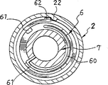
锁定切换环6呈环状,其内环面设有若干个斜推孔61,其外环面凸设与扭力盖2底端拨钮22相对应的突块62。The
拉簧60约为270°弧长。The
制动杆9呈短杆状,其上端91及下端93皆呈与半圆球状,并于上、下端91、93之间形成突环92,于突环92下方套设有弹簧90。The brake lever 9 is in the shape of a short rod, and its
止逆转结构包括转动盖84、转动接头85、固定座86、垫片87、滚柱88、轴承89及扣件80等。The anti-reverse structure includes a
顶柱70系由锁定切换环6压制,藉由扭力盖2的内螺纹22驱动螺丝环3,驱动螺丝环3上、下移动,以改变弹簧4经弹簧垫片40作用于锁定切换环6上的压制力,并经锁定切换环6将弹簧4的压制力施加于顶柱70上。当主轴所承受的轴向扭力大于弹簧4的压制力时,内齿轮8顶端突齿82与顶柱70底端即会产生安全跳脱作用。The
制动杆9滑动装设于间座7的阶状孔71内,其上、下端91、93可分别与锁定切换环6上的斜推孔61及内齿轮8的外齿槽83嵌合。The brake lever 9 is slidably installed in the
约为270°弧长的拉簧60的一端扣住锁定切换环6,其另一端则扣于间座7上。One end of an
如图4所示,拉簧60呈松弛状态。如图5所示,当旋转扭力盖2,藉由其底端与锁定切换环6上突块62相对应的拨钮22,以将锁定切换环6扣止定位。As shown in FIG. 4 , the
如图6、图7所示,锁定切换环6旋动移位,藉由其上斜推孔61将制动杆9下推,使其扣住内齿轮8外周的外齿槽83。As shown in FIG. 6 and FIG. 7 , the
如图4、图6所示,当锁定切换环6保持在常态位置时,其上斜推孔61对正制动杆9上端91,制动杆9在套设在其上弹簧90的弹力作用下,以其上端伸入锁定切换环6的斜推孔61内,而下端93仍保持在间座7的阶状孔71内,内齿轮8未被锁定而呈可调整状态。As shown in Fig. 4 and Fig. 6, when the
如图5、图7所示,当锁定切换环6旋动时,其上斜推孔61将制动杆9上端91下压,并压缩弹簧90,使制动杆9下端93嵌插入内齿轮8的外齿槽83内,内齿轮8呈被锁定状态,其动力完全输出而不受反扭力的影响。As shown in Fig. 5 and Fig. 7, when the
本实用新型主要提供一种利用反向旋动扭力盖2,以能拨动锁定切换环6,使锁定切换环6所设的若干斜推孔61抵压制动杆9下行,以嵌插入内齿轮8的外齿槽83内,使内齿轮8无法转动,即处于无扭力可调整的空间的状态,进而使主轴的动力可以完全输出,并使其锁定点的设置位置不会受到限制。The utility model mainly provides a method of rotating the
综上所述,本实用新型不仅为可旋转并多点卡定的扭力调整头,以藉由扭力调整头的旋转调整输出扭力,而且可仅作局部反向旋动即可锁定内齿轮,以锁定扭力调整空间,实现扭力完全输出,故可设置在常用的扭力级距旁侧,使锁定级邻近常用的扭力级距,便于切换使用,并因而能减少因切换导致机件损坏的问题。To sum up, the utility model is not only a rotatable and multi-point locking torque adjustment head, so as to adjust the output torque through the rotation of the torque adjustment head, but also can lock the internal gear only by partial reverse rotation, so as to The locking torque adjustment space realizes the full output of the torque, so it can be set beside the commonly used torque step, so that the locking step is close to the commonly used torque step, which is easy to switch and use, and thus can reduce the problem of machine damage caused by switching.
Claims (2)
Priority Applications (1)
| Application Number | Priority Date | Filing Date | Title |
|---|---|---|---|
| CN 00208964 CN2420103Y (en) | 2000-04-07 | 2000-04-07 | Adjustable head for electric hand tools that can be locked at will |
Applications Claiming Priority (1)
| Application Number | Priority Date | Filing Date | Title |
|---|---|---|---|
| CN 00208964 CN2420103Y (en) | 2000-04-07 | 2000-04-07 | Adjustable head for electric hand tools that can be locked at will |
Publications (1)
| Publication Number | Publication Date |
|---|---|
| CN2420103Y true CN2420103Y (en) | 2001-02-21 |
Family
ID=33576199
Family Applications (1)
| Application Number | Title | Priority Date | Filing Date |
|---|---|---|---|
| CN 00208964 Expired - Fee Related CN2420103Y (en) | 2000-04-07 | 2000-04-07 | Adjustable head for electric hand tools that can be locked at will |
Country Status (1)
| Country | Link |
|---|---|
| CN (1) | CN2420103Y (en) |
Cited By (3)
| Publication number | Priority date | Publication date | Assignee | Title |
|---|---|---|---|---|
| US8057134B2 (en) | 2007-06-26 | 2011-11-15 | Techtronic Power Tools Technology Limited | Chuck assembly |
| US8075229B2 (en) | 2007-06-26 | 2011-12-13 | Techtronic Power Tools Technology Limited | Multi-speed drill and chuck assembly |
| CN101841988B (en) * | 2009-03-21 | 2013-12-04 | 富准精密工业(深圳)有限公司 | Fastener |
-
2000
- 2000-04-07 CN CN 00208964 patent/CN2420103Y/en not_active Expired - Fee Related
Cited By (3)
| Publication number | Priority date | Publication date | Assignee | Title |
|---|---|---|---|---|
| US8057134B2 (en) | 2007-06-26 | 2011-11-15 | Techtronic Power Tools Technology Limited | Chuck assembly |
| US8075229B2 (en) | 2007-06-26 | 2011-12-13 | Techtronic Power Tools Technology Limited | Multi-speed drill and chuck assembly |
| CN101841988B (en) * | 2009-03-21 | 2013-12-04 | 富准精密工业(深圳)有限公司 | Fastener |
Similar Documents
| Publication | Publication Date | Title |
|---|---|---|
| JP5726755B2 (en) | Wrench giving maximum torque that is fixed or adjustable | |
| US7661341B2 (en) | Wrench with electronic torque display unit | |
| WO2007024006A3 (en) | Rotation/linear motion converting mechanism | |
| DE29923003U1 (en) | Structure of a ratchet wrench | |
| CN207014254U (en) | Torque socket with lock and release function | |
| DE3209395A1 (en) | SWITCH-OFF SCREWDRIVER WITH A SLIDING SCREWDRIVER | |
| CN2420103Y (en) | Adjustable head for electric hand tools that can be locked at will | |
| CN101879711A (en) | Torque adjustment and locking mechanism of torque tools | |
| JP5261630B2 (en) | Rotating tool | |
| US5371919A (en) | Coupling element for adjustable hand lever mechanism | |
| TWI504530B (en) | Cable adjustment device | |
| US20080276748A1 (en) | Gear Shifter | |
| US20070107560A1 (en) | Ratchet wrench | |
| JP2008543595A (en) | Ratchet wrench device | |
| CN2239329Y (en) | fine tuning torque wrench | |
| CN2712552Y (en) | Torque adjustable spanner | |
| CN218000994U (en) | Photographic Equipment Connection Module and Photographic Components | |
| CN206717734U (en) | Quick release device for bidirectional ratchet | |
| US20020124678A1 (en) | Shifting device for a bicycle | |
| EP0294720A2 (en) | Turning handle for brake and gear-change | |
| CN2423066Y (en) | Knob mechanism that produces sound and positioning effects when turned | |
| JP3226594U (en) | Positioning structure of frame clamp for string machine | |
| CN2434099Y (en) | ratchet wrench | |
| JP6830144B2 (en) | Fishing reel that makes it easy to adjust the distance of the tension nut | |
| CN2332744Y (en) | Sewing machine thread tension adjustment device |
Legal Events
| Date | Code | Title | Description |
|---|---|---|---|
| C14 | Grant of patent or utility model | ||
| GR01 | Patent grant | ||
| C19 | Lapse of patent right due to non-payment of the annual fee | ||
| CF01 | Termination of patent right due to non-payment of annual fee |